US6954221B2 - Safety structure of a desk top LCD - Google Patents
Safety structure of a desk top LCD Download PDFInfo
- Publication number
- US6954221B2 US6954221B2 US10/247,716 US24771602A US6954221B2 US 6954221 B2 US6954221 B2 US 6954221B2 US 24771602 A US24771602 A US 24771602A US 6954221 B2 US6954221 B2 US 6954221B2
- Authority
- US
- United States
- Prior art keywords
- section
- limiting
- monitor
- plate
- elevation angle
- Prior art date
- Legal status (The legal status is an assumption and is not a legal conclusion. Google has not performed a legal analysis and makes no representation as to the accuracy of the status listed.)
- Expired - Fee Related, expires
Links
Images


Classifications
-
- G—PHYSICS
- G06—COMPUTING; CALCULATING OR COUNTING
- G06F—ELECTRIC DIGITAL DATA PROCESSING
- G06F1/00—Details not covered by groups G06F3/00 - G06F13/00 and G06F21/00
- G06F1/16—Constructional details or arrangements
- G06F1/1601—Constructional details related to the housing of computer displays, e.g. of CRT monitors, of flat displays
-
- G—PHYSICS
- G06—COMPUTING; CALCULATING OR COUNTING
- G06F—ELECTRIC DIGITAL DATA PROCESSING
- G06F2200/00—Indexing scheme relating to G06F1/04 - G06F1/32
- G06F2200/16—Indexing scheme relating to G06F1/16 - G06F1/18
- G06F2200/161—Indexing scheme relating to constructional details of the monitor
- G06F2200/1612—Flat panel monitor
-
- Y—GENERAL TAGGING OF NEW TECHNOLOGICAL DEVELOPMENTS; GENERAL TAGGING OF CROSS-SECTIONAL TECHNOLOGIES SPANNING OVER SEVERAL SECTIONS OF THE IPC; TECHNICAL SUBJECTS COVERED BY FORMER USPC CROSS-REFERENCE ART COLLECTIONS [XRACs] AND DIGESTS
- Y10—TECHNICAL SUBJECTS COVERED BY FORMER USPC
- Y10S—TECHNICAL SUBJECTS COVERED BY FORMER USPC CROSS-REFERENCE ART COLLECTIONS [XRACs] AND DIGESTS
- Y10S248/00—Supports
- Y10S248/917—Video display screen support
- Y10S248/919—Adjustably orientable video screen support
- Y10S248/92—Angular and linear video display screen support adjustment
-
- Y—GENERAL TAGGING OF NEW TECHNOLOGICAL DEVELOPMENTS; GENERAL TAGGING OF CROSS-SECTIONAL TECHNOLOGIES SPANNING OVER SEVERAL SECTIONS OF THE IPC; TECHNICAL SUBJECTS COVERED BY FORMER USPC CROSS-REFERENCE ART COLLECTIONS [XRACs] AND DIGESTS
- Y10—TECHNICAL SUBJECTS COVERED BY FORMER USPC
- Y10S—TECHNICAL SUBJECTS COVERED BY FORMER USPC CROSS-REFERENCE ART COLLECTIONS [XRACs] AND DIGESTS
- Y10S248/00—Supports
- Y10S248/917—Video display screen support
- Y10S248/919—Adjustably orientable video screen support
- Y10S248/921—Plural angular
-
- Y—GENERAL TAGGING OF NEW TECHNOLOGICAL DEVELOPMENTS; GENERAL TAGGING OF CROSS-SECTIONAL TECHNOLOGIES SPANNING OVER SEVERAL SECTIONS OF THE IPC; TECHNICAL SUBJECTS COVERED BY FORMER USPC CROSS-REFERENCE ART COLLECTIONS [XRACs] AND DIGESTS
- Y10—TECHNICAL SUBJECTS COVERED BY FORMER USPC
- Y10S—TECHNICAL SUBJECTS COVERED BY FORMER USPC CROSS-REFERENCE ART COLLECTIONS [XRACs] AND DIGESTS
- Y10S248/00—Supports
- Y10S248/917—Video display screen support
- Y10S248/919—Adjustably orientable video screen support
- Y10S248/922—Angular
- Y10S248/923—Tilting
-
- Y—GENERAL TAGGING OF NEW TECHNOLOGICAL DEVELOPMENTS; GENERAL TAGGING OF CROSS-SECTIONAL TECHNOLOGIES SPANNING OVER SEVERAL SECTIONS OF THE IPC; TECHNICAL SUBJECTS COVERED BY FORMER USPC CROSS-REFERENCE ART COLLECTIONS [XRACs] AND DIGESTS
- Y10—TECHNICAL SUBJECTS COVERED BY FORMER USPC
- Y10S—TECHNICAL SUBJECTS COVERED BY FORMER USPC CROSS-REFERENCE ART COLLECTIONS [XRACs] AND DIGESTS
- Y10S345/00—Computer graphics processing and selective visual display systems
- Y10S345/904—Display with fail/safe testing feature
-
- Y—GENERAL TAGGING OF NEW TECHNOLOGICAL DEVELOPMENTS; GENERAL TAGGING OF CROSS-SECTIONAL TECHNOLOGIES SPANNING OVER SEVERAL SECTIONS OF THE IPC; TECHNICAL SUBJECTS COVERED BY FORMER USPC CROSS-REFERENCE ART COLLECTIONS [XRACs] AND DIGESTS
- Y10—TECHNICAL SUBJECTS COVERED BY FORMER USPC
- Y10S—TECHNICAL SUBJECTS COVERED BY FORMER USPC CROSS-REFERENCE ART COLLECTIONS [XRACs] AND DIGESTS
- Y10S345/00—Computer graphics processing and selective visual display systems
- Y10S345/905—Display device with housing structure
Definitions
- the present invention relates to a safety structure, and in particular a safety structure of a desk top LCD such that the desk top LCD is prevented from toppling when the monitor is turned to an inclination angle.
- FIG. 1 there is shown a convention desk top LCD having a chain 12 to mount a monitor 11 onto a base seat 10 such that the monitor can be adjusted with respect to an inclination or an elevation angle.
- the conventional inclination/elevation angle is normally 5 to 20 degree, and the drawbacks of such convention structure are as follows:
- the monitor can be easily toppled.
- the conventional monitor has a small adjustable angle and if a large force is applied to adjust the inclination/elevation angle, the monitor may be toppled.
- a safety structure of a desk-top Liquid Crystal Display having a seat body pivotally mounted to a monitor, characterized in that the monitor is provided with two sections of elevation angle, wherein the first section of the elevation angle complies with the angle of application for human body, and the second section of the elevation angle has a maximum elevation angle in parallel to a base seat of the monitor, and the twisting force of the monitor required to rotate within the scope of elevation angle of the second section is larger than that of the elevation angle of the first section, but the twisting force to rotate within the second section is smaller than the weight of the seat body.
- LCD Liquid Crystal Display
- An aspect of the present invention is to provide a safety structure of a desk-top Liquid Crystal Display (LCD) having a seat body pivotally mounted to a monitor and the pivoting device being a securing frame having two sides mounted corresponding with a chain, wherein the securing frame is fixed to the monitor and the two lateral sides of the securing frame are each provided with a protruded lug having provided with pivotal hole, and one side of the pivotal hole is provided with a limiting hole and the peripheral edge of the protruded lug is provided with a positioning notch;
- the chain includes a rotating shaft, a first section limiting plate, a second section limiting plate, a securing plate, a plurality of elastic pads, a plurality of damping plates, a top pressing pad, and a securing nuts, wherein the rotating shaft includes a combining section for mounting onto the seat body, and the upper section of a pivotal shaft is an engaging flat section and in turn passes through the first section limiting plate, a
- a further object of the present invention is to provide a safety structure of a desk-top Liquid Crystal Display (LCD), wherein the first section elevation angle is 5 degree of inclination to 20 degree of elevation angle, and the twisting force for rotation is about 11 to 16 kg/cm, and the second section elevation angle is inclination angle of 20 degree and the elevation angle of 90 degree, and the twisting force for rotation is about 45 to 55 kg/cm.
- LCD Liquid Crystal Display
- FIG. 1 is a conventional desk top LCD.
- FIG. 2 is a perspective exploded view in accordance with the present invention.
- FIG. 3 is a perspective exploded view of a chain in accordance with the present invention.
- FIG. 4 is a sectional view of the present invention.
- FIG. 5 is a lateral view of the present invention.
- FIG. 6 is a schematic view showing the forward inclined at the first section inclination/elevation angle in accordance with the present invention.
- FIG. 7 is a schematic view showing the backward inclined at the first section inclination/elevation angle in accordance with the present invention.
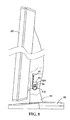
- FIG. 8 is a schematic view showing the action of the monitor within the range of second section inclination/elevation angle in accordance with the present invention.
- FIG. 9 is shows the present invention together with foamed material in accordance with the present invention.
- FIG. 10 is another preferred embodiment in accordance with the present invention.
- FIGS. 2 to 4 there is shown a safety structure of a desk-top Liquid Crystal Display (LCD) having a pivoting device A for pivotal mounting of a monitor 20 onto a side arm 31 of a seat body 30 , and as shown in FIG. 3 , the two lateral sides of a securing frame 40 are respectively mounted with a chain 50 , wherein the securing frame 40 includes a securing plate 41 for the securing of the monitor 11 , and a support plate 2 having the two lateral sides, each being provided with a protruded lug 43 having provided with pivotal hole 44 thereon for the pivotal mounting of the chain 40 , and one side of the pivotal hole 44 is provided with an arch-shaped limiting hole 45 .
- the peripheral edge of the protruded lug 43 is provided at an appropriate position with an arch-shaped positioning notch 46 , and the arch length of the positioning notch 46 is larger than the limiting hole 45 .
- the chain 50 includes a rotating shaft 51 , a first section limiting plate 52 , a second section limiting plate 53 , a securing plate 54 , a plurality of elastic pads 55 , a plurality of damping plates 56 , a top pressing pad 57 , and a securing nut 58 , wherein the rotating shaft 51 includes a combining section 510 , a pivotal shaft 511 and a threaded shaft rod 513 , wherein the combining section 510 for mounting onto the support arm 31 with screw 514 , and the pivotal shaft 511 has an engaging flat section 512 and in turn passes through the first section limiting plate 53 , a damping pad 56 , a second section limiting plate 53 , a damping pad 56 , a pivotal hole 44 on the protruded lug 43 , a damping pad 56 and a securing plate 54 , and a threaded shaft 513 is provided at one lateral side of the pivotal shaft 511 , and in sequence,
- the first section limiting plate 52 is provided with a circular through hole 520 for the mounting onto the pivotal shaft 511 , and one lateral side of the plate has a first limiting arm 521 , and the first limiting arm 521 is extended through the limiting hole 45 of the protruded lug 43 .
- the second section limiting plate 53 is provided with a mounting hole 530 and the shape of the mounting hole 530 is the same shape of the cross section of the pivotal shaft 511 so as to allow the rotation of the pivotal shaft 511 and one lateral side of the plate has a second limiting arm 531 and the second limiting arm 531 is extended to the positioning notch 46 at the circumferential edge of the protruded lug 43 .
- the securing plate 54 is provided with a circular hole 540 for the mounting onto the pivotal shaft 511 and is rotatable thereon, and one lateral side is provided with an engaging slot 541 for the passing through of the limiting hole 45 of the first limiting arm 521 for mounting.
- the elastic pad 55 is mounted onto the threaded shaft rod section 513 of the pivotal shaft 511 .
- a plurality of damping pads 56 are respectively located between the first limiting plate 52 and the second limiting plate 53 , the second limiting plate 53 and the protruded lug 43 , the protruded lug 43 and the securing plate 54 .
- the top pressing pad 57 is located at the external side of the elastic plate 55 , and the securing nut 58 is screwed to the threaded shaft rod 513 so as to allow the rotating shaft 51 , the first section limiting plate 52 , the second section limiting plate 53 , the securing plate 54 , a plurality of elastic pads 55 , a plurality of damping pads 56 and the top pressing pad 57 to be screwed on to the protruded lug 43 .
- the monitor 20 when the monitor 20 is pressed forward, the monitor 20 will rotate to an elevation of 5 degree at maximum as a result of the protruded lug 43 .
- the monitor 20 When one lateral top of the limiting hole 45 urges to the first limiting arm 521 , the monitor 20 will not move further (as shown in FIG. 6 ).
- the monitor 11 When the monitor 20 is pressed at the rear side, the monitor 11 will move at an appropriate inclination angle as a result of the protruded lug 43 at a maximum of 20 degree. That is when other lateral top of the limiting hole urges the first limiting arm 521 , the angle of rotating is 5 to 20 as this is the first section of the angle (as shown in FIG. 7 ).
- the required twisting force to provide rotating is that the force is slightly larger than the total frictional force of the second limiting plate 53 and the protruded lug 43 and the protruded lug 43 and the securing plate 54 with the damping pad 56 , that is the force is about 11 to 16 kg/cm.
- the protruded lug 43 when the monitor 20 is pressed at the rear end to the maximum angle of inclination, and then a force is further applied, the protruded lug 43 will drive the first limiting plate 52 to rotate.
- the protruded lug 45 is rotated to an appropriate angle, one lateral wall of the positioning notch 46 will urge the second limiting arm 531 and the limiting plate 53 will not rotate as the pivotal shaft 511 is secured to the side arm 3 of the seat body 30 .
- the monitor 20 will rotate and position at 90 degree, and the angle between 20 to 90 is the second section of elevation angle (as shown in FIG. 8 ).
- the twisting force required for rotating at the second section of the elevation angle is slightly larger than the total friction force between the first limiting plate 52 and the second limiting plate 53 , the second limiting plate 53 and the protruded lug 43 , and the protruded lug 43 and the securing plate 54 with the damping pads 56 , and the total is about 45 to 55 kg/cm, and the twisting force is smaller than the weight of the seat body 30 so as to cause the rotating at second section rotating but the set body will not rotate.
- the foamed material 60 is placed into the engaging slot 61 for the positioning of the monitor 20 and the seat body 30 .
- the pivotal device A can be two separate securing frames 40 having a chain mounted thereto.
- the monitor will not be toppled as a result of external force. As the monitor 20 can be pushed backward to a larger angle of elevation, and the center of gravity is thus lowered, the toppling of the monitor is avoided.
- the monitor 20 can be rotated so as to be located in parallel to the seat body 30 , the capacity of the package is reduced.
- the depth of the packing box 62 and the foamed material is greatly reduced and the foamed material needed is lesser.
Abstract
Description
Claims (7)
Priority Applications (1)
| Application Number | Priority Date | Filing Date | Title |
|---|---|---|---|
| US10/247,716 US6954221B2 (en) | 2002-09-20 | 2002-09-20 | Safety structure of a desk top LCD |
Applications Claiming Priority (1)
| Application Number | Priority Date | Filing Date | Title |
|---|---|---|---|
| US10/247,716 US6954221B2 (en) | 2002-09-20 | 2002-09-20 | Safety structure of a desk top LCD |
Publications (2)
| Publication Number | Publication Date |
|---|---|
| US20040056836A1 US20040056836A1 (en) | 2004-03-25 |
| US6954221B2 true US6954221B2 (en) | 2005-10-11 |
Family
ID=31992548
Family Applications (1)
| Application Number | Title | Priority Date | Filing Date |
|---|---|---|---|
| US10/247,716 Expired - Fee Related US6954221B2 (en) | 2002-09-20 | 2002-09-20 | Safety structure of a desk top LCD |
Country Status (1)
| Country | Link |
|---|---|
| US (1) | US6954221B2 (en) |
Cited By (30)
| Publication number | Priority date | Publication date | Assignee | Title |
|---|---|---|---|---|
| US20040035994A1 (en) * | 2002-08-24 | 2004-02-26 | Samsung Electronics Co., Ltd | Display apparatus |
| US20050017135A1 (en) * | 2001-11-19 | 2005-01-27 | Samsung Electronics Co., Ltd. | Monitor improved in a tilting and combining structure |
| US20050105257A1 (en) * | 2003-01-14 | 2005-05-19 | Yosuke Shimizu | Display apparatus |
| US20050207101A1 (en) * | 2004-03-17 | 2005-09-22 | Chi Lin Technology Co., Ltd. | Display device having an adjustable display screen |
| US20060113434A1 (en) * | 2004-11-29 | 2006-06-01 | Harald Richter | Apparatus support console with adjustable support plate |
| US20060231697A1 (en) * | 2005-04-19 | 2006-10-19 | Amtran Technology Co., Ltd. | Display device with a bracket covering |
| US20060237599A1 (en) * | 2005-04-22 | 2006-10-26 | John Ternus | Flat panel display including a hinge assembly |
| US20060278796A1 (en) * | 2005-03-31 | 2006-12-14 | Lu Sheng-Nan | Hinge |
| US20060282982A1 (en) * | 2005-06-10 | 2006-12-21 | Samsung Electronics Co., Ltd. | Door damper and electronic appliances having the same |
| US20070097608A1 (en) * | 2005-04-20 | 2007-05-03 | Funai Electric Co., Ltd. | LCD apparatus |
| US20070121280A1 (en) * | 2005-11-25 | 2007-05-31 | Inventec Corporation | Display used on a desk or a wall |
| US20070119025A1 (en) * | 2005-11-25 | 2007-05-31 | Hon Hai Precision Industry Co., Ltd. | Hinge assembly for flat display monitor |
| US20070136995A1 (en) * | 2005-12-01 | 2007-06-21 | Hon Hai Precision Industry Co., Ltd. | Hinge assembly for flat display monitor |
| US20070136994A1 (en) * | 2005-12-01 | 2007-06-21 | Hon Hai Precision Industry Co., Ltd. | Hinge assembly for flat display monitor |
| US20070152114A1 (en) * | 2005-12-30 | 2007-07-05 | Lg Electronics Inc. | Stand for display device |
| US20070283533A1 (en) * | 2006-06-09 | 2007-12-13 | Shin Zu Shing Co., Ltd. | Hinge assembly |
| US20080007906A1 (en) * | 2006-07-07 | 2008-01-10 | Hon Hai Precision Industry Co., Ltd. | Hinge assembly with stop and display monitor having same |
| US20080034551A1 (en) * | 2006-05-25 | 2008-02-14 | Lg Electronics Inc. | Hinge assembly for electronic appliance and stand apparatus having the same |
| US20080040887A1 (en) * | 2006-08-16 | 2008-02-21 | Dickerson Harry L | Friction hinge for electronic apparatus |
| US20080099652A1 (en) * | 2006-10-27 | 2008-05-01 | Funai Electric Co., Ltd. | Display screen turning apparatus |
| US20080109992A1 (en) * | 2006-11-13 | 2008-05-15 | Shin Zu Shing Co., Ltd. | Hinge with less abrasion |
| US20080141493A1 (en) * | 2006-12-19 | 2008-06-19 | Hong Fu Jin Precision Industry (Shenzhen) Co., Ltd | Hinge assembly and display monitor with the same |
| US20080148521A1 (en) * | 2006-10-30 | 2008-06-26 | Sony Ericsson Mobile Communications Ab | Hinge with Anti-Skew Features |
| US20080163460A1 (en) * | 2007-01-04 | 2008-07-10 | Brett William Degner | Hinge mechanism |
| US7430786B1 (en) * | 2007-04-23 | 2008-10-07 | Shin Zu Shing Co., Ltd. | Triple positioning hinge |
| US20080265121A1 (en) * | 2007-04-27 | 2008-10-30 | Drew Paul L | Display stand |
| US20100096515A1 (en) * | 2007-10-12 | 2010-04-22 | Joel Hazzard | Convertible Display Stand System and Method |
| US20100172073A1 (en) * | 2009-01-06 | 2010-07-08 | Innocom Technology (Shenzhen) Co., Ltd. | Flat panel display with support providing pivoting |
| US20100208419A1 (en) * | 2009-02-19 | 2010-08-19 | Samsung Mobile Display Co., Ltd, | Apparatus for controlling inclination of organic light emitting display panel |
| US20120229427A1 (en) * | 2011-03-07 | 2012-09-13 | Fih (Hong Kong) Limited | Stylus |
Citations (3)
| Publication number | Priority date | Publication date | Assignee | Title |
|---|---|---|---|---|
| US5398991A (en) * | 1993-02-09 | 1995-03-21 | Sony Trans Com Incorporated | Seat arm display monitor deployment mechanism |
| US20010048584A1 (en) * | 2000-01-06 | 2001-12-06 | Rosen Products Llc. | Adjustable display monitor unit |
| US6532628B2 (en) * | 2000-07-08 | 2003-03-18 | Lg Electronics Inc. | Hinge assembly for LCD monitor |
-
2002
- 2002-09-20 US US10/247,716 patent/US6954221B2/en not_active Expired - Fee Related
Patent Citations (3)
| Publication number | Priority date | Publication date | Assignee | Title |
|---|---|---|---|---|
| US5398991A (en) * | 1993-02-09 | 1995-03-21 | Sony Trans Com Incorporated | Seat arm display monitor deployment mechanism |
| US20010048584A1 (en) * | 2000-01-06 | 2001-12-06 | Rosen Products Llc. | Adjustable display monitor unit |
| US6532628B2 (en) * | 2000-07-08 | 2003-03-18 | Lg Electronics Inc. | Hinge assembly for LCD monitor |
Cited By (54)
| Publication number | Priority date | Publication date | Assignee | Title |
|---|---|---|---|---|
| US20050017135A1 (en) * | 2001-11-19 | 2005-01-27 | Samsung Electronics Co., Ltd. | Monitor improved in a tilting and combining structure |
| US7819368B2 (en) * | 2001-11-19 | 2010-10-26 | Samsung Electronics Co., Ltd. | Monitor improved in a tilting and combining structure |
| US20040035994A1 (en) * | 2002-08-24 | 2004-02-26 | Samsung Electronics Co., Ltd | Display apparatus |
| US7245481B2 (en) * | 2003-01-14 | 2007-07-17 | Sony Corporation | Display apparatus |
| US20050105257A1 (en) * | 2003-01-14 | 2005-05-19 | Yosuke Shimizu | Display apparatus |
| US20050207101A1 (en) * | 2004-03-17 | 2005-09-22 | Chi Lin Technology Co., Ltd. | Display device having an adjustable display screen |
| US20060113434A1 (en) * | 2004-11-29 | 2006-06-01 | Harald Richter | Apparatus support console with adjustable support plate |
| US7731135B2 (en) * | 2004-11-29 | 2010-06-08 | Harald Richter | Apparatus support console with adjustable support plate |
| US20060278796A1 (en) * | 2005-03-31 | 2006-12-14 | Lu Sheng-Nan | Hinge |
| US7193843B2 (en) * | 2005-04-19 | 2007-03-20 | Amtran Technology Co., Ltd. | Display device with a bracket covering |
| US20060231697A1 (en) * | 2005-04-19 | 2006-10-19 | Amtran Technology Co., Ltd. | Display device with a bracket covering |
| US20070097608A1 (en) * | 2005-04-20 | 2007-05-03 | Funai Electric Co., Ltd. | LCD apparatus |
| US7651062B2 (en) * | 2005-04-20 | 2010-01-26 | Funai Electric Co., Ltd. | LCD apparatus |
| US8387928B2 (en) | 2005-04-22 | 2013-03-05 | Apple Inc. | Flat panel display including a hinge assembly |
| US8820687B2 (en) | 2005-04-22 | 2014-09-02 | Apple Inc. | Flat panel display including a hinge assembly |
| US20090230270A1 (en) * | 2005-04-22 | 2009-09-17 | Apple Inc. | Flat panel display including a hinge assembly |
| US8118269B2 (en) * | 2005-04-22 | 2012-02-21 | Apple Inc. | Flat panel display including a hinge assembly |
| US20060237599A1 (en) * | 2005-04-22 | 2006-10-26 | John Ternus | Flat panel display including a hinge assembly |
| US7357231B2 (en) * | 2005-06-10 | 2008-04-15 | Samsung Electronics Co., Ltd. | Door damper and electronic appliances having the same |
| US20060282982A1 (en) * | 2005-06-10 | 2006-12-21 | Samsung Electronics Co., Ltd. | Door damper and electronic appliances having the same |
| US7286342B2 (en) * | 2005-11-25 | 2007-10-23 | Inventec Corporation | Display used on a desk or a wall |
| US20070119025A1 (en) * | 2005-11-25 | 2007-05-31 | Hon Hai Precision Industry Co., Ltd. | Hinge assembly for flat display monitor |
| US20070121280A1 (en) * | 2005-11-25 | 2007-05-31 | Inventec Corporation | Display used on a desk or a wall |
| US20070136994A1 (en) * | 2005-12-01 | 2007-06-21 | Hon Hai Precision Industry Co., Ltd. | Hinge assembly for flat display monitor |
| US20070136995A1 (en) * | 2005-12-01 | 2007-06-21 | Hon Hai Precision Industry Co., Ltd. | Hinge assembly for flat display monitor |
| US7748680B2 (en) * | 2005-12-30 | 2010-07-06 | Lg Electronics Inc. | Foldable stand for display device |
| US20070152114A1 (en) * | 2005-12-30 | 2007-07-05 | Lg Electronics Inc. | Stand for display device |
| US7707691B2 (en) * | 2006-05-25 | 2010-05-04 | Lg Electronics Inc. | Hinge assembly for electronic appliance and stand apparatus having the same |
| US20080034551A1 (en) * | 2006-05-25 | 2008-02-14 | Lg Electronics Inc. | Hinge assembly for electronic appliance and stand apparatus having the same |
| US20070283533A1 (en) * | 2006-06-09 | 2007-12-13 | Shin Zu Shing Co., Ltd. | Hinge assembly |
| US7520024B2 (en) * | 2006-06-09 | 2009-04-21 | Shin Zu Shing Co., Ltd. | Hinge assembly |
| US20080007906A1 (en) * | 2006-07-07 | 2008-01-10 | Hon Hai Precision Industry Co., Ltd. | Hinge assembly with stop and display monitor having same |
| US20080040887A1 (en) * | 2006-08-16 | 2008-02-21 | Dickerson Harry L | Friction hinge for electronic apparatus |
| US20080099652A1 (en) * | 2006-10-27 | 2008-05-01 | Funai Electric Co., Ltd. | Display screen turning apparatus |
| US8094244B2 (en) * | 2006-10-27 | 2012-01-10 | Funai Electric Co., Ltd. | Display screen turning apparatus |
| US7665186B2 (en) * | 2006-10-30 | 2010-02-23 | Sony Ericsson Mobile Communications Ab | Hinge with anti-skew features |
| US20080148521A1 (en) * | 2006-10-30 | 2008-06-26 | Sony Ericsson Mobile Communications Ab | Hinge with Anti-Skew Features |
| US20080109992A1 (en) * | 2006-11-13 | 2008-05-15 | Shin Zu Shing Co., Ltd. | Hinge with less abrasion |
| US7555817B2 (en) * | 2006-11-13 | 2009-07-07 | Shin Zu Shing Co., Ltd. | Hinge with less abrasion |
| US20080141493A1 (en) * | 2006-12-19 | 2008-06-19 | Hong Fu Jin Precision Industry (Shenzhen) Co., Ltd | Hinge assembly and display monitor with the same |
| US7712187B2 (en) * | 2006-12-19 | 2010-05-11 | Hong Fu Jin Precision Industry (Shenzhen) Co., Ltd. | Hinge assembly and display monitor with the same |
| US8230553B2 (en) | 2007-01-04 | 2012-07-31 | Apple Inc. | Hinge mechanism |
| US20080163460A1 (en) * | 2007-01-04 | 2008-07-10 | Brett William Degner | Hinge mechanism |
| US7934292B2 (en) * | 2007-01-04 | 2011-05-03 | Apple Inc. | Hinge mechanism |
| US7430786B1 (en) * | 2007-04-23 | 2008-10-07 | Shin Zu Shing Co., Ltd. | Triple positioning hinge |
| US20080256749A1 (en) * | 2007-04-23 | 2008-10-23 | Shin Zu Shing Co., Ltd. | Triple positioning hinge |
| US20080265121A1 (en) * | 2007-04-27 | 2008-10-30 | Drew Paul L | Display stand |
| US8387930B2 (en) * | 2007-04-27 | 2013-03-05 | Hewlett-Packard Development Company, L.P. | Display stand |
| US20100096515A1 (en) * | 2007-10-12 | 2010-04-22 | Joel Hazzard | Convertible Display Stand System and Method |
| US8199472B2 (en) * | 2009-01-06 | 2012-06-12 | Innocom Technology (Shenzhen) Co., Ltd. | Flat panel display with support providing pivoting |
| US20100172073A1 (en) * | 2009-01-06 | 2010-07-08 | Innocom Technology (Shenzhen) Co., Ltd. | Flat panel display with support providing pivoting |
| US8345413B2 (en) * | 2009-02-19 | 2013-01-01 | Samsung Display Co., Ltd. | Apparatus for controlling inclination of organic light emitting display panel |
| US20100208419A1 (en) * | 2009-02-19 | 2010-08-19 | Samsung Mobile Display Co., Ltd, | Apparatus for controlling inclination of organic light emitting display panel |
| US20120229427A1 (en) * | 2011-03-07 | 2012-09-13 | Fih (Hong Kong) Limited | Stylus |
Also Published As
| Publication number | Publication date |
|---|---|
| US20040056836A1 (en) | 2004-03-25 |
Similar Documents
| Publication | Publication Date | Title |
|---|---|---|
| US6954221B2 (en) | Safety structure of a desk top LCD | |
| US6837469B2 (en) | Structure of liquid crystal display (LCD) | |
| US20030075653A1 (en) | Liquid crystal display support | |
| US7770856B2 (en) | Thin computer monitor support apparatus | |
| US6592090B1 (en) | Object supporting structure | |
| US6532628B2 (en) | Hinge assembly for LCD monitor | |
| US6367756B1 (en) | Adjustable device support and anchor means arrangement | |
| US8002223B2 (en) | Display support mechanism | |
| KR100627875B1 (en) | Supporter for vehicle | |
| US20080054133A1 (en) | Supporting arm for a monitor screen | |
| KR20050095755A (en) | Display apparatus | |
| US6962312B2 (en) | Display apparatus with adjustable supporting device | |
| US20070138369A1 (en) | Support apparatus | |
| JPH08289229A (en) | Storage rack for television receiver | |
| JP2009069554A (en) | Thin-type monitoring device | |
| KR200404248Y1 (en) | Supporter for vehicle | |
| JP2000179538A (en) | Pivot ratchet system for flat panel display or key-board | |
| US5938159A (en) | Computer monitor supporting bracket | |
| US20120224306A1 (en) | Display apparatus and support stand | |
| US20080158811A1 (en) | Universal attachment for computer peripheral equipment | |
| US20090268106A1 (en) | Display Screen Support Mechanism and Television Set | |
| JPH05266643A (en) | Stand for external memory | |
| US20010055075A1 (en) | Liquid crystal display and rotating device of the same | |
| KR20040068485A (en) | apparatus for an inclination motion | |
| CN217928130U (en) | Support and projection system |
Legal Events
| Date | Code | Title | Description |
|---|---|---|---|
| FEPP | Fee payment procedure |
Free format text: PAYOR NUMBER ASSIGNED (ORIGINAL EVENT CODE: ASPN); ENTITY STATUS OF PATENT OWNER: LARGE ENTITY Free format text: PAT HOLDER NO LONGER CLAIMS SMALL ENTITY STATUS, ENTITY STATUS SET TO UNDISCOUNTED (ORIGINAL EVENT CODE: STOL); ENTITY STATUS OF PATENT OWNER: LARGE ENTITY |
|
| FPAY | Fee payment |
Year of fee payment: 4 |
|
| FPAY | Fee payment |
Year of fee payment: 8 |
|
| REMI | Maintenance fee reminder mailed | ||
| LAPS | Lapse for failure to pay maintenance fees |
Free format text: PATENT EXPIRED FOR FAILURE TO PAY MAINTENANCE FEES (ORIGINAL EVENT CODE: EXP.) |
|
| STCH | Information on status: patent discontinuation |
Free format text: PATENT EXPIRED DUE TO NONPAYMENT OF MAINTENANCE FEES UNDER 37 CFR 1.362 |
|
| FP | Lapsed due to failure to pay maintenance fee |
Effective date: 20171011 |