US6967335B1 - Manipulation system for manipulating a sample under study with a microscope - Google Patents
Manipulation system for manipulating a sample under study with a microscope Download PDFInfo
- Publication number
- US6967335B1 US6967335B1 US10/173,542 US17354202A US6967335B1 US 6967335 B1 US6967335 B1 US 6967335B1 US 17354202 A US17354202 A US 17354202A US 6967335 B1 US6967335 B1 US 6967335B1
- Authority
- US
- United States
- Prior art keywords
- sample
- microscope
- sample holder
- interface
- manipulation
- Prior art date
- Legal status (The legal status is an assumption and is not a legal conclusion. Google has not performed a legal analysis and makes no representation as to the accuracy of the status listed.)
- Expired - Lifetime, expires
Links
Images


Classifications
-
- H—ELECTRICITY
- H01—ELECTRIC ELEMENTS
- H01J—ELECTRIC DISCHARGE TUBES OR DISCHARGE LAMPS
- H01J37/00—Discharge tubes with provision for introducing objects or material to be exposed to the discharge, e.g. for the purpose of examination or processing thereof
- H01J37/02—Details
- H01J37/20—Means for supporting or positioning the objects or the material; Means for adjusting diaphragms or lenses associated with the support
-
- G—PHYSICS
- G02—OPTICS
- G02B—OPTICAL ELEMENTS, SYSTEMS OR APPARATUS
- G02B21/00—Microscopes
- G02B21/32—Micromanipulators structurally combined with microscopes
Definitions
- the present invention relates in general to a manipulation system for manipulating a sample under study with a microscope, and more particularly to a manipulation system that comprises an interface for detachably coupling with at least one type of microscope, a sample stage for receiving a sample, and at least one manipulator mechanism for manipulating a received sample.
- micrometer ( ⁇ m) and nanometer (nm) size scales Much development is being achieved on the micrometer ( ⁇ m) and nanometer (nm) size scales. For example, much work is being performed at these small size scales in such scientific fields as biology, medicine, physics, chemistry, electronics, engineering, and nanotechnology to, for example, study objects (e.g., materials, organisms, viruses, bacteria, etc.), create new objects, and/or assemble objects together with great precision.
- study objects e.g., materials, organisms, viruses, bacteria, etc.
- magnification achievable with light microscopes is limited by the physics of light (i.e., the wavelength of light) upon which the operation of such microscopes is based.
- light microscopes have relatively limited resolving power (ability to distinguish clearly between two points very close together).
- the resolving power, ⁇ is measured by the angular separation of two point sources that are just detectably separated by the instrument.
- Modern electron microscopes typically comprise: (1) an electron gun to produce a beam of accelerated electrons; (2) an image producing system that includes electrostatic lenses (e.g., generally formed by electromagnetic or permanent magnets) and metal apertures to confine and focus the electron beam, pass it through, or over, the surface of the specimen and create a magnified image; (3) an image viewing and recording system, which typically includes photographic plates or a fluorescent screen; and (4) a vacuum pump to keep the microscope under high vacuum, as air molecules may deflect electrons from their paths.
- electrostatic lenses e.g., generally formed by electromagnetic or permanent magnets
- metal apertures to confine and focus the electron beam, pass it through, or over, the surface of the specimen and create a magnified image
- an image viewing and recording system which typically includes photographic plates or a fluorescent screen
- (4) a vacuum pump to keep the microscope under high vacuum, as air molecules may deflect electrons from their paths.
- TEM transmission electron microscope
- SEM scanning electron microscope
- the beam of electrons is focussed to a point and scanned over the surface of the specimen.
- Detectors collect the backscattered and secondary electrons coming from the surface and convert them into a signal that in turn is used to produce a realistic, three-dimensional image of the specimen.
- the detector receives back fewer electrons from depressions in the surface, and therefore lower areas of the surface appear darker in the resulting image.
- SEMs generally require the specimen to be electrically conducting.
- specimens that are not conducting are typically coated (e.g., using a sputter coater) with a thin layer of metal (often gold) prior to scanning.
- SEMs can magnify up to around one hundred thousand times or more and are used extensively, particularly in such scientific areas as biology, medicine, physics, chemistry, and engineering to, for example, study the three-dimensional (“3-D”) structure of surfaces from metals and ceramics to blood cells and insect bodies.
- 3-D three-dimensional
- microscopes have also been developed to aid in the study of micro- and/or nano-scale objects, including without limitation atomic force microscopes (AFMs), scanning probe microscopes (SPMs), have been developed, such as atomic force microscopes (AFMs), scanning tunnelling microscope (STM), and her field optical scanning microscope (NOSM), as examples.
- AFMs atomic force microscopes
- SPMs scanning probe microscopes
- NOSM her field optical scanning microscope
- Microscopes have traditionally been used for imaging (e.g., viewing specimens).
- a manipulator mechanism that may be used in conjunction with the microscope for manipulating a specimen being imaged by the microscope.
- manipulator mechanisms such as probes
- LEO ELECTRON MICROSCOPY LTD. has proposed certain manipulating mechanisms for use with an SEM.
- manipulator mechanisms, such as probes have been developed that are integrated within a TEM for manipulating a sample being imaged by the TEM.
- NANOFACTORY INSTRUMENTS has proposed certain in situ probes for TEMs.
- detachable manipulator mechanisms have been developed that are capable of being removably coupled to a TEM.
- NANOFACTORY INSTRUMENTS has proposed such a detachable manipulator mechanism for TEMs.
- the detachable manipulator mechanism comprises a sample stage for receiving a sample to be imaged by a TEM, and it further comprises one manipulator having an end-effector, such as a probe, for manipulating a sample.
- the detachable manipulator mechanism also comprises a first actuator mechanism that is operable to provide relatively long-range movement for coarse adjustment of the end-effector, and it further comprises a second actuator mechanism that is operable to provide relatively fine, precise positioning of the end-effector.
- a sample is arranged on the detachable manipulator mechanism's sample stage, and the detachable manipulator mechanism is then inserted into a TEM's sample chamber.
- the manipulator mechanism's first actuator mechanism is utilized to initially arrange the end-effector relative to the sample arranged on the sample stage.
- Such first actuator mechanism may comprise, for example, a long-stepper microactuator that provides relatively long-range movement with relatively coarse precision (e.g., depending on the step resolution of the long-stepper microactuator). Accordingly, the first actuator provides relatively coarse adjustment of the end-effector relative to the sample arranged on the sample stage.
- the second actuator mechanism may be used to perform relatively fine, precise movement of the end-effector to manipulate the sample arranged on the sample stage.
- detachable manipulator mechanisms of the existing art have comprised only one manipulator (end-effector) for manipulating a sample. Additionally, such detachable manipulator mechanisms of the existing art have been useable only with TEMs, and thus are not useable with other types of microscopes.
- manipulating mechanisms e.g., probes
- microscopes such as SEMs and TEMs
- manipulating mechanisms have traditionally been developed for use with a specific type of microscope.
- manipulating mechanisms that are developed for use in an SEM are not useable in TEMs, and vice-versa.
- manipulating mechanisms that are developed for one SEM e.g., a first model
- manipulating mechanisms that are developed for one SEM may not be useable in a different type of SEM (e.g., a different model).
- manipulating mechanisms of the existing art have lacked the flexibility of being interchangeably implemented with different types of microscope interfaces.
- manipulating mechanisms of the existing art have lacked a flexible interface that is readily adaptable for use with different types of microscopes.
- detachable manipulating mechanisms have been developed for TEMs, but such detachable manipulator mechanisms comprise only a single manipulator (or “end-effector”) for manipulating a sample.
- a manipulator mechanism would preferably be interfaced to a microscope, such as an SEM or TEM as examples, to provide manipulation capability, but would not interfere with a user desiring to utilize the standard functionality (e.g., imaging functionality) of the microscope.
- a detachable manipulator mechanism that is capable of being detachably coupled to a microscope, such as a TEM and/or SEM, and that comprises a plurality of manipulators that are controllably operable to manipulate a sample under study with such microscope.
- a manipulation system is adaptable for interfacing with any of a plurality of different types of microscopes.
- a manipulation system comprises an interface that is adjustable to comply with a plurality of different microscope interfaces.
- the manipulation system further comprises at least one manipulation mechanism operable to manipulate a sample.
- a portable sample holder for holding a sample for presentation to a microscope.
- the portable sample holder comprises a stage for receiving a sample, at least one manipulation mechanism for manipulating a received sample, and an interface for coupling with a microscope.
- the portable sample holder comprises a plurality of manipulation mechanisms for manipulating a received sample.
- the portable sample holder comprises at least four of such manipulation mechanisms. Having a plurality of manipulation mechanisms enables a variety of measurements to be acquired for a sample that have traditionally been unavailable.
- the interface of the portable sample holder is adaptable to conform to a plurality of different types of microscope interfaces.
- the interface is adaptable to conform at least to a transmission electron microscope (TEM) interface and a scanning electron microscope (SEM) interface.
- TEM transmission electron microscope
- SEM scanning electron microscope
- a method of using a microscope to study a sample comprises selecting a desired type of a plurality of different types of microscopes, each of the plurality of different types of microscopes having a different type of interface for receiving a sample holder.
- the method further comprises adjusting an interface of a sample holder to conform to the interface of the desired type of microscope, wherein said sample holder's interface is adjustable to conform to any of the different types of microscope interfaces for receiving a sample holder.
- the method further comprises arranging a sample on the sample holder, and interfacing the sample holder with the desired type of microscope such that the sample can be imaged by such desired type of microscope.
- the sample holder comprises at least one manipulation mechanism, and the method further comprises manipulating the sample using such manipulation mechanism(s).
- certain embodiments of the present invention provide a manipulation system with great flexibility in that it may be utilized with any of a plurality of different types of microscopes.
- Certain embodiments provide a manipulation system that is integrated within a sample holder, and the sample holder comprises an adjustable interface that enables such sample holder to be coupled to any of a plurality of different microscopes that have different interfaces for receiving such sample holder.
- the manipulation system of embodiments of the present invention is preferably capable of interfacing with a plurality of different types of microscopes in a manner that does not otherwise interfere with the normal operation (e.g., imaging functionality) of such microscope.
- the manipulation system may preferably be interfaced to a microscope, such as an SEM or TEM as examples, to provide the ability to manipulate a sample under study, but does not interfere with a user desiring to utilize the standard functionality (e.g., imaging functionality) of the microscope.
- a manipulation system that is capable of being detachably coupled to a microscope that comprises a plurality of manipulator mechanisms for manipulating a sample.
- a sample holder comprises a plurality of manipulator mechanisms that each includes an end-effector and an actuator mechanism for imparting movement to such end-effector.
- such actuator mechanism is operable for imparting relatively precise movement (e.g., with nanometer-scale or better precision) to the end-effector for manipulating a sample under study with a microscope.
- an adjustment mechanism that is independent from the sample holder may be used to perform relatively coarse adjustment of the sample holder's end-effector(s) in order to initially position such end-effector(s).
- the sample holder may be interface with a microscope (e.g., may be inserted in the sample chamber of a microscope), and the sample holder's actuators may be used to impart movement to its end-effectors in order to precisely position such end-effectors for manipulating a sample under study with the microscope.
- a microscope e.g., may be inserted in the sample chamber of a microscope
- the sample holder's actuators may be used to impart movement to its end-effectors in order to precisely position such end-effectors for manipulating a sample under study with the microscope.
- a system comprises a sample holder that includes a sample stage for receiving a sample, an interface for coupling the sample holder with a microscope such that a sample received on the sample stage can be imaged by the microscope, and a plurality of manipulator means for manipulating a received sample.
- each of such plurality of manipulator means comprises an end-effector, and multiple ones of such manipulator means each comprises an actuator means for imparting precise movement to its respective end-effector from an initial position to a desired position.
- the system may further comprise an adjustment means that is independent from the sample holder, wherein such adjustment means is operable for coarsely adjusting at least one of the sample holder's manipulator mechanisms to position such manipulator mechanism's end-effector to an initial position.
- a manipulation system that comprises an interface for detachably coupling with a microscope and further comprises a plurality of manipulator mechanisms for manipulating a sample.
- each of the plurality of manipulator mechanisms comprises an end-effeotor and an actuator for imparting.. movement to such end-effector.
- each of the actuators are independently operable in order to enable independent movement of the plurality of end-effectors included in the manipulation system.
- Such manipulation system may, in certain embodiments, be integrated within a sample holder that is comprises an interface for being detachably coupled to a microscope's sample chamber.
- FIG. 1 shows a typical configuration of a TEM
- FIG. 2 shows a typical configuration of an SEM
- FIGS. 3A-3B show an example configuration of a manipulation system in accordance with a preferred embodiment of the present invention
- FIGS. 4A-4B show a preferred embodiment of a manipulation system coupled to a light microscope to enable relatively coarse positioning of its manipulation mechanism(s) relative to a sample;
- FIG. 5 shows a manipulation system of a preferred embodiment of the present invention coupled with a TEM
- FIG. 6 shows a manipulation system of a preferred embodiment of the present invention coupled with an SEM
- FIG. 7 shows an example block diagram of a preferred embodiment of the present invention
- FIG. 8 shows an operational flow diagram that illustrates an example of how certain embodiments of the present invention may be utilized.
- FIG. 9 shows an operational flow diagram that illustrates an example of how certain embodiments of the present invention may be utilized.
- a manipulation system comprising an interface for a plurality of different types of microscopes.
- the manipulation system preferably comprises an adjustable interface that is adaptable for compliance with any of a plurality of different types of microscopes.
- the manipulation system comprises an interface that is adaptable for use at least with a plurality of different types of electron microscopes, such as SEMs and TEMs.
- the manipulation system comprises an interface that is adaptable for use with other types of microscopes in addition to or instead of electron microscopes.
- the manipulation system further comprises at least one manipulation mechanism for manipulating a sample (or “specimen”) being imaged by a microscope to which the manipulation system is coupled.
- manipulation mechanism may comprise any of various types of manipulation mechanisms, including without limitation probe(s) (including piezoelectric or cantilever force probes, or thermal probes, as examples), gripper(s), glass fiber(s), hypodermic needle(s), and hose(s) for manipulating a sample under study with the microscope.
- the manipulation system comprises a plurality of manipulation mechanisms for manipulating a sample under study.
- the manipulation mechanism(s) are controllably operable to perform nanometer-scale manipulation (which may be referred to herein as “nanomanipulation”).
- the manipulation mechanism(s) are preferably controllably moveable (e.g., via an actuation mechanism coupled hereto) with nanometer-scale precision.
- Manipulation is used herein in its broadest sense, and is not intended to be limited solely to actions that result in a change in the sample under study. Rather, certain types of manipulation may not alter the sample at all, but may instead aid in observing the sample (e.g., measuring certain characteristics of the sample). For example, Webster defines “manipulate” as “to treat or operate with the hands or by mechanical means especially in a skillful manner”. MERRIAM-WEBSTER'S COLLEGIATE DICTIONARY, Deluxe Edition, 1998 (ISBN 0-87779-714-5).
- the term “manipulate” (as well as variances thereof, such as “manipulation”, etc.) is intended to encompass Webster's definition in that it includes “treating” or “operating” on a sample, which does not necessarily result in a modification to the sample (but may instead simply aid in observing a characteristic thereof).
- the types of manipulation are not intended to be limited to being performed by “mechanical means”, but are also intended to encompass various other types of manipulating means, such as electrical means, etc.
- the manipulation system comprises a sample holder that includes a stage on which a sample is received to be imaged by a microscope and/or manipulated by manipulation mechanism(s).
- the sample holder further comprises at least one manipulation mechanism that is controllably operable for manipulating a sample arranged on the stage while such sample is being imaged by a microscope to which the sample holder is coupled.
- at least one manipulation mechanism is operable with nanometer-scale precision (or better, e.g., sub-nanometer-scale precision).
- certain embodiments of the present invention comprise a sample holder that is capable of coupling to a microscope, wherein such sample holder comprises manipulation mechanism(s) integrated therewith.
- the sample holder preferably comprises an adjustable interface that is adaptable to enable the sample holder to be removably coupled to a plurality of different types of microscopes.
- a sample to be imaged and/or manipulated is arranged on a stage of the sample holder.
- the sample holder's interface may be adjusted, if necessary, to enable the sample holder to be coupled to a microscope of choice (e.g., a TEM, SEM, etc.), and the sample holder is then coupled to such microscope of choice.
- the manipulation mechanism(s) included in the sample holder may then be used to manipulate the sample while such sample is being imaged by the microscope. Thereafter, the sample holder may be removed from the microscope, and its interface may be adjusted to enable such sample holder to be coupled to a different type of microscope that has a different type of interface for receiving such sample holder.
- certain embodiments of the present invention provide a manipulation system with great flexibility in that it may be utilized with any of a plurality of different types of microscopes.
- certain embodiments provide a manipulation system that is integrated within a sample holder, and the sample holder comprises an adjustable interface that enables such sample holder to be coupled to any of a plurality of different microscopes that have different interfaces for receiving such sample holder.
- the manipulation system of certain embodiments of the present invention is preferably capable of interfacing with a plurality of different types of microscopes in a manner that does not otherwise interfere with the normal operation (e.g., imaging functionality) of such microscope.
- the manipulation system may preferably be interfaced to a microscope, such as an SEM or TEM as examples, to provide the ability to manipulate a sample under study, but does not interfere with a user desiring to utilize the standard functionality (e.g., imaging functionality) of the microscope.
- a manipulation system that is capable of being detachably coupled to a microscope that comprises a plurality of manipulator mechanisms for manipulating a sample.
- a sample holder comprises a plurality of manipulator mechanisms tat each includes an end-effector and an actuator mechanism for imparting movement to such end-effector.
- such actuator mechanism is operable for imparting relatively precise movement (e.g., with nanometer-scale or better precision) to the end-effector for manipulating a sample under study with a microscope.
- an adjustment mechanism that is independent from the sample holder may be used to perform relatively coarse adjustment of the sample holder's end-effector(s) in order to initially position such end-effector(s). Thereafter, the sample holder may be interface with a microscope (e.g., may be inserted in the sample chamber of a microscope), and the sample holder's actuators may be used to impart movement to its end-effectors in order to precisely position such end-effectors for manipulating a sample under study with the microscope.
- a microscope e.g., may be inserted in the sample chamber of a microscope
- a manipulation system that comprises an interface for detachably coupling with a microscope and further comprises a plurality of manipulator mechanisms for manipulating a sample.
- each of the plurality of manipulator mechanisms comprises an end-effector and an actuator for imparting movement to such end-effector.
- each of the actuators are independently operable in order to enable independent movement of the plurality of end-effectors included in the manipulation system.
- Such manipulation system may, in certain embodiments, be integrated within a sample holder that is comprises an interface for being detachably coupled to a microscope's sample chamber.
- microscopes play a vital role in analyzing and otherwise working with samples at a micrometer and/or nanometer scale.
- Various different types of microscopes including without limitation light microscopes, electron microscopes (e.g., TEMs, SEMs, etc.), and SPMs have been developed for studying samples at such small size scales.
- electron microscopes e.g., TEMs, SEMs, etc.
- SPMs SPMs
- alternative embodiments of the present invention may be applied to any one or more types of microscopes now known or later developed, preferred embodiments of the present invention are applicable to electron microscopes. Accordingly, to better understand some of the advantages offered by certain embodiments of the present invention, examples of electron microscopes available in the existing art are described in greater detail hereafter in conjunction with FIGS. 1-2 . More particularly, a typical configuration of a TEM is described with FIG.
- FIG. 2 Specific examples of a preferred embodiment of a manipulation system that comprises a plurality of manipulating mechanisms and/or an adaptable interface that enables it to be selectively coupled to either an SEM or a TEM are described in greater detail herein below in conjunction with Figs 3 A- 3 B, 5 , and 6 .
- embodiments of the present invention are not limited to the example configurations described. Rather, certain embodiments of the present invention may be utilized with other configurations of TEMs and SEMs now known or later developed. Additionally, while at least one embodiment provides a manipulation system that is capable of being utilized with any of a plurality of different types of electron microscopes (e.g., TEMs and SEMs), certain other embodiments of the present invention may comprise an adaptable interface that enables such manipulation system to be utilized with one or more other types of microscopes now known or later developed in addition to or instead of electron microscopes.
- At least one embodiment provides a manipulation system that comprises a an interface for detachably coupling with an electron microscope (e.g., a TEM and/or an SEM) and also comprises a plurality of manipulating mechanisms
- an electron microscope e.g., a TEM and/or an SEM
- such manipulation system may comprise an interface for detachably coupling with one or more other types of microscopes now known or later developed in addition to or instead of an electron microscope.
- Topography the surface features of a specimen or “how it looks”, its texture; direct relation between these features and materials properties (hardness, reflectivity, etc.);
- Morphology the shape and size of the particles making up the specimen; direct felation between these structures and materials properties (ductility, strength, reactivity, etc.);
- Composition the elements and compounds that the specimen is composed of and the relative amounts of them; direct relationship between composition materials properties (melting point, reactivity, hardness, etc.); and (4) Crystallographic Information: how the atoms are arranged in the specimen; direct relation between these arrangements and materials properties (conductivity, electrical properties, strength, etc.).
- Electron microscopes were developed due to the limitations of light microscopes, which are limited by the physics of light (i.e., the wavelength of light) to 500x or 100x magnification and a resolution of 0.2 ⁇ m. In the early 1930's this theoretical limit had been reached with light microscopes, and there was a scientific desire to see the fine details of the interior structures of organic cells (nucleus, mitochondria, etc.). This required 10,000x plus magnification, which was not possible to achieve using light microscopes. To overcome the limitations of light wavelengths utilized in light microscopes, electron microscopes were developed that utilize a beam of electrons to irradiate the specimen.
- electron microscopes function much like light microscopes, except they use a focused beam of electrons instead of light to “image” the specimen and gain information as to its structure and composition.
- the operation of electron microscopes generally involves the following: (1) a stream of electrons is formed (e.g., by an electron source) and accelerated toward the specimen using a positive electrical potential; (2) this stream is confined and focused using metal apertures and magnetic lenses into a thin, focused, monochromatic beam; (3) this beam is focused onto the sample using electrostatic lenses (generally magnetic lenses); and (4) interactions occur inside the irradiated sample, affecting the electron beam.
- FIG. 1 a schematic of an example configuration of a TEM 100 is shown.
- the TEM was the first type of electron microscope to be developed, and is patterned on the Light Transmission Microscope, except that a focused beam of electrons is used instead of light to “see through” the specimen.
- a TEM works much like a slide projector.
- a slide projector shines a beam of light through (transmits) the slide, as the light passes through the slide it is affected by the structures and objects on the slide. These effects result in only certain parts of the light beam being transmitted through certain parts of the slide. This transmitted beam is then projected onto the viewing screen, forming an enlarged image of the slide.
- TEMs generally work much the same way, except that they shine a beam of electrons (rather than light) through the specimen (as with the slide in a slide projector system). Whatever part is transmitted is typically projected onto a phosphor screen for the user to see.
- a beam of electrons rather than light
- FIG. 1 A more technical explanation of a typical TEM is described further below in conjunction with FIG. 1 .
- TEM 100 comprises an electron source 101 , which may comprise an electron gun, for producing a stream of monochromatic electrons 102 .
- the stream 102 is focused to a small, thin, coherent beam by the use of condenser lenses 103 and 104 .
- the first condenser lens ( 103 ) which is usually controlled by the “spot size knob” (not shown) of the TEM, largely determines the “spot size” (i.e., the general size range of the final spot that strikes the sample).
- the beam 102 is restricted by the condenser aperture 105 (usually user selectable), knocking out high angle electrons (e.g., those far from the optic axis 114 ).
- the beam 102 strikes the sample (or “specimen”) 106 and parts of it are transmitted. This transmitted portion of beam 102 is focused by the objective lens 107 into an image.
- Optional objective and selected area metal apertures may be included to restrict the beam.
- the objective aperture 108 may enhance contrast by blocking out high-angle diffracted electrons
- the selected area aperture 109 may enable the user to examine the periodic diffraction of electrons by ordered arrangements of atoms in the sample 106 .
- the image is passed down the colunm through the intermediate and projector lenses 110 , 111 , and 112 , being enlarged along the way.
- the image strikes the phosphor image screen 113 and light is generated, allowing the user to see the image.
- the darker areas of the image represent those areas of the sample 106 through which fewer electrons were transmitted (i.e., areas of the sample 106 that are thicker or denser), and the lighter areas of the image represent those areas of the sample 106 through which more electrons were transmitted (i.e., areas of the sample 106 that are thinner or less dense).
- a TEM typically comprises a sample chamber 115 into which a sample 106 is placed for imaging.
- a sample holder that is removable from chamber 115 may comprise a stage on which sample 106 may be placed.
- sample 106 maybe placed on the stage of a sample holder, and the sample holder may then be inserted into sample chamber 115 .
- Sample chamber 115 comprises a defined interface for receiving such a sample holder.
- sample chambers of commercially available TEMs typically comprise an interface to accept a standard TEM sample holder of 3 mm in thickness, 9 mm in width and about 9 centimeters (cm) in length for loading a thin sample generally having approximately 3 mm in diameter.
- FIG. 2 shows a high-level block diagram 200 a and a schematic representation 200 b of a typical configuration of an SEM.
- SEM 200 comprises an electron source 201 , which may comprise an electron gun, for producing a stream of monochromatic electrons 202 .
- Alignment control 203 is utilized to align the direction of the generated stream 202 with the below-described components of the SEM.
- the stream 202 is condensed by the first condenser lens 205 , which is usually controlled by the “c oarse probe current knob” (not shown) of the SEM.
- This lens 205 is used to both form the beam and limit the amount of current in the beam. It works in conjunction with the condenser aperture 206 to eliminate the high-angle electrons from the beam.
- the beam is constricted by the condenser aperture 206 (usually not user selectable), eliminating some high-angle electrons.
- the second condenser lens 207 forms the electrons 202 into a thin, tight, coherent beam and is usually controlled by the “fine probe current knob” (not shown) of the SEM.
- a user-selectable objective aperture 208 further eliminates high-angle electrons from the beam.
- a set of coils 209 then “scan” or “sweep” the beam in a grid fashion, dwelling on points for a period of time determined by the scan speed (usually in the microsecond range).
- the final lens, the objective lens 210 focuses the scanning beam onto the part of the sample (or specimen) 211 , as desired.
- the beam strikes the sample 211 (and dwells for a few microseconds) interactions occur inside the sample and are detected with various instruments. For instance, as shown in the schematic diagram 200 b, secondary and/or backscattered electrons 216 are detected and amplified by detector and amplifier 217 .
- these instruments e.g., detector and amplifier 217
- a display 218 e.g., cathode ray tube (CRT)
- CRT cathode ray tube
- This process is repeated until the grid scan is finished and may then be repeated.
- the entire pattern may be scanned 30 times per second, for example.
- the resulting image on display 218 may comprise thousands of spots (or pixels) of varying intensity that correspond to the topography of the sample 211 .
- an SEM typically comprises a sample chamber 214 into which a sample 211 is placed for imaging.
- a sample holder that is removable from chamber 214 may comprise stage 213 on which sample 211 may be placed.
- sample 211 may be placed on stage 213 of a sample holder, and the sample holder may then be inserted into sample chamber 214 .
- Sample chamber 214 comprises a defined interface 215 for receiving such a sample holder.
- the defined interface 215 for an SEM is generally different than the defined interface of a TEM's sample chamber, such as the interface described above with FIG. 1 for sample chamber 115 of TEM 100 .
- SEM sample chambers typically comprise an interface to accept relatively large samples, if needed, in the space allowed inside the chamber, such as 15 cm by 15 cm by 6 cm.
- motorized stage 212 is included in the SEM to enable movement of stage 213 within sample chamber 214 .
- pneumatic air lock valve 204 is typically utilized to create a vacuum within the SEM once a sample 211 has been inserted into sample chamber 214 , as air molecules may deflect electrons of the generated beam from their intended paths.
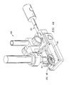
- FIGS. 3A-3B an example configuration of a preferred embodiment of the present invention is shown. That is, FIGS. 3A-3B show at least a portion of a manipulation system of a preferred embodiment, which includes a sample holder 300 .
- the example configuration of sample holder 300 shown in FIG. 3A comprises a first portion 301 and a second portion 302
- the first portion 301 cornprises a stage for receiving a sample (or “specimen”) to be studied, such as stage 430 shown more clearly in FIG. 4 B.
- the first portion 301 also comprises at least one manipulation mechanism that is controllably operable for manipulating a sample arranged on the stage.
- the first portion 301 comprises a plurality of manipulation mechanisms. For instance, an example configuration in which four manipulation mechanisms are included is shown more clearly in FIG. 4B (having manipulation mechanisms 410 A, 410 B, 410 C, and 410 D).
- first and second portions 301 and 302 provide an adaptable interface for sample holder 300 to enable such sample holder to be coupled to any of a plurality of different types of microscopes.
- portion 302 may preferably be removably coupled securely to portion 301 via coupling means 303 (which may be referred to herein as “adapting” means, as it allows the interface of sample holder 300 to be adapted to comply with various different microscope interfaces).
- portion 302 may screw onto the end of portion 301 , as shown in the example of FIG. 3 B.
- various other types of mechanical coupling mechanisms may be utilized in alternative embodiments.
- coupling means 303 may also provide an electrical coupling.
- coupling means 303 may include a multi-pin electrical connector that allows portion 301 to be communicatively coupled (e.g., electrically coupled) to a control system for controlling the operation of the manipulator mechanisms included in portion 301 (as described further below), or such multi-pin electrical connector may provide an electrical coupling to portion 302 which may in turn be communicatively coupled to such a control system for controlling the operation of the manipulator mechanisms of portion 301 .
- first portion 301 has a first length and when second portion 302 is coupled with portion 301 , sample holder 300 has a second length.
- the length of sample holder 300 may be adjusted (e.g., by coupling or uncoupling portions 301 and 302 ) to enable sample holder 300 to adaptively comply with any of various different microscope interfaces. For instance, commercially available TEMs have a sample chamber that requires a long sample holder than may be used with SEM sample chambers.
- portions 301 and 302 may be coupled together to enable sample holder 300 to interface with a TEM's sample chamber, and portion 301 may be uncoupled from portion 302 and such portion 301 may then interface with an SEM-s sample chamber. Accordingly, in this example configuration, once uncoupled from portion 302 , portion 301 becomes a fully functional and independent unit.
- portion 301 provides a first interface for coupling with a first type of microscope (e.g., an SEM microscope with a sample chamber having an interface for receiving a sample holder of a first length), and second portion 302 may be coupled to portion 301 to provide a second interface for coupling with a second type of microscope (e.g., a TEM microscope with a sample chamber having an interface for receiving a sample holder of a second length).
- a first type of microscope e.g., an SEM microscope with a sample chamber having an interface for receiving a sample holder of a first length
- second portion 302 may be coupled to portion 301 to provide a second interface for coupling with a second type of microscope (e.g., a TEM microscope with a sample chamber having an interface for receiving a sample holder of a second length).
- a second type of microscope e.g., a TEM microscope with a sample chamber having an interface for receiving a sample holder of a second length
- the length 1 1 of first portion 301 is approximately 10 cm, and the length 1 2 of portion 302 is approximately 24 cm.
- the overall length L 1 of sample holder 300 (when portions 301 and 302 are coupled) is approximately 34 cm.
- the diameter of sample holder 300 is preferably suitable for interfacing with the well-defined dimensions of sample commercially available TEM sample chambers.
- portion 301 comprises a suitable length 1 1 for interfacing with an SEM's sample chamber, and when coupled together, portions 301 and 302 provide a suitable length L 1 for interfacing with a TEM's sample chamber.
- sample holder 300 may differ from the example configuration described above to, for example, enable such sample holder 300 to interface with one or more desired types of microscopes, and any such alternative embodiment is intended to be within the scope of the present invention.
- sample holder 300 preferably comprises an adaptable interface. While the example configuration of FIGS. 3A-3B provides an adjustable interface that is adjusted by coupling or uncoupling portions of sample holder 300 , various other techniques may be employed in alternative embodiments for providing an adjustable interface in alternative embodiments.
- sample holder 300 may comprise a portion (e.g., portion 302 ) that is controllably expandible and contractable (in one or more dimensions, such as width (or diameter) and length) so as to adjust (or conform) to any of a plurality of different microscope interfaces.
- a user may place a sample on the stage 430 (see FIG. 4B ) of sample holder 300 , and may then couple sample holder 300 to one of a plurality of different types of microscopes. Thereafter, the manipulation mechanism(s) of sample holder 300 may be used to manipulate the sample as such sample is being imaged by the microscope.
- sample holder 300 may, in certain instances, be coupled to a light microscope 400 , and an external manipulation mechanism (i.e., external to sample holder 300 ), such as manipulation mechanism 402 , may be utilized to initially arrange the manipulation mechanisms of sample holder 300 . For example, as shown in FIG.
- sample holder 300 may be coupled to a platform 401 that comprises external manipulation mechanism 402 coupled therewith.
- external manipulation mechanism 402 may comprise an end-effector 403 , such as a gripper, that may be controlled to engage and arrange the internal manipulation mechanism(s) of sample holder 300 .
- sample holder 300 comprises four manipulation mechanisms 410 A, 410 B, 410 C, and 410 D (referred to collectively herein as manipulation mechanisms 410 ).
- External manipulation mechanism 402 may use end-effector 403 to perform relatively coarse adjustment of internal manipulation mechanisms 410 .
- a sample may be arranged on stage 430 of sample holder 300 , and while viewing the manipulation mechanisms 410 through light microscope 400 , a user may control external manipulation mechanism 402 to cause end-effector 403 to engage one or more of the internal manipulation mechanisms 410 and perform relatively coarse adjustment of the positioning of such manipulation mechanisms 410 relative to the sample.
- Each of manipulation mechanisms 410 may comprise an end-effector, such as a probe, gripper, etc., and adjustment mechanism 402 maybe used to adjust such end-effector to an initial position relative to the sample. While adjustment mechanism 402 may provide a relatively large travel range to a manipulation mechanism 410 in one or more dimensions (preferably in three dimensions), it may not be as precise in its positioning of such manipulation mechanism 410 as the below-described internal actuators of sample holder 300 . For instance, adjustment mechanism 402 may be capable of providing a relatively large range of movement to a manipulation mechanism 410 (e.g., several millimeters) with resolution of approximately 30 nanometers. Thus, such adjustment mechanism 402 may be used to initially position the end-effectors of manipulator mechanisms 410 to within approximately 30 nanometers of a desired position.
- adjustment mechanism 402 may provide a relatively large travel range to a manipulation mechanism 410 in one or more dimensions (preferably in three dimensions), it may not be as precise in its positioning of such manipulation mechanism 410 as the below-described internal actuators of sample
- one or more of the internal manipulation mechanisms 410 comprise an actuation mechanism for performing more fine/precise positioning of such internal manipulation mechanisms 410 end-effectors.
- manipulation mechanisms 410 A, 4 l 0 B, and 410 C are coupled to piezoelectric tubes 420 A, 420 B, and 420 C, respectively, such that piezoelectric tubes 420 A, 420 B, and 420 C can impart movement to their respective manipulation mechanism for precise positioning thereof.
- manipulation mechanisms 410 A, 410 B, and 410 C are controllably moveable (using piezoelectric tubes 420 A, 420 B, and 420 C), and manipulation mechanism 410 D is stationary.
- manipulation mechanism 410 D may also be coupled to an actuation mechanism such that it is also moveable.
- Piezoelectric tubes 420 A, 420 B, and 420 C preferably comprise quadruple electroded piezoelectric tubes that provide precise movement of a manipulation mechanism (e.g., its end-effector) in free space in the range of a few microns with nanometer resolution (or better, e.g., sub-nanometer resolution).
- a manipulation mechanism e.g., its end-effector
- nanometer resolution or better, e.g., sub-nanometer resolution
- such well-known actuators as a piezostack, a piezo bimorph, or a simple piezo plate, as examples, may be used if such fine translation of the manipulation mechanism is needed in only one dimension.
- a stick-slip type piezoelectric rotational actuator may be implemented for one or more of the manipulation mechanisms, and such piezoelectric rotational actuator may preferably be operated in continuous 360 degree rotation with an angular step resolution of less than 0.02 degree.
- piezoelectric tubes 420 A, 420 B, and 420 C are well-known in the art and therefore are not described in greater detail herein. It should be understood that while piezoelectric tubes are shown in the example configuration of FIG.
- any other suitable actuation mechanism may be utilized, including without limitation thermal microactuators, electrostatic microactuators, stick-slip piezoelectric micro actuators, piezo bimorph microactuators, comb drive microelectromechanical system (MEMS) actuators, and memory alloy microactuators
- thermal microactuators e.g., a TEM
- electrostatic microactuators e.g., a TEM
- stick-slip piezoelectric micro actuators e.g., piezo bimorph microactuators
- comb drive microelectromechanical system (MEMS) actuators comb drive microelectromechanical system (MEMS) actuators
- MEMS microelectromechanical system
- memory alloy microactuators e.g., size constraints for suitably interfacing with a particular type of microscope (e.g., a TEM) in certain embodiments may limit the types of actuation mechanisms that are suitable for implementation within sample holder 300 (e.g., may limit the suitable actuation mechanisms to micro-scale
- a plurality of manipulator mechanisms 410 may be included within the sample holder 300 . That is, by using an adjustment mechanism 402 that is external (or independent from) sample holder 300 for performing the coarse adjustment of manipulator mechanisms 410 to initially position such manipulator mechanisms, a plurality of manipulator mechanisms 410 may be implemented with high-precision actuators for controlling such manipulator mechanisms 410 within sample holder 300 .
- a plurality of manipulator mechanisms 410 that comprise high-precision actuators that are independently operable for controlling the movement of their respective manipulator mechanism may be implemented within even a relatively small sample holder, such as a sample holder that is sufficiently small for interfacing with a sample chamber of commercially available TEMs.
- detachable sample holders that include a manipulator mechanism have been developed in the existing art that are capable of being removably coupled to a TEM. Such detachable sample holders have been limited to including only one manipulator mechanism (e.g., end-effector) therein. Further, because such detachable sample holders of the existing art have included both a coarse adjustment mechanism and a high- precision adjustment mechanism, each for imparting movement to the manipulator mechanism's end-effector, only one manipulator mechanism has been recognized in such configurations.
- manipulator mechanism e.g., end-effector
- sample holder 300 comprises an adjustable interface that enables sample holder 300 to conform to any of a plurality of different microscope interfaces.
- sample holder 300 is capable of detachably coupling with at least one type of microscope (e.g., a TEM and/or SEM) and comprises a plurality of manipulator mechanisms integrated therein that are controllably operable for manipulating a sample under study with such microscope.
- at least one type of microscope e.g., a TEM and/or SEM
- sample holder 300 comprises both an adjustable interface such that it is capable of selectively coupling with any of a plurality of different microscope interfaces (e.g., either a TEM or an SEM interface) and a plurality of manipulator mechanisms integrated therein that are controllably operable for manipulating a sample under study with such microscope.
- sample holder 300 may be implemented to comprise an adjustable interface without necessarily comprising a plurality of manipulator mechanisms, and in certain embodiments, sample holder 300 may comprise a plurality of manipulator mechanisms integrated therein without necessarily comprising an adjustable microscope interface.
- sample holder 300 comprises an adjustable interface that enables sample holder 300 to conform to any of a plurality of different microscope interfaces.
- TEMs and SEMs generally comprise a sample chamber having an interface for receiving a sample holder, and the sample chamber interface for TEMs and SEMs is generally different.
- FIG. 5 shows a preferred embodiment of the present invention coupled with a TEM 100 . As shown, portion 301 comprising a sample stage 430 and at least one manipulation mechanism 410 is inserted into sample chamber 115 of TEM 100 .
- sample holder 300 has portion 302 coupled thereto such that it complies with sample chamber 115 (e.g., has the appropriate length for presenting a sample on sample stage 430 to be imaged by TEM 100 ). Accordingly, once inserted into sample chamber 115 , TEM 100 may be used to image a sample arranged on sample stage 430 and/or manipulation mechanism(s) 410 may be controlled to manipulate such sample.
- sample holder 300 may be communicatively coupled to a control system 501 .
- Control system 501 is preferably a processor-based device, such as a personal computer, that is operable to generate control signals to be communicated to actuators 420 A, 420 B, and 420 C in order to control their operation to impart desired movement to manipulator mechanism(s).
- Such control signals may, for example, be generated by control system 501 in response to user input thereto (e.g., user-input instructions requesting a particular operation of manipulator mechanism(s) 410 ). For instance, as shown in the example configuration of FIG.
- one end of portion 302 of sample holder 300 may be mechanically and electrically connected to portion 301 , and the opposing end of portion 302 may be communicatively (e.g., electrically) coupled to control system 501 .
- a multi-pin electrical connector may be used to electrically couple control system 501 to portion 302 in order to communicate control signals thereto for controlling the operation of manipulator mechanisms 410 of sample holder 300 .
- FIG. 6 shows a preferred embodiment coupled with an SEM.
- portion 301 comprising a sample stage 430 and at least one manipulation mechanism 410 is inserted into sample chamber 214 of the SEM.
- sample holder 300 has portion 302 uncoupled therefrom such that it complies with sample chamber 214 (e.g., is of appropriate length to enable sample holder 300 to be presented to such sample chamber in an appropriate manner for imaging a sample arranged on sample stage 430 ).
- the SEM may be used to image a sample arranged on sample stage 430 and/or manipulation mechanism(s) 410 may be controlled to manipulate such sample.
- sample holder 300 may be coupled to a platform 401 , and such platform 401 having sample holder 300 coupled thereto may be presented to sample chamber 214 of an SEM. That is, platform 401 may aid sample holder 300 in properly interfacing with the sample chamber 214 of an SEM. It should be recognized that sample holder 300 may also be coupled to such a platform 401 , as shown in FIG. 4A , and an external adjustment mechanism 402 may be coupled to such platform 401 and used to initially adjust the sample holder's manipulator mechanisms 410 .
- such an external adjustment mechanism 402 may be detachably coupled to platform 401 such that it can be removed from the platform 401 and such platform 401 maybe inserted into an SEM's sample chamber.
- Such platform 401 may be of a size similar to that of traditional SEM sample holder's, and it may therefore aid in properly aligning sample holder 300 within an SEM's sample chamber 214 properly for imaging a sample on sample stage 430 with such SEM.
- such platform 401 may be maintained in an SEM's sample chamber and sample holder 300 may be coupled therewith via the platform's interface 601 to image and/or manipulate a sample, and sample holder 300 may be uncoupled from such platform's interface 601 in order to remove the sample holder 300 from the SEM's sample chamber 214 (as opposed to inserting and removing the platform 401 from the SEM's sample chamber 214 each time that a sample is presented and removed from the SEM).
- sample holder 300 may be presented directly to an SEM's sample chamber 214 without using such a platform 401 , and any such implementation is intended to be within the scope of the present invention.
- sample holder 300 may be communicatively coupled to a control system 501 .
- control system 501 is briefly described above.
- one end of portion 301 of sample holder 300 may be communicatively (e.g., electrically) coupled to control system 501 .
- portion 301 itself may comprise a suitable interface for communicatively coupling with control system 501 .
- a multi-pin electrical connector may be used to electrically couple control system 501 to portion 301 in order to communicate control signals thereto for controlling the operation of manipulator mechanisms 410 of sample holder 300 .
- a sample holder 300 that comprises at least one manipulation mechanism and an adjustable interface to enable such sample holder 300 to be selectively coupled to any of a plurality of different types of microscopes. That is, in certain embodiments, sample holder 300 comprises at least one manipulation mechanism for manipulating a sample and an interface that that is adaptable to conform to a plurality of different types of microscope interfaces. More specifically, in at least one embodiment, sample holder 300 may be selectively coupled to either a TEM or an SEM.
- sample holder 300 can be detachably coupled to a microscope in a manner that does not interfere with normal operation (e.g., imaging functionality) of such microscope. Rather, sample holder 300 may be used solely for imaging a sample, if so desired, without using the manipulation mechanism(s) 410 for manipulating such sample.
- a traditional sample holder may be interchangeably used when only imaging of a sample is desired. That is, sample holder 300 is preferably implemented such that it can be used interchangeably with traditional sample holders of a microscope, as such sample holder 300 is preferably not required to be integrated with a microscope or require other modifications to a microscope that interfere with the microscope's normal functionality.
- certain embodiments provide a portable sample holder 300 that comprises integrated manipulation mechanism(s) 410 , wherein such sample holder 300 may be removably coupled to a microscope to provide manipulation capabilities (such as those described further herein below) when so desired.
- FIG. 7 shows an example block diagram of at least one embodiment of the present invention, wherein sample holder 300 comprises manipulator mechanism(s) 410 and interface 300 A for interfacing with a microscope.
- control system 501 such as is briefly described above, is communicatively coupled to manipulator mechanism(s) 410 .
- control system 501 may be utilized to control the operation of actuation mechanisms 420 A, 420 B, and 420 C to precisely position manipulator mechanism(s) (or “end-effeetors”) 410 . That is, such control system 501 may be used to control the manipulator mechanism(s) 410 in order to manipulate a sample under study.
- sample holder 300 may be coupled to a microscope, such as microscope 701 or microscope 702 of FIG. 7 , and control system 501 may be utilized to control actuators 420 A, 420 B, and 420 C to precisely move one or more of manipulator mechanism(s) (or “end-effectors”) 410 in order to manipulate a sample being imaged by such microscope.
- a microscope such as microscope 701 or microscope 702 of FIG. 7
- control system 501 may be utilized to control actuators 420 A, 420 B, and 420 C to precisely move one or more of manipulator mechanism(s) (or “end-effectors”) 410 in order to manipulate a sample being imaged by such microscope.
- interface 300 A of sample holder 300 is preferably adaptable to enable sample holder 300 to conform to a plurality of different microscope interfaces.
- interface 300 A may be adapted to conform with an interface 701 A of a first type of microscope 701 , such that sample holder 300 may be coupled to such microscope 701 to enable imaging and/or manipulation of a sample arranged in such sample holder 300 .
- interface 300 A may be adapted to coiiform with a different interface 702 A of a second type of microscope 702 , such that sample holder 300 may be coupled to such microscope 702 to enable imaging and/or manipulation of a sample arranged in such sample holder 300 .
- microscope 701 may, in certain embodiments, comprise a TEM and microscope 702 may comprise an SEM, and adaptable interface 300 A may enable sample holder 300 to be selectively coupled to either of such microscopes 701 and 702 .
- FIG. 8 an operational flow diagram is shown that illustrates an example of how certain embodiments of the present invention may be utilized. More specifically, FIG. 8 shows an example operational flow diagram for using a microscope to study a sample in accordance with certain embodiments of the present invention.
- a user selects a desired type of microscope. That is, operational block 801 comprises a user selecting a desired type of a plurality of different types of microscopes. Each of such plurality of different types of microscopes may have a different type of interface for receiving a sample holder.
- the user adjusts the interface of a sample holder to conform to the microscope's interface.
- operational block 802 comprises a user adjusting an interface of a sample holder to conform to the interface of the desired type of microscope.
- the sample holder's interface is preferably adjustable to conform to any of a plurality of different types of microscope interfaces for receiving a sample holder.
- a user arranges a sample on the sample holder.
- the sample holder is interfaced with the desired type of microscope such that the sample can be imaged by such desired type of microscope.
- the desired type of microscope may be used to image the sample arranged on the sample holder.
- manipulating mechanisms integrated within the sample holder e.g., manipulating mechanisms 410 of sample holder 300 ) may be used to manipulate the sample.
- sample holder 300 is capable of being detachably coupled to a microscope and comprises a plurality of manipulator mechanisms.
- FIG. 9 an operational flow diagram is shown that illustrates an example of how certain embodiments of the present invention may be utilized.
- a sample is arranged on a sample stage 430 of sample holder 300 , which comprises a plurality of manipulator mechanisms 410 .
- an adjustment mechanism e.g., adjustment mechanism 402 of FIG. 4A
- an adjustment mechanism that is independent from sample holder 300 is used to perform coarse adjustment of the manipulator mechanisms 410 in order to arrange each of their end-effectors to an initial position.
- sample holder 300 is interfaced to a microscope such that the sample arranged on sample stage 430 can be imaged by the microscope.
- the interface of sample holder 300 may be adjustable to enable it to conform to any of a plurality of different microscope interfaces (e.g., to a TEM's sample chamber and an SEM's sample chamber), and in other embodiments, the interfaced of sample holder 300 may not be so adjustable (e.g., it may be fixed).
- the internal actuators e.g., actuators 420 A, 420 B, and 420 C
- the internal actuators e.g., actuators 420 A, 420 B, and 420 C
- control system 501 the internal actuators of sample holder 300 are utilized (e.g., via control system 501 ) to perform precise movement of at least one of the manipulator mechanisms' end-effectors to a desired position.
- sample holder 300 comprises an adaptable interface that enables such sample holder 300 to be coupled to any of a plurality of different types of microscope interfaces. However, in certain other embodiments, sample holder 300 may not comprise such an adaptable interface.
- sample holder 300 is capable of being detachably coupled to a microscope and comprises a plurality of manipulator mechanisms. Preferably, each of such manipulator mechanisms is independently moveable by a corresponding actuator included within the sample holder 300 . In a preferred embodiment, such as in the example configuration of sample holder 300 described above in conjunction with FIGS.
- sample holder 300 comprises both an adjustable interface such that it is capable of selectively coupling with any of a plurality of different microscope interfaces (e.g., either a TEM or an SEM interface) and a plurality of manipulator mechanisms integrated therein that are controllably operable for manipulating a sample under study with such microscope.
- a plurality of different microscope interfaces e.g., either a TEM or an SEM interface
- manipulator mechanisms integrated therein that are controllably operable for manipulating a sample under study with such microscope.
- manipulation mechanisms 410 are shown herein (e.g., in FIG. 4B ) as probes in this example configuration of sample holder 300 , it should be understood that various other types of manipulation mechanisms may be implemented instead of or in addition to probes.
- manipulation mechanisms or “end-effectors” as grippers, glass fibers, hypodermic needles, hoses, and nanometer-scale hooks, may be implemented in place of one or more of the manipulation mechanisms 410 of sample holder 300 to enable various different types of manipulation operations to be performed on a sample under study.
- such manipulation mechanisms 410 may be interchangeable.
- a probe may be interchangeable within sample holder 300 with a gripper (or other type of manipulation mechanism) to enable a user to selectively configure sample holder 300 with the desired types of manipulation mechanisms for performing a desired manipulation operation on a sample under study.
- a universal adapter may be coupled to each of piezoelectric tubes 420 A- 420 C, and any manipulation mechanism complying with the interface to such universal adapter may be interchangeably used within sample holder 300 .
- sample holder 300 preferably comprises a plurality of manipulation mechanisms implemented therein. Most preferably, at least four manipulation mechanisms are implemented within such sample holder 300 . Having a plurality of manipulation mechanisms enables various types of measurements to be acquired for a sample under study. Certain embodiments of the present invention enable measurements that have traditionally been unavailable because of an insufficient number of manipulation mechanisms being implemented for a microscope's manipulation system.
- conductivity measurement can be performed on a nanometer-scale section of a sample either placed on the surface of sample stage 430 or suspended in free space by positioning two probes on the surface of the sample (i.e., using two probes to hold the sample in free space and one or more other probes to acquire measurements of sample).
- conductive and sharp probes such as etched conductive W, Pt, Au probes, implemented as an end-effector
- conductivity measurement can be performed on a nanometer-scale section of a sample either placed on the surface of sample stage 430 or suspended in free space by positioning two probes on the surface of the sample (i.e., using two probes to hold the sample in free space and one or more other probes to acquire measurements of sample).
- a four-probe kelvin conductivity measurement can be conducted down to the nanometer-scale on samples under study.
- One advantage of a four-probe conductivity measurement is that the contact resistance effect intrinsic to the formed interface between the probe and the sample can be neutralized, and the exact conductance of the sample can be obtained, which is not possible for two or three probe conductivity measurement.
- end-effectors such as force probes, force measurement or combined force/electrical measurement can also be realized down to the nanometer-scale.
- embodiments of the present invention enable various other types of measurements and/or characterizations to be acquired for a sample.
- manipulation system of certain embodiments of the present invention may be utilized to perform assembly operations on micro- and/or nano-scale objects.
- a plurality of samples may be arranged on stage 430 , and manipulation mechanisms 410 may, in certain applications, be used to assemble such samples into a desired structure.
- manipulation mechanisms 410 may, in certain applications, be used to assemble such samples into a desired structure.
- various other applications of such a manipulation system will be recognized by those of ordinary skill in the art.
Abstract
Description
Claims (64)
Priority Applications (6)
| Application Number | Priority Date | Filing Date | Title |
|---|---|---|---|
| US10/173,542 US6967335B1 (en) | 2002-06-17 | 2002-06-17 | Manipulation system for manipulating a sample under study with a microscope |
| EP03736728A EP1520200A1 (en) | 2002-06-17 | 2003-05-29 | Manipulation system for manipulating a sample under study with a microscope |
| AU2003237262A AU2003237262A1 (en) | 2002-06-17 | 2003-05-29 | Manipulation system for manipulating a sample under study with a microscope |
| JP2004513823A JP2005530195A (en) | 2002-06-17 | 2003-05-29 | Manipulation system for microscopic observation sample manipulation |
| CN03814146.9A CN1662838A (en) | 2002-06-17 | 2003-05-29 | Manipulation system for manipulating a sample under study with a microscope |
| PCT/US2003/016695 WO2003107065A1 (en) | 2002-06-17 | 2003-05-29 | Manipulation system for manipulating a sample under study with a microscope |
Applications Claiming Priority (1)
| Application Number | Priority Date | Filing Date | Title |
|---|---|---|---|
| US10/173,542 US6967335B1 (en) | 2002-06-17 | 2002-06-17 | Manipulation system for manipulating a sample under study with a microscope |
Publications (1)
| Publication Number | Publication Date |
|---|---|
| US6967335B1 true US6967335B1 (en) | 2005-11-22 |
Family
ID=29733374
Family Applications (1)
| Application Number | Title | Priority Date | Filing Date |
|---|---|---|---|
| US10/173,542 Expired - Lifetime US6967335B1 (en) | 2002-06-17 | 2002-06-17 | Manipulation system for manipulating a sample under study with a microscope |
Country Status (6)
| Country | Link |
|---|---|
| US (1) | US6967335B1 (en) |
| EP (1) | EP1520200A1 (en) |
| JP (1) | JP2005530195A (en) |
| CN (1) | CN1662838A (en) |
| AU (1) | AU2003237262A1 (en) |
| WO (1) | WO2003107065A1 (en) |
Cited By (32)
| Publication number | Priority date | Publication date | Assignee | Title |
|---|---|---|---|---|
| US20050029467A1 (en) * | 2002-06-17 | 2005-02-10 | Zyvex Corporation | Modular manipulation system for manipulating a sample under study with a microscope |
| US20050184028A1 (en) * | 2004-02-23 | 2005-08-25 | Zyvex Corporation | Probe tip processing |
| US20050285034A1 (en) * | 2004-06-23 | 2005-12-29 | Maki Tanaka | Method and apparatus for measuring three-dimensional shape of specimen by using SEM |
| US20060289784A1 (en) * | 2005-05-30 | 2006-12-28 | Jeol Ltd. | Specimen holder for electron microscope |
| US7227140B2 (en) | 2003-09-23 | 2007-06-05 | Zyvex Instruments, Llc | Method, system and device for microscopic examination employing fib-prepared sample grasping element |
| US20070227273A1 (en) * | 2005-11-29 | 2007-10-04 | Drexel University | Integrated system for simultaneous inspection and manipulation |
| US7326293B2 (en) | 2004-03-26 | 2008-02-05 | Zyvex Labs, Llc | Patterned atomic layer epitaxy |
| US20080176332A1 (en) * | 2006-09-29 | 2008-07-24 | The Regents Of The University Of California | Systems and methods for identifying and disrupting cellular organelles |
| US20080204551A1 (en) * | 2006-10-17 | 2008-08-28 | O'connell Dan | Miniature microscope camera |
| US20080283768A1 (en) * | 2006-07-26 | 2008-11-20 | Fei Company | Transfer mechanism for transferring a specimen |
| US7550743B1 (en) * | 2007-03-23 | 2009-06-23 | Kla-Tencor Corporation | Chamberless substrate handling |
| US7550744B1 (en) * | 2007-03-23 | 2009-06-23 | Kla-Tencor Corporation | Chamberless substrate handling |
| US20090263947A1 (en) * | 2006-07-28 | 2009-10-22 | Alpha & Omega Semiconductor, Ltd. | Bottom source LDMOSFET structure and method |
| US20100025580A1 (en) * | 2008-08-01 | 2010-02-04 | Omniprobe, Inc. | Grid holder for stem analysis in a charged particle instrument |
| US7759656B1 (en) | 2006-03-01 | 2010-07-20 | South Bay Technology, Inc. | Dual air particle sample cassette and methods for using same |
| US20100320396A1 (en) * | 2009-06-18 | 2010-12-23 | Hitachi, Ltd. | Sample holder for electron microscope |
| US20120176475A1 (en) * | 2011-01-07 | 2012-07-12 | Zeta Instruments, Inc. | 3D Microscope Including Insertable Components To Provide Multiple Imaging And Measurement Capabilities |
| US8288737B1 (en) | 2007-04-23 | 2012-10-16 | South Bay Technology, Inc. | Ion sputter removal from thin microscopy samples with ions extracted from an RF generated plasma |
| US20130058751A1 (en) * | 2010-04-15 | 2013-03-07 | Mmi Ag | Micromanipulation system comprising a protective system for capillaries |
| US20130098145A1 (en) * | 2008-07-03 | 2013-04-25 | Hysitron Incorporated | Method of measuring an interaction force |
| US20130105706A1 (en) * | 2011-05-31 | 2013-05-02 | Beijing University Of Technology | Double Tilt Transmission Electron Microscope Sample Holder for In-Situ Measurement of Microstructures |
| WO2013126271A1 (en) * | 2012-02-21 | 2013-08-29 | Inscopix, Inc. | Systems and methods for utilizing microscopy |
| US20150166273A1 (en) * | 2013-11-11 | 2015-06-18 | Howard Hughes Medical Institute | Workpiece holder for workpiece transport apparatus |
| US9551743B2 (en) | 2006-07-18 | 2017-01-24 | Dcg Systems, Inc. | Apparatus and method for combined micro-scale and nano-scale C-V, Q-V, and I-V testing of semiconductor materials |
| US9709600B2 (en) | 2013-08-14 | 2017-07-18 | Fei Company | Circuit probe for charged particle beam system |
| USD794816S1 (en) * | 2013-10-24 | 2017-08-15 | Hitachi High-Technologies Corporation | Sample holder for an electron microscope |
| US9891280B2 (en) | 2013-06-24 | 2018-02-13 | Fei Efa, Inc. | Probe-based data collection system with adaptive mode of probing controlled by local sample properties |
| US10037865B2 (en) | 2015-09-14 | 2018-07-31 | Jordan University Of Science And Technology | System and method for providing real-time visual feedback to control multiple autonomous nano-robots |
| US20180284415A1 (en) * | 2017-03-29 | 2018-10-04 | Hikari Instruments, L.L.C. | Microscope Focusing Device |
| US10312050B2 (en) | 2012-10-04 | 2019-06-04 | Snu R&Db Foundation | Holder device for electron microscope |
| IT201800007349A1 (en) * | 2018-07-19 | 2020-01-19 | Multistage vacuum device with stage separation controlled by a shape memory alloy actuator | |
| US10539589B2 (en) | 2014-06-25 | 2020-01-21 | Fei Efa, Inc. | Through process flow intra-chip and inter-chip electrical analysis and process control using in-line nanoprobing |
Families Citing this family (10)
| Publication number | Priority date | Publication date | Assignee | Title |
|---|---|---|---|---|
| CA2551194A1 (en) * | 2006-06-23 | 2007-12-23 | Xinyu Liu | Mems-based nanomanipulators/nanopositioners |
| EP1883096A1 (en) * | 2006-07-26 | 2008-01-30 | FEI Company | Transfer mechanism for transferring a specimen |
| CN102253484B (en) * | 2011-06-07 | 2012-05-23 | 宁波湛京光学仪器有限公司 | Coaxial coarse/fine focusing structure for microscope platform adjustment |
| WO2014175074A1 (en) * | 2013-04-23 | 2014-10-30 | 株式会社日立ハイテクノロジーズ | Charged particle radiation device and specimen preparation method using said device |
| KR101407234B1 (en) | 2013-12-06 | 2014-06-13 | 한국기초과학지원연구원 | Liquid specimen holder of electron microscope and electron microscope using thereof |
| WO2015167369A1 (en) * | 2014-04-30 | 2015-11-05 | Teknikpatrullen Ab | Object holder and microscope arrangement for positioning of the object holder |
| DE102014110724B4 (en) | 2014-07-29 | 2016-09-01 | European Molecular Biology Laboratory | Manipulation container for cryo-microscopy |
| CN105225910B (en) * | 2015-09-25 | 2017-11-28 | 苏州大学 | Micro OS based on SEM |
| CN110108635B (en) * | 2019-05-11 | 2024-03-22 | 金华职业技术学院 | Single cell adhesion force measuring method |
| WO2022242152A1 (en) * | 2021-05-21 | 2022-11-24 | 南方科技大学 | Multi-specification microscope linkage analysis sample table for transmission electron microscope sample |
Citations (42)
| Publication number | Priority date | Publication date | Assignee | Title |
|---|---|---|---|---|
| US3134942A (en) | 1960-12-13 | 1964-05-26 | Richard E Rhodes | Multiple probe resistivity measuring apparatus with workpiece support means |
| US3535515A (en) | 1967-06-14 | 1970-10-20 | Us Navy | Ultrasonic apparatus for electron microscope |
| US3714423A (en) | 1970-05-22 | 1973-01-30 | Ass Elect Ind | Specimen stages for electron microscopes |
| US4463257A (en) * | 1982-08-05 | 1984-07-31 | Tracor Xray Inc. | Rotatable support for selectively aligning a window with the channel of a probe |
| US4587431A (en) | 1983-04-22 | 1986-05-06 | Jeol Ltd. | Specimen manipulating mechanism for charged-particle beam instrument |
| US4601551A (en) | 1984-01-23 | 1986-07-22 | The Micromanipulator Microscope Company, Inc. | Manipulation of embryos and ova |
| US4729646A (en) | 1986-05-15 | 1988-03-08 | Bausch & Lomb Incorporated | Multi-use microscope having modular construction of extruded parts |
| US4798989A (en) | 1986-09-26 | 1989-01-17 | Research Development Corporation | Scanning tunneling microscope installed in electron microscope |
| US4919001A (en) | 1987-10-09 | 1990-04-24 | Olympus Optical Co., Ltd. | Coarse/fine adjustment coaxial handle for feeding microscope stage |
| US5036205A (en) | 1988-11-18 | 1991-07-30 | Chaixmeca Sarl | Apparatus for the transfer and in-situ reactions under a controlled atmosphere, of specimens for transmissive electron microscopy |
| US5055680A (en) | 1990-04-03 | 1991-10-08 | Lk Technologies, Inc. | Scanning tunneling microscope |
| US5124645A (en) | 1991-04-24 | 1992-06-23 | The United States Of America As Represented By The Secretary Of The Air Force | Transmission electron microscope (TEM) power probe for in-situ viewing of electromigration and operation of an integrated circuit or microprocessor |
| US5225683A (en) | 1990-11-30 | 1993-07-06 | Jeol Ltd. | Detachable specimen holder for transmission electron microscope |
| US5237238A (en) | 1990-07-21 | 1993-08-17 | Omicron Vakuumphysik Gmbh | Adjusting device for microscopic movements |
| US5412503A (en) | 1992-08-27 | 1995-05-02 | U.S. Philips Corporation | Specimen holder for a particle beam optical apparatus |
| US5455420A (en) | 1994-07-12 | 1995-10-03 | Topometrix | Scanning probe microscope apparatus for use in a scanning electron |
| WO1996013724A1 (en) | 1994-10-28 | 1996-05-09 | Biomolecular Research Institute Ltd. | A sample holder |
| WO1996020495A2 (en) | 1994-12-28 | 1996-07-04 | Technische Universiteit Delft | Specimen holder for an electron microscope and device and method for mounting a specimen in an electron microscope |
| US5568004A (en) | 1992-09-07 | 1996-10-22 | Kleindiek; Stephan | Electromechanical positioning device |
| US5635836A (en) * | 1994-10-21 | 1997-06-03 | International Business Machines Corporation | Mechanical apparatus with rod, pivot, and translation means for positioning a sample for use with a scanning microscope |
| US5756997A (en) | 1996-03-04 | 1998-05-26 | General Nanotechnology, L.L.C. | Scanning probe/optical microscope with modular objective/probe and drive/detector units |
| US5922179A (en) | 1996-12-20 | 1999-07-13 | Gatan, Inc. | Apparatus for etching and coating sample specimens for microscopic analysis |
| US5939816A (en) | 1988-09-30 | 1999-08-17 | Rockwell International Corporation | Piezoelectric actuator |
| US6002136A (en) | 1998-05-08 | 1999-12-14 | International Business Machines Corporation | Microscope specimen holder and grid arrangement for in-situ and ex-situ repeated analysis |
| US6000280A (en) | 1995-07-20 | 1999-12-14 | Cornell Research Foundation, Inc. | Drive electrodes for microfabricated torsional cantilevers |
| WO2000010191A1 (en) | 1998-08-12 | 2000-02-24 | Gatan, Inc. | Double tilt and rotate specimen holder for a transmission electron microscope |
| US6127682A (en) | 1996-09-26 | 2000-10-03 | Jeol Ltd. | Scanning probe microscope and method of analyzing sample using same |
| US6127681A (en) | 1987-08-12 | 2000-10-03 | Olympus Optical Co., Ltd. | Scanning tunnel microscope |
| WO2001009965A1 (en) | 1999-07-30 | 2001-02-08 | Forschungszentrum Jülich GmbH | Micromanipulator with piezoelectric movement elements |
| US6198299B1 (en) | 1998-08-27 | 2001-03-06 | The Micromanipulator Company, Inc. | High Resolution analytical probe station |
| JP2001198896A (en) | 2000-01-19 | 2001-07-24 | Hitachi Ltd | Micro-manipulator for electron microscope |
| US6279389B1 (en) | 1998-11-05 | 2001-08-28 | Nanodevices, Inc. | AFM with referenced or differential height measurement |
| US20010044158A1 (en) | 2000-04-19 | 2001-11-22 | Yeaman Grant R. | Diagnostic assay for endometriosis |
| JP2002033366A (en) | 2000-07-13 | 2002-01-31 | Hitachi Ltd | Probe unit and sample manipulating device using the same |
| US6346710B1 (en) | 1998-08-31 | 2002-02-12 | Olympus Optical Co., Ltd. | Stage apparatus including displacement amplifying mechanism |
| WO2002016089A2 (en) | 2000-08-25 | 2002-02-28 | Danmarks Tekniske Universitet | Fabrication and application of nano-manipulators with induced growth |
| US20020064341A1 (en) | 2000-11-27 | 2002-05-30 | Fauver Mark E. | Micro-fabricated optical waveguide for use in scanning fiber displays and scanned fiber image acquisition |
| US6403968B1 (en) | 1998-07-06 | 2002-06-11 | Hitachi, Ltd. | Scanning electron microscope |
| US6452307B1 (en) | 1999-06-13 | 2002-09-17 | Nanofactory Instruments Ab | Device for micropositioning of an object |
| US6501289B1 (en) | 1999-03-11 | 2002-12-31 | Tokyo Electron Limited | Inspection stage including a plurality of Z shafts, and inspection apparatus |
| US6538254B1 (en) * | 1997-07-22 | 2003-03-25 | Hitachi, Ltd. | Method and apparatus for sample fabrication |
| US6583413B1 (en) | 1999-09-01 | 2003-06-24 | Hitachi, Ltd. | Method of inspecting a circuit pattern and inspecting instrument |
-
2002
- 2002-06-17 US US10/173,542 patent/US6967335B1/en not_active Expired - Lifetime
-
2003
- 2003-05-29 CN CN03814146.9A patent/CN1662838A/en active Pending
- 2003-05-29 EP EP03736728A patent/EP1520200A1/en not_active Withdrawn
- 2003-05-29 JP JP2004513823A patent/JP2005530195A/en active Pending
- 2003-05-29 AU AU2003237262A patent/AU2003237262A1/en not_active Abandoned
- 2003-05-29 WO PCT/US2003/016695 patent/WO2003107065A1/en not_active Application Discontinuation
Patent Citations (43)
| Publication number | Priority date | Publication date | Assignee | Title |
|---|---|---|---|---|
| US3134942A (en) | 1960-12-13 | 1964-05-26 | Richard E Rhodes | Multiple probe resistivity measuring apparatus with workpiece support means |
| US3535515A (en) | 1967-06-14 | 1970-10-20 | Us Navy | Ultrasonic apparatus for electron microscope |
| US3714423A (en) | 1970-05-22 | 1973-01-30 | Ass Elect Ind | Specimen stages for electron microscopes |
| US4463257A (en) * | 1982-08-05 | 1984-07-31 | Tracor Xray Inc. | Rotatable support for selectively aligning a window with the channel of a probe |
| US4587431A (en) | 1983-04-22 | 1986-05-06 | Jeol Ltd. | Specimen manipulating mechanism for charged-particle beam instrument |
| US4601551A (en) | 1984-01-23 | 1986-07-22 | The Micromanipulator Microscope Company, Inc. | Manipulation of embryos and ova |
| US4729646A (en) | 1986-05-15 | 1988-03-08 | Bausch & Lomb Incorporated | Multi-use microscope having modular construction of extruded parts |
| US4798989A (en) | 1986-09-26 | 1989-01-17 | Research Development Corporation | Scanning tunneling microscope installed in electron microscope |
| US6127681A (en) | 1987-08-12 | 2000-10-03 | Olympus Optical Co., Ltd. | Scanning tunnel microscope |
| US4919001A (en) | 1987-10-09 | 1990-04-24 | Olympus Optical Co., Ltd. | Coarse/fine adjustment coaxial handle for feeding microscope stage |
| US5939816A (en) | 1988-09-30 | 1999-08-17 | Rockwell International Corporation | Piezoelectric actuator |
| US5036205A (en) | 1988-11-18 | 1991-07-30 | Chaixmeca Sarl | Apparatus for the transfer and in-situ reactions under a controlled atmosphere, of specimens for transmissive electron microscopy |
| US5055680A (en) | 1990-04-03 | 1991-10-08 | Lk Technologies, Inc. | Scanning tunneling microscope |
| US5237238A (en) | 1990-07-21 | 1993-08-17 | Omicron Vakuumphysik Gmbh | Adjusting device for microscopic movements |
| US5225683A (en) | 1990-11-30 | 1993-07-06 | Jeol Ltd. | Detachable specimen holder for transmission electron microscope |
| US5124645A (en) | 1991-04-24 | 1992-06-23 | The United States Of America As Represented By The Secretary Of The Air Force | Transmission electron microscope (TEM) power probe for in-situ viewing of electromigration and operation of an integrated circuit or microprocessor |
| US5412503A (en) | 1992-08-27 | 1995-05-02 | U.S. Philips Corporation | Specimen holder for a particle beam optical apparatus |
| US5568004A (en) | 1992-09-07 | 1996-10-22 | Kleindiek; Stephan | Electromechanical positioning device |
| US5455420A (en) | 1994-07-12 | 1995-10-03 | Topometrix | Scanning probe microscope apparatus for use in a scanning electron |
| US5510615A (en) | 1994-07-12 | 1996-04-23 | Topometrix Corporation | Scanning probe microscope apparatus for use in a scanning electron microscope |
| US5635836A (en) * | 1994-10-21 | 1997-06-03 | International Business Machines Corporation | Mechanical apparatus with rod, pivot, and translation means for positioning a sample for use with a scanning microscope |
| WO1996013724A1 (en) | 1994-10-28 | 1996-05-09 | Biomolecular Research Institute Ltd. | A sample holder |
| WO1996020495A2 (en) | 1994-12-28 | 1996-07-04 | Technische Universiteit Delft | Specimen holder for an electron microscope and device and method for mounting a specimen in an electron microscope |
| US6000280A (en) | 1995-07-20 | 1999-12-14 | Cornell Research Foundation, Inc. | Drive electrodes for microfabricated torsional cantilevers |
| US5756997A (en) | 1996-03-04 | 1998-05-26 | General Nanotechnology, L.L.C. | Scanning probe/optical microscope with modular objective/probe and drive/detector units |
| US6127682A (en) | 1996-09-26 | 2000-10-03 | Jeol Ltd. | Scanning probe microscope and method of analyzing sample using same |
| US5922179A (en) | 1996-12-20 | 1999-07-13 | Gatan, Inc. | Apparatus for etching and coating sample specimens for microscopic analysis |
| US6538254B1 (en) * | 1997-07-22 | 2003-03-25 | Hitachi, Ltd. | Method and apparatus for sample fabrication |
| US6002136A (en) | 1998-05-08 | 1999-12-14 | International Business Machines Corporation | Microscope specimen holder and grid arrangement for in-situ and ex-situ repeated analysis |
| US6403968B1 (en) | 1998-07-06 | 2002-06-11 | Hitachi, Ltd. | Scanning electron microscope |
| WO2000010191A1 (en) | 1998-08-12 | 2000-02-24 | Gatan, Inc. | Double tilt and rotate specimen holder for a transmission electron microscope |
| US6198299B1 (en) | 1998-08-27 | 2001-03-06 | The Micromanipulator Company, Inc. | High Resolution analytical probe station |
| US6346710B1 (en) | 1998-08-31 | 2002-02-12 | Olympus Optical Co., Ltd. | Stage apparatus including displacement amplifying mechanism |
| US6279389B1 (en) | 1998-11-05 | 2001-08-28 | Nanodevices, Inc. | AFM with referenced or differential height measurement |
| US6501289B1 (en) | 1999-03-11 | 2002-12-31 | Tokyo Electron Limited | Inspection stage including a plurality of Z shafts, and inspection apparatus |
| US6452307B1 (en) | 1999-06-13 | 2002-09-17 | Nanofactory Instruments Ab | Device for micropositioning of an object |
| WO2001009965A1 (en) | 1999-07-30 | 2001-02-08 | Forschungszentrum Jülich GmbH | Micromanipulator with piezoelectric movement elements |
| US6583413B1 (en) | 1999-09-01 | 2003-06-24 | Hitachi, Ltd. | Method of inspecting a circuit pattern and inspecting instrument |
| JP2001198896A (en) | 2000-01-19 | 2001-07-24 | Hitachi Ltd | Micro-manipulator for electron microscope |
| US20010044158A1 (en) | 2000-04-19 | 2001-11-22 | Yeaman Grant R. | Diagnostic assay for endometriosis |
| JP2002033366A (en) | 2000-07-13 | 2002-01-31 | Hitachi Ltd | Probe unit and sample manipulating device using the same |
| WO2002016089A2 (en) | 2000-08-25 | 2002-02-28 | Danmarks Tekniske Universitet | Fabrication and application of nano-manipulators with induced growth |
| US20020064341A1 (en) | 2000-11-27 | 2002-05-30 | Fauver Mark E. | Micro-fabricated optical waveguide for use in scanning fiber displays and scanned fiber image acquisition |
Non-Patent Citations (5)
| Title |
|---|
| Fatikow, et al., "A Flexible Microrobot-Based Microassembly Station," Emerging Technologies and Factory Automation, 1999. Proceedings ETFA '99. 1999 7<SUP>th </SUP>IEEE International Conference, Barcelona, Spain 18-21 Oct. 1999, Piscataway, NJ USA, pp. 397-406. |
| Investment Approaches: Lux NanoSphere: Measurement, Nanotechnology, The Nanotech Report 2001, pp. 122-136. |
| Technical Data from Klocke Nanotechnik, Dr. Volker Klocke, Aachen, Germany, printed Nov. 2002, 85 pages. |
| U.S. appl. No. 10/173,543, Min-Feng Yu. |
| Yu, Minfeng, et al., "Three-dimensional manipulation of carbon nanotubes under a scanning electron microscope", 1999 IOP Publishing Ltd., pp. 244-252. |
Cited By (63)
| Publication number | Priority date | Publication date | Assignee | Title |
|---|---|---|---|---|
| US7220973B2 (en) * | 2002-06-17 | 2007-05-22 | Zyvex Corporation | Modular manipulation system for manipulating a sample under study with a microscope |
| US20050029467A1 (en) * | 2002-06-17 | 2005-02-10 | Zyvex Corporation | Modular manipulation system for manipulating a sample under study with a microscope |
| US20070187623A1 (en) * | 2003-09-23 | 2007-08-16 | Zyvex Instruments, Llc | Method, System and Device for Microscopic Examination Employing Fib-Prepared Sample Grasping Element |
| US7227140B2 (en) | 2003-09-23 | 2007-06-05 | Zyvex Instruments, Llc | Method, system and device for microscopic examination employing fib-prepared sample grasping element |
| US7319336B2 (en) | 2004-02-23 | 2008-01-15 | Zyvex Instruments, Llc | Charged particle beam device probe operation |
| US20050184028A1 (en) * | 2004-02-23 | 2005-08-25 | Zyvex Corporation | Probe tip processing |
| US20060192116A1 (en) * | 2004-02-23 | 2006-08-31 | Zyvex Corporation | Charged particle beam device probe operation |
| US7675300B2 (en) | 2004-02-23 | 2010-03-09 | Zyvex Instruments, Llc | Charged particle beam device probe operation |
| US7285778B2 (en) * | 2004-02-23 | 2007-10-23 | Zyvex Corporation | Probe current imaging |
| US20050184236A1 (en) * | 2004-02-23 | 2005-08-25 | Zyvex Corporation | Probe current imaging |
| US7326293B2 (en) | 2004-03-26 | 2008-02-05 | Zyvex Labs, Llc | Patterned atomic layer epitaxy |
| US7799132B2 (en) | 2004-03-26 | 2010-09-21 | Zyvex Labs, Llc | Patterned atomic layer epitaxy |
| US7230243B2 (en) * | 2004-06-23 | 2007-06-12 | Hitachi High-Technologies Corporation | Method and apparatus for measuring three-dimensional shape of specimen by using SEM |
| US20050285034A1 (en) * | 2004-06-23 | 2005-12-29 | Maki Tanaka | Method and apparatus for measuring three-dimensional shape of specimen by using SEM |
| US7566884B2 (en) * | 2005-05-30 | 2009-07-28 | Jeol Ltd. | Specimen holder for electron microscope |
| US20060289784A1 (en) * | 2005-05-30 | 2006-12-28 | Jeol Ltd. | Specimen holder for electron microscope |
| US20070227273A1 (en) * | 2005-11-29 | 2007-10-04 | Drexel University | Integrated system for simultaneous inspection and manipulation |
| US7647848B2 (en) | 2005-11-29 | 2010-01-19 | Drexel University | Integrated system for simultaneous inspection and manipulation |
| US7759656B1 (en) | 2006-03-01 | 2010-07-20 | South Bay Technology, Inc. | Dual air particle sample cassette and methods for using same |
| US9551743B2 (en) | 2006-07-18 | 2017-01-24 | Dcg Systems, Inc. | Apparatus and method for combined micro-scale and nano-scale C-V, Q-V, and I-V testing of semiconductor materials |
| US20080283768A1 (en) * | 2006-07-26 | 2008-11-20 | Fei Company | Transfer mechanism for transferring a specimen |
| US7888655B2 (en) | 2006-07-26 | 2011-02-15 | Fei Company | Transfer mechanism for transferring a specimen |
| US20090263947A1 (en) * | 2006-07-28 | 2009-10-22 | Alpha & Omega Semiconductor, Ltd. | Bottom source LDMOSFET structure and method |
| US9321990B2 (en) | 2006-09-29 | 2016-04-26 | The Regents Of The University Of California | Systems and methods for identifying and disrupting cellular organelles |
| US20080176332A1 (en) * | 2006-09-29 | 2008-07-24 | The Regents Of The University Of California | Systems and methods for identifying and disrupting cellular organelles |
| US8624967B2 (en) * | 2006-10-17 | 2014-01-07 | Dan O'Connell | Integrated portable in-situ microscope |
| US20080204551A1 (en) * | 2006-10-17 | 2008-08-28 | O'connell Dan | Miniature microscope camera |
| US7550743B1 (en) * | 2007-03-23 | 2009-06-23 | Kla-Tencor Corporation | Chamberless substrate handling |
| US7550744B1 (en) * | 2007-03-23 | 2009-06-23 | Kla-Tencor Corporation | Chamberless substrate handling |
| US8742346B1 (en) | 2007-04-23 | 2014-06-03 | South Bay Technology, Inc. | Sputter removal of material from microscopy samples with RF generated plasma |
| US8288737B1 (en) | 2007-04-23 | 2012-10-16 | South Bay Technology, Inc. | Ion sputter removal from thin microscopy samples with ions extracted from an RF generated plasma |
| US9335240B2 (en) * | 2008-07-03 | 2016-05-10 | Hysitron Incorporated | Method of measuring an interaction force |
| US20130098145A1 (en) * | 2008-07-03 | 2013-04-25 | Hysitron Incorporated | Method of measuring an interaction force |
| US20100025580A1 (en) * | 2008-08-01 | 2010-02-04 | Omniprobe, Inc. | Grid holder for stem analysis in a charged particle instrument |
| US8338798B2 (en) * | 2009-06-18 | 2012-12-25 | Hitachi, Ltd. | Sample holder for electron microscope |
| US20100320396A1 (en) * | 2009-06-18 | 2010-12-23 | Hitachi, Ltd. | Sample holder for electron microscope |
| US20130058751A1 (en) * | 2010-04-15 | 2013-03-07 | Mmi Ag | Micromanipulation system comprising a protective system for capillaries |
| US20120176475A1 (en) * | 2011-01-07 | 2012-07-12 | Zeta Instruments, Inc. | 3D Microscope Including Insertable Components To Provide Multiple Imaging And Measurement Capabilities |
| US11536940B2 (en) | 2011-01-07 | 2022-12-27 | Kla-Tencor Corporation | 3D microscope including insertable components to provide multiple imaging and measurement capabilities |
| US11294161B2 (en) | 2011-01-07 | 2022-04-05 | Kla-Tencor Corporation | 3D microscope including insertable components to provide multiple imaging and measurement capabilities |
| US10048480B2 (en) * | 2011-01-07 | 2018-08-14 | Zeta Instruments, Inc. | 3D microscope including insertable components to provide multiple imaging and measurement capabilities |
| US10884228B2 (en) | 2011-01-07 | 2021-01-05 | Kla-Tencor Corporation | 3D microscope including insertable components to provide multiple imaging and measurement capabilities |
| US20130105706A1 (en) * | 2011-05-31 | 2013-05-02 | Beijing University Of Technology | Double Tilt Transmission Electron Microscope Sample Holder for In-Situ Measurement of Microstructures |
| US8569714B2 (en) * | 2011-05-31 | 2013-10-29 | Beijing University Of Technology | Double tilt transmission electron microscope sample holder for in-situ measurement of microstructures |
| WO2013126271A1 (en) * | 2012-02-21 | 2013-08-29 | Inscopix, Inc. | Systems and methods for utilizing microscopy |
| US10312050B2 (en) | 2012-10-04 | 2019-06-04 | Snu R&Db Foundation | Holder device for electron microscope |
| US9891280B2 (en) | 2013-06-24 | 2018-02-13 | Fei Efa, Inc. | Probe-based data collection system with adaptive mode of probing controlled by local sample properties |
| US9709600B2 (en) | 2013-08-14 | 2017-07-18 | Fei Company | Circuit probe for charged particle beam system |
| USD794816S1 (en) * | 2013-10-24 | 2017-08-15 | Hitachi High-Technologies Corporation | Sample holder for an electron microscope |
| US9449785B2 (en) * | 2013-11-11 | 2016-09-20 | Howard Hughes Medical Institute | Workpiece transport and positioning apparatus |
| US10186397B2 (en) * | 2013-11-11 | 2019-01-22 | Howard Hughes Medical Institute | Workpiece holder for workpiece transport apparatus |
| US20150166273A1 (en) * | 2013-11-11 | 2015-06-18 | Howard Hughes Medical Institute | Workpiece holder for workpiece transport apparatus |
| US20150243473A1 (en) * | 2013-11-11 | 2015-08-27 | Howard Hughes Medical Institute | Workpiece transport and positioning apparatus |
| US10361060B2 (en) | 2013-11-11 | 2019-07-23 | Howard Hughes Medical Institute | Workpiece transport and positioning apparatus |
| US9601305B2 (en) | 2013-11-11 | 2017-03-21 | Howard Hughes Medical Institute | Specimen sample holder for workpiece transport apparatus |
| US10539589B2 (en) | 2014-06-25 | 2020-01-21 | Fei Efa, Inc. | Through process flow intra-chip and inter-chip electrical analysis and process control using in-line nanoprobing |
| US10037865B2 (en) | 2015-09-14 | 2018-07-31 | Jordan University Of Science And Technology | System and method for providing real-time visual feedback to control multiple autonomous nano-robots |
| US20180284415A1 (en) * | 2017-03-29 | 2018-10-04 | Hikari Instruments, L.L.C. | Microscope Focusing Device |
| US10234670B2 (en) * | 2017-03-29 | 2019-03-19 | Hikari Instruments, Llc | Microscope focusing device |
| WO2020016843A1 (en) | 2018-07-19 | 2020-01-23 | Saes Getters S.P.A. | Multi-stage vacuum equipment with stages separation controlled by shape memory alloy actuator |
| IT201800007349A1 (en) * | 2018-07-19 | 2020-01-19 | Multistage vacuum device with stage separation controlled by a shape memory alloy actuator | |
| CN112335011A (en) * | 2018-07-19 | 2021-02-05 | 工程吸气公司 | Multi-stage vacuum apparatus with stage separation controlled by shape memory alloy actuator |
| US11239041B2 (en) | 2018-07-19 | 2022-02-01 | Saes Getters S.P.A. | Multi-stage vacuum equipment with stages separation controlled by SMA actuator |
Also Published As
| Publication number | Publication date |
|---|---|
| JP2005530195A (en) | 2005-10-06 |
| EP1520200A1 (en) | 2005-04-06 |
| WO2003107065A1 (en) | 2003-12-24 |
| AU2003237262A1 (en) | 2003-12-31 |
| CN1662838A (en) | 2005-08-31 |
Similar Documents
| Publication | Publication Date | Title |
|---|---|---|
| US6967335B1 (en) | Manipulation system for manipulating a sample under study with a microscope | |
| US6891170B1 (en) | Modular manipulation system for manipulating a sample under study with a microscope | |
| US7777185B2 (en) | Method and apparatus for a high-resolution three dimensional confocal scanning transmission electron microscope | |
| US6369385B1 (en) | Integrated microcolumn and scanning probe microscope arrays | |
| EP1238405B1 (en) | Method and system for the examination of specimen using a charged particle beam | |
| JP2008270056A (en) | Scanning transmission electron microscope | |
| JP2011514641A (en) | Sample holder assembly | |
| JPH07335165A (en) | Electron microscope for observation of lattice fault | |
| JP2000188077A (en) | Scanning electron microscope | |
| KR20050021987A (en) | Manipulation system for manipulating a sample under study with a microscope | |
| Dombrowski | Microscopy techniques for analyzing the phase nature and morphology of biomaterials | |
| CN104122414B (en) | A kind of high stability scanning probe unit being applied in electron microscope | |
| JP2002150983A (en) | Manipulator | |
| JP2002279925A (en) | High-resolution compound microscope | |
| Shi | Transmission electron microscope | |
| Shah | Electron Microscopy: A versatile tool in nanoworld | |
| Renahy et al. | An Interactive micromanipulation station combined to a confocal XRF instrument: proof of concept | |
| Gajghate | Introduction to Microscopy | |
| Basu et al. | Preparation and Characterization of Nanoparticles | |
| Zhang et al. | Comparison of sequential light, scanning electron and atomic force examine methods for electron beam lithography generated patterns | |
| KR20060001036A (en) | Objective aperture for eliminating background noise of high resolution image | |
| Fukuda et al. | Nanomanipulation system under electron microscope | |
| Alam | 3.2 Scanning Electron Microscopy (SEM) | |
| CAIRNEY et al. | Electron Microscope Unit University of New South Wales | |
| JPS62119847A (en) | Charged beam device |
Legal Events
| Date | Code | Title | Description |
|---|---|---|---|
| AS | Assignment |
Owner name: ZYVEX CORPORATION, TEXAS Free format text: ASSIGNMENT OF ASSIGNORS INTEREST;ASSIGNORS:DYER, MARK J.;BRAY, KEN;YU, MIN-FENG;REEL/FRAME:013301/0355;SIGNING DATES FROM 20020808 TO 20020909 |
|
| STCF | Information on status: patent grant |
Free format text: PATENTED CASE |
|
| CC | Certificate of correction | ||
| AS | Assignment |
Owner name: SILICON VALLEY BANK,CALIFORNIA Free format text: SECURITY INTEREST;ASSIGNOR:ZYVEX CORPORATION;REEL/FRAME:017921/0368 Effective date: 20050929 Owner name: SILICON VALLEY BANK, CALIFORNIA Free format text: SECURITY INTEREST;ASSIGNOR:ZYVEX CORPORATION;REEL/FRAME:017921/0368 Effective date: 20050929 |
|
| AS | Assignment |
Owner name: ZYVEX CORPORATION, TEXAS Free format text: RELEASE;ASSIGNOR:SILICON VALLEY BANK;REEL/FRAME:018777/0003 Effective date: 20070105 |
|
| AS | Assignment |
Owner name: ZYVEX INSTRUMENTS, LLC, TEXAS Free format text: NUNC PRO TUNC ASSIGNMENT;ASSIGNOR:ZYVEX CORPORATION;REEL/FRAME:019353/0363 Effective date: 20070521 |
|
| CC | Certificate of correction | ||
| AS | Assignment |
Owner name: UNITED STATES DEPARTMENT OF ENERGY, DISTRICT OF CO Free format text: CONFIRMATORY LICENSE;ASSIGNOR:ZYVEX CORPORATION;REEL/FRAME:021858/0234 Effective date: 20080924 |
|
| FEPP | Fee payment procedure |
Free format text: PAYOR NUMBER ASSIGNED (ORIGINAL EVENT CODE: ASPN); ENTITY STATUS OF PATENT OWNER: LARGE ENTITY |
|
| FPAY | Fee payment |
Year of fee payment: 4 |
|
| AS | Assignment |
Owner name: DCG SYSTEMS, INC.,CALIFORNIA Free format text: ASSIGNMENT OF ASSIGNORS INTEREST;ASSIGNOR:ZYVEX INSTRUMENTS, LLC;REEL/FRAME:024368/0736 Effective date: 20100211 |
|
| FPAY | Fee payment |
Year of fee payment: 8 |
|
| FEPP | Fee payment procedure |
Free format text: PAT HOLDER NO LONGER CLAIMS SMALL ENTITY STATUS, ENTITY STATUS SET TO UNDISCOUNTED (ORIGINAL EVENT CODE: STOL); ENTITY STATUS OF PATENT OWNER: LARGE ENTITY |
|
| FPAY | Fee payment |
Year of fee payment: 12 |