US6978747B2 - Hydraulic actuator cartridge for a valve - Google Patents
Hydraulic actuator cartridge for a valve Download PDFInfo
- Publication number
- US6978747B2 US6978747B2 US10/404,482 US40448203A US6978747B2 US 6978747 B2 US6978747 B2 US 6978747B2 US 40448203 A US40448203 A US 40448203A US 6978747 B2 US6978747 B2 US 6978747B2
- Authority
- US
- United States
- Prior art keywords
- return
- actuation
- push plate
- valve actuator
- actuator cartridge
- Prior art date
- Legal status (The legal status is an assumption and is not a legal conclusion. Google has not performed a legal analysis and makes no representation as to the accuracy of the status listed.)
- Expired - Lifetime, expires
Links
Images


Classifications
-
- F—MECHANICAL ENGINEERING; LIGHTING; HEATING; WEAPONS; BLASTING
- F01—MACHINES OR ENGINES IN GENERAL; ENGINE PLANTS IN GENERAL; STEAM ENGINES
- F01L—CYCLICALLY OPERATING VALVES FOR MACHINES OR ENGINES
- F01L1/00—Valve-gear or valve arrangements, e.g. lift-valve gear
- F01L1/26—Valve-gear or valve arrangements, e.g. lift-valve gear characterised by the provision of two or more valves operated simultaneously by same transmitting-gear; peculiar to machines or engines with more than two lift-valves per cylinder
-
- F—MECHANICAL ENGINEERING; LIGHTING; HEATING; WEAPONS; BLASTING
- F01—MACHINES OR ENGINES IN GENERAL; ENGINE PLANTS IN GENERAL; STEAM ENGINES
- F01L—CYCLICALLY OPERATING VALVES FOR MACHINES OR ENGINES
- F01L9/00—Valve-gear or valve arrangements actuated non-mechanically
- F01L9/10—Valve-gear or valve arrangements actuated non-mechanically by fluid means, e.g. hydraulic
- F01L9/16—Pneumatic means
Definitions
- the present invention relates to a valve actuator useful in an internal combustion engine. More particularly, the invention relates to a hydraulic actuator for positively opening and closing an air valve.
- engine air valves are actuated by a cam shaft bearing on a poppet type valve stem and opening the valve by action of the eccentric cam lobe bearing on the valve stem acting counter to the bias of a closing valve spring. Closing of the valve is by means of the bias exerted by the valve spring.
- the present design involves high mass, takes up significant space, and is limited in the amount of variation in valve opening and closing profile that may be achieved to increase performance and minimize pollutant generation over a wide range of engine operating conditions. There is a need in the industry then to reduce the mass of the valve train, minimize the space occupied by the valve train and increase the flexibility of the achievable variation of the valve opening and closing profile.
- the present invention substantially meets the aforementioned needs of the industry.
- Valve train mass is substantially reduced along with a significant reduction in the space needed to house the valve train.
- Significantly, the flexibility of the valve profile to meet the needs of the engine across the full spectrum of engine operating conditions is greatly enhanced.
- the present invention is a valve actuator for controlling a valve between an open and a closed disposition and includes a coupling to a source of fluid under pressure and a coupling to a reservoir at substantially ambient pressure.
- a control is fluidly coupled to the source of fluid under pressure and to the reservoir for controlling presenting fluid at selected pressure to affect a reciprocatable component, the reciprocatable component being operably coupled to the valve for shifting the valve between the open and the closed disposition. And, positively, hydraulically shifting the valve between the open and the closed disposition.
- the present invention is further a method of valve actuation.
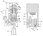
- FIG. 1 is a schematic depiction of the actuator cartridge of an embodiment of the present invention
- FIG. 2 is a detailed schematic depiction of the function of the mechanical damping mechanism of FIG. 1 ;
- FIG. 3 is a schematic depiction of the actuator cartridge of an embodiment of the present invention without the mechanical damping mechanism of FIGS. 1 and 2 ;
- FIG. 4 is an exploded perspective view of the actuator cartridge of FIGS. 1 and 2 ;
- FIG. 5 a is a top planform view of the actuator cartridge of FIGS. 1 and 2 with the return checks depicted in phantom and the actuator cartridge in the open disposition;
- FIG. 5 b is sectional view of the actuator cartridge taken along the section line B—B of FIG. 5 a;
- FIG. 5 c is sectional view of the actuator cartridge taken along the section line D—D of FIG. 5 a;
- FIG. 5 d is a top planform view of the actuator cartridge of FIGS. 1 and 2 with the return checks depicted in phantom and the actuator cartridge in the closed disposition;
- FIG. 5 e is sectional view of the actuator cartridge taken along the section line A—A of FIG. 5 d;
- FIG. 5 f is sectional view of the actuator cartridge taken along the section line C—C of FIG. 5 d;
- FIG. 6 a is a top planform view of the actuator cartridge of FIGS. 1 and 2 in relation to neighboring components in the engine head;
- FIG. 6 b is a sectional view taken along the section line B—B of FIG. 6 a;
- FIG. 6 c is a sectional view taken along the section line A—A of FIG. 6 a ;
- FIG. 6 b is a sectional view taken along the section line C—C of FIG. 6 a.
- the actuator cartridge of the present invention is shown generally at 10 in the figures.
- the actuator cartridge 10 includes a generally cylindrical housing 12 that may include a bottom housing 12 b mated to a top housing 12 a .
- a plurality of fluidly connected bores are defined in the housing 12 .
- the bores include a central push plate bore 14 .
- the push plate bore 14 is fluidly coupled to an area of ambient or near ambient pressure external to the actuator cartridge by a vent 16 .
- a plurality of pin bores, including return pin bores 18 and actuator pin bores 20 are in fluid communication with the push plate bore 14 .
- a push plate 22 is translatably disposed in the push plate bore 14 .
- the push plate 22 is mechanically attached to one of an array of internal combustion engine air valves 24 by bearing on the upper margin of the valve stem 26 .
- the air valve 24 (in practice, typically an intake or an exhaust valve) may be of the poppet valve design commonly used in internal combustion engines or the retracting seat design, illustrated in FIG. 1 and the subject of co-pending U.S. patent application Ser. No. 09/848516, filed May 3, 2001 incorporated herein by reference.
- the up-down translatory motion of the push plate 22 in the push plate bore 14 and of the air valve 22 is realized by applying hydraulic force via a multiplicity of cylindrical pins 26 located on opposed sides of the push plate 22 , the return pins 26 a being in contact with the push plate upper margin (return side) and the actuator pins 26 b being in contact with the push plate lower margin (actuator side).
- the pins 26 may, or may not be, mechanically attached to the push plate 22 . In the present embodiment however, the pins 26 are not mechanically attached to the push plate 22 in order to facilitate ease of assembly of the actuator cartridge 10 .
- the return pins 26 a on the return side of the push plate 22 are plumbed via ports 28 directly to a source of high-pressure hydraulic fluid 30 , commonly referred to as the ‘rail’.
- the pressure in the return chambers 32 (variable volume chambers 32 are defined in part by the return pin bores 18 and in part by the upper margin of the return pins 26 a ) remains fixed (assuming a constant fluid pressure in the rail 30 ) throughout the valve event (an event being a shifting of the valve 24 between a closed disposition to an open disposition and return to a closed disposition), providing for a constant downward force on the upper margin of the push plate 22 tending to bias the push plate 22 and the air valve 24 in the closed disposition.
- the push plate 22 is in the closed disposition when it is at its downwardmost disposition and is open when it is in its upwardmost disposition, corresponding to the open and closed dispositions of the air valve 24 .
- the actuation pins 26 b on the actuation side of the push plate 22 are plumbed via ports 34 to a control valve 36 , which may preferably be an electronically controlled 2p3w spool valve.
- the control valve 36 connects either high pressure fluid from the rail 30 to the actuation chambers 38 on the actuation side of the push plate 22 or connects the actuation chambers 38 to the ambient reservoir 40 , as desired.
- the actuation chambers 38 are variable volume being defined in part by the actuation pin bores 20 and in part by the upper margin of the actuation pins 26 b.
- the push plate 22 of the actuator cartridge 10 is constrained to move linearly between two stop limits, upper margin stop 42 of the push plate bore 14 and lower margin stop 44 of the push plate bore 14 .
- the full stroke of the push plate 22 between the two limits approximates the required stroke of the air valve 24 .
- the actuator cartridge 10 typically is of low mass when compared to prior art valve actuators, allowing for rapid actuation of the air valve 24 over the typical range of required air valve 24 motions needed for all operating conditions of the engine.
- the number and size of the pins 26 on either side of the push plate 22 are dictated by: (a) dynamic loads, (b) in-cylinder gas loads, and (c) ‘sealing’ forces required for the particular air valve 24 application.
- the total actuation pin 26 b wetted surface area exceeds the wetted surface area of the return pins 26 a (the area exposed to fluid pressure at the distal end 46 of the respective return pin 26 a ), providing a net hydraulic force either up or down, depending on the pressure state of the actuation chambers 38 , e.g. whether the chambers 38 are exposed to ambient pressure or to fluid pressure from the rail 30 .
- Seating velocity control for the air valve 24 may be accommodated either by use of a mechanical damping mechanism such as may be used in hydraulic applications, or via the control valve 36 .
- a suitable damping mechanism engages a short distance prior to the actuator impacting the mechanical safety stop (the push plate 22 coming to rest against either stop 42 or 44 ) in order to reduce actuator velocities at impact.
- the specific damping mechanism 47 noted here is depicted in FIGS. 1 , 2 and 3 .
- the damping mechanism 47 is comprised of a cylindrical damping tip 48 formed at the distal end 46 of the respective pin 26 a or 26 b and a damping well 50 defined by a well housing 52 .
- the diameter of the damping tip 48 is slightly less than the diameter of the damping well 50 such that a radical clearance of selected volume is defined between the outer margin of the tip 48 and the wall of the well 50 .
- hydraulic fluid is trapped in the volume below the tip 48 and is forced through the radial clearance defined between the tip 48 and the well housing 52 .
- damping mechanism 47 Prior to engagement, the damping mechanism 47 has no effect on the valve 24 lift profile (see the left depiction of FIG. 2 ). It is understood in reference to FIG. 2 that in operation of the actuator cartridge 10 , the pins 26 always act in concert and would not be disposed as depicted. A similar damping mechanism 47 is provided for both upstroke and down stroke of the actuator cartridge 10 , as depicted in FIGS. 1 and 3 .
- the actuator cartridge 10 In order to further ‘shape’ the lift profile produced by the actuator cartridge 10 , it may be desirable to accommodate one or more check valves 54 (see FIG. 1 ) that selectively eliminate the ‘ramps’ produced by the damping mechanism(s) 47 at start of pin 26 motion.
- the checks 54 fluidly connect the wells 50 of the return pins 26 a to the rail 30 .
- the checks 54 fluidly connect the wells 50 of the actuator pins 26 b to the control valve 26 and are selectively connected to rail 30 or to the ambient reservoir 40 .
- the checks 54 produce a parallel free-flow path into the respective actuation chambers 38 and return chambers 32 as the pins 26 and the push plate 22 move away from their respective hard stops 42 , 44 to eliminate the undesired “ramps”.
- the checks 54 may be either housed internal to the cartridge 10 (see FIG. 4 ) or external to the cartridge 10 as depicted schematically in FIG. 1 .
- One or more smaller checks 54 may be used in parallel as depicted in FIG. 4 to facilitate ease of packaging.
- one or more checks 54 are employed in each direction (return and actuation).
- the entire assembly of the actuator cartridge 10 is contained within a cylindrical cartridge housing 12 (See FIGS. 4–6 d .)
- the cartridge 10 may be, but is not necessarily, pre-assembled and installed on the engine at the combustion deck of the engine head.
- the cartridge housing 12 is in two parts 12 a , 12 b in order to facilitate assembly and installation of the reciprocating parts within. These reciprocating parts are comprised of:
- the housing 12 is formed of a top housing 12 a and a bottom housing 12 b mated together to form the housing 12 .
- Three return pins 26 a and six actuator pins 26 b are employed in the actuator cartridge 10 and are not mechanically unitary with the push plate 22 .
- Three checks 54 are utilized in parallel and are connected to the damping mechanisms 47 of the respective return pins 26 a .
- three checks 54 are utilized in parallel and are connected to the damping mechanisms 47 of the respective return pins 26 a .
- the two sets of checks 54 are each preferably disposed in a triangular relationship in the housing 12 transverse to the longitudinal axis of the housing 12 .
- FIGS. 5 a – 5 f depict the actuator cartridge 10 in the open disposition ( FIGS. 5 a – 5 c ) and the closed disposition ( FIGS. 5 d – 5 f ).
- the actuation pins 26 b are bearing on the actuation side (bottom margin) of the push plate 22 .
- the push plate 22 is forcibly seated on the upper margin stop 42 of the push plate bore 14 .
- the actuation chambers 38 are at their fullest volume and the return pins 26 a are seated against their stops, the variable volume return chambers 32 being at their smallest volumes.
- the actuation chambers 38 are in fluid communication with the rail 30 via the control valve 36 .
- the return pins 26 a are bearing on the return side (top margin) of the push plate 22 .
- the push plate 22 is forcibly seated on the lower margin stop 44 of the push plate bore 14 .
- the variable volume return chambers 32 are at their largest volume and the actuation pins 26 b are seated against their stops, the actuation chambers 32 being at their smallest volumes.
- the actuation chambers 38 are in fluid communication with the ambient reservoir 40 via the control valve 36 .
- FIGS. 6 a – 6 d depict an actuator cartridge 10 of the present invention associated with each of four air valves 24 (two intake air valve 24 a and two exhaust air valves 24 b ) serving a single cylinder.
- a fuel injector 58 is centrally disposed relative to the respective air valves 24 . The great reduction in valve train mass and space occupied by the actuator cartridge 10 of the present invention as compared to the conventional valve train is apparent.
- the air valve 24 is actuated as follows.
- the control valve 36 is manipulated in such a way as to connect high-pressure hydraulic fluid form the rail 30 to the actuation cambers 38 via ports 34 on the actuation side of the push plate 22 to bear on the actuation pins 26 b .
- the return pins 26 a always see high pressure form the rail 30 .
- the hydraulic surfaces on the actuation pins 26 b are larger than those on the return pins 26 a . Therefore, when high-pressure is applied to the actuation pins 26 b , a net force is created which will lift the air valve 24 from its seat against the return bias exerted by the return pins 26 a.
- the air valve 24 will remain open until a control signal is sent to the control valve 36 . Again, the timing for this event is dictated by engine performance and emissions constraints. This action allows for venting of the hydraulic chambers 38 on the actuation side of the push plate 22 to the ambient reservoir 40 . Because the return pins 26 a always see high pressure from the rail 30 , a net force again is created, this time in the opposite direction, which returns the plate 22 , and hence the air valve 24 , to the original seated closed positions.
- the function of the check(s) 54 and damping mechanism(s) 47 are the same as for the lifting stroke described above; however roles are reversed for the hardware on the actuation and return sides of the actuator 10 .
- Design of the stroke-limiting mechanism for the actuator 10 is such that sealing between the air valve 24 and the valve seat (not shown) is ensured when the air valve 24 returns to the initial seated closed disposition.
Abstract
Description
-
- A compact, all-inclusive housing that allows for ease of installation into the engine,
- The design facilitates small hydraulic actuation surfaces in a manner that addresses the usual manufacturing and operational concerns associated with such small actuators; e.g. assembly, mechanical wear, and durability issues,
- The design has reduced parasitic losses associated with the small moving mass,
- The design has reduced hydraulic leakage associated with the use of small-diameter pin-type hydraulic actuators.
- The use of multiple actuation pins allows a stroke-limiting feature to be implemented on a prescribed number of said pins, facilitating further reduction in oil consumption, and therefore, parasitic losses.
-
- Push
plate 22, -
Engine air valve 24 -
Pins push plate 22.
- Push
Claims (17)
Priority Applications (1)
| Application Number | Priority Date | Filing Date | Title |
|---|---|---|---|
| US10/404,482 US6978747B2 (en) | 2003-04-01 | 2003-04-01 | Hydraulic actuator cartridge for a valve |
Applications Claiming Priority (1)
| Application Number | Priority Date | Filing Date | Title |
|---|---|---|---|
| US10/404,482 US6978747B2 (en) | 2003-04-01 | 2003-04-01 | Hydraulic actuator cartridge for a valve |
Publications (2)
| Publication Number | Publication Date |
|---|---|
| US20040194744A1 US20040194744A1 (en) | 2004-10-07 |
| US6978747B2 true US6978747B2 (en) | 2005-12-27 |
Family
ID=33096931
Family Applications (1)
| Application Number | Title | Priority Date | Filing Date |
|---|---|---|---|
| US10/404,482 Expired - Lifetime US6978747B2 (en) | 2003-04-01 | 2003-04-01 | Hydraulic actuator cartridge for a valve |
Country Status (1)
| Country | Link |
|---|---|
| US (1) | US6978747B2 (en) |
Cited By (5)
| Publication number | Priority date | Publication date | Assignee | Title |
|---|---|---|---|---|
| US20060283410A1 (en) * | 2005-06-16 | 2006-12-21 | Zheng Lou | Variable valve actuator |
| US20110036315A1 (en) * | 2009-08-12 | 2011-02-17 | International Engine Intellectual Property Company Llc | Valve lift control apparatus |
| US20110192375A1 (en) * | 2010-02-08 | 2011-08-11 | International Engine Intellectual Property Company, Llc | Fuel injector nozzle |
| US8069828B2 (en) | 2009-08-13 | 2011-12-06 | International Engine Intellectual Property Company, Llc | Intake valve closing hydraulic adjuster |
| US20130126010A1 (en) * | 2010-04-16 | 2013-05-23 | Robert Bosch Gmbh | Valve arrangement |
Families Citing this family (2)
| Publication number | Priority date | Publication date | Assignee | Title |
|---|---|---|---|---|
| AT504981B1 (en) * | 2007-03-06 | 2013-06-15 | Ge Jenbacher Gmbh & Co Ohg | VALVE DRIVE |
| WO2013163054A1 (en) | 2012-04-25 | 2013-10-31 | International Engine Intellectual Property Company, Llc | Engine braking |
Citations (32)
| Publication number | Priority date | Publication date | Assignee | Title |
|---|---|---|---|---|
| US3209737A (en) * | 1962-06-27 | 1965-10-05 | Mitsubishi Shipbuilding & Eng | Valve operating device for internal combustion engine |
| US4502425A (en) | 1981-01-20 | 1985-03-05 | Marlene A. Wride | Variable lift cam follower |
| US4656976A (en) | 1984-04-01 | 1987-04-14 | Rhoads Gary E | Hydraulic rocker arm |
| US4892067A (en) | 1988-07-25 | 1990-01-09 | Paul Marius A | Valve control system for engines |
| US4901684A (en) | 1988-11-10 | 1990-02-20 | Marlene Alfreda Wride | Variable lift cam follower |
| US5002022A (en) | 1989-08-30 | 1991-03-26 | Cummins Engine Company, Inc. | Valve control system with a variable timing hydraulic link |
| US5012778A (en) | 1990-09-21 | 1991-05-07 | Jacobs Brake Technology Corporation | Externally driven compression release retarder |
| US5224683A (en) | 1992-03-10 | 1993-07-06 | North American Philips Corporation | Hydraulic actuator with hydraulic springs |
| US5248123A (en) | 1991-12-11 | 1993-09-28 | North American Philips Corporation | Pilot operated hydraulic valve actuator |
| US5287829A (en) | 1989-08-28 | 1994-02-22 | Rose Nigel E | Fluid actuators |
| US5339777A (en) | 1993-08-16 | 1994-08-23 | Caterpillar Inc. | Electrohydraulic device for actuating a control element |
| US5410994A (en) | 1994-06-27 | 1995-05-02 | Ford Motor Company | Fast start hydraulic system for electrohydraulic valvetrain |
| US5419301A (en) | 1994-04-14 | 1995-05-30 | Ford Motor Company | Adaptive control of camless valvetrain |
| US5421359A (en) | 1992-01-13 | 1995-06-06 | Caterpillar Inc. | Engine valve seating velocity hydraulic snubber |
| US5448973A (en) | 1994-11-15 | 1995-09-12 | Eaton Corporation | Method of reducing the pressure and energy consumption of hydraulic actuators when activating engine exhaust valves |
| US5456221A (en) | 1995-01-06 | 1995-10-10 | Ford Motor Company | Rotary hydraulic valve control of an electrohydraulic camless valvetrain |
| US5456223A (en) | 1995-01-06 | 1995-10-10 | Ford Motor Company | Electric actuator for spool valve control of electrohydraulic valvetrain |
| US5456222A (en) | 1995-01-06 | 1995-10-10 | Ford Motor Company | Spool valve control of an electrohydraulic camless valvetrain |
| US5529030A (en) | 1992-02-26 | 1996-06-25 | Rose; Nigel E. | Fluid actuators |
| USRE35303E (en) | 1992-11-04 | 1996-07-30 | Caterpillar Inc. | Apparatus for adjustably controlling valve movement and fuel injection |
| US5595148A (en) | 1995-01-19 | 1997-01-21 | Mercedes-Benz Ag | Hydraulic valve control device |
| US5636602A (en) | 1996-04-23 | 1997-06-10 | Caterpillar Inc. | Push-pull valve assembly for an engine cylinder |
| US5829397A (en) | 1995-08-08 | 1998-11-03 | Diesel Engine Retarders, Inc. | System and method for controlling the amount of lost motion between an engine valve and a valve actuation means |
| US5967105A (en) | 1998-08-24 | 1999-10-19 | Ford Global Technologies, Inc. | Hydraulic lash adjuster with an open ended top plunger surface |
| US5970956A (en) | 1997-02-13 | 1999-10-26 | Sturman; Oded E. | Control module for controlling hydraulically actuated intake/exhaust valves and a fuel injector |
| US6044815A (en) | 1998-09-09 | 2000-04-04 | Navistar International Transportation Corp. | Hydraulically-assisted engine valve actuator |
| US6263842B1 (en) | 1998-09-09 | 2001-07-24 | International Truck And Engine Corporation | Hydraulically-assisted engine valve actuator |
| US20020121251A1 (en) | 1998-09-09 | 2002-09-05 | Watson John P. | Poppet valve actuator |
| US20030015155A1 (en) | 2000-12-04 | 2003-01-23 | Turner Christopher Wayne | Hydraulic valve actuation systems and methods |
| DE10143959A1 (en) * | 2001-09-07 | 2003-03-27 | Bosch Gmbh Robert | Hydraulically controled actuator for valve, especially gas replacement valve in combustion engine, has control piston with area of working surface(s) changing along piston displacement path |
| US20040060529A1 (en) * | 2002-09-30 | 2004-04-01 | Xinshuang Nan | Hydraulic valve actuation system |
| US20040065283A1 (en) * | 2002-10-04 | 2004-04-08 | Caterpillar Inc. | Engine valve actuator |
Family Cites Families (3)
| Publication number | Priority date | Publication date | Assignee | Title |
|---|---|---|---|---|
| US121251A (en) * | 1871-11-28 | Improvement in sleighs | ||
| US15155A (en) * | 1856-06-17 | Coal-heating bakee | ||
| US5363602A (en) * | 1989-09-11 | 1994-11-15 | The Great American Tool Company, Inc. | Blade sharpener |
-
2003
- 2003-04-01 US US10/404,482 patent/US6978747B2/en not_active Expired - Lifetime
Patent Citations (35)
| Publication number | Priority date | Publication date | Assignee | Title |
|---|---|---|---|---|
| US3209737A (en) * | 1962-06-27 | 1965-10-05 | Mitsubishi Shipbuilding & Eng | Valve operating device for internal combustion engine |
| US4502425A (en) | 1981-01-20 | 1985-03-05 | Marlene A. Wride | Variable lift cam follower |
| US4656976A (en) | 1984-04-01 | 1987-04-14 | Rhoads Gary E | Hydraulic rocker arm |
| US4892067A (en) | 1988-07-25 | 1990-01-09 | Paul Marius A | Valve control system for engines |
| US4901684A (en) | 1988-11-10 | 1990-02-20 | Marlene Alfreda Wride | Variable lift cam follower |
| US5287829A (en) | 1989-08-28 | 1994-02-22 | Rose Nigel E | Fluid actuators |
| US5002022A (en) | 1989-08-30 | 1991-03-26 | Cummins Engine Company, Inc. | Valve control system with a variable timing hydraulic link |
| US5012778A (en) | 1990-09-21 | 1991-05-07 | Jacobs Brake Technology Corporation | Externally driven compression release retarder |
| US5248123A (en) | 1991-12-11 | 1993-09-28 | North American Philips Corporation | Pilot operated hydraulic valve actuator |
| US5421359A (en) | 1992-01-13 | 1995-06-06 | Caterpillar Inc. | Engine valve seating velocity hydraulic snubber |
| US5529030A (en) | 1992-02-26 | 1996-06-25 | Rose; Nigel E. | Fluid actuators |
| US5224683A (en) | 1992-03-10 | 1993-07-06 | North American Philips Corporation | Hydraulic actuator with hydraulic springs |
| USRE35303E (en) | 1992-11-04 | 1996-07-30 | Caterpillar Inc. | Apparatus for adjustably controlling valve movement and fuel injection |
| US5339777A (en) | 1993-08-16 | 1994-08-23 | Caterpillar Inc. | Electrohydraulic device for actuating a control element |
| US5419301A (en) | 1994-04-14 | 1995-05-30 | Ford Motor Company | Adaptive control of camless valvetrain |
| US5410994A (en) | 1994-06-27 | 1995-05-02 | Ford Motor Company | Fast start hydraulic system for electrohydraulic valvetrain |
| US5448973A (en) | 1994-11-15 | 1995-09-12 | Eaton Corporation | Method of reducing the pressure and energy consumption of hydraulic actuators when activating engine exhaust valves |
| US5456223A (en) | 1995-01-06 | 1995-10-10 | Ford Motor Company | Electric actuator for spool valve control of electrohydraulic valvetrain |
| US5456222A (en) | 1995-01-06 | 1995-10-10 | Ford Motor Company | Spool valve control of an electrohydraulic camless valvetrain |
| US5456221A (en) | 1995-01-06 | 1995-10-10 | Ford Motor Company | Rotary hydraulic valve control of an electrohydraulic camless valvetrain |
| US5595148A (en) | 1995-01-19 | 1997-01-21 | Mercedes-Benz Ag | Hydraulic valve control device |
| US5829397A (en) | 1995-08-08 | 1998-11-03 | Diesel Engine Retarders, Inc. | System and method for controlling the amount of lost motion between an engine valve and a valve actuation means |
| US5636602A (en) | 1996-04-23 | 1997-06-10 | Caterpillar Inc. | Push-pull valve assembly for an engine cylinder |
| US5970956A (en) | 1997-02-13 | 1999-10-26 | Sturman; Oded E. | Control module for controlling hydraulically actuated intake/exhaust valves and a fuel injector |
| US5967105A (en) | 1998-08-24 | 1999-10-19 | Ford Global Technologies, Inc. | Hydraulic lash adjuster with an open ended top plunger surface |
| US6263842B1 (en) | 1998-09-09 | 2001-07-24 | International Truck And Engine Corporation | Hydraulically-assisted engine valve actuator |
| US6044815A (en) | 1998-09-09 | 2000-04-04 | Navistar International Transportation Corp. | Hydraulically-assisted engine valve actuator |
| US6338320B1 (en) | 1998-09-09 | 2002-01-15 | International Truck & Engine Corporation | Hydraulically-assisted engine valve actuator |
| US20020121251A1 (en) | 1998-09-09 | 2002-09-05 | Watson John P. | Poppet valve actuator |
| US6763790B2 (en) * | 1998-09-09 | 2004-07-20 | International Engine Intellectual Property Company, Llc | Poppet valve actuator |
| US20030015155A1 (en) | 2000-12-04 | 2003-01-23 | Turner Christopher Wayne | Hydraulic valve actuation systems and methods |
| DE10143959A1 (en) * | 2001-09-07 | 2003-03-27 | Bosch Gmbh Robert | Hydraulically controled actuator for valve, especially gas replacement valve in combustion engine, has control piston with area of working surface(s) changing along piston displacement path |
| US6857403B2 (en) * | 2001-09-07 | 2005-02-22 | Robert Bosch Gmbh | Hydraulically controlled actuator for activating a valve |
| US20040060529A1 (en) * | 2002-09-30 | 2004-04-01 | Xinshuang Nan | Hydraulic valve actuation system |
| US20040065283A1 (en) * | 2002-10-04 | 2004-04-08 | Caterpillar Inc. | Engine valve actuator |
Cited By (9)
| Publication number | Priority date | Publication date | Assignee | Title |
|---|---|---|---|---|
| US20060283410A1 (en) * | 2005-06-16 | 2006-12-21 | Zheng Lou | Variable valve actuator |
| US7194991B2 (en) * | 2005-06-16 | 2007-03-27 | Zheng Lou | Variable valve actuator |
| US20110036315A1 (en) * | 2009-08-12 | 2011-02-17 | International Engine Intellectual Property Company Llc | Valve lift control apparatus |
| US8069828B2 (en) | 2009-08-13 | 2011-12-06 | International Engine Intellectual Property Company, Llc | Intake valve closing hydraulic adjuster |
| US20110192375A1 (en) * | 2010-02-08 | 2011-08-11 | International Engine Intellectual Property Company, Llc | Fuel injector nozzle |
| US8205598B2 (en) | 2010-02-08 | 2012-06-26 | International Engine Intellectual Property Company, Llc | Fuel injector nozzle |
| US20130126010A1 (en) * | 2010-04-16 | 2013-05-23 | Robert Bosch Gmbh | Valve arrangement |
| US8985138B2 (en) * | 2010-04-16 | 2015-03-24 | Robert Bosch Gmbh | Valve arrangement |
| US9441756B2 (en) | 2010-04-16 | 2016-09-13 | Robert Bosch Gmbh | Valve arrangement |
Also Published As
| Publication number | Publication date |
|---|---|
| US20040194744A1 (en) | 2004-10-07 |
Similar Documents
| Publication | Publication Date | Title |
|---|---|---|
| JP4596643B2 (en) | Restricted lost motion tappet valve seating speed limiter | |
| KR101128473B1 (en) | Pressure balanced engine valves | |
| US7258088B2 (en) | Engine valve actuation system | |
| US6739293B2 (en) | Hydraulic valve actuation systems and methods | |
| US5193495A (en) | Internal combustion engine valve control device | |
| US5373817A (en) | Valve deactivation and adjustment system for electrohydraulic camless valvetrain | |
| EP0843077B1 (en) | Valve performance control apparatus for internal combustion engines | |
| US5193496A (en) | Variable action arrangement for a lift valve | |
| KR20040094419A (en) | Engine valve actuation system and method using reduced pressure common rail and dedicated engine valve | |
| KR950703693A (en) | DUAL BUCKET HYDRAULIC ACTURATOR | |
| US7228826B2 (en) | Internal combustion engine valve seating velocity control | |
| US6978747B2 (en) | Hydraulic actuator cartridge for a valve | |
| US7004123B2 (en) | Unit trigger actuator | |
| US20100180875A1 (en) | Seating control device for a valve for a split-cycle engine | |
| US7644688B2 (en) | Valve actuator assembly having a center biased spool valve with detent feature | |
| WO2009151987A1 (en) | Cam-driven hydraulic lost-motion mechanisms for overhead cam and overhead valve valvetrains | |
| US7204211B2 (en) | Arrangement of an internal combustion engine poppet valve and an actuator therefor | |
| US7318398B2 (en) | Engine valve actuation system | |
| US6928966B1 (en) | Self-regulating electrohydraulic valve actuator assembly | |
| US20030213444A1 (en) | Engine valve actuation system | |
| CN110700917A (en) | Compression release type in-cylinder brake device for engine | |
| JPH06272521A (en) | Valve system of internal combustion engine | |
| JP7250144B2 (en) | Engine valve mechanism parts that selectively reset lost motion | |
| JP6955940B2 (en) | engine | |
| JP2004084627A (en) | Valve mechanism |
Legal Events
| Date | Code | Title | Description |
|---|---|---|---|
| AS | Assignment |
Owner name: INTERNATIONAL ENGINE INTELLECTUAL PROPERTY COMPANY Free format text: ASSIGNMENT OF ASSIGNORS INTEREST;ASSIGNORS:YAGER, JAMES H.;LEI, NING;REEL/FRAME:014928/0916 Effective date: 20040622 |
|
| STCF | Information on status: patent grant |
Free format text: PATENTED CASE |
|
| FPAY | Fee payment |
Year of fee payment: 4 |
|
| AS | Assignment |
Owner name: JPMORGAN CHASE BANK, N.A., AS COLLATERAL AGENT, NE Free format text: SECURITY AGREEMENT;ASSIGNORS:INTERNATIONAL ENGINE INTELLECTUAL PROPERTY COMPANY, LLC;INTERNATIONAL TRUCK INTELLECTUAL PROPERTY COMPANY, LLC;NAVISTAR INTERNATIONAL CORPORATION;AND OTHERS;REEL/FRAME:028944/0730 Effective date: 20120817 |
|
| FPAY | Fee payment |
Year of fee payment: 8 |
|
| AS | Assignment |
Owner name: JPMORGAN CHASE BANK N.A., AS COLLATERAL AGENT, NEW Free format text: SECURITY AGREEMENT;ASSIGNORS:NAVISTAR INTERNATIONAL CORPORATION;INTERNATIONAL TRUCK INTELLECTUAL PROPERTY COMPANY, LLC;INTERNATIONAL ENGINE INTELLECTUAL PROPERTY COMPANY, LLC;REEL/FRAME:036616/0243 Effective date: 20150807 |
|
| FPAY | Fee payment |
Year of fee payment: 12 |
|
| AS | Assignment |
Owner name: JPMORGAN CHASE BANK, N.A., AS COLLATERAL AGENT, NEW YORK Free format text: SECURITY INTEREST;ASSIGNORS:NAVISTAR INTERNATIONAL CORPORATION;NAVISTAR, INC.;REEL/FRAME:044418/0310 Effective date: 20171106 Owner name: INTERNATIONAL ENGINE INTELLECTUAL PROPERTY COMPANY Free format text: RELEASE BY SECURED PARTY;ASSIGNOR:JPMORGAN CHASE BANK, N.A., AS COLLATERAL AGENT;REEL/FRAME:044780/0456 Effective date: 20171106 Owner name: INTERNATIONAL TRUCK INTELLECTUAL PROPERTY COMPANY, Free format text: RELEASE BY SECURED PARTY;ASSIGNOR:JPMORGAN CHASE BANK, N.A., AS COLLATERAL AGENT;REEL/FRAME:044780/0456 Effective date: 20171106 Owner name: NAVISTAR INTERNATIONAL CORPORATION, ILLINOIS Free format text: RELEASE BY SECURED PARTY;ASSIGNOR:JPMORGAN CHASE BANK, N.A., AS COLLATERAL AGENT;REEL/FRAME:044780/0456 Effective date: 20171106 Owner name: INTERNATIONAL ENGINE INTELLECTUAL PROPERTY COMPANY Free format text: RELEASE BY SECURED PARTY;ASSIGNOR:JPMORGAN CHASE BANK, N.A., AS COLLATERAL AGENT;REEL/FRAME:044416/0867 Effective date: 20171106 Owner name: NAVISTAR, INC., ILLINOIS Free format text: RELEASE BY SECURED PARTY;ASSIGNOR:JPMORGAN CHASE BANK, N.A., AS COLLATERAL AGENT;REEL/FRAME:044416/0867 Effective date: 20171106 Owner name: INTERNATIONAL TRUCK INTELLECTUAL PROPERTY COMPANY, Free format text: RELEASE BY SECURED PARTY;ASSIGNOR:JPMORGAN CHASE BANK, N.A., AS COLLATERAL AGENT;REEL/FRAME:044416/0867 Effective date: 20171106 Owner name: JPMORGAN CHASE BANK, N.A., AS COLLATERAL AGENT, NE Free format text: SECURITY INTEREST;ASSIGNORS:NAVISTAR INTERNATIONAL CORPORATION;NAVISTAR, INC.;REEL/FRAME:044418/0310 Effective date: 20171106 Owner name: NAVISTAR INTERNATIONAL CORPORATION, ILLINOIS Free format text: RELEASE BY SECURED PARTY;ASSIGNOR:JPMORGAN CHASE BANK, N.A., AS COLLATERAL AGENT;REEL/FRAME:044416/0867 Effective date: 20171106 |
|
| AS | Assignment |
Owner name: JPMORGAN CHASE BANK, N.A., AS ADMINISTRATIVE AGENT, NEW YORK Free format text: SECURITY INTEREST;ASSIGNORS:INTERNATIONAL TRUCK INTELLECTUAL PROPERTY COMPANY, LLC;INTERNATIONAL ENGINE INTELLECTUAL PROPERTY COMPANY, LLC;NAVISTAR, INC. (F/K/A INTERNATIONAL TRUCK AND ENGINE CORPORATION);REEL/FRAME:052483/0742 Effective date: 20200423 |
|
| AS | Assignment |
Owner name: THE BANK OF NEW YORK MELLON TRUST COMPANY, N.A., AS COLLATERAL AGENT, ILLINOIS Free format text: SECURITY INTEREST;ASSIGNORS:NAVISTAR INTERNATIONAL CORPORATION;INTERNATIONAL ENGINE INTELLECTUAL PROPERTY COMPANY, LLC;INTERNATIONAL TRUCK INTELLECTUAL PROPERTY COMPANY, LLC;AND OTHERS;REEL/FRAME:053545/0443 Effective date: 20200427 Owner name: JPMORGAN CHASE BANK, N.A., AS ADMINISTRATIVE AGENT, NEW YORK Free format text: CORRECTIVE ASSIGNMENT TO CORRECT THE CONVEYING PARTY DATA PREVIOUSLY RECORDED AT REEL: 052483 FRAME: 0742. ASSIGNOR(S) HEREBY CONFIRMS THE SECURITY INTEREST.;ASSIGNORS:NAVISTAR INTERNATIONAL CORPORATION;INTERNATIONAL ENGINE INTELLECTUAL PROPERTY COMPANY, LLC;INTERNATIONAL TRUCK INTELLECTUAL PROPERTY COMPANY, LLC;AND OTHERS;REEL/FRAME:053457/0001 Effective date: 20200423 |
|
| AS | Assignment |
Owner name: INTERNATIONAL TRUCK INTELLECTUAL PROPERTY COMPANY, LLC, ILLINOIS Free format text: RELEASE BY SECURED PARTY;ASSIGNOR:JPMORGAN CHASE BANK, N.A., AS ADMINISTRATIVE AGENT;REEL/FRAME:056757/0136 Effective date: 20210701 Owner name: NAVISTAR, INC. (F/KA/ INTERNATIONAL TRUCK AND ENGINE CORPORATION), ILLINOIS Free format text: RELEASE BY SECURED PARTY;ASSIGNOR:JPMORGAN CHASE BANK, N.A., AS ADMINISTRATIVE AGENT;REEL/FRAME:056757/0136 Effective date: 20210701 Owner name: INTERNATIONAL ENGINE INTELLECTUAL PROPERTY COMPANY, LLC, ILLINOIS Free format text: RELEASE BY SECURED PARTY;ASSIGNOR:JPMORGAN CHASE BANK, N.A., AS ADMINISTRATIVE AGENT;REEL/FRAME:056757/0136 Effective date: 20210701 |
|
| AS | Assignment |
Owner name: NAVISTAR, INC., ILLINOIS Free format text: RELEASE OF SECURITY INTEREST RECORDED AT REEL/FRAME 53545/443;ASSIGNOR:THE BANK OF NEW YORK MELLON TRUST COMPANY, N.A.;REEL/FRAME:057441/0404 Effective date: 20210701 Owner name: INTERNATIONAL ENGINE INTELLECTUAL PROPERTY COMPANY, LLC, ILLINOIS Free format text: RELEASE OF SECURITY INTEREST RECORDED AT REEL/FRAME 53545/443;ASSIGNOR:THE BANK OF NEW YORK MELLON TRUST COMPANY, N.A.;REEL/FRAME:057441/0404 Effective date: 20210701 Owner name: INTERNATIONAL TRUCK INTELLECTUAL PROPERTY COMPANY, LLC, ILLINOIS Free format text: RELEASE OF SECURITY INTEREST RECORDED AT REEL/FRAME 53545/443;ASSIGNOR:THE BANK OF NEW YORK MELLON TRUST COMPANY, N.A.;REEL/FRAME:057441/0404 Effective date: 20210701 Owner name: NAVISTAR INTERNATIONAL CORPORATION, ILLINOIS Free format text: RELEASE OF SECURITY INTEREST RECORDED AT REEL/FRAME 53545/443;ASSIGNOR:THE BANK OF NEW YORK MELLON TRUST COMPANY, N.A.;REEL/FRAME:057441/0404 Effective date: 20210701 |