US6981742B1 - Cushion for backrest of chair - Google Patents
Cushion for backrest of chair Download PDFInfo
- Publication number
- US6981742B1 US6981742B1 US10/871,779 US87177904A US6981742B1 US 6981742 B1 US6981742 B1 US 6981742B1 US 87177904 A US87177904 A US 87177904A US 6981742 B1 US6981742 B1 US 6981742B1
- Authority
- US
- United States
- Prior art keywords
- main body
- movable portion
- support
- elastic mechanism
- cushion
- Prior art date
- Legal status (The legal status is an assumption and is not a legal conclusion. Google has not performed a legal analysis and makes no representation as to the accuracy of the status listed.)
- Active
Links
Images


Classifications
-
- A—HUMAN NECESSITIES
- A47—FURNITURE; DOMESTIC ARTICLES OR APPLIANCES; COFFEE MILLS; SPICE MILLS; SUCTION CLEANERS IN GENERAL
- A47C—CHAIRS; SOFAS; BEDS
- A47C7/00—Parts, details, or accessories of chairs or stools
- A47C7/36—Support for the head or the back
- A47C7/40—Support for the head or the back for the back
- A47C7/46—Support for the head or the back for the back with special, e.g. adjustable, lumbar region support profile; "Ackerblom" profile chairs
- A47C7/462—Support for the head or the back for the back with special, e.g. adjustable, lumbar region support profile; "Ackerblom" profile chairs adjustable by mechanical means
-
- A—HUMAN NECESSITIES
- A47—FURNITURE; DOMESTIC ARTICLES OR APPLIANCES; COFFEE MILLS; SPICE MILLS; SUCTION CLEANERS IN GENERAL
- A47C—CHAIRS; SOFAS; BEDS
- A47C7/00—Parts, details, or accessories of chairs or stools
- A47C7/36—Support for the head or the back
- A47C7/40—Support for the head or the back for the back
Landscapes
- Engineering & Computer Science (AREA)
- Mechanical Engineering (AREA)
- Springs (AREA)
Abstract
A cushion includes a flexible curved main body having a first end formed with a fixed portion and a second end formed with a movable portion, and an elastic mechanism mounted on the main body and biased between the fixed portion and the movable portion of the main body. Thus, the elastic mechanism is stretched by the movable portion of the main body to mate with variation of the curvature of the main body, so that when the main body is pressed and deformed by the user's weight, the main body has a greater elastic action, and the curvature of the main body is changed automatically by the elastic force of the elastic mechanism so as to fit users of different statures and weights.
Description
1. Field of the Invention
The present invention relates to a cushion, and more particularly to a cushion for a backrest of a chair.
2. Description of the Related Art
A conventional cushion for a backrest of a chair in accordance with the prior art shown in FIG. 9 comprises a curved main body 50 having a first end formed with a fixed portion 51 and a second end formed with a movable portion 52, an adjusting device 53 mounted on the fixed portion 51 of the main body 50, and a guide wire 54 having a first end connected to the movable portion 52 of the main body 50 and a second end connected to the adjusting device 53. Thus, the guide wire 54 is driven and moved by operation of the adjusting device 53 to pull or release the movable portion 52 of the main body 50 so as to adjust the curvature of the main body 50.
However, the curvature of the main body 50 is changed by operation of the adjusting device 53, so that the curvature of the main body 50 cannot be adjusted automatically, thereby causing inconvenience to a user in adjustment of the curvature of the cushion.
In accordance with the present invention, there is provided a cushion, comprising:
-
- a flexible curved main body having a first end formed with a fixed portion and a second end formed with a movable portion; and
- an elastic mechanism mounted on the main body and biased between the fixed portion and the movable portion of the main body.
The primary objective of the present invention is to provide a cushion whose curvature can be adjusted automatically so as to fit users of different statures.
Another objective of the present invention is to provide a cushion, wherein the elastic mechanism is stretched by the pulling action of the movable portion of the main body to counteract the user's weight and to mate with variation of the curvature of the main body, so that when the main body is pressed and deformed by the user's weight, the main body has a greater elastic action, and the curvature of the main body is arbitrarily changed in an automatic manner by the elastic force of the elastic mechanism, so as to fit users of different statures and weights.
A further objective of the present invention is to provide a cushion that only needs to provide the elastic mechanism to reach the purpose of changing the curvature of the cushion arbitrarily, thereby decreasing costs of fabrication.
Further benefits and advantages of the present invention will become apparent after a careful reading of the detailed description with appropriate reference to the accompanying drawings.
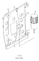
Referring to the drawings and initially to FIGS. 1–3 , a cushion in accordance with the preferred embodiment of the present invention comprises a flexible curved main body 10 having a first end formed with a fixed portion 11 and a second end formed with a movable portion 12, and an elastic mechanism 2 mounted on the main body 10 and biased between the fixed portion 11 and the movable portion 12 of the main body 10.
The elastic mechanism 2 includes a tensile spring 21 having a first end secured on the fixed portion 11 of the main body 10 and a second end secured on the movable portion 12 of the main body 10.
The fixed portion 11 of the main body 10 has a mediate portion formed with a substantially inverted L-shaped support plate 13 mounted on the first end of the tensile spring 21 of the elastic mechanism 2. The support plate 13 of the fixed portion 11 has a distal end formed with a planar support face 130 to support the first end of the tensile spring 21 of the elastic mechanism 2. The support face 130 of the support plate 13 is formed with a through hole 132, and the first end of the tensile spring 21 is provided with a threaded rod 210 extended through the through hole 132 of the support face 130. A nut 211 is screwed onto the threaded rod 210 of the first end of the tensile spring 21 and rested on a side of the support face 130 of the support plate 13.
The movable portion 12 of the main body 10 has a mediate portion formed with a support block 120 mounted on the second end of the tensile spring 21 of the elastic mechanism 2. The support block 120 of the movable portion 12 is formed with a through hole 122, and the second end of the tensile spring 21 is provided with a threaded rod 212 extended through the through hole 122 of the movable portion 12. A nut 213 is screwed onto the threaded rod 212 of the second end of the tensile spring 21 and rested on a side of the movable portion 12.
As shown in FIG. 3 , the fixed portion 11 of the main body 10 is fixed on a backrest 201 of a chair 20, and the movable portion 12 of the main body 10 is pulled by the elastic force of the tensile spring 21 of the elastic mechanism 2, so that the main body 10 is pulled by the tensile spring 21 to have a smaller curvature.
As shown in FIGS. 4 and 5 , when a user's back is rested on the main body 10 of the cushion, the main body 10 is pressed and deformed by the user's weight to form a greater curvature and to pull the movable portion 12 outward, so that the curvature of the main body 10 is changed by the pressure of the user's weight. In such a manner, the tensile spring 21 of the elastic mechanism 2 is stretched by the pulling action of the movable portion 12 of the main body 10 to counteract the user's weight and to mate with variation of the curvature of the main body 10, so that the main body 10 has a greater elastic action, and the curvature of the main body 10 is arbitrarily changed in an automatic manner by the elastic force of the tensile spring 21 of the elastic mechanism 2, so as to fit users of different statures and weights.
Referring to FIGS. 6 and 7 , the elastic mechanism 2 includes a support rod 3 having a first end extended through the support plate 13 of the fixed portion 11 and a second end secured on the movable portion 12 of the main body 10, and a compression spring 22 mounted on the support rod 3 and urged between the support plate 13 of the fixed portion 11 and the first end of the support rod 3. The first end of the support rod 3 is provided with an urging plate 30 rested on a first end of the compression spring 22 which has a second end rested on a side of the support face 130 of the support plate 13. The support rod 3 is slidably mounted in the through hole 132 of the support face 130. The second end of the support rod 3 is formed with an outer thread 32 extended through the through hole 122 of the movable portion 12. A nut 31 is screwed onto the outer thread 32 of the support rod 3 and rested on a side of the movable portion 12.
Referring to FIG. 8 , the movable portion 12 of the main body 10 has a mediate portion formed with a locking slot 17, the support face 130 of the support plate 13 is formed with a mounting hole 134, the elastic mechanism 2 includes a tensile spring 24 having a first end secured on the support plate 13 of the fixed portion 11, and the cushion further comprises a guide tube 4 slidably mounted in the mounting hole 134 of the support plate 13 and having a first end provided with a fixing rod 41 locked in the locking slot 17 of the movable portion 12 and a second end provided with a fixing plate 410 locked on a second end of the tensile spring 24.
Accordingly, the elastic mechanism 2 is stretched by the pulling action of the movable portion 12 of the main body 10 to counteract the user's weight and to mate with variation of the curvature of the main body 10, so that when the main body 10 is pressed and deformed by the user's weight, the main body 10 has a greater elastic action, and the curvature of the main body 10 is arbitrarily changed in an automatic manner by the elastic force of the elastic mechanism 2, so as to fit users of different statures and weights. In addition, the cushion only needs to provide the elastic mechanism 2 to reach the purpose of changing the curvature of the cushion arbitrarily, thereby decreasing costs of fabrication.
Although the invention has been explained in relation to its preferred embodiment(s) as mentioned above, it is to be understood that many other possible modifications and variations can be made without departing from the scope of the present invention. It is, therefore, contemplated that the appended claim or claims will cover such modifications and variations that fall within the true scope of the invention.
Claims (8)
1. A cushion, comprising:
a flexible curved main body having a first end formed with a fixed portion and a second end formed with a movable portion; and
an elastic mechanism mounted on the main body and biased between the fixed portion and the movable portion of the main body; wherein
the elastic mechanism includes a tensile spring having a first end secured on the fixed portion of the main body and a second end secured on the movable portion of the main body;
the fixed portion of the main body is formed with a support plate mounted on the first end of the tensile spring of the elastic mechanism;
the support plate of the fixed portion has a distal end formed with a planar support face to support the first end of the tensile spring of the elastic mechanism;
the support face of the support plate is formed with a through hole, the first end of the tensile spring is provided with a threaded rod extended through the through hole of the support face, and the elastic mechanism further includes a nut screwed onto the threaded rod of the first end of the tensile spring and rested on a side of the support face of the support plate.
2. The cushion in accordance with claim 1 , wherein the support plate of the fixed portion is substantially inverted L-shaped.
3. The cushion in accordance with claim 1 , wherein the fixed portion of the main body is formed with a support plate, and the elastic mechanism includes a support rod having a first end extended through the support plate of the fixed portion and a second end secured on the movable portion of the main body, and a compression spring mounted on the support rod and urged between the support plate of the fixed portion and the first end of the support rod.
4. The cushion in accordance with claim 3 , wherein the support plate of the fixed portion has a distal end formed with a planar support face, and the first end of the support rod is provided with an urging plate rested on a first end of the compression spring which has a second end rested on a side of the support face of the support plate.
5. The cushion in accordance with claim 4 , wherein the support face of the support plate is formed with a through hole, and the support rod is slidably mounted in the through hole of the support face.
6. The cushion in accordance with claim 3 , wherein the movable portion of the main body is formed with a through hole, the second end of the support rod is formed with an outer thread extended through the through hole of the movable portion, and the elastic mechanism further includes a nut screwed onto the outer thread of the support rod and rested on a side of the movable portion.
7. The cushion in accordance with claim 1 , wherein the fixed portion of the main body is formed with a support plate having a distal end formed with a planar support face formed with a mounting hole, the movable portion of the main body is formed with a locking slot, the elastic mechanism includes a tensile spring having a first end secured on the support plate of the fixed portion, and the cushion further comprises a guide tube slidably mounted in the mounting hole of the support plate and having a first end provided with a fixing rod locked in the locking slot of the movable portion and a second end provided with a fixing plate locked on a second end of the tensile spring.
8. A cushion, comprising: a flexible curved main body having a first end formed with a fixed portion and a second end formed with a movable portion; and
an elastic mechanism mounted on the main body and biased between the fixed portion and the movable portion of the main body, wherein
the elastic mechanism includes a tensile spring having a first end secured on the fixed portion of the main body and a second end secured on the movable portion of the main body;
the movable portion of the main body is formed with a support block mounted on the second end of the tensile spring of the elastic mechanism;
the support block of the movable portion is formed with a through hole, the second end of the tensile spring is provided with a threaded rod extended through the through hole of the movable portion, and the elastic mechanism further includes a nut screwed onto the threaded rod of the second end of the tensile spring and rested on a side of the movable portion.
Priority Applications (1)
| Application Number | Priority Date | Filing Date | Title |
|---|---|---|---|
| US10/871,779 US6981742B1 (en) | 2004-06-19 | 2004-06-19 | Cushion for backrest of chair |
Applications Claiming Priority (1)
| Application Number | Priority Date | Filing Date | Title |
|---|---|---|---|
| US10/871,779 US6981742B1 (en) | 2004-06-19 | 2004-06-19 | Cushion for backrest of chair |
Publications (2)
| Publication Number | Publication Date |
|---|---|
| US20050280298A1 US20050280298A1 (en) | 2005-12-22 |
| US6981742B1 true US6981742B1 (en) | 2006-01-03 |
Family
ID=35479889
Family Applications (1)
| Application Number | Title | Priority Date | Filing Date |
|---|---|---|---|
| US10/871,779 Active US6981742B1 (en) | 2004-06-19 | 2004-06-19 | Cushion for backrest of chair |
Country Status (1)
| Country | Link |
|---|---|
| US (1) | US6981742B1 (en) |
Cited By (3)
| Publication number | Priority date | Publication date | Assignee | Title |
|---|---|---|---|---|
| US20060255646A1 (en) * | 2005-04-08 | 2006-11-16 | Banyan Licensing Lc | Portable support cushion |
| US20070140851A1 (en) * | 2005-12-21 | 2007-06-21 | General Electric Company | Method and apparatus for cooling gas turbine rotor blades |
| US20070189898A1 (en) * | 2006-02-16 | 2007-08-16 | General Electric Company | Method and apparatus for cooling gas turbine rotor blades |
Families Citing this family (4)
| Publication number | Priority date | Publication date | Assignee | Title |
|---|---|---|---|---|
| US7918506B2 (en) * | 2009-02-06 | 2011-04-05 | Chern Shing Top Co., Ltd. | Padding structure for a chair |
| US10433643B2 (en) * | 2017-05-12 | 2019-10-08 | Rocking Inc. | Portable rebounding device |
| US10561247B2 (en) * | 2018-05-31 | 2020-02-18 | Chem Shing Top Co., Ltd. | Chair back structure |
| KR102494887B1 (en) | 2021-03-22 | 2023-02-06 | 주식회사 디에스시동탄 | Actuator for recliner |
Citations (9)
| Publication number | Priority date | Publication date | Assignee | Title |
|---|---|---|---|---|
| US5217278A (en) * | 1991-03-13 | 1993-06-08 | Findlay Industries, Inc. | Mechanism for providing adjustable lumbar support in a seat |
| US5335965A (en) * | 1990-03-09 | 1994-08-09 | Lorenza Sessini | Cushion for anatomical support, especially for the lumbar and cervical regions, to fit onto seat backs |
| US5567011A (en) * | 1990-03-09 | 1996-10-22 | Sessini; Lorenza | Cushion for anatomical support, especially for the lumbar and cervical regions, to fit onto seat backs |
| US6030041A (en) * | 1999-03-02 | 2000-02-29 | Hsiao; Jin-Long | Back pad adjusting structure |
| US6227617B1 (en) * | 1997-04-10 | 2001-05-08 | Megaplast S.A. | Back support for seat-backs, in particular for motor vehicle seats |
| US20020113472A1 (en) * | 2001-02-21 | 2002-08-22 | Horia Blendea | Powered actuator for lumbar unit |
| US6758522B2 (en) * | 2001-03-29 | 2004-07-06 | L&P Property Management Company | Apparatus and method for varying coefficients of friction in a variable apex back support |
| US6779844B2 (en) * | 2001-12-14 | 2004-08-24 | L&P Propety Maqnagement Company | Arching lumbar support with weight distribution surface |
| US6805405B2 (en) * | 2001-03-19 | 2004-10-19 | Sung Yong Co., Ltd. | Chair equipped with lumbar support unit |
-
2004
- 2004-06-19 US US10/871,779 patent/US6981742B1/en active Active
Patent Citations (9)
| Publication number | Priority date | Publication date | Assignee | Title |
|---|---|---|---|---|
| US5335965A (en) * | 1990-03-09 | 1994-08-09 | Lorenza Sessini | Cushion for anatomical support, especially for the lumbar and cervical regions, to fit onto seat backs |
| US5567011A (en) * | 1990-03-09 | 1996-10-22 | Sessini; Lorenza | Cushion for anatomical support, especially for the lumbar and cervical regions, to fit onto seat backs |
| US5217278A (en) * | 1991-03-13 | 1993-06-08 | Findlay Industries, Inc. | Mechanism for providing adjustable lumbar support in a seat |
| US6227617B1 (en) * | 1997-04-10 | 2001-05-08 | Megaplast S.A. | Back support for seat-backs, in particular for motor vehicle seats |
| US6030041A (en) * | 1999-03-02 | 2000-02-29 | Hsiao; Jin-Long | Back pad adjusting structure |
| US20020113472A1 (en) * | 2001-02-21 | 2002-08-22 | Horia Blendea | Powered actuator for lumbar unit |
| US6805405B2 (en) * | 2001-03-19 | 2004-10-19 | Sung Yong Co., Ltd. | Chair equipped with lumbar support unit |
| US6758522B2 (en) * | 2001-03-29 | 2004-07-06 | L&P Property Management Company | Apparatus and method for varying coefficients of friction in a variable apex back support |
| US6779844B2 (en) * | 2001-12-14 | 2004-08-24 | L&P Propety Maqnagement Company | Arching lumbar support with weight distribution surface |
Cited By (5)
| Publication number | Priority date | Publication date | Assignee | Title |
|---|---|---|---|---|
| US20060255646A1 (en) * | 2005-04-08 | 2006-11-16 | Banyan Licensing Lc | Portable support cushion |
| US20070140851A1 (en) * | 2005-12-21 | 2007-06-21 | General Electric Company | Method and apparatus for cooling gas turbine rotor blades |
| US7431562B2 (en) | 2005-12-21 | 2008-10-07 | General Electric Company | Method and apparatus for cooling gas turbine rotor blades |
| US20070189898A1 (en) * | 2006-02-16 | 2007-08-16 | General Electric Company | Method and apparatus for cooling gas turbine rotor blades |
| US7431561B2 (en) | 2006-02-16 | 2008-10-07 | General Electric Company | Method and apparatus for cooling gas turbine rotor blades |
Also Published As
| Publication number | Publication date |
|---|---|
| US20050280298A1 (en) | 2005-12-22 |
Similar Documents
| Publication | Publication Date | Title |
|---|---|---|
| US6843530B1 (en) | Multi-stage backrest assembly | |
| US6059362A (en) | Adjustable waist support device for chairs | |
| US7979933B2 (en) | Headrest assembly with improved flexibility for a massage device | |
| US6957867B1 (en) | Height-adjustable armrest | |
| JP3616100B2 (en) | Back support with variable vertex | |
| JP5519652B2 (en) | Armrest device | |
| US6398309B1 (en) | Level-adjustable and swivelable armrest assembly | |
| US6030041A (en) | Back pad adjusting structure | |
| US8449485B2 (en) | Cervical collar with cable reel adjustment system | |
| US6981742B1 (en) | Cushion for backrest of chair | |
| US20080156962A1 (en) | Telescopic adjustable positioning device | |
| US6616236B1 (en) | Adjustable headrest device | |
| US20070151208A1 (en) | Stretch film dispenser | |
| US6923416B1 (en) | Adjustable device with a musical keyboard stand | |
| US10376071B2 (en) | Leaning chair | |
| US7306288B2 (en) | Adjustable armrest assembly | |
| US20040066075A1 (en) | Structure for adjusting backrest for collapsible chairs | |
| US20100117423A1 (en) | Positioning Device For Chair | |
| US7367628B1 (en) | Armrest that will not produce noise during adjustment | |
| US20050184200A1 (en) | Lordosis support | |
| US20070046079A1 (en) | Integrally formed table and chair assembly | |
| US8556345B2 (en) | Chair having angle and tension adjusting functions | |
| US20110133048A1 (en) | Seat adjuster for sports equipment | |
| US20030052474A1 (en) | Stroller seat back leaning angle adjusting device | |
| GB2593953A (en) | Armrest structure with adjustable lifting function |
Legal Events
| Date | Code | Title | Description |
|---|---|---|---|
| AS | Assignment |
Owner name: CHEN HSING ENTERPRISE CO., LTD., TAIWAN Free format text: ASSIGNMENT OF ASSIGNORS INTEREST;ASSIGNOR:HSIAO, HIN-LONG;REEL/FRAME:015498/0718 Effective date: 20040611 |
|
| STCF | Information on status: patent grant |
Free format text: PATENTED CASE |
|
| FPAY | Fee payment |
Year of fee payment: 4 |
|
| FPAY | Fee payment |
Year of fee payment: 8 |
|
| FPAY | Fee payment |
Year of fee payment: 12 |