US6993427B2 - Combustion state estimating apparatus for internal combustion engine - Google Patents
Combustion state estimating apparatus for internal combustion engine Download PDFInfo
- Publication number
- US6993427B2 US6993427B2 US10/634,812 US63481203A US6993427B2 US 6993427 B2 US6993427 B2 US 6993427B2 US 63481203 A US63481203 A US 63481203A US 6993427 B2 US6993427 B2 US 6993427B2
- Authority
- US
- United States
- Prior art keywords
- torque
- crank angle
- friction torque
- state
- combustion
- Prior art date
- Legal status (The legal status is an assumption and is not a legal conclusion. Google has not performed a legal analysis and makes no representation as to the accuracy of the status listed.)
- Expired - Fee Related, expires
Links
Images


Classifications
-
- F—MECHANICAL ENGINEERING; LIGHTING; HEATING; WEAPONS; BLASTING
- F02—COMBUSTION ENGINES; HOT-GAS OR COMBUSTION-PRODUCT ENGINE PLANTS
- F02D—CONTROLLING COMBUSTION ENGINES
- F02D41/00—Electrical control of supply of combustible mixture or its constituents
- F02D41/02—Circuit arrangements for generating control signals
- F02D41/14—Introducing closed-loop corrections
- F02D41/1497—With detection of the mechanical response of the engine
- F02D41/1498—With detection of the mechanical response of the engine measuring engine roughness
-
- F—MECHANICAL ENGINEERING; LIGHTING; HEATING; WEAPONS; BLASTING
- F02—COMBUSTION ENGINES; HOT-GAS OR COMBUSTION-PRODUCT ENGINE PLANTS
- F02D—CONTROLLING COMBUSTION ENGINES
- F02D2200/00—Input parameters for engine control
- F02D2200/02—Input parameters for engine control the parameters being related to the engine
- F02D2200/10—Parameters related to the engine output, e.g. engine torque or engine speed
- F02D2200/1002—Output torque
- F02D2200/1004—Estimation of the output torque
-
- F—MECHANICAL ENGINEERING; LIGHTING; HEATING; WEAPONS; BLASTING
- F02—COMBUSTION ENGINES; HOT-GAS OR COMBUSTION-PRODUCT ENGINE PLANTS
- F02D—CONTROLLING COMBUSTION ENGINES
- F02D2200/00—Input parameters for engine control
- F02D2200/02—Input parameters for engine control the parameters being related to the engine
- F02D2200/10—Parameters related to the engine output, e.g. engine torque or engine speed
- F02D2200/1006—Engine torque losses, e.g. friction or pumping losses or losses caused by external loads of accessories
-
- F—MECHANICAL ENGINEERING; LIGHTING; HEATING; WEAPONS; BLASTING
- F02—COMBUSTION ENGINES; HOT-GAS OR COMBUSTION-PRODUCT ENGINE PLANTS
- F02D—CONTROLLING COMBUSTION ENGINES
- F02D2200/00—Input parameters for engine control
- F02D2200/02—Input parameters for engine control the parameters being related to the engine
- F02D2200/10—Parameters related to the engine output, e.g. engine torque or engine speed
- F02D2200/1012—Engine speed gradient
-
- F—MECHANICAL ENGINEERING; LIGHTING; HEATING; WEAPONS; BLASTING
- F02—COMBUSTION ENGINES; HOT-GAS OR COMBUSTION-PRODUCT ENGINE PLANTS
- F02D—CONTROLLING COMBUSTION ENGINES
- F02D2200/00—Input parameters for engine control
- F02D2200/02—Input parameters for engine control the parameters being related to the engine
- F02D2200/10—Parameters related to the engine output, e.g. engine torque or engine speed
- F02D2200/1015—Engines misfires
-
- F—MECHANICAL ENGINEERING; LIGHTING; HEATING; WEAPONS; BLASTING
- F02—COMBUSTION ENGINES; HOT-GAS OR COMBUSTION-PRODUCT ENGINE PLANTS
- F02D—CONTROLLING COMBUSTION ENGINES
- F02D41/00—Electrical control of supply of combustible mixture or its constituents
- F02D41/0097—Electrical control of supply of combustible mixture or its constituents using means for generating speed signals
-
- F—MECHANICAL ENGINEERING; LIGHTING; HEATING; WEAPONS; BLASTING
- F02—COMBUSTION ENGINES; HOT-GAS OR COMBUSTION-PRODUCT ENGINE PLANTS
- F02D—CONTROLLING COMBUSTION ENGINES
- F02D41/00—Electrical control of supply of combustible mixture or its constituents
- F02D41/02—Circuit arrangements for generating control signals
- F02D41/04—Introducing corrections for particular operating conditions
- F02D41/042—Introducing corrections for particular operating conditions for stopping the engine
-
- F—MECHANICAL ENGINEERING; LIGHTING; HEATING; WEAPONS; BLASTING
- F02—COMBUSTION ENGINES; HOT-GAS OR COMBUSTION-PRODUCT ENGINE PLANTS
- F02D—CONTROLLING COMBUSTION ENGINES
- F02D41/00—Electrical control of supply of combustible mixture or its constituents
- F02D41/02—Circuit arrangements for generating control signals
- F02D41/04—Introducing corrections for particular operating conditions
- F02D41/06—Introducing corrections for particular operating conditions for engine starting or warming up
- F02D41/062—Introducing corrections for particular operating conditions for engine starting or warming up for starting
Definitions
- the invention relates to a combustion state estimating apparatus for an internal combustion engine, and is applied to an apparatus that estimates the state of combustion from a parameter regarding rotation of a crankshaft.
- Japanese Patent Application Laid-open No. 9-303243 teaches a method in which an angular acceleration of an engine is detected with reference to two predetermined points in the combustion stroke, and a parameter of the engine is adjusted so as to optimize the state of combustion on the basis of the amount of deviation between the all-cylinders average value of angular acceleration and an individual-cylinder average value thereof.
- the angular acceleration detected outside the engine includes information resulting from the state of combustion, and other various kinds of information, such as the inertia mass of driving portions, the friction thereof, etc. Therefore, the detected angular acceleration does not always agree with the state of combustion. Hence, in some cases, the state of combustion estimated from the angular acceleration includes an error.
- the angular acceleration is evaluated in a relative fashion on the basis of the amount of the deviation between the all-cylinders average value of angular acceleration and the individual-cylinder average value of angular acceleration.
- the process for calculating the average values and the amount of deviation is complicated.
- the measurement of the combustion state through such a relative evaluation is possible only during steady operation of the engine. Therefore, a complicated and cumbersome process needs to be performed; for example, the threshold value used for determination is changed every time the operational condition changes. Therefore, according to the aforementioned conventional method, it is impossible to provide an estimation of the state of combustion corresponding to various operational conditions of the engine, and it is difficult to estimate the state of combustion at an arbitrary timing assuming a real operation of the vehicle.
- the Japanese Patent Application Laid-open No. 11-294213 teaches calculation of the friction torque using a map of the engine rotation speed and the cooling water temperature.
- the invention has been accomplished in view of the aforementioned problems.
- the invention provides a combustion state estimating apparatus for an internal combustion engine which is capable of estimating the state of combustion of the internal combustion engine with high precision by minimizing the effect of factors or information other than the information related to the state of combustion.
- the invention provides, as an embodiment, a combustion state estimating apparatus for estimating a state of combustion in an internal combustion engine.
- the apparatus includes an angular acceleration calculator that calculates a crank angle acceleration, and a combustion state estimator that estimates the state of combustion in the internal combustion engine based on the crank angle acceleration in a crank angle interval in which an average value of inertia torque caused by a reciprocating inertia mass of the internal combustion engine is substantially zero.
- the combustion state estimating apparatus for an internal combustion engine constructed as described above, the state of combustion is estimated on the basis of the angular acceleration in an interval in which the average value of inertia torque caused by the reciprocating inertia mass of the internal combustion engine is substantially zero. Therefore, the combustion state estimating apparatus excludes the effect that the inertia torque caused by the reciprocating inertia mass has on the angular acceleration. Hence, the apparatus allows precise estimation of the state of combustion based on the angular acceleration.
- FIG. 1 is a diagram illustrating the structure of a combustion state estimating apparatus of an internal combustion engine according to an embodiment of the invention, and portions around the apparatus;
- FIG. 2 is a characteristic diagram indicating relationships between the crank angle and the indicated torque, the torque caused by the in-cylinder gas pressure, and the inertia torque caused by the reciprocating inertia mass;
- FIG. 3 is a schematic diagram illustrating a method for determining the angular acceleration of a crankshaft
- FIG. 4 is a schematic diagram illustrating a map that indicates relationships among the friction torque, the engine rotation speed, and the cooling water temperature
- FIG. 5 is a flowchart illustrating the procedure of a process performed by the combustion state estimating apparatus
- FIG. 6 is a schematic diagram illustrating a relationship between the indicated torque T i (k) and the strokes of each cylinder;
- FIG. 7 is a characteristic diagram indicating results of estimation of the indicated torque
- FIG. 8A is a characteristic diagram indicating the results indicated in FIG. 7 with regard to the first cylinder
- FIG. 8B is a characteristic diagram indicating the results indicated in FIG. 7 with regard to the third cylinder
- FIG. 8C is a characteristic diagram indicating the results indicated in FIG. 7 with regard to the fourth cylinder.
- FIG. 8D is a characteristic diagram indicating the results indicated in FIG. 7 with regard to the second cylinder
- FIG. 9A is a characteristic diagram indicating the torque characteristic of a single-cylinder engine
- FIG. 9B is a characteristic diagram indicating the torque characteristics of a six-cylinder engine.
- FIG. 10 is a flowchart illustrating the procedure of a process according to a first method for friction torque correction
- FIG. 11 is a schematic diagram illustrating a method for correction of the friction torque T f ;
- FIG. 12 is a schematic diagram illustrating another method for correction of the friction torque T f ;
- FIG. 13 is a flowchart illustrating the procedure of a process according to a second method for friction torque correction
- FIG. 14 is a flowchart illustrating the procedure of a process according to a third method for friction torque correction
- FIG. 15A is a schematic diagram for explanation of the pumping loss, illustrating a case where the throttle valve 22 is fully open
- FIG. 15B is a schematic diagram for explanation of the pumping loss, illustrating a case where the throttle valve 22 is completely closed;
- FIG. 16A is a characteristic diagram indicating the torque produced in each cylinder of a four-cylinder engine, illustrating a case where the throttle valve is fully open;
- FIG. 16B is a characteristic diagram indicating the torque produced in each cylinder of a four-cylinder engine, illustrating a case where the throttle valve is completely closed;
- FIG. 17 is a flowchart illustrating the procedure of a process according to a fourth method for friction torque correction.
- FIG. 18 is a flowchart illustrating the procedure of a process according to a fifth method for friction torque correction.
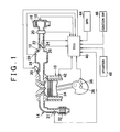
- FIG. 1 is a diagram illustrating the structure of a combustion state estimating apparatus of an internal combustion engine according to Embodiment 1 of the invention and portions around the apparatus.
- An intake passageway 12 and an exhaust passageway 14 are connected to an internal combustion engine 10 .
- An air filter 16 is provided in an upstream-side end portion of the intake passageway 12 .
- An intake temperature sensor 18 for detecting the intake air temperature THA i.e., the external air temperature
- the exhaust passageway 14 is provided with an exhaust emission control catalyst 32 , and an exhaust pressure sensor 31 for detecting the exhaust pressure.
- An air flow meter 20 is disposed downstream of the air filter 16 .
- a throttle valve 22 is provided downstream of the air flow meter 20 .
- the throttle valve 22 is formed by, for example, an electronic throttle valve.
- the degree of opening of the throttle valve 22 is controlled on the basis of a command from an ECU 40 .
- Disposed near the throttle valve 22 are a throttle sensor 24 for detecting the degree of throttle opening TA, and an idle switch 26 that turns on when the throttle valve 22 is completely closed.
- a surge tank 28 is provided downstream of the throttle valve 22 .
- An intake pipe pressure sensor 29 for detecting the pressure in the intake passageway 12 (intake pipe pressure) is provided near the surge tank 28 .
- a fuel injection valve 30 for injecting fuel into an intake port of the internal combustion engine 10 is disposed downstream of the surge tank 28 .
- Each cylinder of the internal combustion engine 10 has a piston 34 .
- the piston 34 is connected to a crankshaft 36 that is rotated by the reciprocating movements thereof.
- a vehicle drive system and accessories (such as an air-conditioner compressor, an alternator, a torque converter, a power steering pump, etc.) are driven by the rotating torque of the crankshaft 36 .
- a crank angle sensor 38 for detecting the rotational angle of the crankshaft 36 is disposed near the crankshaft 36 .
- a cylinder block of the engine 10 is provided with a water temperature sensor 42 for detecting the cooling water temperature.
- the combustion state estimating apparatus of the embodiment has an ECU (electronic control unit) 40 .
- the ECU 40 is connected to the aforementioned various sensors and the fuel injection valve 30 , and is also connected to a vehicle speed sensor 44 for detecting the vehicle speed SPD, etc.
- An ignition switch 46 for switching the state of the engine between operation and stop, and a starter 48 for rotating the crankshaft 36 by performing the cranking at the time of startup the engine are also connected to the ECU 40 .
- the ignition switch 46 is changed from an off-state to an on-state, the cranking via the starter 48 is performed, and fuel is injected from the fuel injection valve 30 , and is ignited, so as to start up the engine.
- the ignition switch 46 is changed from the on-state to the off-state, the fuel injection from the fuel injection valve 30 and the ignition are stopped, so that the engine stops.
- the indicated torque T i is the torque generated on the crankshaft 36 by combustion in the engine 10 .
- the right-hand side of the equation (2) expresses torques that form the indicated torque T i .
- the right-hand side of the equation (1) expresses torques that consume the indicated torque T i .
- J represents the inertia moment of the driving members driven by the combustion of air-fuel mixture and the like
- d ⁇ /dt represents the angular acceleration of the crankshaft 36
- T f represents the friction torque of the driving portion
- the T i represents the load torque from the road surface during the run of the vehicle.
- the friction torque T f is the torque caused by mechanical frictions of various connecting portions, such as the friction between the piston 34 and a cylinder inner wall, and the like, and includes the torque caused by mechanical frictions of accessories.
- the load torque T l is the torque caused by external disturbance, such as the state of the road during the run of the vehicle, and the like.
- T gas represents the torque caused by the gas pressure in the cylinder
- T inertia represents the inertia torque caused by the reciprocating inertia mass of the piston 34 , and the like.
- the torque T gas caused by the in-cylinder gas pressure is generated by the combustion of air-fuel mixture in the cylinder. In order to accurately estimate the state of combustion, it is necessary to determine the torque T gas caused by the in-cylinder gas pressure.
- the indicated torque T j can be determined as the sum of the dynamic lost torque J ⁇ d ⁇ /dt attributed to the angular acceleration, the friction torque T f , and the load torque T 1 .
- the indicated torque T i is not equal to the torque T gas caused by the in-cylinder gas pressure as indicated by the equation (2), it is impossible to precisely estimate the state of combustion from the indicated torque T i .
- FIG. 2 is a characteristic diagram indicating relationships between the various torques and the crank angle.
- the vertical axis indicates the magnitude of torque
- the horizontal axis indicates the crank angle.
- a one-dot chain line indicates the indicated torque T i
- a solid line indicates the torque T gas caused by the in-cylinder gas pressure
- a broken line indicates the inertia torque T inertia caused by the reciprocating inertia mass.
- FIG. 2 indicates characteristics in the case of a four-cylinder engine. In FIG.
- TDC and BDC indicate the crank angle (0°) at which the piston 34 of one of the four cylinders is at the top dead center (TDC) and the crank angle (180°) at which the piston 34 of the same cylinder is at the bottom dead center (BDC).
- TDC top dead center
- BDC bottom dead center
- the torque T gas caused by the in-cylinder gas pressure sharply increases and decreases between the TDC and the BDC.
- the sharp increase in the torque T gas is caused by the explosion of a mixture in the combustion chamber during the explosion stroke. After the explosion, the torque T gas decreases, and assumes negative values due to the influences of the cylinders undergoing the compression stroke or the exhaust stroke. Then, when the crank angle reaches the BDC, the change in the capacity of the cylinder becomes zero, so that the torque T gas assumes the value of 0.
- the inertia torque T inertia caused by the reciprocating inertia mass is an inertia torque generated by the inertia mass of the reciprocating members, such as the pistons 34 and the like, and is substantially irrelevant to the torque T gas caused by the in-cylinder gas pressure, or is irrelevant thereto so that the effect of the torque T gas on the inertia torque T inertia is ignorable.
- the reciprocating members undergo acceleration-deceleration cycles, and the inertia torque T inertia always occurs as long as the crankshaft 36 rotates, even if the angular speed is constant. As indicated by the broken line in FIG.
- T inertia 0
- the reciprocating members start moving from the stopped state. Due to the inertia of the reciprocating members, the torque T inertia increases in the negative direction.
- the crank angle reaches the vicinity of 90°
- the reciprocating members are moving at a predetermined speed, and therefore the crankshaft 36 continues rotating due to the inertia of the members. Therefore, the torque T inertia changes from the negative side to the opposite side between the TDC and the BDC. After that, when the crank angle reaches the BDC, the reciprocating members stop, and the inertia torque T inertia becomes equal to zero.
- the indicated torque T i is the sum of the torque T gas caused by the in-cylinder gas pressure and the inertia torque T inertia caused by the reciprocating inertia mass. Therefore, as indicated by the one-dot chain line in FIG. 2 , the indicated torque Ti exhibits a complicated behavior in which, between the TDC and the BDC, the indicated torque Ti increases due to increases in the torque Tgas caused by the explosion of mixture, and temporarily decreases, and then increases again due to the inertia torque T inertia .
- the average value of each torque in the interval of the TDC to the BDC is determined, the average value of the indicated torque T j becomes equal to the average value of the torque T gas caused by the in-cylinder gas pressure in the equation (2) since the average of the inertia torque T inertia in the same interval is “0”. Therefore, the state of combustion can be precisely estimated on the basis of the indicated torque T j .
- FIG. 3 is a schematic diagram illustrating a method for determining the angular acceleration of the crankshaft 36 . As indicated in FIG. 3 , a crank angle signal via the crank angle sensor 38 is detected at every rotational angle of 10° of the crankshaft 36 in this embodiment.
- the combustion state estimating apparatus of the embodiment calculates the angular acceleration-caused dynamic lost torque T ac as an average value in the interval of the TDC to the BDC. To this end, the apparatus of the embodiment determines angular speeds ⁇ 0 (k), ⁇ 0 (k+1) at the two points in crank angle, that is, the TDC and the BDC, and also determines the time ⁇ t(k) of the rotation of the crankshaft 36 from the TDC to the BDC.
- the average value of angular acceleration and the inertia moment J are multiplied according to the right-hand side of the equation (1). In this manner, an average value of the dynamic lost torque J ⁇ (d ⁇ /dt) during the rotation of the crankshaft 36 from the TDC to the BDC can be calculated. It is to be noted herein that the inertia moment J of the driving portion is determined beforehand from the inertia mass of the driving component parts.
- FIG. 4 is a map indicating relationships among the friction torque T f , the engine rotation speed (Ne) of the internal combustion engine 10 , and the cooling water temperature (thw).
- the friction torque T f , the engine rotation speed (Ne) and the cooling water temperature (thw) are the average values for the duration of rotation of the crankshaft 36 from the TDC to the BDC.
- the friction torque T f is the torque caused by the mechanical friction of the connecting portions, such as friction between the piston 34 and the cylinder inner wall, and includes the torque caused by the mechanical friction of accessories.
- the cooling water temperature becomes higher in the order of thw 1 ⁇ thw 2 ⁇ thw 3 .
- the friction torque T f tends to increase with increases in the engine rotation speed (Ne), and to increase with decreases in the cooling water temperature (thw).
- the map shown in FIG. 4 is prepared beforehand by measuring friction torques T f generated during rotation of the crankshaft 36 from the TDC to the BDC with varied values of the engine rotation speed (Ne) and the cooling water temperature (thw), and determining average values of the measured friction torques T f .
- an average value of the friction torque T f corresponding to the average value of the cooling water temperature (thw) and the average value of the engine rotation speed in the interval of the TDC to the BDC is determined from the map shown in FIG. 4 .
- the cooling water temperature is detected via the water temperature sensor 42
- the engine rotation speed is detected via the crank angle sensor 38 .
- the interval from the TDC (top dead center) to the BDC (bottom dead center), or from the BDC to the TDC is an interval in which the average value of the inertia torque T inertia caused by the reciprocating inertia mass is “0”, and the average values of the friction torque T f in such intervals are substantially uniform.
- an average value of the friction torque T f is determined for every interval (TDC ⁇ BDC) in which the average value of the inertia torque T inertia caused by the reciprocating inertia mass is “0”, it becomes possible to precisely detect a relationship among the engine rotation speed (Ne), the cooling water temperature (thw), and the friction torque T f , which exhibits complicated transient behaviors.
- the handling of the friction torque T f as the average value for every interval will allow accurate map formation as indicated in FIG. 4 .
- the map of FIG. 4 has been prepared by varying the engine rotation speed (Ne) and the cooling water temperature (thw) as parameters, and measuring the friction torque T f that occurs during rotation of the crankshaft 36 from the TDC to the BDC, and calculating an average value thereof.
- the values of the engine rotation speed (Ne) and the cooling water temperature (thw) in FIG. 4 are average values thereof for the TDC-BDC interval, similar to the values of the friction torque T f .
- the interval that allows stable determination or computation of the friction torque T f is an interval in which the average value of the inertia torque caused by the reciprocating inertia mass of the engine, for example, the pistons 34 and the like, is “0”.
- the torque computation interval is an interval of crank angle of 18° between the TDC and the BDC, assuming that the engine 10 is a four-cylinder engine.
- the torque computation interval may be an interval where the average value of the inertia torque caused by the reciprocating inertia mass becomes “0”.
- the ECU 40 stores a map as indicated in FIG. 4 in a memory.
- the ECU 40 estimates a friction torque T f through the use of the map, and uses the estimated value for calculation of the indicated torque, and the like.
- an average value of the friction torque T f in the TDC-BDC interval is determined on the basis of the TDC-BDC interval average value of the cooling water temperature and the TDC-BDC interval average value of the engine rotation speed, with reference to the map of FIG. 4 .
- the cooling water temperature and the engine rotation speed are detected via the water temperature sensor 42 and the crank angle sensor 38 , respectively.
- the friction torque T f in the TDC-BDC interval can be accurately estimated, and therefore, the indicated torque can be accurately determined on the basis of the friction torque T f , as described below.
- the friction torque T f includes the torque caused by the friction of accessories, as mentioned above.
- the value of torque caused by the friction of accessories changes depending on whether the accessories are in operation.
- an air-conditioner compressor that is, one of the accessories, receives rotations transmitted from the engine via a belt or the like, so that a torque is caused by friction even if the air-conditioner is not in operation.
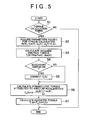
- step S 1 it is determined whether the crank angle has reached a torque calculation timing. More specifically, it is determined whether the present crank angle is in the state where the crank angle is equal to or greater than TDC+10° or the state where the crank angle is equal to or greater than BDC+10°. If the present crank angle corresponds to the torque calculation timing, the process proceeds to step S 2 . If the present crank angle does not correspond to the torque calculation timing, the process ends.
- step S 2 parameters needed for torque calculation are acquired.
- the parameters acquired include the engine rotation speed (Ne(k)), the cooling water temperature (thw(k)), the angular speeds ( ⁇ 0 (k), ⁇ 0 (k+1)), the time ( ⁇ t), etc.
- a friction torque T f (k) is calculated.
- the friction torque T f (k) is a function of the engine rotation speed (Ne(k)) and the cooling water temperature (thw(k)), and an average value of the friction torque T f in the interval of the TDC to the BDC is determined from the map of FIG. 4 .
- step S 4 it is determined whether the switch of an accessory is on. If the switch is on, the process proceeds to step S 5 , in which the friction torque T f (k) determined in step S 3 is corrected. Specifically, the friction torque T f (k) is corrected by, for example, a method of multiplying T f (k) by a predetermined correction factor, or a method of adding a predetermined correction value to T f (k), etc. If it is determined that the switch of an accessory is off, the process proceeds to step S 6 .
- step S 6 a dynamic lost torque T ac (k) attributed to angular acceleration is calculated.
- T ac (k) J ⁇ ( ⁇ 0 (K+1) ⁇ 0 (k))/ ⁇ t, the average value T ac (k) of dynamic lost torque in the interval of the TDC to the BDC is determined.
- step S 7 the indicated torque T j (k) calculated.
- the thus-determined indicated torque T i (k) is an average value obtained in the interval of the TDC to the BDC.
- the indicated torque T i (k ⁇ 2) corresponds to the explosion in the cylinder # 4
- the indicated torque T i (k ⁇ 1) corresponds to the explosion in the cylinder # 2
- the indicated torque T i (k+1) corresponds to the explosion in the cylinder # 3
- the indicated torque T i (k+2) corresponds to the explosion in the cylinder # 4 .
- the indicated torque T i (k)
- the cylinder # 1 undergoes the explosion stroke
- the cylinder # 3 undergoes the compression stroke
- the cylinder # 4 undergoes the intake stroke
- the cylinder # 2 undergoes the exhaust stroke. Since the torques produced by the compression, intake and exhaust strokes are very small compared with the torque produced by the in-cylinder gas pressure generated in the explosion stroke, the indicated torque T i can be considered equal to the torque T gas caused by the in-cylinder gas pressure generated by explosion in the cylinder # 1 .
- the torque T gas produced by the in-cylinder gas pressure caused by explosion in each cylinder can be calculated in the order of # 4 , # 2 , # 1 , # 3 , # 4 . Therefore, the state of combustion in each cylinder can be estimated.
- This characteristic diagram is obtained by plotting indicated torque T i (k) estimated for every explosion stroke of the cylinders # 1 to # 4 . Since the combustion state estimating apparatus of the embodiment is able to exclude the effect of the inertia torque T inertia caused by the reciprocating inertia mass and to highly precisely determine the friction torque T f with reference to a map, the torque T gas generated by the in-cylinder gas pressure can be accurately estimated in absolute value.
- the indicated torque T i (k) varies to some degree during a period of about 30 strokes immediately following the startup, and therefore it can be determined that the state of combustion is not good during that period.
- FIGS. 8A to 8D are characteristic diagrams indicating the results indicated in FIG. 7 separately for the individual cylinders.
- the presentation of the indicated torque T i for each cylinder in this manner makes it possible to estimate the state of combustion in each cylinder.
- the cylinder # 4 does not produce the indicated torque T i immediately after the startup of the engine. Therefore, it can be instantly determined that the state of combustion in the cylinder # 4 is not good.
- the dynamic lost torque T ac due to angular acceleration is determined from the angular speeds at the TDC and the BDC, it is also possible to divide the interval of the TDC to the BDC into a plurality of small intervals and determine a dynamic lost torque attributed to angular acceleration for each of the divided intervals, and average the dynamic lost torques so as to determine a lost torque T ac for every crank angle of 180°.
- the TDC-to-BDC crank angle interval is equally divided into six intervals of 30°, and a dynamic lost torque is determined for every interval of 30° and the determined dynamic lost torques are averaged so as to determine an average value of the dynamic lost torque T ac for the interval of the TDC to the BDC.
- This method increases the number of points of detection of crank angle speed so as to minimize the error in crank angle detection.
- the interval in which the average value of the inertia torque T inertia caused by the reciprocating inertia mass is “0” is an interval of 180°
- the interval that causes the average value of T inertia to be “0” may be set as a broader interval.
- the minimum interval in which the average value of the inertia torque T inertia caused by the reciprocating inertia mass is “0” is an interval of 180°, and therefore, the interval in which the average value of the inertia torque T inertia is “0” may be set at any multiple of 180°. If a low frequency of estimation of the indicated torque Ti is acceptable, for example, if the estimated torque is used for a torque control, a broader angle interval of, for example, 360°, 720° or the like, may be set.
- FIGS. 9A and 9B are torque characteristic diagrams of internal combustion engines other than the four-cylinder engines, each indicating relationships between the various torques in the equation (2) and the crank angle similarly to FIG. 4 .
- FIG. 9A indicates the torque characteristics of a single-cylinder engine
- FIG. 9B indicates the torque characteristics of a six-cylinder engine.
- the single-cylinder engine undergoes the explosion stroke in every crank angle of 720°, and the torque T gas caused by the in-cylinder gas pressure exhibits a rise and a fall for every event of explosion.
- the average value of the torque T inertia (dotted line) caused by the reciprocating inertia mass in an interval of 360° to 540° in crank angle is “0”. Therefore, if an angular acceleration and an indicated torque are determined for every crank angle interval of 360° to 540°, the state of combustion can be precisely estimated.
- the range of angle obtained by the calculation of (720°/the number of cylinders) may be set as a minimum unit of the interval in which the average value of the torque T inertia is “0”.
- the average values of the crank angle acceleration, the lost torque and the friction torque are calculated in the interval where the average value of the inertia torque T inertia caused by the reciprocating inertia mass is “0”, it is also possible to calculate values other than the average values, for example, an integrated value of torque, and the like, in that interval. Since the effect of the torque T inertia is excluded from the interval, this interval allows precise estimation of the state of combustion even if parameters, for example, the integrated value or the like, are used.
- the load torque T l is determined on the basis of information from a slope sensor or the like, and is used to estimate the indicated torque T i , it becomes possible to estimate the state of combustion over the entire region of operation while the vehicle is running. Therefore, even in the case of a cold hesitation (startup boggle) of the engine caused by a load change at the time of a cold startup, the state of combustion can be reliably estimated.
- the combustion state estimating apparatus of the embodiment calculates the average value of the angular acceleration of the crankshaft 36 in the interval in which the average value of the inertia torque T inertia caused by the reciprocating inertia mass is “0”.
- the apparatus excludes the effect of the torque T inertia on the angular acceleration.
- the apparatus is able to determine the angular acceleration and the dynamic lost torque T ac attributed to the angular acceleration from only the information corresponding to the state of combustion.
- the apparatus of the embodiment determines the average value of friction torque in an interval where the average value of the inertia torque T inertia caused by the reciprocating inertia mass is “0”, the apparatus is able to accurately determine the friction torque T f without being affected by transient friction behavior. Therefore, the apparatus can determine the inertia torque T i corresponding to the state of combustion with high precision, and therefore can precisely estimate the state of combustion based on the indicated torque T i .
- the embodiment has been described in conjunction with the case where the parameters regarding time-dependent changes, for example, the total number of operating hours of the internal combustion engine, the number of elapsed years of the engine, the total distance traveled by the vehicle, etc., are relatively small, that is, the case where the time-dependent change in the friction torque T f is relatively small and the initial state of the engine is substantially maintained.
- the left-hand side of the equation (3) indicates a torque generated by the starter 48 , which is represented by an average value W e of the electric energy supplied to the starter 48 .
- the right-hand side of the equation (3) indicates the torques that consume the torque generated by the starter 48 .
- J represents the inertia moment of the engine
- d ⁇ /dt represents the angular acceleration of the crankshaft 36
- T fw represents the actual friction torque that actually occurs at the time of startup of the engine.
- T ac dynamic lost torque
- the supplied average electric energy W e can be determined from the electric power supplied to the starter 48 , and the dynamic lost torque T ac attributed to the angular acceleration can be calculated from the angular acceleration of the crankshaft 36 .
- the friction torque T f in the map of FIG. 4 is an average value obtained for the period of rotation of the crankshaft 36 from the TDC to the BDC, the actual friction torque T fw , needs to be determined as an average value for this interval. Therefore, the supplied average electric energy W e and the lost torque T ac are also determined as average values for this interval. Then, by subtracting the lost torque T ac from the supplied average electric energy W e , an average value of the actual friction torque T fw for this interval can be determined.
- the supplied average electric energy W e can be determined as an average work provided on the engine by the starter 48 in the calculation interval of the TDC to the BDC. Therefore, the calculation of (average electric energy supplied to the starter [Jule/sec]) ⁇ (calculation interval time ⁇ t [sec]) provides W e [Jule] makes it possible to determine W e [Jule].
- the electric energy supplied to the starter 48 fluctuates in accordance with the crank angle; therefore, the calculation interval is divided into a plurality of portions, and the averaging is accomplished as in the following equation (4).
- W e ⁇ ( k ) ( 1 N ⁇ ⁇ N ⁇ W ) ⁇ ⁇ ⁇ ⁇ t ( 4 )
- N represents the number of divided calculation intervals
- W represents the electric energy supplied to the starter 48 during each divided interval.
- the calculation interval of the TDC to the BDC is equally divided into intervals of 10° in crank angle, and the electric energies W 10 (k),W 20 (k), . . . , W 170 (k),W 0 (k+1) supplied to the starter 48 during the individual intervals of 10° are determined, and are averaged.
- Influential quantities such as the heat loss of the starter 48 , or the like, may be factored in as correction amounts in the calculation of the supplied average electric energy W e .
- the influence caused by the heat loss is measured or determined beforehand, and is used to correct the calculated electric energy. This manner of calculation makes it possible to determine the supplied average electric energy W e with higher precision.
- step S 10 it is determined whether it is presently the time to calculate a friction torque at the time of startup of the engine. Specifically, it is determined whether the present time is after the ignition switch 46 has been changed from an off-state to an on-state and before fuel explodes. If it is determined that it is presently the time to calculate a friction torque at the time of startup of the engine, the process proceeds to step S 11 . Conversely, if the present time is not the time to calculate a friction torque, the process ends.
- step S 11 it is determined whether the present crank angle position coincides with the timing to calculate the lost torque T ac . Specifically, it is determined whether the present crank angle is in the state where the crank angle is equal to or greater than TDC+10° or the state where the crank angle is equal to or greater than BDC+10°. If the present crank angle coincides with the torque calculation timing, the process proceeds to step S 12 . If the present crank angle does not coincide with the torque calculation timing, the process ends.
- step S 12 parameters needed for the calculation of torque are acquired.
- the parameters acquired include the engine rotation speed (Ne(k)), the cooling water temperature (thw(k)), the angular speeds ( ⁇ 0 (k), ⁇ 0 (k+1)), the time ( ⁇ t), etc.
- a friction torque T f (k) is estimated from the map shown in FIG. 4 .
- the friction torque T f (k) is determined from the map of FIG. 4 through the use of the engine rotation speed (Ne(k)) and the coolant temperature (thw(k)) acquired in step S 12 .
- step S 14 the dynamic lost torque T ac (k) attributed to angular acceleration is calculated.
- step S 15 the supplied average electric energy W e (k) is calculated as in the equation (4).
- step S 16 an actual friction torque T fw (k) is determined by subtracting the lost torque T ac (k) from the supplied average electric energy W e (k).
- the actual friction torque T fw (k) can be determined for every TDC-BDC interval, and execution of the process of steps S 11 to S 16 in accordance with the rotation of the crankshaft 36 will provide one or more actual friction torques T fw (k), T fw (k+1), . . . .
- step S 17 the friction torque T f in the map of FIG. 4 is corrected. Specifically, the actual friction torque T fw (k) determined in step S 16 is compared with the friction torque T f (k) determined in step S 13 . If there is a difference between the two friction torques, the map shown in FIG. 4 is corrected through the use of the actual friction torque T fw (k) determined in step S 16 . After the friction torque T f is corrected in step S 17 , the process ends.
- FIGS. 11 and 12 are schematic diagrams illustrating methods for correcting the map shown in FIG. 4 . That is, FIG. 11 illustrates a method in which the map is corrected through the use of an actual friction torque T fw . FIG. 12 illustrates a method in which the map is corrected through the use of two actual friction torques T fw .
- T f (after correction) function( ⁇ T f , Map(Ne, thw))
- T f (after correction) C 2 ⁇ T f ⁇ Map(Ne, thw).
- torque values T fw1 and T fw2 are used. That is, the difference ⁇ T f1 between T f1 and T fw1 and the difference ⁇ T f2 between T f2 and T fw2 are determined, and the differences ⁇ T f1 and ⁇ T f2 are used as correction factors to correct the value T f of the map.
- T f (after correction) function ( ⁇ T f1 , ⁇ T f2 , Map(Ne, thw))
- T f (after correction) Map(Ne, thw)+C 3 ⁇ (( ⁇ T f1 + ⁇ T f2 )/2)
- the absolute value of the torque T f of the map and the gradient of the torque T f in the map can be corrected on the basis of the actual friction torques T fw1 , T fw2 .
- the post-correction friction torque T f can be calculated with high precision even if a time-dependent change occurs in the friction torque.
- the supplied average electric energy W e of the starter 48 and the dynamic lost torque T ac attributed to angular acceleration are determined during the state where there is no torque generated by combustion at the time of startup of the engine. Therefore, the actual friction torque T fw that actually occurs at the time of startup of the engine can be determined on the basis of the supplied average electric energy W e and the lost torque T ac . Therefore, if a difference between the friction torque T f from the map and the actual friction torque T fw is present due to such a factor as a time-dependent change or the like, the friction characteristic of the map can be corrected on the basis of the torque T fw , so that the friction torque calculation from the next time on can be more accurately performed.
- the right-hand side of the equation (5) is the same as that of the equation (3).
- the ignition switch 46 is in the off-state, the fuel injection and ignition is stopped, and therefore, there is no torque generated by combustion, as in Embodiment 1.
- the left-hand side of the equation (5) is “0”. Therefore, the actual friction torque T fw can be determined only on the basis of the dynamic lost torque T ac attributed to angular acceleration.
- step S 20 it is determined whether it is presently the time to calculate a friction torque at the time of stop of the engine. Specifically, it is determined whether it is presently after the change of the ignition switch 46 from the on-state to the off-state and after the last explosion of fuel. If it is presently the time to calculate friction torque at the time of stop of the engine, the process proceeds to step S 21 . Conversely, if it is presently not the time to calculate friction torque, the process ends.
- step S 21 it is determined whether the present crank angle position coincides with the timing to calculate the lost torque T ac . Specifically, it is determined whether the present crank angle is in either the state where the crank angle is equal to or greater than TDC+10° or the state where the crank angle is equal to or greater than BDC+10°. If the present crank angle coincides with the torque calculation timing, the process proceeds to step S 22 . If the present crank angle does not coincide with the torque calculation timing, the process ends.
- step S 22 parameters needed for the calculation of torque are acquired.
- the parameters acquired include the engine rotation speed (Ne(k)), the coolant temperature (thw(k)), the angular speeds ( ⁇ 0 (k), ⁇ 0 (k+1)), the time ( ⁇ t), etc.
- a friction torque T f (k) is estimated from the map shown in FIG. 4 .
- the friction torque T f (k) is determined from the map of FIG. 4 through the use of the engine rotation speed (Ne(k)) and the coolant temperature (thw(k)) acquired in step S 22 .
- step S 24 the dynamic lost torque T ac (k) attributed to angular acceleration is calculated.
- step S 26 the friction torque T f of the map of FIG. 4 is corrected. Specifically, the actual friction torque T fw (k) determined in step S 25 is compared with the friction torque T f (k) determined in step S 23 . If there is a difference between the two friction torques, the map shown in FIG. 4 is corrected through the use of the actual friction torque T fw (k) determined in step S 25 .
- the method for the correction may be the same as the method described above with reference to FIG. 11 or 12 .
- the dynamic lost torque T ac attributed to angular acceleration is determined during a period from the switching of the ignition switch 46 from the on-state to the off-state until the stop of the engine. Therefore, the actual friction torque T fw that actually occurs at the time of stop of the engine can be determined on the basis of the lost torque T ac .
- the friction characteristic of the map can be corrected, and it becomes possible to accurately calculate a characteristic value such as the indicated torque.
- the frequency of calculation of the actual friction torque T f may be reduced.
- a condition for executing a correction logic is determined from a parameter that may cause a change in friction, such as the total distance traveled by the vehicle, the number of elapsed years of the engine, etc., and the actual friction torque T fw is calculated only if the condition is met. This manner of calculation reduces the operation load.
- the fuel injection and the ignition are stopped at an arbitrary timing during operation of the engine provided that there is no load on the engine, and during the stop, the actual friction torque T fw is determined.
- the equation (4) is used as in the second method.
- the left-hand side of the equation (5) is “0” as in the second method. Furthermore, during the state where there is no load on the engine, for example, during an idling state or the like, there is no load except the dynamic lost torque T ac and the friction torque T fw . Therefore, the actual friction torque T fw can be determined from the equation (5) as in the second method.
- a condition for executing a correction logic is determined from a parameter that may cause a change in friction, for example, the total distance traveled by the vehicle, the number of elapsed years of the engine, etc. If the condition is met, the fuel injection and the ignition are stopped to calculate the actual friction torque T fw .
- step S 31 the fuel injection from the fuel injection valve 30 is stopped and the ignition of fuel is stopped. Specifically, the fuel injection and the ignition are stopped within a single explosion stroke in an interval for calculation of the lost torque T ac .
- step S 32 it is determined whether the present crank angle position coincides with the timing to calculate the lost torque T ac . Specifically, it is determined whether the present crank angle is in either the state where the crank angle is equal to or greater than TDC+10° or the state where the crank angle is equal to or greater than BDC+10°. If the present crank angle coincides with the torque calculation timing, the process proceeds to step S 33 . If the present crank angle does not coincide with the torque calculation timing, the waiting occurs in step S 32 .
- step S 33 parameters needed for the calculation of torque are acquired.
- the parameters acquired include the engine rotation speed (Ne(k)), the coolant temperature (thw(k)), the angular speeds ( ⁇ 0 (k), ⁇ 0 (k+1)), the time ( ⁇ t), etc.
- a friction torque T f (k) is estimated from the map shown in FIG. 4 .
- the friction torque T f (k) is determined from the map of FIG. 4 through the use of the engine rotation speed (Ne(k)) and the coolant temperature (thw(k)) acquired in step S 33 .
- step S 35 the dynamic lost torque T ac (k) attributed to angular acceleration is calculated.
- step S 37 the friction torque T f of the map of FIG. 4 is corrected. Specifically, the actual friction torque T fw (k) determined in step S 36 is compared with the friction torque T f (k) determined in step S 34 . If there is a difference between the two friction torques, the map shown in FIG. 4 is corrected through the use of the actual friction torque T fw (k) determined in step S 36 .
- the method for the correction may be the same as the method described above with reference to FIG. 11 or 12 .
- the process ends. In the third method, the actual friction torque T fw can be calculated without restrictions on the engine rotation speed; therefore, the correction based on many points illustrated in FIG. 12 is more suitable.
- the pumping loss of the piston 34 may occur, and may affect the calculated value of actual friction torque T fw . Therefore, it is desirable that the timing of calculating an angular acceleration coincide with the fully open state of the throttle valve 22 . As a result, the pumping loss can be minimized, and it becomes possible to accurately determine the actual friction torque T fw .
- the pumping loss may also be reduced by the provision of a variable valve system and the closure of intake and exhaust valves, instead of the fully opening of the throttle valve 22 .
- the actual friction torque T fw can be determined from the dynamic lost torque T ac so as to correct the friction characteristic of the map. Furthermore, since the actual friction torque T fw can be determined without restriction on the engine rotation speed, the method allows correction of the friction torque T f during high-speed rotation as well, and therefore makes it possible to correct the map shown in FIG. 4 with high precision. Therefore, it becomes possible to further improve the precision in estimating the indicated torque.
- the map shown in FIG. 4 is prepared from the engine rotation speed (Ne) and the coolant temperature (thw) for the purpose of determining the friction torque Tf
- the friction torque Tf may also be determined from information regarding the engine temperature that is acquired from the oil temperature and the like.
- a fourth method for correction of the friction torque T f will next be described.
- the left-hand side of the equation (5) is “0”since no torque is generated by combustion during the state where the ignition switch 46 is off.
- the pistons 34 continue moving back and forth until the engine finally stops.
- the intake passageway 12 comes to have a negative pressure, so that a pumping loss occurs in the rotating torque of the crankshaft 36 . Therefore, if the torque corresponding to the pumping loss is taken into account, it becomes possible to calculate the actual friction torque Tfw with improved precision.
- a negative pressure also occurs in the intake passageway 12 , and therefore causes a pumping loss, at the time of startup of the engine, and during operation of the engine. Therefore, taking the pumping loss into account allows high-precision calculation of the actual friction torque T fw in the first and third methods as well.
- the intake passageway 12 has a greater negative pressure than in the case where the throttle valve 22 is open; therefore, taking the pumping loss into account increases the precision in the calculation of the actual friction torque T fw .
- the actual friction torque T fw is calculated while the pumping loss is factored in, and the map shown in FIG. 4 is corrected with improved precision, in the foregoing embodiments.
- FIGS. 15A and 15B are schematic diagrams for explanation of the pumping loss.
- the pumping loss will be explained in detail with reference to FIGS. 15A and 15B .
- FIGS. 15A and 15B are characteristic diagrams (P-V graphs) indicating relationships between the pressure P in a cylinder and the capacity V of the cylinder in a case where the cranking is performed by the starter 48 and explosion is not caused in the cylinder.
- FIG. 15A illustrates a case where the throttle valve 22 is fully open
- FIG. 15B illustrates a case where the throttle valve 22 is completely closed.
- a point A indicates the in-cylinder pressure P and the cylinder capacity V occurring at the beginning of the intake stroke (TDC in crank angle)
- a point B indicates the in-cylinder pressure P and the cylinder capacity V occurring at the beginning of the compression stroke (BDC in crank angle)
- a point C indicates the in-cylinder pressure P and the cylinder capacity V occurring at the beginning of the explosion (expansion) stroke (TDC in crank angle)
- a point D indicates the in-cylinder pressure P and the cylinder capacity V occurring at the beginning of the exhaust stroke (BDC in crank angle).
- P INTAKE atmospheric pressure
- the in-cylinder pressure P and the cylinder capacity V at the end of the intake stroke are indicated by the point B.
- the P-V characteristic exhibits a transition to the point C along a curve in a direction indicated by an arrow a since the intake and exhaust valves are closed during the compression stroke.
- the beginning of the intake stroke at the point A is initially followed by a fall of the in-cylinder pressure from P EXHAUST to P INTAKE due to occurrence of a negative pressure in the intake passageway 12 , as indicated in FIG. 15B .
- the cylinder capacity increases with descent of the piston 34 , while the pressure remains at P INTAKE .
- the P-V characteristic exhibits a transition to the point C along a curved path in a direction indicated by an arrow a since the intake and exhaust valves are closed during the compression stroke.
- the P-V characteristic exhibits a transition to the point D along the same curved path in a direction (indicated by an arrow b) opposite to the direction of transition exhibited during the compression stroke.
- P EXHAUST atmospheric pressure
- the cylinder capacity decreases with ascent of the piston 34 ; that is, the P-V characteristic exhibits a transition back to the point A.
- the compression stroke and the expansion stroke cause transitions of the P-V characteristic along the same path in the opposite directions whereas the intake stroke and the exhaust stroke cause transitions of the P-V characteristic along different paths. Therefore, while the work produced during the compression stroke and the work produced during the expansion stroke cancel each other and make a total sum of zero, the work produced during the intake stroke and the work produced during the exhaust stroke do not cancel each other but make a negative amount of work. This negative amount of work forms a pumping loss.
- FIGS. 16A and 16B are characteristic diagrams indicating the torque produced by each of the cylinders # 1 to # 4 .
- the characteristic diagrams of FIGS. 16A and 16B indicate the torques produced by the cylinders in the case where the cranking is performed by the starter 48 and combustion in the cylinders does not occur, similar to the case of FIGS. 15A and 15B .
- the characteristic diagrams of FIGS. 16A and 16B indicate the torques calculated from the pressures in the cylinders detected by in-cylinder pressure sensors provided individually for the cylinders.
- the throttle valve 22 In FIG. 16A , the throttle valve 22 is fully open. In FIG. 16B , the throttle valve 22 is completely closed.
- the works produced during the intake stroke and during the exhaust stroke cancel each other, and the works produced during the compression stroke and during the exhaust stroke also cancel each other, as can be seen from FIG. 16A .
- FIG. 16A during an interval of 0° to 180° in crank angle, the cylinder # 4 undergoes the intake stroke, and the cylinder # 2 undergoes the exhaust stroke, and the cylinder # 1 undergoes the expansion stroke, and the cylinder # 3 undergoes the compression stroke. Therefore, the works produced by the cylinders # 4 and # 2 cancel each other, and the works produced by the cylinders # 1 and # 3 cancel each other, as mentioned above in conjunction with FIG. 15A . That is, in FIG. 16A , the hatched areas for the cylinders # 4 and # 2 are equal to each other, and the hatched areas for the cylinders # 1 and # 3 are equal to each other.
- the works produced during the compression stroke and during the expansion stroke cancel each other whereas the works produced during the intake stroke and during the exhaust stroke do not cancel each other. That is, while the works produced by the cylinders # 1 and # 3 cancel each other, the works produced by the cylinders # 4 and # 2 do not cancel each other. Therefore, the difference between the area of the hatched region for the cylinder # 4 and the area of the hatched region for the cylinder # 2 indicates the negative amount of work that corresponds to the area S 1 indicated in FIG. 15B .
- the actual friction torque T fw is calculated while the pumping loss indicated in FIGS. 15B and 16B is taken into account.
- a method for calculating the torque T ipl (k) corresponding to the amount of pumping loss will be described below.
- the torque T ipl (k) corresponding to the amount of pumping loss is an amount of work corresponding to the area S 1 in FIG. 15B , and is calculated from the difference between the in-cylinder pressure P EXHAUST during the exhaust stroke and the in-cylinder pressure P INTAKE during the intake stroke.
- T ipl ( k ) C ⁇ ( Pm ( k ) ⁇ P ATMOSPHERIC )+ D (6)
- the average intake pipe pressure Pm(k) for every torque calculation interval is detected via the intake pressure sensor 29 provided on the intake passageway 12 .
- the average intake pipe pressure Pm(k) may also be acquired by other methods. For example, in a method, the average intake pipe pressure Pm(k) is estimated from the amount of intake air (Ga) detected via the air flow meter 20 . In another method, the average intake pipe pressure Pm(k) is estimated from the degree of throttle opening and the engine rotation speed.
- C and D are predetermined correction factors, and may also be variables that change in accordance with the state of operation (e.g., the average intake pipe pressure, the average engine rotation speed in the torque calculation interval, or the like).
- the pumping loss caused during a four-stroke cycle is idealized so that the pumping loss corresponds to the rectangular area S 1 .
- the pumping loss cannot be idealized to a rectangular area indicated by S 1 .
- the beginning of the intake stroke at the point A is not immediately followed by the in-cylinder pressure P INTAKE but is followed by elapse of a predetermined time before the in-cylinder pressure reaches P INTAKE , as indicated by a broken line in FIG. 15B .
- the beginning of the exhaust stroke at the point D is followed by elapse of a predetermined time before the in-cylinder pressure reaches P EXHAUST , as indicated by a broken line in FIG. 15B .
- the term (Pm(k) ⁇ P ATMOSPHERIC ) is corrected by the correction factors C, D. Therefore, if the pumping loss is not idealized to the area S 1 as in the cases indicated by the broken lines in FIG. 15B , the correction via the correction factors C, D allows precise calculation of the pumping loss.
- the torque T ipl (k) corresponding to the amount of pumping loss may also be calculated as in an equation (7) below.
- the equation (7) adopts an average back pressure PACK(k) (average in-cylinder pressure of cylinders undergoing the exhaust stroke in the torque calculation interval) in place of ATMOSPHERIC in the equation (6).
- T ipl ( k ) C ′ ⁇ ( Pm ( k ) ⁇ P BACK ( k )) (7)
- the average back pressure P BACK (k) in the equation (7) is determined from a value detected via the exhaust pressure sensor 31 provided on the exhaust passageway 14 .
- C′ similar to the correction factors C, D in the equation (6), is a constant or a variable that changes in accordance with the state of operation.
- the torque T ipl (k) corresponding to the amount of pumping loss is calculated from the average intake pipe pressure Pm(k) and the average back pressure P BACK (k).
- the average back pressure P BACK in the equation (7) is closer to the pressure P EXHAUST in FIG. 15B than the pressure P ATMOSPHERIC in the equation (6) is. Therefore, the equation (7) provides higher-precision calculation of torque T ipl (k) due to adoption of the average back pressure P BACK . Furthermore, in the equation (7), the torque T ipl (k) is calculated without the use of the factor D in the equation (6), and thus the calculation is simplified.
- T gas — INTAKE (k) represents a torque corresponding to the positive amount of torque produced during the intake stroke in the torque calculation interval, and is the positive amount of work corresponding to the area S 2 in FIG. 15B .
- T gas 13 EXHAUST (k) represents a torque corresponding to the negative amount of work produced during the exhaust stroke in the torque calculation interval, and is the negative amount of work corresponding to the area S 1 +S 2 in FIG. 15B .
- T gas — INTAKE (k) and T gas — EXHAUST (k) are directly calculated from the instantaneous value P INTAKE ( ⁇ ) of the in-cylinder pressure during the intake stroke and the instantaneous value P EXHAUST ( ⁇ ) of the in-cylinder pressure during the exhaust stroke, respectively. It is desirable that the torque T ipl (k) be determined through the use of the equation (9) if P INTAKE ( ⁇ ) and P EXHAUST ( ⁇ ) can be accurately acquired from the in-cylinder pressure sensors provided for the individual cylinders or the like.
- T gas 13 TAKE (k) is calculated from an average value of the multiplication product of 180/ ⁇ , the instantaneous value P INTAKE ( ⁇ ) of the in-cylinder pressure during the intake stroke, and the amount of change in the cylinder capacity dV( ⁇ )/d ⁇ during the intake stroke, that is, Average((180/ ⁇ ) ⁇ P INTAKE ( ⁇ ) ⁇ (dV INTAKE ( ⁇ )/d ⁇ )).
- T gas — EXAUT (k) is calculated from an average value of the multiplication product of 180/ ⁇ , the instantaneous value P EXHAUST ( ⁇ ) of the in-cylinder pressure during the exhaust stroke, and the amount of change in the cylinder capacity dV( ⁇ )/d ⁇ during the exhaust stroke, that is, Average((180/ ⁇ ) ⁇ P EXHAUST ( ⁇ ) ⁇ (dV EXHAUST ( ⁇ )/d ⁇ )).
- P INTAKE( ⁇ ) ⁇ (dV lNTAKE ( ⁇ )/d ⁇ ) is a value corresponding to the in-cylinder torque produced at the time point of the crank angle ⁇ during the intake stroke and, in FIG. 16B , corresponds to the in-cylinder torque produced at the time point of crank angle ⁇ by the cylinder # 4 undergoing the intake stroke. Therefore, Average((180/ ⁇ ) ⁇ P INTAKE ( ⁇ ) ⁇ (dV INTAKE ( ⁇ )/d ⁇ )) corresponds to a value obtained by averaging the varying values of the in-cylinder torque during the intake stroke and, in FIG.
- Average((180/ ⁇ ) ⁇ P EXHAUST ( ⁇ ) ⁇ (dV EXHAUST ( ⁇ )/d ⁇ )) corresponds to a value obtained by averaging the varying values of the in-cylinder torque during the exhaust stroke and, in FIG. 16B , corresponds to a value obtained by averaging the varying values of the in-cylinder torque produced in the exhaust stroke of the cylinder # 2 .
- T gas — INTAKE (k) and T gas — EXHAUST (k) from the instantaneous value P INTAKE ( ⁇ ) of the in-cylinder pressure during the intake stroke and the instantaneous value P EXHAUST ( ⁇ ) of the in-cylinder pressure during the exhaust stroke, respectively, it becomes possible to precisely calculate the torque T ipl (k) corresponding to the amount of pumping loss on the basis of the torque produced in the cylinders.
- T ipl (k) is calculated by using the instantaneous value Pm′( ⁇ ) of the intake pipe pressure in place of the P INTAKE ( ⁇ ) in the equation (9) and using the instantaneous value P BACK ′( ⁇ ) of the back pressure in place of the P EXHAUST ( ⁇ ) in the equation (9).
- the instantaneous value Pm′( ⁇ ) of the intake pipe pressure is acquired from the intake pressure sensor 29
- the instantaneous value P BACK ′( ⁇ ) of the back pressure is acquired from the exhaust pressure sensor 31 .
- the torque T ipl (k) can be calculated on the basis of the Pm′( ⁇ ) and the P BACK ′( ⁇ ).
- T ipl (k) is calculated by using the atmospheric pressure P ATMOSPHERIC ( ⁇ ) in place of the instantaneous value P BACK ′( ⁇ ) of the back pressure in the equation (10). Therefore, according to the equation (11), it becomes possible to calculate T ipl (k) on the basis of P ATMOSPHERIC ( ⁇ ) without determining the instantaneous value P BACK ′( ⁇ ) of the back pressure.
- the torque T ipl (k) corresponding to the amount of pumping loss may also be acquired from a map stored in the ECU 40 .
- a map in which a relationship among the torque T ipl (k) corresponding to the amount of pumping loss, the interval average engine rotation speed and the average intake pipe pressure in the torque calculation interval is defined is pre-stored in the ECU 40 , and T ipl (k) is acquired from this map.
- the actual friction torque T fw is calculated using T ipl (k). Specifically, if the actual friction torque T fw is calculated while the pumping loss is taken into account according to Embodiment 1, the torque T ipl (k) corresponding to the amount of pumping loss is added to W e in the left-hand side of the equation (3).
- the amount of reduction caused by the torque T ipl (k) corresponding to the amount of pumping loss with respect to the average value W e of the electric energy supplied to the starter 48 can be factored in, so that the precision in the calculation of the actual friction torque T fw in the right-hand side of the equation (3) can be improved. If the actual friction torque T fw is calculated while the amount of pumping loss is taken into account in the second or third method, the torque T ipl (k) corresponding to the amount of pumping loss is added to the left-hand side of the equation (5).
- T ipl (k) added in the equations (3) and (5) is a negative value corresponding to the area S 1 indicated in FIG. 15B .
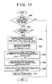
- the procedure of a process in the fourth method will be described with reference to a flowchart shown in FIG. 17 .
- the flowchart of FIG. 17 illustrates a process in which the amount of pumping loss is taken into account in the correction of friction torque in the second method.
- step S 40 it is determined whether it is presently the time to calculate a friction torque at the time of stop of the engine. Specifically, it is determined whether the present time is after the change of the ignition switch 46 from the on-state to the off-state and after the last explosion of fuel. If it is presently the time to calculate friction torque at the time of stop of the engine, the process proceeds to step S 41 . Conversely, if it is presently not the time to calculate friction torque, the process ends.
- step S 41 it is determined whether the present crank angle position coincides with the timing to calculate the lost torque T ac . Specifically, it is determined whether the present crank angle is in either the state where the crank angle is equal to or greater than TDC+10° or the state where the crank angle is equal to or greater than BDC+10°. If the present crank angle coincides with the torque calculation timing, the process proceeds to step S 42 . If the present crank angle does not coincide with the torque calculation timing, the process ends.
- step S 42 parameters needed for the calculation of torque are acquired.
- the parameters acquired include the engine rotation speed (Ne(k)), the coolant temperature (thw(k)), the angular speeds ( ⁇ 0 (k), ⁇ 0 (k+1)), the time ( ⁇ t), etc.
- a friction torque T f (k) is estimated from the map shown in FIG. 4 .
- the friction torque T f (k) is determined from the map of FIG. 4 through the use of the engine rotation speed (Ne(k)) and the coolant temperature (thw(k)) acquired in step S 42 .
- step S 44 the dynamic lost torque T ac (k) attributed to angular acceleration is calculated.
- step S 45 the pumping loss is calculated.
- the torque T ipl (k) corresponding to the amount of pumping loss is calculated using the equation (6).
- step S 46 the actual friction torque T fw (k) is determined by subtracting the lost torque T ac (k) from the torque T ipl (k) corresponding to the amount of pumping loss.
- T ipl (k) is added to the left-hand side of the equation (5), so that the actual friction torque T fw (k) is calculated as the difference between the lost torque T ac (k) and the torque T ipl (k) corresponding to the amount of pumping loss.
- step S 47 the friction torque T f of the map of FIG. 4 is corrected. Specifically, the actual friction torque T fw (k) determined in step S 46 is compared with the friction torque T f (k) determined in step S 43 . If there is a difference between the two friction torques, the map shown in FIG. 4 is corrected through the use of the actual friction torque T fw (k) determined in step S 46 . After the friction torque T f is corrected in step S 47 , the process ends.
- the correction of friction torque factoring in the pumping loss is applied to the second method
- the correction of friction torque factoring in the pumping loss may also be applied to the first and third methods as mentioned above.
- the torque T ipl (k) corresponding to the amount of pumping loss is taken into account in the calculation of the actual friction torque Tfw(k), so that the friction characteristic of the map shown in FIG. 4 can be corrected with high precision. Therefore, it becomes possible to calculate a characteristic value, such as the indicated torque or the like, with high precision.
- Embodiment 5 A fifth method for correction of the friction torque T f will next be described.
- the amount of intake air is controlled so as to minimize the pumping loss.
- a pumping loss in the intake passageway 12 affect the precision in calculation of the actual friction torque T fw (k) in some cases.
- the throttle valve 22 is fully opened to minimize occurrence of a pumping loss.
- step S 51 it is determined whether it is presently the time to calculate a friction torque at the time of stop of the engine. Specifically, it is determined whether the present time is after the change of the ignition switch 46 from the on-state to the off-state and after the last explosion of fuel. If it is presently the time to calculate friction torque at the time of stop of the engine, the process proceeds to step S 52 . Conversely, if it is presently not the time to calculate friction torque, the process ends.
- step S 52 the throttle valve 22 is fully opened in accordance with a command from the ECU 40 .
- step S 53 it is determined whether it is presently the timing to calculate the lost torque.
- the processing of step S 53 is substantially the same as the processing of step S 21 in FIG. 13 . If it is determined in step S 53 that it is presently the torque calculation timing, the process proceeds to step S 54 , in which a friction correction logic is executed. That is, in step S 54 , the process of steps S 22 to S 26 in FIG. 13 is executed. After the friction correction logic is executed in step S 54 , the process ends.
- the throttle valve 22 is fully opened if it is determined that it is presently the time to calculate a friction torque at the time of stop of the engine. Therefore, the amount of air taken into the cylinders can be controlled. Hence, it becomes possible to minimize occurrence of a pumping loss in the intake passageway 12 . Furthermore, according to the process illustrated in FIG. 18 , the influence of the pumping loss on the precision in calculation of the actual friction torque T fw can be minimized by executing the friction correction logic while the throttle valve 22 is kept fully open as in the second method. Therefore, the friction characteristic of the map can be corrected with high precision. Hence, it becomes possible to calculate a characteristic value, such as the indicated torque or the like, with high precision.
- the amount of intake air is controlled at the time of stop of the engine by fully opening the throttle valve 22
- the amount of intake air may also be controlled by other methods, for example, a method in which the lift of the intake valves is controlled, or the like.
- control of the amount of intake air in Embodiment 5 may also be applied to the friction torque correction in the first and third methods. Furthermore, the control of the amount of intake air in Embodiment 5 may be employed in a combination with the friction torque correction factoring in the pumping loss according to the fourth method.
Abstract
Description
[Math. 1]
[Math. 3]
[Math. 4]
[Math. 5]
T ipl(k)=C×(Pm(k)−P ATMOSPHERIC)+D (6)
T ipl(k)=C′×(Pm(k)−PBACK(k)) (7)
[Math. 8]
Claims (20)
Applications Claiming Priority (6)
| Application Number | Priority Date | Filing Date | Title |
|---|---|---|---|
| JP2002258145 | 2002-09-03 | ||
| JP2002-258145 | 2002-09-03 | ||
| JP2002258134A JP2004092603A (en) | 2002-09-03 | 2002-09-03 | Combustion state prediction device of internal combustion engine |
| JP2002-258134 | 2002-09-03 | ||
| JP2003114529A JP4567950B2 (en) | 2002-09-03 | 2003-04-18 | Control device for internal combustion engine |
| JP2003-114529 | 2003-04-18 |
Publications (2)
| Publication Number | Publication Date |
|---|---|
| US20040044461A1 US20040044461A1 (en) | 2004-03-04 |
| US6993427B2 true US6993427B2 (en) | 2006-01-31 |
Family
ID=31721294
Family Applications (1)
| Application Number | Title | Priority Date | Filing Date |
|---|---|---|---|
| US10/634,812 Expired - Fee Related US6993427B2 (en) | 2002-09-03 | 2003-08-06 | Combustion state estimating apparatus for internal combustion engine |
Country Status (4)
| Country | Link |
|---|---|
| US (1) | US6993427B2 (en) |
| CN (1) | CN1333164C (en) |
| DE (2) | DE10362187B4 (en) |
| FR (1) | FR2844004B1 (en) |
Cited By (21)
| Publication number | Priority date | Publication date | Assignee | Title |
|---|---|---|---|---|
| US20050033648A1 (en) * | 2001-07-20 | 2005-02-10 | Hua-Ming Jin | Automated listing management |
| US20060229158A1 (en) * | 2005-04-08 | 2006-10-12 | Denso Corporation | Torque control apparatus and vehicle control system having the same |
| US20060225701A1 (en) * | 2005-04-07 | 2006-10-12 | Siemens Aktiengesellschaft | Method for increasing the reproducibility of the start-up during start-stop operation of an internal combustion engine |
| US20080172199A1 (en) * | 2007-01-12 | 2008-07-17 | Ripley Eugene V | Method of efficiently determining pressure-based combustion parameters for an IC engine |
| US20080178844A1 (en) * | 2007-01-25 | 2008-07-31 | Andreas Stihl Ag & Co. Kg | Method for Operating an Internal Combustion Engine |
| US7500470B2 (en) * | 2006-05-11 | 2009-03-10 | Gm Global Technology Operations, Inc. | Cylinder torque balancing for internal combustion engines |
| US20090118966A1 (en) * | 2007-11-02 | 2009-05-07 | Gm Global Technology Operations, Inc. | Method of torque integral control learning and initialization |
| US20090182487A1 (en) * | 2006-04-07 | 2009-07-16 | Haelleberg Roger | method for adjusting a lookup table and a system for controlling an injector of a cylinder in a combustion engine |
| US20090199818A1 (en) * | 2006-06-13 | 2009-08-13 | Kota Sata | Start-up control device for internal combustion engine |
| US7607416B2 (en) * | 2007-03-23 | 2009-10-27 | Fuji Jukogyo Kabushiki Kaisha | Engine control device |
| US7654133B2 (en) | 2006-09-13 | 2010-02-02 | Toyota Jidosha Kabushiki Kaisha | Malfunction diagnostic apparatus and malfunction diagnostic method for combustion improvement device |
| US7654248B2 (en) * | 2006-05-11 | 2010-02-02 | Gm Global Technology Operations, Inc. | Cylinder torque balancing for internal combustion engines |
| US20100191447A1 (en) * | 2007-07-09 | 2010-07-29 | Peugeot Citroën Automobiles SA | Method for starting an internal combustion engine |
| US7809489B2 (en) | 2006-11-08 | 2010-10-05 | Iav Gmbh Ingenieurgesellschaft Auto Und Verkehr | Method for determining the cylinder interior pressure of an internal combustion engine |
| US20110185798A1 (en) * | 2010-11-19 | 2011-08-04 | Ford Global Technologies, Llc | Method for diagnosing fuel injectors |
| US20120067327A1 (en) * | 2010-09-17 | 2012-03-22 | GM Global Technology Operations LLC | Torque limiting engine lubrication protection system |
| US20150211961A1 (en) * | 2014-01-29 | 2015-07-30 | Honda Motor Co., Ltd. | Pumping loss calculation device for internal combustion engine |
| US20160025594A1 (en) * | 2013-03-12 | 2016-01-28 | Taizo Shimada | Method to measure friction loss in engines and method to detect engine driving state |
| US20160069759A1 (en) * | 2014-09-08 | 2016-03-10 | Taizo Shimada | Inertia momentum measurement method for engine and friction loss measurement method for engine |
| US20160363085A1 (en) * | 2015-06-10 | 2016-12-15 | GM Global Technology Operations LLC | Engine torque control with fuel mass |
| US11473517B1 (en) * | 2021-04-16 | 2022-10-18 | Mitsubishi Electric Corporation | Controller and control method for internal combustion engine |
Families Citing this family (22)
| Publication number | Priority date | Publication date | Assignee | Title |
|---|---|---|---|---|
| DE102004022593B4 (en) | 2004-05-07 | 2007-12-27 | Siemens Ag | Method and device for controlling an internal combustion engine |
| FR2877045B1 (en) * | 2004-10-27 | 2006-12-29 | Renault Sas | METHOD OF ESTIMATING THE MOTOR PUMPING TORQUE |
| US7726281B2 (en) * | 2006-05-11 | 2010-06-01 | Gm Global Technology Operations, Inc. | Cylinder pressure sensor diagnostic system and method |
| FR2917459A3 (en) * | 2007-06-12 | 2008-12-19 | Renault Sas | Drift and dispersion correcting method for vehicle, involves comparing two air flows, and calculating correction to be subjected to first air flow that is measured by using air flow measuring device |
| US8437927B2 (en) * | 2009-09-01 | 2013-05-07 | GM Global Technology Operations LLC | System and method for determining engine friction |
| FR2956161B1 (en) * | 2010-02-09 | 2012-02-03 | Peugeot Citroen Automobiles Sa | METHOD FOR CONTROLLING AN OPERATING PARAMETER OF AN ENGINE AND CONTROL SYSTEM IMPLEMENTING SAID METHOD |
| DE102010018849A1 (en) * | 2010-04-30 | 2011-11-03 | Gm Global Technology Operations Llc (N.D.Ges.D. Staates Delaware) | Control module, particularly vehicle control system for controlling machine functions, comprises determination module for determining momentary crankshaft acceleration, and machine parameter adjusting module, which stops machine parameter |
| CN102269071A (en) * | 2010-06-04 | 2011-12-07 | 通用汽车环球科技运作公司 | Method for controlling functions of engine based on crankshaft acceleration and control system |
| JP5660143B2 (en) * | 2011-02-18 | 2015-01-28 | トヨタ自動車株式会社 | Control device for internal combustion engine |
| EP2530287A1 (en) * | 2011-05-30 | 2012-12-05 | Ford Global Technologies, LLC | Apparatus and method for estimating a combustion torque of an internal combustion engine |
| JP5962463B2 (en) * | 2012-11-27 | 2016-08-03 | 三菱自動車工業株式会社 | Engine start determination device |
| FR3005999B1 (en) * | 2013-05-27 | 2016-11-11 | Peugeot Citroen Automobiles Sa | METHOD OF ESTIMATING THE TORQUE OF LOSSES BY PUMPING A HYBRID MOTOR POWERTRAIN |
| JP6225934B2 (en) * | 2015-02-27 | 2017-11-08 | トヨタ自動車株式会社 | Control device for internal combustion engine |
| CN105115732B (en) * | 2015-07-22 | 2018-01-30 | 观致汽车有限公司 | Method of estimation and device for explosive motor unusual condition |
| JP6012892B1 (en) * | 2016-01-20 | 2016-10-25 | 三菱電機株式会社 | Control device and control method for internal combustion engine |
| CN106194470B (en) * | 2016-08-30 | 2019-02-12 | 潍柴动力股份有限公司 | A kind of modification method and correcting device of engine spray advance angle |
| JP6190936B1 (en) * | 2016-09-27 | 2017-08-30 | 三菱電機株式会社 | Control device and control method for internal combustion engine |
| US10731582B2 (en) * | 2016-11-16 | 2020-08-04 | GM Global Technology Operations LLC | Determination of engine parameter based on determining a metric over three or more cylinder combustion cycles |
| FR3087495A1 (en) * | 2018-10-22 | 2020-04-24 | Continental Automotive France | METHOD AND SYSTEM FOR MONITORING A VEHICLE ENGINE SPEED |
| JP2021032115A (en) * | 2019-08-22 | 2021-03-01 | トヨタ自動車株式会社 | Vehicular learning control system, vehicular control device, and vehicular learning device |
| JP2021032114A (en) * | 2019-08-22 | 2021-03-01 | トヨタ自動車株式会社 | Vehicular learning control system, vehicular control device, and vehicular learning device |
| US11629659B2 (en) * | 2021-06-14 | 2023-04-18 | Ford Global Technologies, Llc | Methods and system to shutdown an engine |
Citations (12)
| Publication number | Priority date | Publication date | Assignee | Title |
|---|---|---|---|---|
| WO1995007450A1 (en) | 1993-09-07 | 1995-03-16 | Motorola Inc. | System to determine engine misfire |
| JPH09303243A (en) | 1996-05-17 | 1997-11-25 | Nissan Motor Co Ltd | Controller for internal combustion engine |
| US5735241A (en) * | 1996-02-29 | 1998-04-07 | Fuji Jukogyo Kabushiki Kaisha | Start up control system for direct fuel injection engine and the method thereof |
| US5915272A (en) | 1993-08-02 | 1999-06-22 | Motorola Inc. | Method of detecting low compression pressure responsive to crankshaft acceleration measurement and apparatus therefor |
| JPH11294213A (en) | 1998-04-03 | 1999-10-26 | Mazda Motor Corp | Control device for power train |
| US6024070A (en) | 1998-09-01 | 2000-02-15 | Chrysler Corporation | Individual cylinder idle spark control |
| US6062190A (en) * | 1997-07-18 | 2000-05-16 | Nissan Motor Co., Ltd. | Ignition timing control apparatus and method for internal combustion engine |
| US6070567A (en) | 1996-05-17 | 2000-06-06 | Nissan Motor Co., Ltd. | Individual cylinder combustion state detection from engine crankshaft acceleration |
| JP2001098986A (en) | 1999-09-30 | 2001-04-10 | Nissan Motor Co Ltd | Friction estimating device for engine, and fuel consumption diagnosic device for engine |
| JP2001098997A (en) | 1999-10-01 | 2001-04-10 | Nissan Motor Co Ltd | Device for estimating friction of engine, and device for diagnosing fuel consumption |
| JP2001227398A (en) | 2000-02-15 | 2001-08-24 | Denso Corp | Control device for internal combustion engine |
| US6622692B2 (en) * | 2000-03-14 | 2003-09-23 | Isuzu Motors Limited | Common rail fuel injection device |
-
2003
- 2003-08-06 US US10/634,812 patent/US6993427B2/en not_active Expired - Fee Related
- 2003-09-02 DE DE10362187.3A patent/DE10362187B4/en not_active Expired - Fee Related
- 2003-09-02 DE DE10340439.2A patent/DE10340439B8/en not_active Expired - Fee Related
- 2003-09-03 CN CNB031579477A patent/CN1333164C/en not_active Expired - Fee Related
- 2003-09-03 FR FR0310431A patent/FR2844004B1/en not_active Expired - Fee Related
Patent Citations (12)
| Publication number | Priority date | Publication date | Assignee | Title |
|---|---|---|---|---|
| US5915272A (en) | 1993-08-02 | 1999-06-22 | Motorola Inc. | Method of detecting low compression pressure responsive to crankshaft acceleration measurement and apparatus therefor |
| WO1995007450A1 (en) | 1993-09-07 | 1995-03-16 | Motorola Inc. | System to determine engine misfire |
| US5735241A (en) * | 1996-02-29 | 1998-04-07 | Fuji Jukogyo Kabushiki Kaisha | Start up control system for direct fuel injection engine and the method thereof |
| JPH09303243A (en) | 1996-05-17 | 1997-11-25 | Nissan Motor Co Ltd | Controller for internal combustion engine |
| US6070567A (en) | 1996-05-17 | 2000-06-06 | Nissan Motor Co., Ltd. | Individual cylinder combustion state detection from engine crankshaft acceleration |
| US6062190A (en) * | 1997-07-18 | 2000-05-16 | Nissan Motor Co., Ltd. | Ignition timing control apparatus and method for internal combustion engine |
| JPH11294213A (en) | 1998-04-03 | 1999-10-26 | Mazda Motor Corp | Control device for power train |
| US6024070A (en) | 1998-09-01 | 2000-02-15 | Chrysler Corporation | Individual cylinder idle spark control |
| JP2001098986A (en) | 1999-09-30 | 2001-04-10 | Nissan Motor Co Ltd | Friction estimating device for engine, and fuel consumption diagnosic device for engine |
| JP2001098997A (en) | 1999-10-01 | 2001-04-10 | Nissan Motor Co Ltd | Device for estimating friction of engine, and device for diagnosing fuel consumption |
| JP2001227398A (en) | 2000-02-15 | 2001-08-24 | Denso Corp | Control device for internal combustion engine |
| US6622692B2 (en) * | 2000-03-14 | 2003-09-23 | Isuzu Motors Limited | Common rail fuel injection device |
Cited By (35)
| Publication number | Priority date | Publication date | Assignee | Title |
|---|---|---|---|---|
| US20050033648A1 (en) * | 2001-07-20 | 2005-02-10 | Hua-Ming Jin | Automated listing management |
| US20060225701A1 (en) * | 2005-04-07 | 2006-10-12 | Siemens Aktiengesellschaft | Method for increasing the reproducibility of the start-up during start-stop operation of an internal combustion engine |
| US7134412B2 (en) * | 2005-04-07 | 2006-11-14 | Siemens Aktiengesellschaft | Method for increasing the reproducibility of the start-up during start-stop operation of an internal combustion engine |
| US20060229158A1 (en) * | 2005-04-08 | 2006-10-12 | Denso Corporation | Torque control apparatus and vehicle control system having the same |
| US7236874B2 (en) * | 2005-04-08 | 2007-06-26 | Denso Corporation | Torque control apparatus and vehicle control system having the same |
| US7991537B2 (en) * | 2006-04-07 | 2011-08-02 | Scania Cv Ab | Method for adjusting a lookup table and a system for controlling an injector of a cylinder in a combustion engine |
| US20090182487A1 (en) * | 2006-04-07 | 2009-07-16 | Haelleberg Roger | method for adjusting a lookup table and a system for controlling an injector of a cylinder in a combustion engine |
| US7500470B2 (en) * | 2006-05-11 | 2009-03-10 | Gm Global Technology Operations, Inc. | Cylinder torque balancing for internal combustion engines |
| US7654248B2 (en) * | 2006-05-11 | 2010-02-02 | Gm Global Technology Operations, Inc. | Cylinder torque balancing for internal combustion engines |
| US20090199818A1 (en) * | 2006-06-13 | 2009-08-13 | Kota Sata | Start-up control device for internal combustion engine |
| US7822536B2 (en) * | 2006-06-13 | 2010-10-26 | Toyota Jidosha Kabushiki Kaisha | Start-up control device for internal combustion engine |
| US7654133B2 (en) | 2006-09-13 | 2010-02-02 | Toyota Jidosha Kabushiki Kaisha | Malfunction diagnostic apparatus and malfunction diagnostic method for combustion improvement device |
| US7809489B2 (en) | 2006-11-08 | 2010-10-05 | Iav Gmbh Ingenieurgesellschaft Auto Und Verkehr | Method for determining the cylinder interior pressure of an internal combustion engine |
| US7440841B2 (en) * | 2007-01-12 | 2008-10-21 | Delphi Technologies, Inc. | Method of efficiently determining pressure-based combustion parameters for an IC engine |
| US20080172199A1 (en) * | 2007-01-12 | 2008-07-17 | Ripley Eugene V | Method of efficiently determining pressure-based combustion parameters for an IC engine |
| US20080178844A1 (en) * | 2007-01-25 | 2008-07-31 | Andreas Stihl Ag & Co. Kg | Method for Operating an Internal Combustion Engine |
| US7637248B2 (en) * | 2007-01-25 | 2009-12-29 | Andreas Stihl Ag & Co. Kg | Method for operating an internal combustion engine by determining and counteracting a pre-ignition state |
| US7607416B2 (en) * | 2007-03-23 | 2009-10-27 | Fuji Jukogyo Kabushiki Kaisha | Engine control device |
| US20100191447A1 (en) * | 2007-07-09 | 2010-07-29 | Peugeot Citroën Automobiles SA | Method for starting an internal combustion engine |
| US8600649B2 (en) * | 2007-07-09 | 2013-12-03 | Peugeot Citroen Automobiles Sa | Method for starting an internal combustion engine |
| US20090118966A1 (en) * | 2007-11-02 | 2009-05-07 | Gm Global Technology Operations, Inc. | Method of torque integral control learning and initialization |
| US7788024B2 (en) * | 2007-11-02 | 2010-08-31 | Gm Global Technology Operations, Inc. | Method of torque integral control learning and initialization |
| US20120067327A1 (en) * | 2010-09-17 | 2012-03-22 | GM Global Technology Operations LLC | Torque limiting engine lubrication protection system |
| US8602001B2 (en) * | 2010-09-17 | 2013-12-10 | GM Global Technology Operations LLC | Torque limiting engine lubrication protection system |
| US20110185798A1 (en) * | 2010-11-19 | 2011-08-04 | Ford Global Technologies, Llc | Method for diagnosing fuel injectors |
| US8051704B2 (en) | 2010-11-19 | 2011-11-08 | Ford Global Technologies, Llc | Method for diagnosing fuel injectors |
| US8459105B2 (en) | 2010-11-19 | 2013-06-11 | Ford Global Technologies, Llc | Method for diagnosing fuel injectors |
| US20160025594A1 (en) * | 2013-03-12 | 2016-01-28 | Taizo Shimada | Method to measure friction loss in engines and method to detect engine driving state |
| US20150211961A1 (en) * | 2014-01-29 | 2015-07-30 | Honda Motor Co., Ltd. | Pumping loss calculation device for internal combustion engine |
| US9599536B2 (en) * | 2014-01-29 | 2017-03-21 | Honda Motor Co., Ltd. | Pumping loss calculation device for internal combustion engine |
| US20160069759A1 (en) * | 2014-09-08 | 2016-03-10 | Taizo Shimada | Inertia momentum measurement method for engine and friction loss measurement method for engine |
| US20160363085A1 (en) * | 2015-06-10 | 2016-12-15 | GM Global Technology Operations LLC | Engine torque control with fuel mass |
| US9689339B2 (en) * | 2015-06-10 | 2017-06-27 | GM Global Technology Operations LLC | Engine torque control with fuel mass |
| US11473517B1 (en) * | 2021-04-16 | 2022-10-18 | Mitsubishi Electric Corporation | Controller and control method for internal combustion engine |
| US20220333538A1 (en) * | 2021-04-16 | 2022-10-20 | Mitsubishi Electric Corporation | Controller and control method for internal combustion engine |
Also Published As
| Publication number | Publication date |
|---|---|
| FR2844004A1 (en) | 2004-03-05 |
| CN1333164C (en) | 2007-08-22 |
| CN1492134A (en) | 2004-04-28 |
| DE10362187B4 (en) | 2016-06-02 |
| FR2844004B1 (en) | 2006-07-28 |
| US20040044461A1 (en) | 2004-03-04 |
| DE10340439A1 (en) | 2004-04-22 |
| DE10340439B4 (en) | 2016-09-22 |
| DE10340439B8 (en) | 2017-01-12 |
Similar Documents
| Publication | Publication Date | Title |
|---|---|---|
| US6993427B2 (en) | Combustion state estimating apparatus for internal combustion engine | |
| US7809493B2 (en) | Stop position control apparatus for internal combustion engine | |
| US7027911B2 (en) | Apparatus for controlling engine rotation stop by estimating kinetic energy and stop position | |
| JP4567950B2 (en) | Control device for internal combustion engine | |
| JP4066971B2 (en) | Control device for internal combustion engine | |
| US20070232444A1 (en) | Stopping position control apparatus and stopping position control method of internal combustion engine | |
| EP1439300A1 (en) | Engine control device | |
| US20140007855A1 (en) | Internal egr amount calculation device for internal combustion engine | |
| US6672284B2 (en) | Fuel supply amount control apparatus for internal combustion engine | |
| US8639452B2 (en) | Burned-gas passage amount computing method and system used in exhaust gas recirculation system | |
| JP4251039B2 (en) | Combustion state estimation device for internal combustion engine | |
| JP4200868B2 (en) | Fuel property determination device for internal combustion engine | |
| US6729304B2 (en) | Fuel injection control system, fuel injection control method, and engine control unit, for internal combustion engine | |
| JP4135504B2 (en) | Control device for internal combustion engine | |
| JP2004245106A (en) | Kinetic energy predicting device for internal combustion engine | |
| JP4211487B2 (en) | Control device for internal combustion engine | |
| JP2004092603A (en) | Combustion state prediction device of internal combustion engine | |
| JP2021017862A (en) | Lubrication oil deterioration determination device | |
| JP4927697B2 (en) | Fuel property estimation device for internal combustion engine | |
| JP4702085B2 (en) | Combustion state estimation device for internal combustion engine | |
| JP2006207538A (en) | Ignition timing control device for internal combustion engine | |
| JP2005330837A (en) | Control device for internal combustion engine | |
| US9856807B2 (en) | Control apparatus for internal combustion engine, and control method for internal combustion engine | |
| JP2657713B2 (en) | Fuel leak diagnosis system for electronically controlled fuel injection type internal combustion engine | |
| JP4419975B2 (en) | Control device for internal combustion engine |
Legal Events
| Date | Code | Title | Description |
|---|---|---|---|
| AS | Assignment |
Owner name: TOYOTA JIDOSHA KABUSHIKI KAISHA, JAPAN Free format text: ASSIGNMENT OF ASSIGNORS INTEREST;ASSIGNOR:UEDA, KOICHI;REEL/FRAME:014379/0663 Effective date: 20030731 |
|
| FEPP | Fee payment procedure |
Free format text: PAYOR NUMBER ASSIGNED (ORIGINAL EVENT CODE: ASPN); ENTITY STATUS OF PATENT OWNER: LARGE ENTITY |
|
| FPAY | Fee payment |
Year of fee payment: 4 |
|
| FPAY | Fee payment |
Year of fee payment: 8 |
|
| FEPP | Fee payment procedure |
Free format text: MAINTENANCE FEE REMINDER MAILED (ORIGINAL EVENT CODE: REM.) |
|
| LAPS | Lapse for failure to pay maintenance fees |
Free format text: PATENT EXPIRED FOR FAILURE TO PAY MAINTENANCE FEES (ORIGINAL EVENT CODE: EXP.) |
|
| STCH | Information on status: patent discontinuation |
Free format text: PATENT EXPIRED DUE TO NONPAYMENT OF MAINTENANCE FEES UNDER 37 CFR 1.362 |
|
| FP | Lapsed due to failure to pay maintenance fee |
Effective date: 20180131 |