US6996489B2 - Method and apparatus for sampling a power supply current of an integrated circuit, and storage medium onto which is recorded a control program therefor - Google Patents
Method and apparatus for sampling a power supply current of an integrated circuit, and storage medium onto which is recorded a control program therefor Download PDFInfo
- Publication number
- US6996489B2 US6996489B2 US09/796,451 US79645101A US6996489B2 US 6996489 B2 US6996489 B2 US 6996489B2 US 79645101 A US79645101 A US 79645101A US 6996489 B2 US6996489 B2 US 6996489B2
- Authority
- US
- United States
- Prior art keywords
- power supply
- supply current
- sampling
- test signal
- current value
- Prior art date
- Legal status (The legal status is an assumption and is not a legal conclusion. Google has not performed a legal analysis and makes no representation as to the accuracy of the status listed.)
- Expired - Lifetime, expires
Links
Images


Classifications
-
- G—PHYSICS
- G01—MEASURING; TESTING
- G01R—MEASURING ELECTRIC VARIABLES; MEASURING MAGNETIC VARIABLES
- G01R31/00—Arrangements for testing electric properties; Arrangements for locating electric faults; Arrangements for electrical testing characterised by what is being tested not provided for elsewhere
- G01R31/28—Testing of electronic circuits, e.g. by signal tracer
- G01R31/317—Testing of digital circuits
- G01R31/3181—Functional testing
- G01R31/319—Tester hardware, i.e. output processing circuits
- G01R31/3193—Tester hardware, i.e. output processing circuits with comparison between actual response and known fault free response
- G01R31/31935—Storing data, e.g. failure memory
-
- G—PHYSICS
- G01—MEASURING; TESTING
- G01R—MEASURING ELECTRIC VARIABLES; MEASURING MAGNETIC VARIABLES
- G01R31/00—Arrangements for testing electric properties; Arrangements for locating electric faults; Arrangements for electrical testing characterised by what is being tested not provided for elsewhere
- G01R31/28—Testing of electronic circuits, e.g. by signal tracer
- G01R31/30—Marginal testing, e.g. by varying supply voltage
- G01R31/3004—Current or voltage test
Definitions
- the present invention relates to test technology for an integrated circuit, and more particularly to a method and apparatus for sampling a power supply current for performing frequency analysis of the power supply current flowing in the integrated circuit when a test signal is applied thereto, and to a storage medium onto which is stored a control program for controlling the sampling apparatus.
- a method such as noted above of sampling the power supply current of an integrated circuit was used in the past in order to perform frequency spectrum analysis of the power supply current of the integrated circuit.
- sampling of the power supply current is performed while applying a test pattern to an integrated circuit.
- circuits forming the power supply or current measurement unit and the device under test have capacitive components and inductive components, so that even if the application of the test pattern is ended, power supply current continues to flow for an amount of time established by the time constant of the circuit.
- the present invention adopts the following basic technical constitution.
- the present invention is an apparatus for sampling a power supply current for performing frequency analysis of the power supply current flowing in an integrated circuit to which is applied a test signal, this apparatus having a power supply generating a prescribed supply of power to a power supply terminal of a device under test (DUT), a current detection means for monitoring a power supply current value supplied from the power supply to the DUT and generating a power supply current value signal indicating this value, a test signal generating means for generating a prescribed test signal to be applied to input/output terminals of the DUT other than the power supply terminal and for generating a test signal application signal indicating that the test signal is currently being applied, a sampling means for sampling the power supply current value signal, a sampling time determination means for instructing the sampling means with regard to the start and end of sampling, based on the test signal application signal, a sampled data storage means for storing data sampled by the sampling means, a Fourier transform means for performing a Fourier transformation on the sampled data, and a control means for issuing instructions to various DUT
- the present invention has a time constant information storage means for holding time constant information of the circuit and the sampling time determination means, which indicates to the sampling means, based on the test signal application signal and the time constant information of the time constant information storage means, a time of the start and the end of sampling apparatus.
- the present invention can further have a configuration including a sampled data analysis means which performs analysis of sampled data and establishes the amount of continuation time during which sampling of the power supply current value signal is to be continued after the end of application of the test signal to the DUT.
- the present invention can further have a configuration including a stabilization judgment means, which, based on the sampled data, makes a judgments as to how much time would be required after the end of application of the test signal to the DUT until a time at which the power supply current stops or stabilizes, and determines the extension time for sampling.
- a stabilization judgment means which, based on the sampled data, makes a judgments as to how much time would be required after the end of application of the test signal to the DUT until a time at which the power supply current stops or stabilizes, and determines the extension time for sampling.
- the present invention can further have a configuration including a Fourier transform window information storage means, which stores a range of data of the sampled data to be subjected to a Fourier transformation calculation.
- the present invention can further have a configuration including a time constant information storage means storing and holding circuit time constant information and a Fourier transform window determination means, which, based on the time constant information, determines a range of data of the sampled data to be subjected to a Fourier transformation calculation.
- the present invention can further have a configuration including a sampled data analysis means analyzing the sampled data and a Fourier transform window determination means, which, from the sampled data analysis results thereof, determines a range of data of the sample data to be subjected to a Fourier transformation calculation.
- the present invention can further have a configuration including a stabilization judgment means, which judges approximately how much time would be required after the end of application of the test signal to the DUT until a time when the power supply current stops or stabilizes, and a Fourier transform window determination means, which, from the results from the stabilization judgment means, determines a range of data of the sampled data to be subjected to a Fourier transformation calculation.
- a stabilization judgment means which judges approximately how much time would be required after the end of application of the test signal to the DUT until a time when the power supply current stops or stabilizes
- a Fourier transform window determination means which, from the results from the stabilization judgment means, determines a range of data of the sampled data to be subjected to a Fourier transformation calculation.
- An apparatus for sampling the power supply current of an integrated circuit is an apparatus that samples a value of power supply current flowing in the integrated circuit when a test signal is applied to the integrated circuit, wherein sampling of the power supply current is not only performed during the time when the test signal is applied to the integrated circuit, but is also continued after the end of application of the test signal, this apparatus having a test signal generation means (reference numeral 2 in FIG. 1 of the accompanying drawings), which generates a test signal, a device under test (DUT; reference numeral 1 in FIG. 1 ), a power supply (reference numeral 5 in FIG. 1 ) which supplies a prescribed power to the integrated circuit, a current detection means (reference numeral 4 in FIG.
- a sampling means which detects a value of the power supply current supplied to the integrated circuit from the power supply
- a sampling means (reference numeral 7 in FIG. 1 ), which sampling the power supply current value detected by the power supply current detection means, a sampling time determination means (reference numeral 6 in FIG. 1 ), which instructs the sampling means with regard to the start and end of sampling
- a sampled data storage means (reference numeral 8 in FIG. 1 ), which holds values of sampled data
- a Fourier transform means reference numeral 9 in FIG. 1
- a control means which controls the overall apparatus.
- a method for sampling a power supply current of an integrated circuit is a method for sampling the power supply current flowing in the integrated circuit when a test signal is applied to the integrated circuit, this method not only sampling the power supply current during the time when the test signal is applied to the integrated circuit, but also continuing to sample the power supply current value even after the end of application of the test signal to the integrated circuit, the method being formed by generating a prescribed power supply voltage for the integrated circuit and supplying the, voltage to the integrated circuit (step S 101 of FIG. 9 of the accompanying drawings), generating a test signal to be applied to the integrated circuit and supplying the test signal to the integrated circuit (stepS 102 in FIG.
- step S 103 of FIG. 9 generating a test signal application signal indicating that the test signal is applied
- step S 104 of FIG. 9 monitoring the power supply current value flowing in the integrated circuit and generating a power supply current value signal
- step S 104 of FIG. 9 starting sampling of the power supply current value signal
- step S 105 of FIG. 9 ending the generation of a the test signal upon generation and application of a pre-established test signal
- step S 106 of FIG. 9 determining the time of ending the sampling of the power supply current value signal (step S 107 of FIG. 9 ), stopping the sampling of the power supply current value signal (step S 108 of FIG. 9 ), performing a Fourier transform processing on sampled data (step S 109 of FIG. 9 ), and stopping the supply of power (step S 110 of FIG. 9 ).
- a storage medium according to the present invention is a storage medium onto which is stored a program for execution under computer control of processing for sampling of a power supply current value for frequency analysis of the power supply current flowing in an integrated circuit when a test signal is applied to the integrated circuit by a power supply current sampling apparatus, this processing being:
- the program can be read into the computer from the storage medium (for example, CD-ROM, DVD, floppy disk, hard disk, magnetic tape, or semiconductor memory) into which the above-noted program is stored and then executed, or downloaded to the computer from a communication network, via a server or the like and then executed.
- the storage medium for example, CD-ROM, DVD, floppy disk, hard disk, magnetic tape, or semiconductor memory
- a method for sampling the value of power supply current flowing in an integrated circuit when a test signal is applied to the integrated circuit not only samples the power supply current value during the time when a test signal is applied to the integrated circuit, but also continues to sample the power supply current value after the end of application of the test signal, thereby obtaining complete information with regard to the power supply current value.
- a power supply generates prescribed power for an integrated circuit, and supplies this power to the integrated circuit.
- the test signal generation means generates a test signal for application to the integrated circuit, and applies the test signal to the integrated circuit, and also generates a test signal application signal that indicates that the test signal is currently value being applied.
- a current monitoring means monitors the power supply current flowing in the integrated circuit and generates a power supply current value signal, which is sampled by the sampling means.
- the timing of the start and end of sampling are controlled so that the timing starts with the start of application of the test signal, as indicated by the test signal application signal, and ends when a prescribed amount of time has elapsed after the end of the test signal application.
- This timing of the start and end of sampling is established by the sampling time determination means.
- the sampled data are first stored in the sampled data storage means, after which a frequency spectrum is ultimately obtained by the Fourier transform means.
- a frequency spectrum is ultimately obtained by the Fourier transform means.
- FIG. 1 is drawing showing a first embodiment of the present invention.
- FIG. 2 is drawing showing a second embodiment of the present invention.
- FIG. 3 is drawing showing a third embodiment of the present invention.
- FIG. 4 is drawing showing a fourth embodiment of the present invention.
- FIG. 5 is drawing showing a fifth embodiment of the present invention.
- FIG. 6 is drawing showing a sixth embodiment of the present invention.
- FIG. 7 is drawing showing a seventh embodiment of the present invention.
- FIG. 8 is drawing showing a eighth embodiment of the present invention.
- FIG. 9 is a flowchart showing the operation of the first embodiment of the present invention.
- FIG. 10 is a drawing illustrating the operation of the first embodiment of the present invention.
- FIG. 11 is a drawing illustrating the operation of the first embodiment of the present invention.
- FIG. 12 is a flowchart showing the operation of the second embodiment of the present invention.
- FIG. 13 is a flowchart showing the operation of the third embodiment of the present invention.
- FIG. 14 is a flowchart showing the operation of the fourth embodiment of the present invention.
- FIG. 15 is a flowchart showing the operation of the fifth embodiment of the present invention.
- FIG. 16 is a flowchart showing the operation of the sixth embodiment of the present invention.
- FIG. 17 is a flowchart showing the operation of the seventh embodiment of the present invention.
- FIG. 18 is a flowchart showing the operation of the eighth embodiment of the present invention.
- FIG. 1 is a drawing showing the configuration of a first embodiment of the present invention.
- the sampling apparatus according to the first embodiment of the present invention has a main control means 1 , a test signal generation means 2 , a device under test (DUT) 3 , a current detection means 4 , a power supply 5 , a sampling time determination means 6 , a sampling means 7 , a sampled data storage means 8 , and a Fourier transform means 9 .
- the test signal generation means 2 in response to an instruction from the main control means 1 , generates a pre-established test signal, and applies the test signal to prescribed input/output terminals, exclusive of power supply terminals, of the device under test (DUT) 3 . During the time in which the test signal is applied to the DUT 3 , the test signal generation means 2 generates a test signal application signal indicating that the test signal is currently being applied.
- the power supply 5 in response to an instruction from the main control means 1 , generates a prescribed voltage, and supplies this voltage to the DUT 3 , via the current detection means 4 .
- the current detection means 4 monitors the power supply current supplied to the DUT 3 , generates a signal (the power supply current value signal) indicating this value, and transmits this to the sampling means 7 .
- the sampling time determination means 6 in response to an instruction from the main control means 1 and based on test signal application signal from the test signal generation means 2 indicating application of the test signal, instructs the sampling means 7 with regard to the start and end of sampling of the power supply current value signal.
- the sampled power supply current value signal is sent to and stored in the sampled data storage means 8 .
- the Fourier transform means 9 executes a discrete Fourier transformation (or fast Fourier transformation (FFT)) on the sampled data stored in the sampled data storage means 8 , and outputs a frequency spectrum of the power supply current.
- FFT fast Fourier transformation
- the main control means 1 outputs instructions to the various other means, and controls the overall operation of the apparatus.
- FIG. 9 is a flowchart illustrating the operation of the first embodiment of the present invention
- FIG. 10 is a drawing illustrating the operation of the first embodiment. The operation of the first embodiment is described in detail below, with references made to FIG. 1 , FIG. 9 , and FIG. 10 .
- an instruction from the main control means 1 causes the power supply 5 to generate a pre-established voltage, this power supply voltage being applied to a power supply terminal of the DUT 3 via the current detection means 4 (step S 101 in FIG. 9 ).
- This power supply voltage is not restricted to a constant voltage, and can alternatively be a voltage that changes with time.
- test signal generation means 2 starts to generate a pre-established test signal in response to an instruction from the main control means 1 , this test signal being applied to input/output terminals other than a power supply terminal of the DUT 3 (step S 102 of FIG. 9 ).
- test signal generation means 2 upon the start of application of the test signal a test signal application signal indicating that the test signal is being applied is generated, this being transmitted to the sampling time determination means 6 (step S 103 in FIG. 9 ).
- the current generated by the power supply 5 and supplied to the DUT 3 is constantly monitored and a power supply current value signal indicating the size of this current value is generated, this being transmitted to the sampling means 7 (step S 104 in FIG. 9 ).
- the sampling time determination means 6 upon receiving the test signal application signal from the test signal generation means 2 , simultaneously with start of the application of the test signal, an instruction is given to the sampling means 7 for the start of sampling of the power supply current value signal.
- sampling means 7 in accordance with a sampling start instruction the sampling of the power supply current value signal is started (time A in FIG. 10 ), and sampled values are successively sent to the sampled data storage means 8 (step S 105 in FIG. 9 ).
- the test signal generation means 2 ends generation of the test signal and the application of the test signal to the DUT 3 is ended. Upon the end of application of the test signal, the generation of the test signal application signal is also ended (step S 106 in FIG. 9 ).
- the sampling time determination means 6 in response to the test signal application signal and an instruction from the main control means 1 , instructs the sampling means 7 to end sampling (stepS 107 in FIG. 9 ).
- the sampling means 7 Upon receiving the sampling end instruction, the sampling means 7 ends sampling of the power supply current value signal (step S 108 in FIG. 9 ).
- step S 110 in FIG. 9 the generation of the power supply by the power supply 5 is ended.
- control program is stored into a storage medium (not shown in the drawing) such as a ROM or floppy disk attached to the main control means 1 , this program being then loaded into the main control means.
- This time constant means that even after the application of the test signal to the DUT is ended (at time B) and the DUT operation stops, there is a power supply current detected by the current detection means, the flow of this current stopping (or stabilizing) when a certain amount of time has elapsed (at time C). For this reason, in order to obtain frequency spectrum information of the power supply current resulting from operation of the DUT with the application of a test signal, it is necessary to sample the power supply current value signal up until the time C and perform a discreet Fourier transformation based on the obtained sampled data, so as to obtain a frequency spectrum of the power supply current.
- sampling of the power supply current value signal is continued for a certain amount of time, making it possible to obtain an accurate frequency spectrum of the power supply current.
- FIG. 2 is shows the configuration of the second embodiment.
- the second embodiment in contrast to the first embodiment, shown in FIG. 1 , has the addition of a time constant information storage means 10 .
- the time constant information storage means 10 stores and holds the time constant information of the circuitry forming the power supply 5 , the current detection means 4 , and the DUT 3 , and, in response to an instruction from the main control means 1 , sends the time constant information.
- Other parts of the configuration are the same as the configuration of the first embodiment as shown in FIG. 1 .
- FIG. 12 is a flowchart illustrating the operation of the second embodiment. Because steps S 201 to S 206 and steps S 208 to S 210 are the same as steps S 101 to S 106 and steps S 108 to S 110 described with regard to the first embodiment, these steps will not be described herein.
- time constant information storage means 10 time constant information of the circuitry forming the power supply 5 , the current detection means 4 , and the DUT 3 is stored.
- the time constant is determined for each type of power supply 5 , current detection means 4 , and DUT 3 , and this is stored in the time constant information storage means 10 .
- the appropriate time constant information is sent to the main control means 1 , and the main control means 1 sends this information to the sampling time determination means 6 .
- the sampling time determination means 6 based on the time constant information sent from the main control means 1 , establishes the sampling extension time (step S 207 in FIG. 12 ).
- This series of operations can be stored as a program of control operations, this control program being then executed by the main control means 1 so as to perform control of the various parts of the apparatus.
- the control program is stored into a storage medium (not shown in the drawing), such as a ROM or floppy disk provided in the main control means 1 , and loaded into the main control means 1 .
- the time constant of the circuitry making up the power supply, the current detection means, and the DUT varies depending on the type of power supply and DUT. Given this situation, the time constant is determined and stored for each DUT, making it possible to immediately obtain the time constant information for each circuit system made up of a power supply, a current detection means, and a DUT. The amount of time required for the power supply current to stop or stabilize after stopping the application of a test signal is determined by the time constant of the circuitry. Because of this, by establishing the time extension of sampling of the power supply current value signal based on the time constant information of the particular circuit, it is possible to easily obtain an accurate frequency spectrum of the power supply current.
- FIG. 3 is a drawing showing the configuration of the third embodiment.
- the third embodiment compared with the first embodiment, has the new addition of a sampled data analysis means 11 .
- the sampled data analysis means 11 analyzes the sampled power supply current data by the sampling means 7 , determines the amount of time extension that should be made to the sampling of the power supply current value signal, and sends that value to the main control means 1 .
- FIG. 13 is a flowchart showing the operation of the third embodiment of the present invention.
- steps S 301 to S 306 , S 308 , S 310 and S 311 are the same as steps S 101 to S 106 and S 108 to S 110 shown in FIG. 9 with regard to the first embodiment, and are therefore not described herein.
- the sampling time determination means 6 in response to the test signal application signal and an instruction from the main control means 1 , issues an instruction to the sampling means 7 so as to stop the sampling at a time that is sufficiently delayed from the end of application of the test signal to the DUT 3 (step S 307 in FIG. 13 ).
- the obtained sampled power supply current data is analyzed, and a determination is made as to how much sampling of the power supply current value signal should be done to be able to obtain accurate power supply current information, thereby determining the required delay time.
- this information is sent by the main control means 1 to the sampling time determination means 6 , so as to extend the sampling time by just the required amount of time, an instruction being accordingly issued to the sampling means 7 end the sampling (step S 307 in FIG. 13 ).
- step S 309 is not executed.
- This series of operations can be coded as a control program of the related control operations, which is executed by the main control means 1 , thereby controlling the operation of various sections of the apparatus.
- the control program is stored into a storage medium (not shown in the drawing) such as a ROM or floppy disk attached to the main control means 1 , this program being then loaded into the main control means.
- the sampling extension time for the sampling of the power supply current value signal is determined by the time constant of the circuitry formed by the power supply, the current detection means, and the DUT. If this time constant is not known with certainty, however, it is not known with certainty how much time the sampling should be extended to obtain accurate capture of the power supply current information. Given this, sampling is performed one time of the power supply current value signal over a sufficient amount of time and the sampled results are analyzed, so as to determine how much time the sampling should be extended in order to obtain accurate power supply current information. That is, in the third embodiment it is possible to reliably obtain power supply current information without knowing the precise time constant of the circuitry.
- FIG. 4 is a drawing showing the configuration of the fourth embodiment.
- the fourth embodiment in comparison with the third embodiment, has, in place of the sampled data analysis means 11 , a stabilization judgment means 12 .
- the stabilization judgment means 12 from the results of sampling the power supply current value signal, analyzes how much time after the end of application of the test signal to the DUT 3 the power supply current stops or stabilizes. Other aspects of the configuration of this embodiment are the same as the third embodiment.
- FIG. 14 is a flowchart showing the operation of the fourth embodiment of the present invention.
- the steps S 401 to S 408 and steps S 410 to S 411 are the same as the steps S 301 to S 308 and steps S 310 to S 311 in FIG. 13 with regard to the third embodiment, and will thus not be described herein.
- the stabilization judgment means 12 analyzes the power supply current value signal sampled data stored in the sampled data storage means 8 , and investigates how much time after the ending of application of the test signal from the test signal generation means 2 to the DUT 3 the power supply current stops or stabilizes. This time value is sent to the main control means 1 (step S 409 in FIG. 14 ). After this time is determined one time, this information is sent from the main control means to the sampling time determination means 6 , which issues an instruction to the sampling means 7 to extend the sampling time before stopping sampling the amount of time required (step S 407 in FIG. 14 ). In this case, the step S 409 of FIG. 14 is not executed.
- This series of operations can be coded as a control program of the related control operations, which is executed by the main control means 1 , thereby controlling the operation of various sections of the apparatus.
- the control program is stored into a storage medium (not shown in the drawing) such as a ROM or floppy disk attached to the main control means 1 , this program being then loaded into the main control means.
- the sampling extension time for the sampling of the power supply current value signal after ending of the application of the test signal to the DUT is determined by the time constant of the circuitry formed by the power supply, the current detection means, and the DUT.
- this time constant is not known with certainty, however, it is not known with certainty how much time the sampling should be extended to obtain accurate capture of the power supply current information.
- sampling is performed one time of the power supply current value signal over a sufficient amount of time and the sampled results are analyzed, so as to determine how much time the sampling should be extended in order to obtain accurate power supply current information. That is, in the fourth embodiment, by extending the sampling by an amount of time so as to achieve stopping or stabilization of the power supply current, it is possible to reliably obtain power supply current information without knowing the precise time constant of the circuitry.
- FIG. 5 is a block diagram showing the configuration of the fifth embodiment.
- the fifth embodiment of the present invention in comparison with the configuration of the first embodiment shown in FIG. 1 , has the addition of a Fourier transform window information storage means. Other aspects of the configuration are the same as the first embodiment.
- the sampling time determination means 6 receives a test signal application signal from the test signal generation means 2 and issues an instruction to the sampling means to start the sampling of the power supply current value signal simultaneously with the start of the application of the test signal to the DUT 3 , and issues an instruction to the sampling means 7 to end the sampling a sufficient time after the end of application of the test signal to the DUT 3 .
- the Fourier transform window information storage means 13 stores information about the range of data of the sampled power supply current value data stored in the sampled data storage means 8 to be subjected to a discrete Fourier transformation. This information is sent to the Fourier transform means 9 , and when the discrete Fourier transformation is performed thereby, it is used to establish the range of data (window) used to transform the sampled data.
- FIG. 15 is a flowchart showing the operation of the fifth embodiment of the present invention.
- steps S 501 to S 506 , S 508 , S 510 , and S 511 are the same as steps S 101 to S 106 and steps S 108 to S 110 of the first embodiment shown in FIG. 1 , and are not described herein.
- the sampling time determination means 6 based on the test signal application signal and an instruction from the main control means 1 , issues an instruction to the sampling means 7 to end sampling at a point in time sufficiently after the end of application of the test signal (step S 507 in FIG. 15 ).
- the Fourier transform window information storage means 13 receives an instruction from the main control means 1 , and issues an instruction to the Fourier transform means 9 regarding the range of sampled data to be subjected to the discrete Fourier transformation. This range (window) is established based on the characteristics of the circuitry formed by the power supply 5 , the current detection means 4 , and the DUT 3 (step S 509 in FIG. 15 ).
- This series of operations can be coded as a control program of the related control operations, which is executed by the main control means 1 , thereby controlling the operation of various sections of the apparatus.
- the control program is stored into a storage medium (not shown in the drawing) such as a ROM or floppy disk attached to the main control means 1 , this program being then loaded into the main control means.
- the sampling delay time for sampling of the power supply current value signal after the end of application of the test signal to the DUT is determined in accordance with the time constant of circuitry formed by the power supply, the current detection means, and the DUT. For this reason, it is necessary to determine the ending time for sampling for each type of circuitry, the apparatus configuration being necessary such that sampling of the power supply current value signal is continued up to a differing ending time for each type of circuitry.
- FIG. 6 is a drawing showing the configuration of the sixth embodiment.
- the sixth embodiment in comparison to the fifth embodiment shown in FIG. 5 , has a Fourier transform window determining means 14 in place of the Fourier transform window information storage means 13 , and has the addition of a time constant information storage means 10 .
- the time constant information storage means 10 stores time constant information that represents the characteristics of the circuitry formed by the power supply 5 , the current detection means 4 , and the DUT 3 .
- the Fourier transform window determining means 14 receives time constant information from the time constant information storage means 10 and makes a judgment with regard to how much time after the end of application of the test signal to the DUT 3 is required for the power supply current flowing in the DUT 3 to stop or stabilize, and instructions the Fourier transform means 9 , based on the results of that determination, the range (window) of data of the sampled power supply current value signal data to be subjected to a discrete Fourier transformation.
- FIG. 16 is a flowchart showing the operation of the sixth embodiment of the present invention.
- steps S 601 to S 608 , S 610 , and S 611 are the same as steps S 501 to S 508 , S 510 , and S 511 in the fifth embodiment, and are thus not described herein.
- the Fourier transform window determining means 14 determines the range of sampled data of the results of sampling the power supply current value to be subjected to a Fourier transformation, and sends this value to the Fourier transform means 8 (step S 609 in FIG. 16 ).
- This series of operations can be coded as a control program of the related control operations, which is executed by the main control means 1 , thereby controlling the operation of various sections of the apparatus.
- the control program is stored into a storage medium (not shown in the drawing) such as a ROM or floppy disk attached to the main control means 1 , this program being then loaded into the main control means.
- the sixth embodiment of the present invention achieve the effects of both the second embodiment and the fifth embodiment.
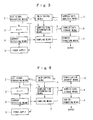
- FIG. 7 is a drawing showing the configuration of the seventh embodiment.
- the seventh embodiment in comparison to the fifth embodiment, has a sampled data analysis means 11 in place of the Fourier transform window information storage means 13 , and has the addition of a Fourier transform window determining means 14 .
- the sampled data analysis means 11 analyzes the sampled power supply current data by the sampling means 7 , and determines the amount of time extension that should be made to the sampling of the power supply current value signal to obtain accurate power supply current information.
- the thus determined sampling extension time is send to the Fourier transform window determining means 14 , which issues an instruction to the Fourier transform means 9 with regard to a sampling range (window) to be subjected to a Fourier transformation, in correspondence to this extension time.
- FIG. 17 is a flowchart showing the operation of the seventh embodiment.
- the steps S 701 to S 708 and S 711 to S 712 are the same as steps S 501 to S 508 , S 510 , and S 511 in the fifth embodiment, and are thus not described herein.
- sampled data analysis means 11 a check is made of the sampled data for the power supply current value signal stored in the sampled data storage means 8 , and a judgment is made with regard to how much time after the end of application of the test signal to the DUT 3 the sampling should be continued in order to obtain accurate power supply current information, this range being sent to the Fourier transform window determining means 14 (step S 709 in FIG. 17 ).
- the Fourier transform window determining means 14 determines, of the sampled data of the power supply current value signal, the range of sampled data to be subjected to a Fourier transformation, and sends that data range to the Fourier transform means 9 (step S 710 in FIG. 17 ).
- This series of operations can be coded as a control program of the related control operations, which is executed by the main control means 1 , thereby controlling the operation of various sections of the apparatus.
- the control program is stored into a storage medium (not shown in the drawing) such as a ROM or floppy disk attached to the main control means 1 , this program being then loaded into the main control means.
- the operational effect of the seventh embodiment of the present invention includes the effect of the third embodiment and the effect of the fifth embodiment of the present invention.
- FIG. 8 is a drawing showing the configuration of the eighth embodiment.
- the eighth embodiment in comparison with the seventh embodiment, has a stabilization judgment means 12 in place of the sampled data analysis means 11 .
- the stabilization judgment means 12 a check is made as to how much time after the end of application of the test signal to the DUT 3 is required for the power supply current to either stop or stabilize, this time being calculated. The result is sent to the Fourier transform window determining means 14 .
- FIG. 18 is a flowchart showing the operation of the eighth embodiment of the present invention.
- the steps S 801 to S 808 and S 810 to S 812 are the same as steps S 701 to S 708 and S 710 to S 712 in the seventh embodiment, and are thus not described herein.
- the sampled data storage means 8 is accessed, the sampled power supply current value signal sampled by the sampling means 7 is received, and an analysis is performed. What is analyzed is how much time after the end of application of the test signal to the DUT 3 is required for the power supply current detected by the current detection means 4 to either stop or stabilize, this time being calculated. This result is sent to the Fourier transform window determining means 14 (step S 809 in FIG. 18 ).
- This series of operations can be coded as a control program of the related control operations, which is executed by the main control means 1 , thereby controlling the operation of various sections of the apparatus.
- the control program is stored into a storage medium (not shown in the drawing) such as a ROM or floppy disk attached to the main control means 1 , this program being then loaded into the main control means.
- the effect of the eighth embodiment of the present invention is the combination of the effects of the fourth embodiment and the fifth embodiment of the present invention.
- the present invention by obtaining and analyzing the power supply current information after the end of application of the test signal to the DUT 3 for a pre-established amount of time, an amount of time responsive to the time constant of the circuitry, or an amount of time obtained by an actual measurement of the power supply current, it is possible to obtain more accurate power supply current information.
Abstract
Description
Claims (29)
Priority Applications (1)
| Application Number | Priority Date | Filing Date | Title |
|---|---|---|---|
| US11/215,012 US7483799B2 (en) | 2000-03-03 | 2005-08-31 | Method and apparatus for sampling a power supply current of an integrated circuit, and storage medium onto which is recorded a control program therefor |
Applications Claiming Priority (2)
| Application Number | Priority Date | Filing Date | Title |
|---|---|---|---|
| JP2000059090A JP3389914B2 (en) | 2000-03-03 | 2000-03-03 | Sampling method and device for power supply current value of integrated circuit, and storage medium storing control program therefor |
| JP2000-59090 | 2000-03-03 |
Related Child Applications (1)
| Application Number | Title | Priority Date | Filing Date |
|---|---|---|---|
| US11/215,012 Division US7483799B2 (en) | 2000-03-03 | 2005-08-31 | Method and apparatus for sampling a power supply current of an integrated circuit, and storage medium onto which is recorded a control program therefor |
Publications (2)
| Publication Number | Publication Date |
|---|---|
| US20010020283A1 US20010020283A1 (en) | 2001-09-06 |
| US6996489B2 true US6996489B2 (en) | 2006-02-07 |
Family
ID=18579591
Family Applications (2)
| Application Number | Title | Priority Date | Filing Date |
|---|---|---|---|
| US09/796,451 Expired - Lifetime US6996489B2 (en) | 2000-03-03 | 2001-03-02 | Method and apparatus for sampling a power supply current of an integrated circuit, and storage medium onto which is recorded a control program therefor |
| US11/215,012 Expired - Lifetime US7483799B2 (en) | 2000-03-03 | 2005-08-31 | Method and apparatus for sampling a power supply current of an integrated circuit, and storage medium onto which is recorded a control program therefor |
Family Applications After (1)
| Application Number | Title | Priority Date | Filing Date |
|---|---|---|---|
| US11/215,012 Expired - Lifetime US7483799B2 (en) | 2000-03-03 | 2005-08-31 | Method and apparatus for sampling a power supply current of an integrated circuit, and storage medium onto which is recorded a control program therefor |
Country Status (2)
| Country | Link |
|---|---|
| US (2) | US6996489B2 (en) |
| JP (1) | JP3389914B2 (en) |
Cited By (5)
| Publication number | Priority date | Publication date | Assignee | Title |
|---|---|---|---|---|
| US20020049646A1 (en) * | 2000-10-24 | 2002-04-25 | Michiaki Yokoyama | Method of and apparatus for acquiring new customers, and computer product |
| US20060007226A1 (en) * | 2000-03-03 | 2006-01-12 | Nec Corporation | Method and apparatus for sampling a power supply current of an integrated circuit, and storage medium onto which is recorded a control program therefor |
| US20060235648A1 (en) * | 2003-07-15 | 2006-10-19 | Zheltov Sergey N | Method of efficient performance monitoring for symetric multi-threading systems |
| US20080129481A1 (en) * | 2006-12-04 | 2008-06-05 | Michael Lynn Zumbrunnen | Method and Apparatus for Enhancing Motor Vehicle Turn Signal Awareness |
| US20080297121A1 (en) * | 2007-06-01 | 2008-12-04 | Advantest Corporation | Power supply apparatus, test apparatus, and electronic device |
Families Citing this family (26)
| Publication number | Priority date | Publication date | Assignee | Title |
|---|---|---|---|---|
| US5914613A (en) | 1996-08-08 | 1999-06-22 | Cascade Microtech, Inc. | Membrane probing system with local contact scrub |
| US6256882B1 (en) | 1998-07-14 | 2001-07-10 | Cascade Microtech, Inc. | Membrane probing system |
| US6445202B1 (en) | 1999-06-30 | 2002-09-03 | Cascade Microtech, Inc. | Probe station thermal chuck with shielding for capacitive current |
| US6914423B2 (en) | 2000-09-05 | 2005-07-05 | Cascade Microtech, Inc. | Probe station |
| US6965226B2 (en) | 2000-09-05 | 2005-11-15 | Cascade Microtech, Inc. | Chuck for holding a device under test |
| DE10143173A1 (en) | 2000-12-04 | 2002-06-06 | Cascade Microtech Inc | Wafer probe has contact finger array with impedance matching network suitable for wide band |
| US7114098B2 (en) * | 2001-03-20 | 2006-09-26 | American Power Conversion Corporation | Power supply critical state monitoring system |
| AU2002327490A1 (en) | 2001-08-21 | 2003-06-30 | Cascade Microtech, Inc. | Membrane probing system |
| US7492172B2 (en) | 2003-05-23 | 2009-02-17 | Cascade Microtech, Inc. | Chuck for holding a device under test |
| US7057404B2 (en) | 2003-05-23 | 2006-06-06 | Sharp Laboratories Of America, Inc. | Shielded probe for testing a device under test |
| US7250626B2 (en) | 2003-10-22 | 2007-07-31 | Cascade Microtech, Inc. | Probe testing structure |
| US7427868B2 (en) | 2003-12-24 | 2008-09-23 | Cascade Microtech, Inc. | Active wafer probe |
| US7187188B2 (en) | 2003-12-24 | 2007-03-06 | Cascade Microtech, Inc. | Chuck with integrated wafer support |
| KR100768913B1 (en) * | 2004-08-04 | 2007-10-19 | 삼성전자주식회사 | Host apparatus sensing the strange signal of external device connected by communication cable and method thereof |
| US7420381B2 (en) | 2004-09-13 | 2008-09-02 | Cascade Microtech, Inc. | Double sided probing structures |
| US7535247B2 (en) | 2005-01-31 | 2009-05-19 | Cascade Microtech, Inc. | Interface for testing semiconductors |
| US7656172B2 (en) | 2005-01-31 | 2010-02-02 | Cascade Microtech, Inc. | System for testing semiconductors |
| US7723999B2 (en) | 2006-06-12 | 2010-05-25 | Cascade Microtech, Inc. | Calibration structures for differential signal probing |
| US7764072B2 (en) | 2006-06-12 | 2010-07-27 | Cascade Microtech, Inc. | Differential signal probing system |
| US7403028B2 (en) | 2006-06-12 | 2008-07-22 | Cascade Microtech, Inc. | Test structure and probe for differential signals |
| US7876114B2 (en) | 2007-08-08 | 2011-01-25 | Cascade Microtech, Inc. | Differential waveguide probe |
| JP5446112B2 (en) * | 2008-03-31 | 2014-03-19 | 富士通セミコンダクター株式会社 | Semiconductor device and method for monitoring operation of semiconductor device |
| US7888957B2 (en) | 2008-10-06 | 2011-02-15 | Cascade Microtech, Inc. | Probing apparatus with impedance optimized interface |
| US8410806B2 (en) | 2008-11-21 | 2013-04-02 | Cascade Microtech, Inc. | Replaceable coupon for a probing apparatus |
| US8319503B2 (en) | 2008-11-24 | 2012-11-27 | Cascade Microtech, Inc. | Test apparatus for measuring a characteristic of a device under test |
| US9052901B2 (en) | 2011-12-14 | 2015-06-09 | Intel Corporation | Method, apparatus, and system for energy efficiency and energy conservation including configurable maximum processor current |
Citations (12)
| Publication number | Priority date | Publication date | Assignee | Title |
|---|---|---|---|---|
| JPH05315424A (en) | 1992-01-29 | 1993-11-26 | Advanced Micro Devices Inc | Radiant-ray microscope software and method for inspection of integrated circuit by using it |
| JPH07280880A (en) | 1994-04-04 | 1995-10-27 | Advantest Corp | Stationary power supply current tester for ic |
| US5629870A (en) * | 1994-05-31 | 1997-05-13 | Siemens Energy & Automation, Inc. | Method and apparatus for predicting electric induction machine failure during operation |
| JP2734416B2 (en) | 1995-07-24 | 1998-03-30 | 日本電気株式会社 | Method and apparatus for identifying failure mode |
| US5784233A (en) * | 1994-01-06 | 1998-07-21 | Schneider Electric Sa | Differential protection device of a power transformer |
| JP2783243B2 (en) | 1996-02-06 | 1998-08-06 | 日本電気株式会社 | Method and apparatus for detecting failure of CMOS integrated circuit |
| JPH11142468A (en) | 1997-09-03 | 1999-05-28 | Nec Corp | Device and method for detecting fault of integrated circuit and recording medium in which detected control program is recorded |
| JP2962283B2 (en) | 1997-06-12 | 1999-10-12 | 日本電気株式会社 | Fault detection method and fault detection device for integrated circuit |
| JP2000046899A (en) | 1998-07-31 | 2000-02-18 | Nec Corp | Method and system for observing spectrum of power supply current |
| US6351835B1 (en) | 1998-07-31 | 2002-02-26 | Nec Corporation | High speed LSI spectral analysis testing apparatus and method |
| US20040051549A1 (en) * | 1999-01-13 | 2004-03-18 | Fujitsu Limited | Semiconductor device, method of testing the semiconductor device, and semiconductor integrated circuit |
| US6766485B1 (en) * | 1999-09-27 | 2004-07-20 | Nec Electronics Corporation | Integrated circuit fault tester, integrated circuit fault test method and recording medium recorded with fault test control program |
Family Cites Families (2)
| Publication number | Priority date | Publication date | Assignee | Title |
|---|---|---|---|---|
| JPH11142416A (en) * | 1997-11-12 | 1999-05-28 | Olympus Optical Co Ltd | Correction method of data measured by scanning probe microscope |
| JP3389914B2 (en) * | 2000-03-03 | 2003-03-24 | 日本電気株式会社 | Sampling method and device for power supply current value of integrated circuit, and storage medium storing control program therefor |
-
2000
- 2000-03-03 JP JP2000059090A patent/JP3389914B2/en not_active Expired - Lifetime
-
2001
- 2001-03-02 US US09/796,451 patent/US6996489B2/en not_active Expired - Lifetime
-
2005
- 2005-08-31 US US11/215,012 patent/US7483799B2/en not_active Expired - Lifetime
Patent Citations (13)
| Publication number | Priority date | Publication date | Assignee | Title |
|---|---|---|---|---|
| JPH05315424A (en) | 1992-01-29 | 1993-11-26 | Advanced Micro Devices Inc | Radiant-ray microscope software and method for inspection of integrated circuit by using it |
| US5661520A (en) | 1992-01-29 | 1997-08-26 | Bruce; Victoria Jean | Energy resolved emission microscopy system and method |
| US5784233A (en) * | 1994-01-06 | 1998-07-21 | Schneider Electric Sa | Differential protection device of a power transformer |
| JPH07280880A (en) | 1994-04-04 | 1995-10-27 | Advantest Corp | Stationary power supply current tester for ic |
| US5629870A (en) * | 1994-05-31 | 1997-05-13 | Siemens Energy & Automation, Inc. | Method and apparatus for predicting electric induction machine failure during operation |
| JP2734416B2 (en) | 1995-07-24 | 1998-03-30 | 日本電気株式会社 | Method and apparatus for identifying failure mode |
| JP2783243B2 (en) | 1996-02-06 | 1998-08-06 | 日本電気株式会社 | Method and apparatus for detecting failure of CMOS integrated circuit |
| JP2962283B2 (en) | 1997-06-12 | 1999-10-12 | 日本電気株式会社 | Fault detection method and fault detection device for integrated circuit |
| JPH11142468A (en) | 1997-09-03 | 1999-05-28 | Nec Corp | Device and method for detecting fault of integrated circuit and recording medium in which detected control program is recorded |
| JP2000046899A (en) | 1998-07-31 | 2000-02-18 | Nec Corp | Method and system for observing spectrum of power supply current |
| US6351835B1 (en) | 1998-07-31 | 2002-02-26 | Nec Corporation | High speed LSI spectral analysis testing apparatus and method |
| US20040051549A1 (en) * | 1999-01-13 | 2004-03-18 | Fujitsu Limited | Semiconductor device, method of testing the semiconductor device, and semiconductor integrated circuit |
| US6766485B1 (en) * | 1999-09-27 | 2004-07-20 | Nec Electronics Corporation | Integrated circuit fault tester, integrated circuit fault test method and recording medium recorded with fault test control program |
Non-Patent Citations (2)
| Title |
|---|
| "Microsoft Press Computer Dictionary, Second Edition", 1993, Microsoft Press, p. 174. * |
| Sakaguchi, K. et al., "Fast Fault Detection by Analyzing the Power Spectrum of Supply Current" SEMI Technology Symposium 98:3-77 to 3-83. |
Cited By (8)
| Publication number | Priority date | Publication date | Assignee | Title |
|---|---|---|---|---|
| US20060007226A1 (en) * | 2000-03-03 | 2006-01-12 | Nec Corporation | Method and apparatus for sampling a power supply current of an integrated circuit, and storage medium onto which is recorded a control program therefor |
| US7483799B2 (en) * | 2000-03-03 | 2009-01-27 | Nec Corporation | Method and apparatus for sampling a power supply current of an integrated circuit, and storage medium onto which is recorded a control program therefor |
| US20020049646A1 (en) * | 2000-10-24 | 2002-04-25 | Michiaki Yokoyama | Method of and apparatus for acquiring new customers, and computer product |
| US20060235648A1 (en) * | 2003-07-15 | 2006-10-19 | Zheltov Sergey N | Method of efficient performance monitoring for symetric multi-threading systems |
| US7836447B2 (en) * | 2003-07-15 | 2010-11-16 | Intel Corporation | Method of efficient performance monitoring for symmetric multi-threading systems |
| US20080129481A1 (en) * | 2006-12-04 | 2008-06-05 | Michael Lynn Zumbrunnen | Method and Apparatus for Enhancing Motor Vehicle Turn Signal Awareness |
| US20080297121A1 (en) * | 2007-06-01 | 2008-12-04 | Advantest Corporation | Power supply apparatus, test apparatus, and electronic device |
| US7969124B2 (en) * | 2007-06-01 | 2011-06-28 | Advantest Corporation | Power supply apparatus, test apparatus, and electronic device |
Also Published As
| Publication number | Publication date |
|---|---|
| JP3389914B2 (en) | 2003-03-24 |
| US20010020283A1 (en) | 2001-09-06 |
| US7483799B2 (en) | 2009-01-27 |
| US20060007226A1 (en) | 2006-01-12 |
| JP2001249158A (en) | 2001-09-14 |
Similar Documents
| Publication | Publication Date | Title |
|---|---|---|
| US7483799B2 (en) | Method and apparatus for sampling a power supply current of an integrated circuit, and storage medium onto which is recorded a control program therefor | |
| KR100249252B1 (en) | System for detecting troubles in cmos integrated circuit | |
| JP2002506975A (en) | Simultaneous display of primary measurement values and acquisition parameters | |
| US5789933A (en) | Method and apparatus for determining IDDQ | |
| CN108571997B (en) | Method and device for detecting stable contact of probe with measured point | |
| CN112821885A (en) | Relative time delay measurement calibration method and device for chips of each channel of ATE (automatic test equipment) | |
| US20090273350A1 (en) | Systems and Methods for Detecting Wire Breaks | |
| US6766485B1 (en) | Integrated circuit fault tester, integrated circuit fault test method and recording medium recorded with fault test control program | |
| JP2006500559A (en) | IDDQ determination method and apparatus | |
| US6577150B1 (en) | Testing apparatus and method of measuring operation timing of semiconductor device | |
| JP4970640B2 (en) | Screening method, screening apparatus and recording medium | |
| US6704675B1 (en) | Method of detecting an integrated circuit in failure among integrated circuits, apparatus of doing the same, and recording medium storing program for doing the same | |
| US20020099993A1 (en) | Semiconductor testing apparatus and method | |
| CN106840246A (en) | A kind of vibrating string type sensor work condition on-line testing method and device | |
| US6891361B2 (en) | Automatic gain control (AGC) loop for characterizing continuous-time or discrete-time circuitry gain response across frequency | |
| JP3085284B2 (en) | Method and apparatus for observing power supply current spectrum | |
| JP5150386B2 (en) | Electromagnetic noise diagnostic device, electromagnetic noise diagnostic system, and electromagnetic noise diagnostic method | |
| KR20200103994A (en) | Calibration Method to Input Constant Pressure to Pressure Sensor Test Board using Automatic Test Equipment | |
| JP2003161766A (en) | Apparatus for testing semiconductor integrated circuit | |
| US6445207B1 (en) | IC tester and IC test method | |
| CN115932552A (en) | Current characteristic verification method, apparatus, and medium | |
| JP2002214281A (en) | Integrated circuit testing device and method and recording medium recording control program describing testing method | |
| CN117256967A (en) | Method, device, equipment and storage medium for detecting starting threshold of airflow sensor | |
| RU2125287C1 (en) | Method for calculation of transfer function weights for non-linear dynamic objects | |
| JP2004085469A (en) | Semiconductor device inspection method and system |
Legal Events
| Date | Code | Title | Description |
|---|---|---|---|
| AS | Assignment |
Owner name: NEC CORPORATION, JAPAN Free format text: ASSIGNMENT OF ASSIGNORS INTEREST;ASSIGNOR:SAKAGUCHI, KAZUHIRO;REEL/FRAME:011580/0006 Effective date: 20010115 |
|
| AS | Assignment |
Owner name: NEC ELECTRONICS CORPORATION, JAPAN Free format text: ASSIGNMENT OF ASSIGNORS INTEREST;ASSIGNOR:NEC CORPORATION;REEL/FRAME:014922/0541 Effective date: 20040105 |
|
| FEPP | Fee payment procedure |
Free format text: PAYOR NUMBER ASSIGNED (ORIGINAL EVENT CODE: ASPN); ENTITY STATUS OF PATENT OWNER: LARGE ENTITY |
|
| STCF | Information on status: patent grant |
Free format text: PATENTED CASE |
|
| FPAY | Fee payment |
Year of fee payment: 4 |
|
| AS | Assignment |
Owner name: RENESAS ELECTRONICS CORPORATION, JAPAN Free format text: CHANGE OF NAME;ASSIGNOR:NEC ELECTRONICS CORPORATION;REEL/FRAME:025375/0918 Effective date: 20100401 |
|
| FPAY | Fee payment |
Year of fee payment: 8 |
|
| AS | Assignment |
Owner name: RENESAS ELECTRONICS CORPORATION, JAPAN Free format text: ASSIGNMENT OF ASSIGNORS INTEREST;ASSIGNOR:NEC CORPORATION;REEL/FRAME:039254/0802 Effective date: 20160713 |
|
| FPAY | Fee payment |
Year of fee payment: 12 |
|
| AS | Assignment |
Owner name: RENESAS ELECTRONICS CORPORATION, JAPAN Free format text: CHANGE OF ADDRESS;ASSIGNOR:RENESAS ELECTRONICS CORPORATION;REEL/FRAME:044928/0001 Effective date: 20150806 |