US6997328B2 - Grit removal assemblies - Google Patents
Grit removal assemblies Download PDFInfo
- Publication number
- US6997328B2 US6997328B2 US10/640,420 US64042003A US6997328B2 US 6997328 B2 US6997328 B2 US 6997328B2 US 64042003 A US64042003 A US 64042003A US 6997328 B2 US6997328 B2 US 6997328B2
- Authority
- US
- United States
- Prior art keywords
- tank
- fluid
- assembly
- flow
- inlet
- Prior art date
- Legal status (The legal status is an assumption and is not a legal conclusion. Google has not performed a legal analysis and makes no representation as to the accuracy of the status listed.)
- Expired - Lifetime
Links
Images


Classifications
-
- B—PERFORMING OPERATIONS; TRANSPORTING
- B01—PHYSICAL OR CHEMICAL PROCESSES OR APPARATUS IN GENERAL
- B01D—SEPARATION
- B01D21/00—Separation of suspended solid particles from liquids by sedimentation
- B01D21/0012—Settling tanks making use of filters, e.g. by floating layers of particulate material
-
- B—PERFORMING OPERATIONS; TRANSPORTING
- B01—PHYSICAL OR CHEMICAL PROCESSES OR APPARATUS IN GENERAL
- B01D—SEPARATION
- B01D21/00—Separation of suspended solid particles from liquids by sedimentation
- B01D21/0039—Settling tanks provided with contact surfaces, e.g. baffles, particles
-
- B—PERFORMING OPERATIONS; TRANSPORTING
- B01—PHYSICAL OR CHEMICAL PROCESSES OR APPARATUS IN GENERAL
- B01D—SEPARATION
- B01D21/00—Separation of suspended solid particles from liquids by sedimentation
- B01D21/0039—Settling tanks provided with contact surfaces, e.g. baffles, particles
- B01D21/0042—Baffles or guide plates
-
- B—PERFORMING OPERATIONS; TRANSPORTING
- B01—PHYSICAL OR CHEMICAL PROCESSES OR APPARATUS IN GENERAL
- B01D—SEPARATION
- B01D21/00—Separation of suspended solid particles from liquids by sedimentation
- B01D21/24—Feed or discharge mechanisms for settling tanks
- B01D21/2405—Feed mechanisms for settling tanks
-
- B—PERFORMING OPERATIONS; TRANSPORTING
- B01—PHYSICAL OR CHEMICAL PROCESSES OR APPARATUS IN GENERAL
- B01D—SEPARATION
- B01D21/00—Separation of suspended solid particles from liquids by sedimentation
- B01D21/24—Feed or discharge mechanisms for settling tanks
- B01D21/245—Discharge mechanisms for the sediments
- B01D21/2461—Positive-displacement pumps; Screw feeders; Trough conveyors
Definitions
- a screw is utilized to convey solids to a discharge point, and to agitate the fluidized bed of materials, releasing entrapped slimes for removal. Sizing of the screws and speeds utilized are dependent upon expected volumes of grit and capacity output as required by the application. Variable speed drive units are commonly utilized. Both designs targeted removing 95% of the grit contained within the slurry. Traditionally, these units only run about 15–20 minutes every 3 to 4 hours, with timing based upon how often the upstream process equipment flowing into the unit was set or required to run.
- Vortex grit separation has now moved into becoming the more commonly utilized first stage method to handle larger flows and smaller grit particles and is run generally on a continuous basis during storm events. What this has also done is to begin replacing the previously popular and commonly used grit cyclones as the first stage separator of the grit slurry.
- the Vortex systems typically preferred in CSO applications do not have many of the problems associated with cyclones, such as routine plugging and rapid wear of the underflow (apex) end of the cyclone.
- the present invention provides an assembly for removing grit from a fluid.
- the assembly comprises a tank with a fluid inlet into the tank and a discharge from the tank.
- a flow directing assembly is positioned in the tank adjacent the fluid inlet.
- the flow directing assembly includes a substantially U-shaped surface opposite the fluid inlet such that fluid entering the tank through the inlet is caused to have a reversed flow in a direction more than 90 degrees from an inlet flow direction.
- At least one embodiment of the assembly further comprises a baffle positioned proximate the tank discharge to control flow adjacent the discharge.
- Yet a further embodiment of the assembly includes a screw conveyor positioned in a trough of the tank and a baffle is positioned proximate the trough to minimize fluid flow velocity adjacent to the screw conveyor.
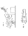
- FIGS. 1–3 are side, top and rear, respectively, plan views of an illustrative grit washer tank assembly useable with the present invention
- FIGS. 4 and 5 are side and top, respectively, plan views of an illustrative grit classifier tank assembly useable with the present invention
- FIGS. 6 and 7 are top and side, respectively, plan views of an a first embodiment of the present invention utilized with a grit washer tank assembly;
- FIG. 8 is a front plan view of a plate that is part of the present embodiment of the present invention.
- FIGS. 11 and 12 are surface and end, respectively, plan views of another plate of the present embodiment of the present invention.
- FIGS. 16 and 17 are surface and end, respectively, plan views of a discharge baffle of the present embodiment of the present invention.
- FIG. 18 is an end plan view of the flow directing assembly of the present embodiment of the present invention.
- the grit washer tank assembly 10 includes inwardly sloped side walls 14 , 16 and an inwardly sloped rear wall 18 .
- the side walls 14 , 16 and the rear wall 18 are joined by a trough 20 extending from the rear wall 18 along the length of and beyond the side walls 14 , 16 .
- the trough 20 is configured to support a screw conveyor 22 therein.
- the screw conveyor 22 is driven by a motor 24 or other drive to move material along the trough 20 and out a discharge 26 near the forward end of the trough 20 .
- the discharge 26 is aligned with a disposal mechanism (not shown), for example, a bin or a conveyor, to remove and dispose of the discharged material.
- the preferred flow directing assembly 60 includes a plurality of plates positioned within the tank to direct flow of the fluid within the tank 12 .
- several of the plates are interconnected, and may be formed as individual components connected to one another, for example, via bolting, welding or the like, or may be formed from a single sheet bent or otherwise contoured to define the various plates, or a combination of both.
- a plate 62 extends between the side walls 14 and 16 and provides a solid surface substantially parallel to the inlet pipe 30 .
- Plate 62 extends from above the pipe outlet 32 to below the pipe outlet 32 , thereby preventing direct horizontal, rearward flow from the pipe outlet 32 .
- portions 66 , 68 , 73 and 74 which are all solid as illustrated by the thick solid line in FIG. 18 , define a substantially U-shaped solid surface into which flow from the pipe outlet 32 is directed. Flow into the U-shaped solid surface causes the fluid to be rapidly redirected upward and outward, causing a rolling action in the fluid, with the majority of the fluid being forced to flow toward the rear, larger portion of the tank 12 .
- Plate 76 extends from rearward plate 70 , with an upper solid portion 78 and a downward extending portion 80 .
- the solid upper portion 78 helps to maintain the rolling flow in the upper portion of the tank 12 for a longer period.
- the configuration of the discharge baffle 82 is selected to control the flow velocity to the discharge pipes 40 , 42 .
- the flow velocity at the discharge pipes 40 , 42 is preferably greater than the flow velocity in the quiescent zone 95 of the tank 12 , as will be described hereinafter.
- the forced flow patterns and rolling action caused by the flow directing assembly 60 causes the inlet flow momentum to disperse rapidly.
- the flow directing assembly 60 , the plates with through holes 65 , 67 , 69 , 91 and the baffle plate 90 , positioned properly in the tank provides a quiescent zone 95 with flow velocities within established target ranges which allows settling of finer mesh materials to take place in the bottom rear of the tank. Additionally, the target velocities allow the screw conveyor 22 to remove the settled grit particles without disruption caused by high velocity or turbulence in the screw conveyor removal zone.
- the target velocity for removing 100 mesh particles is 0.35 ft/sec while the target velocity for removing 150 mesh particles is 0.25 ft/sec.
- the flow directing assembly 60 , the plates with through holes 65 , 67 , 69 , 91 and the baffle plate 90 allow the target velocities to be achieved to allow desired separation without the washer assembly 10 being dependent upon large surface areas to diffuse the inlet velocity.
- the flow directing assembly 60 creates the desired flow pattern with the desired flow velocities.
- a tank 12 with a sufficient depth will provide the appropriate quiescent zone 95 to allow separation at the slower flow velocities.
- a tank 12 including a flow directing assembly 60 and having a rear depth of 48 inches has been found sufficient to separate 100 mesh material at 200 GPM.
- the flow directing assembly 60 and baffles allow separation to be achieved while utilizing smaller tank volumes.
- a tank including a flow directing assembly 60 and a volume of 160 gallons has been found sufficient to separate 100 mesh material at 200 GPM.
- the depths and volumes are for example purposes only and may be adjusted based on numerous variables, including particle size and flow rates.
- the present invention includes a flow directing assembly 100 positioned adjacent the inlet pipe outlet 32 and a screw conveyor baffle plate 116 positioned above the screw conveyor 22 .
- a weir plate 52 is positioned adjacent to the discharge box 54 and the inlet pipe outlet 32 is below the water level WL.
- the inlet pipe 30 is forward of center, front to rear. Such positioning is forward the typical inlet position of prior art classifier assemblies, and has been found to be more effective at providing a controlled flow within the tank 12 .
- the flow directing assembly 100 includes opposed solid plates 102 and 104 extending parallel to and on opposite sides of the inlet pipe 30 .
- the plates 102 and 104 extend between the side walls 14 , 16 of the tank 12 and prevent fluid flow directly forward or rearward.
- An angled plate portion 114 extends from plate 104 and extends opposite from the pipe outlet 32 .
- the solid portions 102 , 104 and 114 define a substantially U-shaped solid surface into which flow from the pipe outlet 32 is directed. Flow into the U-shaped solid surface causes the fluid to be rapidly redirected upward and outward, causing a rolling action in the fluid, with the majority of the fluid being forced to flow toward the rear, larger portion of the tank 12 .
Abstract
Description
Claims (14)
Priority Applications (1)
| Application Number | Priority Date | Filing Date | Title |
|---|---|---|---|
| US10/640,420 US6997328B2 (en) | 2003-08-13 | 2003-08-13 | Grit removal assemblies |
Applications Claiming Priority (1)
| Application Number | Priority Date | Filing Date | Title |
|---|---|---|---|
| US10/640,420 US6997328B2 (en) | 2003-08-13 | 2003-08-13 | Grit removal assemblies |
Publications (2)
| Publication Number | Publication Date |
|---|---|
| US20050035056A1 US20050035056A1 (en) | 2005-02-17 |
| US6997328B2 true US6997328B2 (en) | 2006-02-14 |
Family
ID=34136085
Family Applications (1)
| Application Number | Title | Priority Date | Filing Date |
|---|---|---|---|
| US10/640,420 Expired - Lifetime US6997328B2 (en) | 2003-08-13 | 2003-08-13 | Grit removal assemblies |
Country Status (1)
| Country | Link |
|---|---|
| US (1) | US6997328B2 (en) |
Cited By (8)
| Publication number | Priority date | Publication date | Assignee | Title |
|---|---|---|---|---|
| US20060065610A1 (en) * | 2004-09-28 | 2006-03-30 | Spx Corporation | Trapezoid settler apparatus and method for solvent extraction |
| US20060096935A1 (en) * | 2004-11-08 | 2006-05-11 | Harding Darin M | Method and apparatus for removing cuttings from drilling fluids |
| US20070125545A1 (en) * | 2004-11-08 | 2007-06-07 | Harding Darin M | Method and apparatus for removing cuttings from drilling fluids |
| US20090095672A1 (en) * | 2007-10-10 | 2009-04-16 | Wilcher Stephen B | High efficiency grit removal system |
| US8017021B1 (en) * | 2006-02-01 | 2011-09-13 | Staples Wesley A | Sludge processing apparatus and method |
| US8622225B2 (en) | 2006-05-02 | 2014-01-07 | Brien Edward Goninan | Fluid purification using hydraulic vortex system |
| ITUB20152224A1 (en) * | 2015-07-16 | 2017-01-16 | Giampietro Verza | MACHINE FOR THE PRIMARY TREATMENT OF URBAN AND INDUSTRIAL WASTE |
| US11389992B1 (en) | 2021-10-20 | 2022-07-19 | Olivier Hugo Christopher Dany Vanderbeken | Small footprint pre-treatment plant and decentralized food waste separation and treatment |
Families Citing this family (2)
| Publication number | Priority date | Publication date | Assignee | Title |
|---|---|---|---|---|
| DE102004058421A1 (en) * | 2004-10-01 | 2006-04-13 | Hans Huber Ag Maschinen- Und Anlagenbau | Plant for the mechanical cleaning of liquids and process for the separation of suspended matter |
| US11319247B2 (en) * | 2019-10-21 | 2022-05-03 | Rdp Technologies, Inc. | Fine grit classifier |
Citations (24)
| Publication number | Priority date | Publication date | Assignee | Title |
|---|---|---|---|---|
| US545026A (en) * | 1895-08-20 | Sand and air separator for artesian or driven wells | ||
| US1762593A (en) | 1927-11-15 | 1930-06-10 | Henry G Schwarz | Separator |
| US2118157A (en) * | 1934-12-24 | 1938-05-24 | Jeffrey Mfg Co | Apparatus for purifying liquids |
| US3933654A (en) * | 1972-06-21 | 1976-01-20 | Frederic R. Harris (Holland) B.V. | Oil separator for separating oil lighter than the purified liquid being in a very pure state |
| US4042512A (en) * | 1976-10-27 | 1977-08-16 | Mccarthy Patrick M | Oil water separator |
| US4064054A (en) * | 1976-12-22 | 1977-12-20 | Chevron Research Company | Apparatus for separating oil-water mixtures |
| US4072614A (en) | 1975-02-21 | 1978-02-07 | Harris Frank N | Oil and water separators |
| US4351733A (en) * | 1980-11-15 | 1982-09-28 | Robert Bosch Gmbh | Process and apparatus for purification of industrial waste water |
| US4422931A (en) * | 1982-04-15 | 1983-12-27 | Wolde Michael Girma | Oil concentrator |
| US4722800A (en) * | 1986-05-30 | 1988-02-02 | Highland Tank And Manufacturing Company | Oil-water separator |
| US4871449A (en) | 1988-06-27 | 1989-10-03 | Lott W Gerald | Clarifier and screw compactor liquid-solid separator |
| US4886605A (en) * | 1986-03-25 | 1989-12-12 | Eparco | All-purpose septic tank |
| US5021153A (en) | 1989-11-20 | 1991-06-04 | G-H Systems, Inc. | Combined apparatus for removing grit and grease from sewage |
| US5326474A (en) | 1992-11-13 | 1994-07-05 | The United States Of America As Represented By The Secretary Of The Navy | Low flow fluid separator |
| US5378375A (en) | 1992-02-15 | 1995-01-03 | Jones & Attwood Limited | Apparatus and method of washing screenings |
| US5505860A (en) * | 1994-10-24 | 1996-04-09 | Sager; Robert J. | Grease and oil trap |
| US5520825A (en) * | 1993-11-08 | 1996-05-28 | Mctighe Industries, Inc. | Oil-water separator |
| US5605636A (en) * | 1995-04-20 | 1997-02-25 | Mcnish Corporation | Liquid clarification device and method |
| US5643443A (en) | 1995-05-19 | 1997-07-01 | Taiki Corporation, U.S.A. | Water purification system |
| US5714069A (en) | 1996-09-25 | 1998-02-03 | Sager; Robert | Apparatus for removing grease from waste water |
| US6120684A (en) | 1998-01-06 | 2000-09-19 | Tec-Kon Enterprises, Llc | Stormwater treatment system |
| US20010027954A1 (en) * | 2000-02-23 | 2001-10-11 | Canplas Industries Ltd. | Wastewater separator and method of using same |
| US6350374B1 (en) | 2000-01-19 | 2002-02-26 | Jensen Enterprises, Inc. | Stormwater treatment apparatus |
| US6395181B1 (en) | 2000-10-04 | 2002-05-28 | Great Circle Technologies, Inc. | Process and apparatus for treating wastewater |
-
2003
- 2003-08-13 US US10/640,420 patent/US6997328B2/en not_active Expired - Lifetime
Patent Citations (24)
| Publication number | Priority date | Publication date | Assignee | Title |
|---|---|---|---|---|
| US545026A (en) * | 1895-08-20 | Sand and air separator for artesian or driven wells | ||
| US1762593A (en) | 1927-11-15 | 1930-06-10 | Henry G Schwarz | Separator |
| US2118157A (en) * | 1934-12-24 | 1938-05-24 | Jeffrey Mfg Co | Apparatus for purifying liquids |
| US3933654A (en) * | 1972-06-21 | 1976-01-20 | Frederic R. Harris (Holland) B.V. | Oil separator for separating oil lighter than the purified liquid being in a very pure state |
| US4072614A (en) | 1975-02-21 | 1978-02-07 | Harris Frank N | Oil and water separators |
| US4042512A (en) * | 1976-10-27 | 1977-08-16 | Mccarthy Patrick M | Oil water separator |
| US4064054A (en) * | 1976-12-22 | 1977-12-20 | Chevron Research Company | Apparatus for separating oil-water mixtures |
| US4351733A (en) * | 1980-11-15 | 1982-09-28 | Robert Bosch Gmbh | Process and apparatus for purification of industrial waste water |
| US4422931A (en) * | 1982-04-15 | 1983-12-27 | Wolde Michael Girma | Oil concentrator |
| US4886605A (en) * | 1986-03-25 | 1989-12-12 | Eparco | All-purpose septic tank |
| US4722800A (en) * | 1986-05-30 | 1988-02-02 | Highland Tank And Manufacturing Company | Oil-water separator |
| US4871449A (en) | 1988-06-27 | 1989-10-03 | Lott W Gerald | Clarifier and screw compactor liquid-solid separator |
| US5021153A (en) | 1989-11-20 | 1991-06-04 | G-H Systems, Inc. | Combined apparatus for removing grit and grease from sewage |
| US5378375A (en) | 1992-02-15 | 1995-01-03 | Jones & Attwood Limited | Apparatus and method of washing screenings |
| US5326474A (en) | 1992-11-13 | 1994-07-05 | The United States Of America As Represented By The Secretary Of The Navy | Low flow fluid separator |
| US5520825A (en) * | 1993-11-08 | 1996-05-28 | Mctighe Industries, Inc. | Oil-water separator |
| US5505860A (en) * | 1994-10-24 | 1996-04-09 | Sager; Robert J. | Grease and oil trap |
| US5605636A (en) * | 1995-04-20 | 1997-02-25 | Mcnish Corporation | Liquid clarification device and method |
| US5643443A (en) | 1995-05-19 | 1997-07-01 | Taiki Corporation, U.S.A. | Water purification system |
| US5714069A (en) | 1996-09-25 | 1998-02-03 | Sager; Robert | Apparatus for removing grease from waste water |
| US6120684A (en) | 1998-01-06 | 2000-09-19 | Tec-Kon Enterprises, Llc | Stormwater treatment system |
| US6350374B1 (en) | 2000-01-19 | 2002-02-26 | Jensen Enterprises, Inc. | Stormwater treatment apparatus |
| US20010027954A1 (en) * | 2000-02-23 | 2001-10-11 | Canplas Industries Ltd. | Wastewater separator and method of using same |
| US6395181B1 (en) | 2000-10-04 | 2002-05-28 | Great Circle Technologies, Inc. | Process and apparatus for treating wastewater |
Cited By (15)
| Publication number | Priority date | Publication date | Assignee | Title |
|---|---|---|---|---|
| US20090206027A1 (en) * | 2002-05-09 | 2009-08-20 | Darin Merle Harding | Apparatus for removing cuttings from drilling fluids |
| US7384551B2 (en) * | 2004-09-28 | 2008-06-10 | Spx Corporation | Trapezoid settler apparatus and method for solvent extraction |
| US20060065610A1 (en) * | 2004-09-28 | 2006-03-30 | Spx Corporation | Trapezoid settler apparatus and method for solvent extraction |
| US7544302B2 (en) * | 2004-11-08 | 2009-06-09 | Darin Merle Harding | Method and apparatus for removing cuttings from drilling fluids |
| US20070125545A1 (en) * | 2004-11-08 | 2007-06-07 | Harding Darin M | Method and apparatus for removing cuttings from drilling fluids |
| US7160474B2 (en) * | 2004-11-08 | 2007-01-09 | Darin Merle Harding | Method and apparatus for removing cuttings from drilling fluids |
| US20060096935A1 (en) * | 2004-11-08 | 2006-05-11 | Harding Darin M | Method and apparatus for removing cuttings from drilling fluids |
| US8017021B1 (en) * | 2006-02-01 | 2011-09-13 | Staples Wesley A | Sludge processing apparatus and method |
| US8622225B2 (en) | 2006-05-02 | 2014-01-07 | Brien Edward Goninan | Fluid purification using hydraulic vortex system |
| US20090095672A1 (en) * | 2007-10-10 | 2009-04-16 | Wilcher Stephen B | High efficiency grit removal system |
| US7824549B2 (en) | 2007-10-10 | 2010-11-02 | Wsg & Solutions, Inc. | High efficiency grit removal system |
| ITUB20152224A1 (en) * | 2015-07-16 | 2017-01-16 | Giampietro Verza | MACHINE FOR THE PRIMARY TREATMENT OF URBAN AND INDUSTRIAL WASTE |
| EP3120912A1 (en) | 2015-07-16 | 2017-01-25 | Giampietro Verza | Machine for the primary treatment of urban and industrial waste water |
| US11389992B1 (en) | 2021-10-20 | 2022-07-19 | Olivier Hugo Christopher Dany Vanderbeken | Small footprint pre-treatment plant and decentralized food waste separation and treatment |
| EP4063034A2 (en) | 2021-10-20 | 2022-09-28 | Vanderbeken, Cedric Jean-Luc | Small footprint pre-treatment plant and decentralized food waste separation and treatment |
Also Published As
| Publication number | Publication date |
|---|---|
| US20050035056A1 (en) | 2005-02-17 |
Similar Documents
| Publication | Publication Date | Title |
|---|---|---|
| US7824549B2 (en) | High efficiency grit removal system | |
| EP0765185B1 (en) | Apparatus and methods for separating solids from flowing liquids or gases | |
| AU2012296191B2 (en) | Deaeration apparatus and method | |
| US20050263448A1 (en) | Systems for the removal of solids from fluids and methods of using the same | |
| US6997328B2 (en) | Grit removal assemblies | |
| US20140190897A1 (en) | Enhanced separation of nuisance materials from wastewater | |
| US5188238A (en) | Separator for separating solids components of liquid mixtures and method of using the same | |
| US5547569A (en) | Multiple stage water clarifier | |
| HU212539B (en) | Method and apparatus for removing solid contaminations from sewage | |
| US3674145A (en) | Method and apparatus for clarifying liquids | |
| KR200220590Y1 (en) | Sewage treatment centrifuge with separation of suspended solids | |
| US6921489B2 (en) | Aerated grit chamber and method | |
| US5833868A (en) | Portable water recycler | |
| CA2019390C (en) | Separator | |
| KR102081851B1 (en) | Vortex type Combined Screening and Grit Removal system having a scum removal device | |
| CN113248041A (en) | Municipal sewage settling separation equipment | |
| KR20160095219A (en) | Multiple Pre-treatment System for Membrane Bio-reactor | |
| RU2151627C1 (en) | Water purification plant | |
| CN214880758U (en) | Municipal sewage settling separation equipment | |
| SU978891A1 (en) | Settler | |
| JP2006095413A (en) | Sand separation/washing device | |
| Gantz et al. | Equalization and primary treatment | |
| US20240115976A1 (en) | Wastewater Treatment System | |
| KR101533615B1 (en) | Upward flow type gravity separator and heavy metal contaminated soil washing plant using the same | |
| RU2283682C2 (en) | Sedimentation tank with descending/ascending flow of liquid |
Legal Events
| Date | Code | Title | Description |
|---|---|---|---|
| AS | Assignment |
Owner name: UNITED STATES FILTER CORPORATION, CALIFORNIA Free format text: ASSIGNMENT OF ASSIGNORS INTEREST;ASSIGNORS:WILCHER, STEPHEN B.;SLABY, ROBERT;REEL/FRAME:014839/0209 Effective date: 20030926 |
|
| AS | Assignment |
Owner name: USFILTER CORPORATION, PENNSYLVANIA Free format text: ASSIGNMENT OF ASSIGNORS INTEREST;ASSIGNOR:UNITED STATES FILTER CORPORATION;REEL/FRAME:015204/0036 Effective date: 20040731 |
|
| STCF | Information on status: patent grant |
Free format text: PATENTED CASE |
|
| FEPP | Fee payment procedure |
Free format text: PAYOR NUMBER ASSIGNED (ORIGINAL EVENT CODE: ASPN); ENTITY STATUS OF PATENT OWNER: SMALL ENTITY |
|
| AS | Assignment |
Owner name: SIEMENS WATER TECHNOLOGIES HOLDING CORP., PENNSYLV Free format text: CHANGE OF NAME;ASSIGNOR:USFILTER CORPORATION;REEL/FRAME:018720/0530 Effective date: 20060831 Owner name: SIEMENS WATER TECHNOLOGIES CORP., MASSACHUSETTS Free format text: ASSIGNMENT OF ASSIGNORS INTEREST;ASSIGNOR:SIEMENS WATER TECHNOLOGIES HOLDING CORP.;REEL/FRAME:018720/0525 Effective date: 20060831 |
|
| AS | Assignment |
Owner name: WSG & SOLUTIONS, INC., PENNSYLVANIA Free format text: ASSIGNMENT OF ASSIGNORS INTEREST;ASSIGNOR:SIEMENS WATER TECHNOLOGIES CORP.;REEL/FRAME:019440/0484 Effective date: 20070306 |
|
| FEPP | Fee payment procedure |
Free format text: PAT HOLDER CLAIMS SMALL ENTITY STATUS, ENTITY STATUS SET TO SMALL (ORIGINAL EVENT CODE: LTOS); ENTITY STATUS OF PATENT OWNER: SMALL ENTITY |
|
| FPAY | Fee payment |
Year of fee payment: 4 |
|
| FPAY | Fee payment |
Year of fee payment: 8 |
|
| FPAY | Fee payment |
Year of fee payment: 12 |
|
| AS | Assignment |
Owner name: CANADIAN IMPERIAL BANK OF COMMERCE, AS AGENT, CANADA Free format text: SECURITY AGREEMENT;ASSIGNOR:WSG & SOLUTIONS, INC.;REEL/FRAME:061965/0568 Effective date: 20221020 |