US7003091B1 - Resource allocation for simultaneous hunt group - Google Patents
Resource allocation for simultaneous hunt group Download PDFInfo
- Publication number
- US7003091B1 US7003091B1 US10/370,915 US37091503A US7003091B1 US 7003091 B1 US7003091 B1 US 7003091B1 US 37091503 A US37091503 A US 37091503A US 7003091 B1 US7003091 B1 US 7003091B1
- Authority
- US
- United States
- Prior art keywords
- call
- incoming call
- endpoints
- switch
- resources
- Prior art date
- Legal status (The legal status is an assumption and is not a legal conclusion. Google has not performed a legal analysis and makes no representation as to the accuracy of the status listed.)
- Active, expires
Links
Images


Classifications
-
- H—ELECTRICITY
- H04—ELECTRIC COMMUNICATION TECHNIQUE
- H04M—TELEPHONIC COMMUNICATION
- H04M7/00—Arrangements for interconnection between switching centres
- H04M7/006—Networks other than PSTN/ISDN providing telephone service, e.g. Voice over Internet Protocol (VoIP), including next generation networks with a packet-switched transport layer
-
- H—ELECTRICITY
- H04—ELECTRIC COMMUNICATION TECHNIQUE
- H04M—TELEPHONIC COMMUNICATION
- H04M3/00—Automatic or semi-automatic exchanges
- H04M3/42—Systems providing special services or facilities to subscribers
- H04M3/46—Arrangements for calling a number of substations in a predetermined sequence until an answer is obtained
- H04M3/465—Arrangements for simultaneously calling a number of substations until an answer is obtained
Definitions
- This invention relates generally to distributed telephony and, more particularly, to resource allocation in a one-to-many call relationship.
- IP Internet protocol
- a distributed call center application may simultaneously offer a call to multiple agents or endpoints.
- a simultaneous hunt group only one endpoint will eventually receive the call.
- Conventional systems preallocate resources for all the endpoints, thereby inflating the actual use of the network.
- an inflated network can cause erroneous call denial because additional resources are unavailable for additional calls.
- the resources required to implement the simultaneous hunt group is proportional to the number of endpoints in the group. Depending on network resources or topology, therefore, it may not be possible to have a simultaneous hunt group that includes a large number of endpoints.
- a simultaneous hunt group can be defined to include a group of endpoints (e.g., telephones) that ring at the same time responsive to an incoming call.
- the simultaneous hunt group enables a group of agents to receive or answer the incoming call on a first available basis. That is, the first agent to pickup the telephone receives the incoming call.
- a switch or server includes a call status module that notices an incoming call at a caller site.
- the call status module determines which of several endpoints are part of the simultaneous hunt group and offers the call to the selected endpoints.
- the call status module informs other switches within the distributed architecture to cause the selected endpoints to ring.
- a call transfer module allocates resources to establish a communications channel along a media path that reaches the endpoint that answered the call.
- FIG. 1A is an illustration of a system architecture according to one embodiment of the present invention.
- FIG. 1B is an illustration of a system architecture according to another embodiment of the present invention.
- FIG. 2 is an illustration of one embodiment of a switch of FIG. 1A .
- FIG. 3 is an illustration of one embodiment of modules within the memory of FIG. 2 .
- FIG. 4 is an illustration of another embodiment of a switch of FIG. 1A .
- FIG. 5 is a system diagram illustrating a simultaneous hunt group in accordance with the present invention.
- FIG. 6 is flowchart illustrating a method for performing resource allocation for a simultaneous hunt group according to one embodiment of the present invention.
- FIG. 7 is a flowchart illustrating a method for performing resource allocation for a simultaneous hunt group according to another embodiment of the present invention.
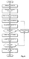
- FIG. 8 is a flowchart illustrating a process for allocating resources according to one embodiment of the present invention.
- a simultaneous hunt group can be defined to include each of the endpoints (e.g., telephones) that ring at the same time.
- the simultaneous hunt group enables a group of agents to receive or answer the incoming call on a first available basis.
- a simultaneous hunt group can be defined to include the telephones of 8 technical support agents. An incoming call to the technical support telephone number rings each of the 8 agent telephones concurrently. The first agent to pickup the telephone receives the incoming call.
- a simultaneous hunt group therefore offers an efficient way to distribute incoming calls for call center applications.
- FIG. 1A is an illustration of a system architecture according to one embodiment of the present invention.
- the illustrated embodiment includes a first site 110 and a second site 170 .
- a site represents a grouping of resources.
- a site's connectivity to a wide area network is resource constrained (e.g., bandwidth limited).
- a local area or other network provides sufficient resources such that admission control or preallocation of resources for communications channels is typically not required. More specifically, preallocation of resources is needed at site boundaries because of the contention for wide area networking resources on communication links that interconnect networks or sites.
- sites can be physically distinct from each other or merely topology-related groupings that are not in physically distinct locations.
- the first site 110 includes an edge router 115 , a first switch 120 , and a second switch 130 .
- the edge router 115 couples the first site 110 to a network 105 via a first link 191 .
- Coupled to the first switch 110 are a number of endpoints ( 121 , 122 , 123 , 124 ).
- Also coupled to the second switch 130 are a number of endpoints ( 131 , 132 , 133 , 134 ). In one embodiment of the present invention, each endpoint represents a telephone device.
- the first switch 120 is also coupled to a public switched telephone network (PSTN) 107 via a third link 193 .
- the third link 193 is an analog or digital trunk line (e.g., a T1 or E1).
- the first switch 120 provides an interface for calls originating from or terminating on the public switched telephone network 107 .
- the second site 170 includes a third switch 180 . Coupled to the third switch 180 are a number of endpoints ( 181 , 182 , 183 , 184 ). The second site 170 is coupled to the network 105 via a second link 192 .
- the third switch 180 can be directly coupled to the network 105 without the use of a router because the second site 170 includes a single switch.
- the switches 120 , 130 , 180 enable the endpoints ( 121 – 124 , 131 – 134 , 181 – 184 ) to provide telephony services. Further details on how the endpoints can be coupled to the switches 120 , 130 , 180 are described below and with reference to FIGS. 2 and 4 .
- the network 105 is a partially public or a wholly public network such as the Internet.
- the network 105 can also be a private network or include one or more distinct or logical private networks (e.g., virtual private networks).
- the illustrated communication links 191 , 192 to the network 105 can be wireline or wireless (i.e., terrestrial- or satellite-based transceivers).
- the network 105 is an IP-based wide or metropolitan area network. Communications channels on links 191 , 192 typically need to be preallocated because the links 191 , 192 can be resource limited connections to the wide or metropolitan area network.
- the public switched telephone network 107 can be coupled to multiple switches at several points within the topology.
- FIG. 1B is an illustration of a system architecture according to another embodiment of the present invention.
- the illustrated embodiment includes a first local area network (LAN) switch 125 .
- the first LAN switch 125 can be a conventional physical or link layer (e.g., Ethernet) switch or hub. Similar to the embodiment illustrated in FIG. 1A , the first switch 120 is coupled to the PSTN 107 via the third link 193 . The first switch 120 is also coupled to the first LAN switch 125 .
- LAN local area network
- Coupled to the first LAN switch 125 are a number of endpoints 126 , 127 , 128 .
- the endpoints 126 , 127 , 128 represent IP telephones that communicate data packets with the first LAN switch 125 .
- the endpoints 126 , 127 , 128 communicate with the first switch 120 to establish communications channels that are used to make and to receive telephone calls. More specifically, the first switch 120 manages call setup or resource allocation (as required) by provisioning a virtual extension for each of the endpoints 126 , 127 , 128 .
- a plurality of endpoints can be coupled to the first LAN switch 125 either directly or indirectly by using additional switches, hubs, etc.
- FIG. 1B also includes a server 140 coupled to the first LAN switch 125 .
- the server includes a processor 142 and a memory 144 .
- the processor 142 can be a conventional processing device, such as a general-purpose microprocessor.
- the memory 144 includes program instruction and is described in further detail below and with reference to FIG. 3 .
- the server 140 is configured to implement features or functions of the present invention described below and with reference to FIGS. 6–8 .
- the server 140 can implement a workgroup service that performs distributed call center applications such as a simultaneous hunt group according to the present invention. More specifically, the workgroup service can monitor a virtual extension that maps to a set of endpoints that are included in the simultaneous hunt group.
- the server 140 can also implement a softswitch service that facilitates workgroup functionality within the distributed architecture.
- the embodiment illustrated in FIG. 1B further includes a second LAN switch 150 coupled to the network 105 via a fourth link 194 . Coupled to the second LAN switch 150 are two endpoints 152 , 154 and a server 156 .
- the endpoints 152 , 154 are, for example, IP telephones.
- the server 156 can be architecturally similar to the server 140 described above. Functionally, the server 156 illustrates the distributed characteristics of the system architecture. For example, features or functions implemented by the server 140 can be shared with the server 156 .
- FIG. 1B illustrates the third switch 180 coupled to the network 105 via the second link 192 .
- the third switch 180 is also coupled to a PSTN 108 . This provides additional flexibility for placing and receiving calls via the PSTN.
- the exemplary system of FIG. 1A performs as a distributed voice over Internet protocol (VoIP) architecture.
- the first switch 120 includes an interface to the public switched telephone network 107 , which typically provides wide area connectivity.
- the first switch 120 constructs VoIP packets by placing voice data from the public switched telephone network 107 into VoIP packets for distribution within the first site 110 or the second site 170 using the network 105 .
- the first switch 120 also deconstructs VoIP packets and provides the corresponding voice data to the public switched telephone network 107 . That is, the first switch 120 bridges the network 105 and the public switched telephone network 107 .
- the first switch 120 receives an incoming call from a first caller 102 via the public switched telephone network 107 .
- the destination of the incoming call is endpoint 183 coupled to the third switch 180 and located in the second site 130 .
- the first switch 120 located in the first site 110 functions as a VoIP gateway and establishes a connection between the first caller 102 and the destination endpoint 183 .
- the first switch 120 performs a conventional admission control process to determine if the first site 110 and the second site 170 have sufficient available resources to establish the VoIP connection. If the sites 110 , 117 have sufficient resources, then a bi-directional communications channel (or media path) is set up between the first switch 120 and the third switch 180 .
- the first caller 102 and the agent at the destination endpoint 183 can then communicate over the established channel.
- the third switch 180 provides an additional path for bridging the network 105 with the public switched telephone network 108 .
- the server 140 includes call control features for routing calls to and from the PSTN 107 or 108 .
- call control functionality can also be included in the switch 120 / 130 / 180 as described in further detail below.
- the configuration illustrated in FIG. 1A or 1 B can operate with IP telephony device originated or teminated calls.
- a second caller 103 can place a call on the network 105 using, for example, VoIP-enabled telephony device.
- the media path includes one or more of the first, second, and third links 191 , 192 , 193 . If the destination is coupled to the public switched telephone network 107 , then the media path includes the first link 191 and the third link 193 .
- the first switch 120 functions as a VoIP gateway to the public switched telephone network 107 . If the destination is an endpoint within the first site 110 or the second site 170 , then a communications channel is established with the corresponding switch.
- a plurality of VoIP devices can be coupled through various network infrastructure devices (e.g., switches and routers) to the network 105 .
- establishing a communications channel includes allocating resources (e.g., bandwidth and port designations) along a media path to connect a caller and a callee.
- resources e.g., bandwidth and port designations
- two communications channels can be established so that the caller and the callee can communicate bi-directionally.
- a communications channel may be referred to singularly although one skilled in the art will recognize that two communications channels are desirable for bi-directional communications.
- the media path includes the communications links that are needed to connect the caller with the callee. Whether sites have available resources to establish a communications channel along the media path can depend upon the bandwidth of the communications links that connect those sites. Resource reservation (or admission control) is performed for each site on the media path to ensure that adequate throughput is maintained for the duration of the call.
- FIG. 2 is an illustration of one embodiment of a switch of FIG. 1A .
- the switch 120 / 130 / 180 includes a processor 210 , a network interface 215 , and a memory 144 / 220 .
- the processor 210 is shown coupled to the network interface 215 , the memory 144 / 220 , and a data bus.
- the data bus 225 includes a PSTN interface 230 , a first port interface 235 , a second port interface 240 , a third port interface 245 , and a fourth port interface 250 .
- the processor 210 can be a general-purpose microprocessor, a special-purpose microprocessing device (e.g., a microcontroller), or an application-specific integrated circuit (ASIC).
- the memory 144 / 220 includes program instructions or modules stored therein.
- the program instructions can be distributed on a computer readable medium or storage volume.
- the computer readable storage volume can be available via a public network, a private network, or the Internet.
- Program instructions can be in any appropriate form, such as source code, object code, or scripting code.
- the memory 144 / 220 can be a conventional storage device, such as electronic, optical, or magnetic memory.
- the program instructions configure the processor 210 to perform packet switching and other functions as described below.
- the network interface 215 comprises an Ethernet interface, for example, that can be coupled to the network 105 .
- the network interface 215 generally corresponds with the type of the network 105 .
- the network 105 is an Ethernet network that includes transmission control protocol (TCP) and Internet protocol (IP) data.
- TCP transmission control protocol
- IP Internet protocol
- the processor 210 transmits and receives VoIP packets from the network interface 215 .
- the PSTN interface 230 is configured to couple to the public switched telephone network 107 .
- the PSTN interface 230 comprises a framer/deframer for a T1/E1 circuit.
- the processor 210 extracts the voice data from VoIP packets and places the voice data on the data bus 225 .
- the PSTN interface 230 frames the data and places it on the designated channel of the T1/E1 circuit.
- the PSTN interface 230 deframes the data and places it on the data bus 225 .
- the processor 210 then packetizes the data from the data bus 225 and sends the packets to the network interface 215 .
- the processor 210 uses a standards-compliant VoIP packet structure.
- the PSTN interface 230 comprises an analog trunk interface. As with the network interface 215 , the PSTN interface 230 generally corresponds to and is compatible with the public switched telephone network 107 .
- the port interfaces 235 , 240 , 245 , 250 each comprise a subscriber line interface circuit that can be coupled to a telephony device or endpoint.
- the telephony device can be a conventional analog telephone.
- the port interfaces 235 , 240 , 245 , 250 can include circuits for interfacing with the data on the data bus 225 .
- the port interfaces 235 , 240 , 245 , 250 include digital signal processors, digital to analog converters, or analog to digital converters for processing the analog signals associated with conventional telephony devices and interfacing those signals with the data bus 225 .
- One skilled in the art will appreciate that although four port interfaces 235 , 240 , 245 , 250 are shown, a plurality of port interfaces can be included for coupling a plurality of endpoints to the switch 120 / 130 / 180 .
- FIG. 3 is an illustration of one embodiment of modules within the memory of FIG. 2 .
- the illustration includes several modules within the memory 144 / 220 that can be used to implement the features or functionalities of the present invention.
- the modules include a call status module 320 , a call transfer module 330 , a resource management module 340 , and a reporting module 350 . Exemplary functionality for each of these modules is now described.
- the call status module 320 performs functions such as noticing endpoint pickup and offering the call to a simultaneous hunt group.
- the call transfer module 330 coordinates resource allocation and transfers the call to the endpoint that picked up or accepted the call.
- the resource management module 340 maintains information about a site's available bandwidth or usage load.
- the reporting module 350 produces messages about the success or failure of the resource allocation for establishing a communications channel.
- a computing device within the distributed architecture such as the switch 120 / 130 / 180 and/or the server 140 / 156 , can implement the functions of each of the modules. The functions of each of the modules are also described in further detail below and with reference to FIGS. 6–8 .
- FIG. 4 is an illustration of another embodiment of a switch of FIG. 1A .
- the switch 120 / 130 / 180 includes a call processor 410 , call transfer logic 420 , and a resource monitor 430 . Similar to the embodiment of the switch 120 / 130 / 180 illustrated in FIG. 2 , FIG. 4 also includes a network interface 215 and a data bus 225 .
- the data bus 225 includes a PSTN interface 230 , a first port interface 235 , a second port interface 240 , a third port interface 245 , and a fourth port interface 250 .
- the embodiment shown in FIG. 4 includes similar functionality to the embodiment of the switch 120 / 130 / 180 shown in FIG. 2 .
- application-specific circuitry or a combination of hardware and software is used to implement, for example, the call status module 320 , a call transfer module 330 , a resource management module 340 , and a reporting module 350 .
- the call transfer logic 420 performs the function of coordinating resource allocation for establishing a communications channel and transferring the incoming call.
- the resource monitor 430 maintains information about a site's available bandwidth or usage load.
- the call processor 410 performs packet switching functions and coordinates the data flow to and from the network interface 215 and the data bus 225 .
- the call processor 410 also performs call status functions, such as noticing endpoint pickup and offering an incoming call to a simultaneous hunt group.
- FIG. 5 is a system diagram illustrating a simultaneous hunt group in accordance with the present invention.
- a simultaneous hunt group a single incoming call is concurrently offered to a plurality of endpoints.
- Each of several agents that are stationed at the endpoints has an opportunity to answer the incoming call.
- the first agent to answer the call is connected to the caller.
- FIG. 5 illustrates an example simultaneous hunt group in a distributed system architecture.
- a first site 510 , a second site 530 , and third site 550 are shown.
- the first site 510 includes a first switch 515 .
- the second site 530 includes a second switch 535 .
- the third site 550 includes a third switch 555 .
- the first switch 515 communicates with the second switch 535 using a first link 560 .
- the second switch 535 communicates with the third switch 555 using a second link 565 .
- the first link 560 and the second link 565 are illustrated as both coupled to the second switch 535 , one skilled in the art will appreciate that additional networking devices can be provided to facilitate the interconnection of the sites 510 , 530 , 550 .
- the simultaneous hunt group includes four endpoints 520 , 540 , 542 , 557 . That is, an incoming call from a caller 505 causes each of the four endpoints 520 , 540 , 542 , 557 to ring simultaneously. More specifically, the first switch 515 receives the incoming call from the caller 505 . In one embodiment of the present invention, the workgroup service executing on the server 140 notices the incoming call and offers the call to each of the four endpoints 520 , 540 , 542 , 557 . As described above, the server 140 includes program instructions for implementing a softswitch. One skilled in the art will recognize, therefore, that the server 140 can perform the steps or acts of a switch.
- the first site 510 includes one endpoint 520
- the second site 530 includes two endpoints 540 , 542
- the third site 550 includes one endpoint 557 .
- FIG. 5 also includes other endpoints that are not included in the defined hunt group. These endpoints are coupled to the switches 515 , 535 , 555 and are identified with an “X”.
- any one of the endpoints 520 , 540 , 542 , 557 in the simultaneous hunt group can answer the call from the caller 505 .
- the caller 505 is connected with the agent responsible for the endpoint 557 .
- a communications channel is established along a media path that includes the first link 560 and the second link 565 . Therefore, the each of the three sites 510 , 530 , 550 need sufficient available resources in order to establish the communications channel and transfer the caller 505 . Resource allocation is now described in further detail.
- FIG. 6 is flowchart illustrating a method for performing resource allocation for a simultaneous hunt group according to one embodiment of the present invention.
- the illustrated method begins with the call status module 320 noticing 605 the incoming call.
- the switch or server that notices 650 the incoming call determines 610 the endpoint or group of endpoints that comprise the simultaneous hunt group.
- the switch or server includes a table that associates the destination telephone number or extension number with a group of extension numbers that represent the membership of the simultaneous hunt group.
- the incoming call is then offered 615 to each endpoint in the simultaneous hunt group.
- the switches communicate control packets to inform each other to ring a particular endpoint that is part of the simultaneous hunt group.
- resource allocation or admission control is not performed during the offering 615 .
- the call status modules 320 of the switch or switches that have endpoints ringing monitor the status.
- the call status module 320 notices 620 if the endpoint accepts the call.
- One example of call acceptance is an agent taking a conventional telephone device off-hook (i.e., picking up the handset).
- pressing a button or clicking an icon with a mouse can also indicate call acceptance.
- the switch or server After an endpoint has accepted the incoming call, the switch or server performs resource allocation and call transfer. Because it is known that only one endpoint within the simultaneous hunt group will answer the incoming call (i.e., the callee), embodiments of the present invention allocate resources to establish a single communications channel along the media path that connects the caller and the callee.
- One advantage of not preallocating resources for each of the endpoints in the simultaneous hunt group is that there are no extra resources that need to be released for the endpoints that did not answer the incoming call. Also, preallocation inflates network usage and can result in other calls being denied resources that would otherwise be available.
- resources are allocated 625 for the caller site.
- the caller site is the site in which the call originates.
- the call transfer module 330 makes a resources allocation request to the resource management module 340 . If resources are not available and the request is not successful 630 , then a failure is reported 635 .
- the reporting module 350 can play a pre-recorded message such as “the call cannot be completed at this time.”
- the failure is reported 635 to the callee, and the process returns to step 620 .
- the call status module 320 continues to notice 620 if an endpoint accepts the call. More specifically, the caller continues to hear ringing and the endpoints continue ringing until the transfer to the callee has been completed successfully. Because the system's resource usage is temporally dynamic, resources may be available by the time another agent answers the call.
- the transfer is initiated 640 to the callee site. Resources are then allocated 645 for the callee site.
- the call transfer module 330 makes a resources allocation request to the resource management module 340 . If resources are not available and the request is not successful 650 , then a failure is reported 635 and, as described above, the process returns to step 620 .
- the reporting module 350 can play a pre-recorded message such as “the call cannot be completed at this time.”
- the call transfer module 330 then completes 655 the transfer and informs the switch or switches that have endpoints ringing as part of the simultaneous hunt group that the transfer has been completed.
- a system architecture including a single switch can perform the resource allocation method illustrated, for example, in FIG. 6 .
- the IP telephones can be coupled to local or wide area networking devices in various sites or configurations. Admission control or resource reservation can be needed to communicate with IP telephones using resource-limited (e.g., bandwidth constrained) communications links.
- resource-limited e.g., bandwidth constrained
- the step of allocating 625 resources for the caller site can be omitted. More specifically, where it is known that a communication link that couples a site to a wider area connection provides resources that equal or exceed that maximum potential resource usage of that site, admission control or preallocation of resources for communications channel is typically not required.
- FIG. 7 is a flowchart illustrating a method for performing resource allocation for a simultaneous hunt group according to another embodiment of the present invention. Similar to the embodiment shown in FIG. 6 , the process illustrated in FIG. 7 begins with noticing 705 an incoming call and determining 710 the endpoints for the call. After the endpoints are determined, resources are allocated 715 for the call. In this embodiment, communications channels are established between the affected switches and sites, then the call is offered 720 to the endpoints. Although it is known that only one agent or endpoint will eventually answer the call, some resources are preallocated along the potential media paths.
- two communications channels are established over the first link 560 .
- One of these two channels is for the endpoint 557 in the third site 550 , if that endpoint is the one to answer the call.
- the other of the two channels is for one of the two endpoints 540 , 542 in the second site 530 , if one of those endpoints is the one to answer the call.
- extra resources are allocated along the potential media paths, one advantage of this allocation method is that a communications channel is not allocated for each of the endpoints that may answer the call.
- the call status module 320 of the affected switches notices 725 an endpoint accept or answer the call.
- the caller is then transferred 730 along one of the established communications channels to the callee. Now that a particular one of the endpoints has answered the call, the potential media paths to other endpoints within the simultaneous hunt group are no longer needed. Therefore, the extra resources that were allocated between the switches are released 735 .
- the call transfer module 330 can inform the resource management module 340 to release the previously allocated resources.
- FIG. 8 is a flowchart illustrating a process for allocating resources according to one embodiment of the present invention.
- FIG. 8 illustrates in further detail an exemplary process for allocating resources 625 / 645 / 715 .
- the resource management module 340 or the resource monitor 430 determines 805 the resources required for the call.
- a typical communications channel can require 26 Kbps. That is, a typical duplex telephone conversion can require 52 Kbps for bi-directional communications channels.
- Call setup, control commands, resource allocation, or admission control data for example, consume relatively few resources when compared with voice communications channels. Therefore the resource management module 340 or the resource monitor 430 generally monitor and manage the communications channel resources.
- resource allocation is measured in units of a usage load.
- the resource management module 340 is configured to allow a predetermined number of concurrent calls with a particular voice quality.
- the predetermined number can depend upon the data rate of the site's network connection. For example, with reference to FIG. 1A , if the first link 191 is capable of 1.55 Mbps, then the resource management module 340 for the first switch 120 and the second switch 130 can determine a usage load for the first site 110 .
- the resource management module 340 can be configured to compare the bandwidth currently in use with the total bandwidth available on the wide area network connection or a bandwidth constrained site connection.
- the resource management module 340 updates status or reserves resources 810 .
- the resource management module 340 grants resource allocation requests when the request will not cause the maximum throughput of the network connection to be exceeded. If the request is granted, the usage load or other status metric is updated 810 .
- the resource management module 340 can implement a serialized, transaction-based request system.
Abstract
Description
Claims (20)
Priority Applications (1)
| Application Number | Priority Date | Filing Date | Title |
|---|---|---|---|
| US10/370,915 US7003091B1 (en) | 2003-02-21 | 2003-02-21 | Resource allocation for simultaneous hunt group |
Applications Claiming Priority (1)
| Application Number | Priority Date | Filing Date | Title |
|---|---|---|---|
| US10/370,915 US7003091B1 (en) | 2003-02-21 | 2003-02-21 | Resource allocation for simultaneous hunt group |
Publications (1)
| Publication Number | Publication Date |
|---|---|
| US7003091B1 true US7003091B1 (en) | 2006-02-21 |
Family
ID=35810721
Family Applications (1)
| Application Number | Title | Priority Date | Filing Date |
|---|---|---|---|
| US10/370,915 Active 2024-07-25 US7003091B1 (en) | 2003-02-21 | 2003-02-21 | Resource allocation for simultaneous hunt group |
Country Status (1)
| Country | Link |
|---|---|
| US (1) | US7003091B1 (en) |
Cited By (23)
| Publication number | Priority date | Publication date | Assignee | Title |
|---|---|---|---|---|
| US20040032859A1 (en) * | 2002-08-15 | 2004-02-19 | Miao Kai X. | Managing a remote resource |
| US20070037562A1 (en) * | 2005-08-11 | 2007-02-15 | Smith-Kerker Penny L | Method and system for call management within a cellular telephone group subscription |
| US7286661B1 (en) * | 2007-05-01 | 2007-10-23 | Unison Technologies Llc | Systems and methods for scalable hunt-group management |
| US20080273678A1 (en) * | 2007-05-01 | 2008-11-06 | Igor Balk | Systems and methods for phone call management |
| US20080304473A1 (en) * | 2007-06-11 | 2008-12-11 | At&T Corp. | Enhanced terminal adapter |
| US20090041216A1 (en) * | 2007-05-16 | 2009-02-12 | Unison Technologies Llc | Systems and methods for providing unified collaboration systems with conditional communication handling |
| US20090041052A1 (en) * | 2007-05-16 | 2009-02-12 | Unison Technologies Llc | Systems and methods for providing unified collaboration systems with user selectable reply format |
| US20090110172A1 (en) * | 2007-10-26 | 2009-04-30 | Musa Raoul Unmehopa | Method of queuing and returning calls to an interactive voice response system |
| US7593515B2 (en) | 2007-05-16 | 2009-09-22 | Unison Technologies, Inc. | Systems and methods for providing unified collaboration systems with combined communication log |
| US20090245232A1 (en) * | 2008-03-25 | 2009-10-01 | Shoretel, Inc. | Group paging synchronization for voip system |
| US7620164B1 (en) * | 2005-12-21 | 2009-11-17 | At&T Corp. | Method and apparatus for providing extension management in voice over internet protocol premises |
| US20100020947A1 (en) * | 2008-07-28 | 2010-01-28 | Shoretel, Inc. | Systems and methods for providing voicemail features in a voip system |
| US20100080213A1 (en) * | 2008-09-30 | 2010-04-01 | Shoretel, Inc. | Systems and methods for utilizing a spare switch in a distributed voip system |
| US20100246568A1 (en) * | 2009-03-31 | 2010-09-30 | Tovino Michael S W | Telephony system with intelligent endpoints or intelligent switches to reduce dependency of endpoints on application server |
| US20110249557A1 (en) * | 2008-12-19 | 2011-10-13 | Indian Institute Of Science | Centralized Wireless Manager (WiM) for Performance Management of IEEE 802.11 and a Method Thereof |
| US20110317686A1 (en) * | 2010-06-24 | 2011-12-29 | Michael South | Systems and methods of establishing user groups in an internet protocol environment |
| US8359354B1 (en) * | 2009-03-30 | 2013-01-22 | Shoretel, Inc. | Methods for providing a status to devices in a distributed system |
| US8468121B1 (en) | 2011-09-29 | 2013-06-18 | Shoretel, Inc. | Resolving resource time intervals in a distributed system |
| US8493892B1 (en) | 2009-03-30 | 2013-07-23 | Shoretel, Inc. | Resolving conflicts in distributed systems |
| EP2713590A1 (en) * | 2012-09-28 | 2014-04-02 | Avaya Inc. | Increasing contact center efficiency via multi-cast and multi-item presentation |
| US20140093063A1 (en) * | 2011-06-03 | 2014-04-03 | Huawei Technologies Co., Ltd. | Method, call center, and system for agent terminal to answer call |
| US9325599B2 (en) | 2009-03-30 | 2016-04-26 | Shoretel, Inc. | Methods for providing a status to devices in a distributed system |
| US20170149969A1 (en) * | 2015-11-24 | 2017-05-25 | Avaya Inc. | Electronic communication routing based data accuracy |
Citations (7)
| Publication number | Priority date | Publication date | Assignee | Title |
|---|---|---|---|---|
| US5515428A (en) * | 1993-04-16 | 1996-05-07 | Mitel Corporation | Multiple queue resource management |
| US5557667A (en) * | 1994-03-18 | 1996-09-17 | At&T | Method and system for multi-channel data automatic call distribution for sequentially launched calls |
| US6404885B1 (en) * | 1998-12-31 | 2002-06-11 | At&T Corp. | Method and system for providing multiple classes of telephone access service |
| US6466661B2 (en) * | 1996-06-12 | 2002-10-15 | Alcatel | Method of establishing a connection, as well as exchange, service computer and communications network |
| US6473501B1 (en) * | 1999-06-11 | 2002-10-29 | Telefonaktiebolaget L M Ericsson (Publ) | Concurrent hunt group searching methods and arrangements |
| US6751310B1 (en) * | 2000-04-05 | 2004-06-15 | Concerto Software, Inc. | System and method for prioritizing telephone call campaigns based on campaign productivity |
| US6766012B1 (en) * | 1999-10-20 | 2004-07-20 | Concerto Software, Inc. | System and method for allocating agent resources to a telephone call campaign based on agent productivity |
-
2003
- 2003-02-21 US US10/370,915 patent/US7003091B1/en active Active
Patent Citations (7)
| Publication number | Priority date | Publication date | Assignee | Title |
|---|---|---|---|---|
| US5515428A (en) * | 1993-04-16 | 1996-05-07 | Mitel Corporation | Multiple queue resource management |
| US5557667A (en) * | 1994-03-18 | 1996-09-17 | At&T | Method and system for multi-channel data automatic call distribution for sequentially launched calls |
| US6466661B2 (en) * | 1996-06-12 | 2002-10-15 | Alcatel | Method of establishing a connection, as well as exchange, service computer and communications network |
| US6404885B1 (en) * | 1998-12-31 | 2002-06-11 | At&T Corp. | Method and system for providing multiple classes of telephone access service |
| US6473501B1 (en) * | 1999-06-11 | 2002-10-29 | Telefonaktiebolaget L M Ericsson (Publ) | Concurrent hunt group searching methods and arrangements |
| US6766012B1 (en) * | 1999-10-20 | 2004-07-20 | Concerto Software, Inc. | System and method for allocating agent resources to a telephone call campaign based on agent productivity |
| US6751310B1 (en) * | 2000-04-05 | 2004-06-15 | Concerto Software, Inc. | System and method for prioritizing telephone call campaigns based on campaign productivity |
Cited By (39)
| Publication number | Priority date | Publication date | Assignee | Title |
|---|---|---|---|---|
| US20040032859A1 (en) * | 2002-08-15 | 2004-02-19 | Miao Kai X. | Managing a remote resource |
| US20070037562A1 (en) * | 2005-08-11 | 2007-02-15 | Smith-Kerker Penny L | Method and system for call management within a cellular telephone group subscription |
| US7620164B1 (en) * | 2005-12-21 | 2009-11-17 | At&T Corp. | Method and apparatus for providing extension management in voice over internet protocol premises |
| US20100061365A1 (en) * | 2005-12-21 | 2010-03-11 | Farah Jeffrey J | Method and apparatus for providing extension management in voice over internet protocol customer premises |
| US20080273686A1 (en) * | 2007-05-01 | 2008-11-06 | Unison Technologies Llc | Systems and methods for scalable hunt-group management |
| US20090067595A1 (en) * | 2007-05-01 | 2009-03-12 | Unison Technologies Llc | Systems and methods for phone call management |
| US20080273678A1 (en) * | 2007-05-01 | 2008-11-06 | Igor Balk | Systems and methods for phone call management |
| US7596217B2 (en) | 2007-05-01 | 2009-09-29 | Unison Technologies, Inc. | Systems and methods for phone call management |
| US7286661B1 (en) * | 2007-05-01 | 2007-10-23 | Unison Technologies Llc | Systems and methods for scalable hunt-group management |
| US7738650B2 (en) | 2007-05-01 | 2010-06-15 | Unison Technologies, Inc. | Systems and methods for scalable hunt-group management |
| US20090041216A1 (en) * | 2007-05-16 | 2009-02-12 | Unison Technologies Llc | Systems and methods for providing unified collaboration systems with conditional communication handling |
| US20090041052A1 (en) * | 2007-05-16 | 2009-02-12 | Unison Technologies Llc | Systems and methods for providing unified collaboration systems with user selectable reply format |
| US7593515B2 (en) | 2007-05-16 | 2009-09-22 | Unison Technologies, Inc. | Systems and methods for providing unified collaboration systems with combined communication log |
| US7783023B2 (en) | 2007-05-16 | 2010-08-24 | Unison Technologies, Inc. | Systems and methods for providing unified collaboration systems with conditional communication handling |
| US20080304473A1 (en) * | 2007-06-11 | 2008-12-11 | At&T Corp. | Enhanced terminal adapter |
| US20090110172A1 (en) * | 2007-10-26 | 2009-04-30 | Musa Raoul Unmehopa | Method of queuing and returning calls to an interactive voice response system |
| US8335209B2 (en) | 2008-03-25 | 2012-12-18 | Shoretel, Inc. | Group paging synchronization for VoIP system |
| US20090245232A1 (en) * | 2008-03-25 | 2009-10-01 | Shoretel, Inc. | Group paging synchronization for voip system |
| US20100020947A1 (en) * | 2008-07-28 | 2010-01-28 | Shoretel, Inc. | Systems and methods for providing voicemail features in a voip system |
| WO2010014495A1 (en) * | 2008-07-28 | 2010-02-04 | Shoretel, Inc. | Systems and methods for providing voicemail features in a voip system |
| US8059795B2 (en) | 2008-07-28 | 2011-11-15 | Shoretel, Inc. | Systems and methods for providing voicemail features in a VoIP system |
| US20100080213A1 (en) * | 2008-09-30 | 2010-04-01 | Shoretel, Inc. | Systems and methods for utilizing a spare switch in a distributed voip system |
| US7990953B2 (en) | 2008-09-30 | 2011-08-02 | Shoretel, Inc. | Systems and methods for utilizing a spare switch in a distributed VOIP system |
| US20110249557A1 (en) * | 2008-12-19 | 2011-10-13 | Indian Institute Of Science | Centralized Wireless Manager (WiM) for Performance Management of IEEE 802.11 and a Method Thereof |
| US9325599B2 (en) | 2009-03-30 | 2016-04-26 | Shoretel, Inc. | Methods for providing a status to devices in a distributed system |
| US8493892B1 (en) | 2009-03-30 | 2013-07-23 | Shoretel, Inc. | Resolving conflicts in distributed systems |
| US8359354B1 (en) * | 2009-03-30 | 2013-01-22 | Shoretel, Inc. | Methods for providing a status to devices in a distributed system |
| WO2010114661A1 (en) * | 2009-03-31 | 2010-10-07 | Shore Tel, Inc. | Telephony system with intelligent endpoints or intelligent switches to reduce dependency of endpoints on application server |
| US9008076B2 (en) | 2009-03-31 | 2015-04-14 | Shoretel, Inc. | Telephony system with intelligent endpoints or intelligent switches to reduce dependency of endpoints on application server |
| US20100246568A1 (en) * | 2009-03-31 | 2010-09-30 | Tovino Michael S W | Telephony system with intelligent endpoints or intelligent switches to reduce dependency of endpoints on application server |
| US20120014293A1 (en) * | 2010-06-24 | 2012-01-19 | Lazzaro Nicholas P | Systems and methods of establishing user groups in an internet protocol environment |
| US20120014382A1 (en) * | 2010-06-24 | 2012-01-19 | Lazzaro Nicholas P | Systems and methods for terminating communication requests |
| US20110317686A1 (en) * | 2010-06-24 | 2011-12-29 | Michael South | Systems and methods of establishing user groups in an internet protocol environment |
| US20140093063A1 (en) * | 2011-06-03 | 2014-04-03 | Huawei Technologies Co., Ltd. | Method, call center, and system for agent terminal to answer call |
| US8468121B1 (en) | 2011-09-29 | 2013-06-18 | Shoretel, Inc. | Resolving resource time intervals in a distributed system |
| EP2713590A1 (en) * | 2012-09-28 | 2014-04-02 | Avaya Inc. | Increasing contact center efficiency via multi-cast and multi-item presentation |
| US9357066B2 (en) | 2012-09-28 | 2016-05-31 | Avaya Inc. | Increasing contact center efficiency via multi-cast and multi-item presentation |
| US20170149969A1 (en) * | 2015-11-24 | 2017-05-25 | Avaya Inc. | Electronic communication routing based data accuracy |
| US9854098B2 (en) * | 2015-11-24 | 2017-12-26 | Avaya Inc. | Electronic communication routing based data accuracy |
Similar Documents
| Publication | Publication Date | Title |
|---|---|---|
| US7003091B1 (en) | Resource allocation for simultaneous hunt group | |
| CN101151858B (en) | System and method for providing bandwidth reservations in a resource reservation setup protocol, RSVP, environment | |
| US7912038B2 (en) | System and method for utilizing circuit switched and packet switched resources | |
| CA2226447C (en) | Distributed network control and fabric application interface | |
| JP4390080B2 (en) | In-band call association signaling for single number destinations | |
| US5848145A (en) | Automatic learning of network routing using random routes | |
| EP0660572A2 (en) | Location dependent service for a wireless telephone | |
| JP2006191615A (en) | Alternative path selection for media connection in single communication system between public or private net facilities | |
| JPH1013534A (en) | Controller for communication network | |
| JP2002314617A (en) | Ip packet access gateway(ip pag) system and method for managing ip bearer path between ip endpoints, and computer program product | |
| US6603760B1 (en) | System and method for gradual transition of local phone services from PSTN to next generation network | |
| JP3895390B2 (en) | Method and apparatus for conducting a conference in an extensible telecommunications system | |
| CN112995427B (en) | Fixed telephone line network access system | |
| US5936951A (en) | Dynamic infrastructure | |
| US7620164B1 (en) | Method and apparatus for providing extension management in voice over internet protocol premises | |
| US7881282B2 (en) | System and method for interfacing a broadband network and a circuit switched network | |
| JP4238259B2 (en) | Method for managing held telephone calls in a call transfer system | |
| WO2005096609A1 (en) | Communication network system, access gateway, and control method thereof | |
| US6963574B2 (en) | Conversation of access network bandwidth during multiuser call connections in a broadband telephony network | |
| CA2251313A1 (en) | Inhomogeneous connections | |
| JP3058088B2 (en) | Circuit switching method using in-band channel | |
| JP2000196675A (en) | Method and device for controlling connection of communication network and communication system using them | |
| Yu | A Global Packet-Phone Network for Global Enterprises-Theory and Practice | |
| CA2219168A1 (en) | Dynamic infrastructure | |
| KR20030030378A (en) | Method For Managing V5.2 Subscriber Status On Access Network |
Legal Events
| Date | Code | Title | Description |
|---|---|---|---|
| AS | Assignment |
Owner name: SHORELINE COMMUNICATIONS, INC., CALIFORNIA Free format text: ASSIGNMENT OF ASSIGNORS INTEREST;ASSIGNORS:BURNS, ROBERT R.;TONOGAI, DALE;VAN GUNDY, SCOTT A.;REEL/FRAME:014111/0316;SIGNING DATES FROM 20030425 TO 20030428 |
|
| AS | Assignment |
Owner name: SHORETEL, INC., CALIFORNIA Free format text: CHANGE OF NAME;ASSIGNOR:SHORELINE COMMUNICATIONS, INC.;REEL/FRAME:016448/0683 Effective date: 20040414 |
|
| STCF | Information on status: patent grant |
Free format text: PATENTED CASE |
|
| FEPP | Fee payment procedure |
Free format text: PAT HOLDER NO LONGER CLAIMS SMALL ENTITY STATUS, ENTITY STATUS SET TO UNDISCOUNTED (ORIGINAL EVENT CODE: STOL); ENTITY STATUS OF PATENT OWNER: LARGE ENTITY |
|
| REFU | Refund |
Free format text: REFUND - SURCHARGE, PETITION TO ACCEPT PYMT AFTER EXP, UNINTENTIONAL (ORIGINAL EVENT CODE: R2551); ENTITY STATUS OF PATENT OWNER: LARGE ENTITY |
|
| FPAY | Fee payment |
Year of fee payment: 4 |
|
| FPAY | Fee payment |
Year of fee payment: 8 |
|
| AS | Assignment |
Owner name: SILICON VALLEY BANK, CALIFORNIA Free format text: SECURITY INTEREST;ASSIGNOR:SHORETEL, INC.;REEL/FRAME:034038/0741 Effective date: 20141022 |
|
| FPAY | Fee payment |
Year of fee payment: 12 |
|
| AS | Assignment |
Owner name: CITIZENS BANK, N.A., AS ADMINISTRATIVE AGENT, MASSACHUSETTS Free format text: SECURITY INTEREST;ASSIGNOR:SHORETEL, INC.;REEL/FRAME:043829/0711 Effective date: 20170925 Owner name: CITIZENS BANK, N.A., AS ADMINISTRATIVE AGENT, MASS Free format text: SECURITY INTEREST;ASSIGNOR:SHORETEL, INC.;REEL/FRAME:043829/0711 Effective date: 20170925 Owner name: SHORETEL, INC., CALIFORNIA Free format text: RELEASE BY SECURED PARTY;ASSIGNOR:SILICON VALLEY BANK;REEL/FRAME:043993/0430 Effective date: 20170925 |
|
| AS | Assignment |
Owner name: SHORETEL, INC., CALIFORNIA Free format text: MERGER AND CHANGE OF NAME;ASSIGNORS:MITEL NETWORKS, INC.;SHORETEL, INC.;REEL/FRAME:047239/0183 Effective date: 20171229 Owner name: MITEL NETWORKS, INC., ARIZONA Free format text: CHANGE OF NAME;ASSIGNOR:SHORETEL, INC.;REEL/FRAME:047239/0088 Effective date: 20171229 |
|
| AS | Assignment |
Owner name: SHORETEL, INC., CALIFORNIA Free format text: RELEASE BY SECURED PARTY;ASSIGNOR:CITIZENS BANK, N.A., AS ADMINISTRATIVE AGENT;REEL/FRAME:047713/0843 Effective date: 20181130 |
|
| AS | Assignment |
Owner name: CREDIT SUISSE AG, CAYMAN ISLANDS BRANCH, AS COLLATERAL AGENT, NEW YORK Free format text: SECURITY INTEREST;ASSIGNOR:MITEL NETWORKS, INC.;REEL/FRAME:047909/0814 Effective date: 20181207 Owner name: CREDIT SUISSE AG, CAYMAN ISLANDS BRANCH, AS COLLATERAL AGENT, NEW YORK Free format text: SECURITY INTEREST;ASSIGNOR:MITEL NETWORKS, INC.;REEL/FRAME:047988/0478 Effective date: 20181207 Owner name: CREDIT SUISSE AG, CAYMAN ISLANDS BRANCH, AS COLLAT Free format text: SECURITY INTEREST;ASSIGNOR:MITEL NETWORKS, INC.;REEL/FRAME:047909/0814 Effective date: 20181207 Owner name: CREDIT SUISSE AG, CAYMAN ISLANDS BRANCH, AS COLLAT Free format text: SECURITY INTEREST;ASSIGNOR:MITEL NETWORKS, INC.;REEL/FRAME:047988/0478 Effective date: 20181207 |
|
| AS | Assignment |
Owner name: CREDIT SUISSE AG, CAYMAN ISLANDS BRANCH, AS COLLATERAL AGENT, NEW YORK Free format text: SECURITY INTEREST;ASSIGNORS:MITEL (DELAWARE), INC.;MITEL NETWORKS, INC.;MITEL COMMUNICATIONS, INC.;REEL/FRAME:061830/0760 Effective date: 20221018 Owner name: CREDIT SUISSE AG, CAYMAN ISLANDS BRANCH, AS COLLATERAL AGENT, NEW YORK Free format text: SECURITY INTEREST;ASSIGNORS:MITEL (DELAWARE), INC.;MITEL NETWORKS, INC.;MITEL COMMUNICATIONS, INC.;REEL/FRAME:061830/0715 Effective date: 20221018 Owner name: CREDIT SUISSE AG, CAYMAN ISLANDS BRANCH, AS COLLATERAL AGENT, NEW YORK Free format text: SECURITY INTEREST;ASSIGNORS:MITEL (DELAWARE), INC.;MITEL NETWORKS, INC.;MITEL COMMUNICATIONS, INC.;REEL/FRAME:061830/0643 Effective date: 20221018 |