US7009473B2 - Ground-fault circuit interrupter with reverse wiring protection - Google Patents
Ground-fault circuit interrupter with reverse wiring protection Download PDFInfo
- Publication number
- US7009473B2 US7009473B2 US11/129,699 US12969905A US7009473B2 US 7009473 B2 US7009473 B2 US 7009473B2 US 12969905 A US12969905 A US 12969905A US 7009473 B2 US7009473 B2 US 7009473B2
- Authority
- US
- United States
- Prior art keywords
- hot
- disposed
- conductors
- disconnecting
- coil
- Prior art date
- Legal status (The legal status is an assumption and is not a legal conclusion. Google has not performed a legal analysis and makes no representation as to the accuracy of the status listed.)
- Expired - Fee Related, expires
Links
Images


Classifications
-
- H—ELECTRICITY
- H01—ELECTRIC ELEMENTS
- H01R—ELECTRICALLY-CONDUCTIVE CONNECTIONS; STRUCTURAL ASSOCIATIONS OF A PLURALITY OF MUTUALLY-INSULATED ELECTRICAL CONNECTING ELEMENTS; COUPLING DEVICES; CURRENT COLLECTORS
- H01R13/00—Details of coupling devices of the kinds covered by groups H01R12/70 or H01R24/00 - H01R33/00
- H01R13/66—Structural association with built-in electrical component
- H01R13/70—Structural association with built-in electrical component with built-in switch
- H01R13/713—Structural association with built-in electrical component with built-in switch the switch being a safety switch
- H01R13/7135—Structural association with built-in electrical component with built-in switch the switch being a safety switch with ground fault protector
-
- H—ELECTRICITY
- H01—ELECTRIC ELEMENTS
- H01H—ELECTRIC SWITCHES; RELAYS; SELECTORS; EMERGENCY PROTECTIVE DEVICES
- H01H83/00—Protective switches, e.g. circuit-breaking switches, or protective relays operated by abnormal electrical conditions otherwise than solely by excess current
- H01H83/02—Protective switches, e.g. circuit-breaking switches, or protective relays operated by abnormal electrical conditions otherwise than solely by excess current operated by earth fault currents
- H01H83/04—Protective switches, e.g. circuit-breaking switches, or protective relays operated by abnormal electrical conditions otherwise than solely by excess current operated by earth fault currents with testing means for indicating the ability of the switch or relay to function properly
-
- H—ELECTRICITY
- H01—ELECTRIC ELEMENTS
- H01R—ELECTRICALLY-CONDUCTIVE CONNECTIONS; STRUCTURAL ASSOCIATIONS OF A PLURALITY OF MUTUALLY-INSULATED ELECTRICAL CONNECTING ELEMENTS; COUPLING DEVICES; CURRENT COLLECTORS
- H01R13/00—Details of coupling devices of the kinds covered by groups H01R12/70 or H01R24/00 - H01R33/00
- H01R13/648—Protective earth or shield arrangements on coupling devices, e.g. anti-static shielding
- H01R13/652—Protective earth or shield arrangements on coupling devices, e.g. anti-static shielding with earth pin, blade or socket
-
- H—ELECTRICITY
- H01—ELECTRIC ELEMENTS
- H01R—ELECTRICALLY-CONDUCTIVE CONNECTIONS; STRUCTURAL ASSOCIATIONS OF A PLURALITY OF MUTUALLY-INSULATED ELECTRICAL CONNECTING ELEMENTS; COUPLING DEVICES; CURRENT COLLECTORS
- H01R24/00—Two-part coupling devices, or either of their cooperating parts, characterised by their overall structure
- H01R24/76—Two-part coupling devices, or either of their cooperating parts, characterised by their overall structure with sockets, clips or analogous contacts and secured to apparatus or structure, e.g. to a wall
- H01R24/78—Two-part coupling devices, or either of their cooperating parts, characterised by their overall structure with sockets, clips or analogous contacts and secured to apparatus or structure, e.g. to a wall with additional earth or shield contacts
-
- H—ELECTRICITY
- H01—ELECTRIC ELEMENTS
- H01H—ELECTRIC SWITCHES; RELAYS; SELECTORS; EMERGENCY PROTECTIVE DEVICES
- H01H47/00—Circuit arrangements not adapted to a particular application of the relay and designed to obtain desired operating characteristics or to provide energising current
- H01H47/002—Monitoring or fail-safe circuits
-
- H—ELECTRICITY
- H01—ELECTRIC ELEMENTS
- H01R—ELECTRICALLY-CONDUCTIVE CONNECTIONS; STRUCTURAL ASSOCIATIONS OF A PLURALITY OF MUTUALLY-INSULATED ELECTRICAL CONNECTING ELEMENTS; COUPLING DEVICES; CURRENT COLLECTORS
- H01R13/00—Details of coupling devices of the kinds covered by groups H01R12/70 or H01R24/00 - H01R33/00
- H01R13/64—Means for preventing incorrect coupling
- H01R13/641—Means for preventing incorrect coupling by indicating incorrect coupling; by indicating correct or full engagement
-
- H—ELECTRICITY
- H01—ELECTRIC ELEMENTS
- H01R—ELECTRICALLY-CONDUCTIVE CONNECTIONS; STRUCTURAL ASSOCIATIONS OF A PLURALITY OF MUTUALLY-INSULATED ELECTRICAL CONNECTING ELEMENTS; COUPLING DEVICES; CURRENT COLLECTORS
- H01R2103/00—Two poles
Definitions
- the present invention generally relates to the field of leakage current protection devices, and more particularly relates to ground-fault circuit interrupters with reverse wiring protection features.
- GFCI ground-fault circuit interrupter
- Power outlet receptacles equipped with GFCIs are generally known, and are described in, e.g., U.S. Pat. Nos. 4,237,435, 4,247,840 and 4,595,894. These devices have a shortcoming in that they cannot prevent power leakage when their electrical connecting wires are reversed upon installation, which presents a real safety hazard.
- the reset button (RESET) and test button (TEST) can still be depressed as if in normal operation to break or make the connection between the input and output of the GFCI receptacle.
- the receptacle under such a condition will not function to provide ground fault protection, and moreover, will mislead the user into assuming that the receptacle is functioning properly, possibly causing personal harm to the user.
- embodiments of the present invention provide a safer GFCI receptacle with reverse wiring protection that can be installed in the interior of buildings.
- the receptacle can effectively function to cut off electrical output.
- the present invention is a circuit interrupting device having: hot and neutral input conductors for connecting to hot and neutral lines of a power source; hot and neutral output conductors for connecting to hot and neutral lines of a load; a coil electrically connected to the hot and neutral input conductors; a moveable piece capable of moving from a first position to a second position when the coil is energized; a switch electrically connected to the coil, the switch having a locking mechanism cooperating with the moveable piece to lock the moveable piece when it is in its second position, the switch being in a closed condition that electrically connects the coil to the input conductors when the moveable piece is in its first position, and an open condition that electrically disconnects the coil from the input conductors when the moveable piece is in its second position; and a disconnecting mechanism having a guiding member coupled to a RESET button, and a moveable part coupled to the guiding member, the disconnecting mechanism capable of moving between a disconnecting state that electrically disconnects the input conductors from the output
- the present invention has many unique features and advantages.
- the device not only has leakage current protection function, but also has a reliable reverse wiring protection function. If the wires from the power source are mistakenly connected to the LOAD side of the GFCI receptacle, the coil will fail to move the moveable piece, preventing the device from being reset by the RESET button. As a result, the GFCI receptacle will have no power output, thereby avoiding possible harm to its users.
- FIG. 1 is a plan view of the front of a device according to an embodiment of the present invention.
- FIGS. 2A and 2B are an exploded view of the device of FIG. 1 .
- FIG. 3 shows a part of the internal structures of the device of FIG. 1 .
- FIGS. 4A and 4B are an exploded view of a part of the device of FIG. 1 .
- FIG. 5 is a circuit diagram of the device according to an embodiment of the present invention.
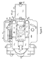
- FIG. 6 is a cross-sectional view along the line A—A of FIG. 1 illustrating a connection condition when the device is correctly installed.
- FIG. 7 is a cross-sectional view along the line A—A of FIG. 1 illustrating a disconnection condition when the device is correctly installed.
- FIG. 8 is a cross-sectional view along the line A—A of FIG. 1 illustrating a disconnection condition when the device is incorrectly installed.
- a GFCI receptacle with reverse wiring protection includes a housing that has a cover 1 and a base 5 , a mounting plate 2 , an insulating member 3 , and an electrical component mounting member 4 .
- the mounting plate 2 is disposed between the cover 1 and the insulating member 3 and is connected to the ground by a conductor.
- the insulating member 3 is disposed between the mounting plate 2 and the electrical component mounting member 4 , and is provided with hot (power) and neutral (white) output conductors.
- the electrical component mounting member 4 is disposed between the insulating member 3 and the base 5 and within the base 5 , and is provided with input conductors for connecting to the hot and neutral lines of the power source.
- the electrical component mounting member 4 is additionally provided with a disconnecting mechanism for disconnecting the output conductors and input conductors, as well as a differential transformer for detecting a leakage current and a mechanism for preventing erroneous reverse connection of the input and output lines.
- the cover 1 is provided with two outlets 6 , 7 each for receiving a plug, an opening for a TEST button 8 , and an opening for a RESET button 9 .
- the mounting plate 2 is provided with grounding connections 10 , 11 and ground mounting screw 12 .
- Grounding connectors 10 , 11 are for connecting to corresponding ground prongs of plugs inserted into the outlets 6 , 7 .
- the ground mounting screw 12 is screwed into the grounding conductor hole 13 of the base 5 , and is electrically connected to the ground through conductors.
- hot and neutral output conductors 14 , 15 are disposed adjacent the insulating member 3 .
- the output conductors 14 , 15 are provided with insertion plates 16 , 17 and 18 , 19 for connecting to corresponding hot and neutral prongs of plugs inserted into the outlets 6 , 7 .
- Output conductors 14 , 15 are additionally provided with U-shaped hot and neutral output connectors 20 , 21 , which are disposed on the sides of the base 5 and are coupled to output connecting screws 22 , 23 .
- Output conductors 14 , 15 also have a pair of electrical terminals 24 , 25 corresponding to hot and neutral moveable terminals 26 , 27 provided on the electrical component mounting member 4 .
- a test plate 28 is provided on the hot output conductor 14 and disposed beneath the TEST button 8 . Beneath the test plate 28 is a metal conductor 100 electrically connected to the ground or the neutral line of the power source (see FIG. 6 ).
- the electrical component mounting member 4 disposed in the base 5 has a pair of hot and neutral input conductors 29 , 30 connected to hot and neutral lines of the power source, respectively.
- Conductors 29 , 30 are provided with U-shaped slots for receiving connecting screws 31 , 32 , respectively, which are connected to the hot and neutral lines of the power source.
- Disposed between the input conductor 29 , 30 and through a space formed thereby is a differential transformer 33 (see FIG. 5 ).
- a pair of input connector arms 34 , 35 connected to the hot and neutral lines of the power source.
- each of connector arms 34 , 35 passes through the transformer 33 and is connected through electrical component mounting member 4 to the hot and neutral input conductors 29 , 30 , respectively.
- On the other end of each of connector arms 34 , 35 is disposed hot and neutral moveable terminals 26 , 27 , respectively, which are connectable to electrical terminals 24 , 25 of the hot and neutral output conductors 14 , 15 , respectively.
- the electrical component mounting member 4 is also provided with a disconnecting mechanism 38 capable of electrically connecting and disconnecting the hot and neutral input conductors 29 , 30 to and from the hot and neutral output conductors 14 , 15 , as well as a disconnecting solenoid SOL 45 for activating the disconnecting mechanism 38 .
- the disconnecting mechanism 38 has two side arms 381 , 382 respectively disposed below the input connector arms 34 , 35 near the end where the moveable terminals 26 , 27 are provided.
- the disconnecting mechanism 38 has a through hole 39 , below which is slideably disposed an L-shaped lock member 40 having an oval opening 41 .
- On the bent portion of the lock member 40 is provided a U-shaped slot 43 for receiving a neck portion 44 of a plunger 42 .
- the plunger 42 is disposed inside the solenoid SOL 45 , where a spring 46 is also disposed.
- a U-shaped container 01 is provided adjacent the solenoid for housing a permanent magnet 66 .
- a cylindrical metal guiding member 48 (see FIG. 2 ), which passes through the insulating member 3 and mounting plate 2 to reach under the RESET button 9 .
- the lower end of the guiding member 48 has an end portion 49 in the shape of a cone with a neck portion, and the upper end of the guiding member 48 is coupled to the RESET button 9 .
- a reset spring 50 is provided outside of the guiding member 48 near its upper end between the RESET button 9 and the insulating member 3 .
- the disconnecting solenoid SOL 45 is provided with two electrical connecting posts 51 , 52 ( FIGS. 4 , 5 ) soldered to the electrical component mounting member 4 .
- Connecting post 51 is connected through a silicon controlled rectifier (SCR) to the negative DC terminal of the diode bridge rectifier circuit, while connecting post 52 is connected to the hot wire on the LINE side.
- SCR silicon controlled rectifier
- a moveable piece 60 and a coil 62 capable of moving the piece 60 are provided on the side of the disconnecting mechanism 38 , as shown in FIGS. 3 and 4 .
- the moveable piece 60 is fixed on a core 63 of the coil 62 .
- One end 61 of moveable piece 60 is located below the cone-shaped end portion 49 of the guiding member 48 , the guiding member passing through the through hole 39 of the disconnecting mechanism 38 and the open opening 41 of the lock member 40 (see FIG. 8 ).
- the other end 71 of the moveable piece 60 is located below a switch plate K which is disposed adjacent the coil 62 .
- the switch plate K has one end K 1 inserted into a tail end of the coil 62 and another end K 2 provided with a contacting terminal 70 , which corresponds to the switch 70 shown in the circuit diagram in FIG. 5 .
- a self-locking lock plate 69 On the switch plate K near the end of terminal 70 is provided a self-locking lock plate 69 , which cooperates with a groove 101 on the moveable piece 60 .
- the coil 62 for moving the piece 60 has two connection pins 64 , 65 soldered onto the electrical component mounting member 4 .
- Pin 64 is connected through the member 4 to the neutral (WHITE) line of the input side (LINE) of the receptacle, and pin 65 is connected through the contacting terminal 70 to the hot (HOT) line of the input side (LINE).
- a receptacle according to the present embodiment is incorrectly connected on its first use, i.e., if the power source is connected to the LOAD side of the receptacle, as shown in FIG. 5 , an electrical current does not pass through the coil 62 .
- the moveable piece 60 does not move and remains in a reset-prevented state.
- the guiding member 48 cannot move inside the through hole 39 of the mechanism 38 , preventing the electrical connection between the input and output side of the receptacle.
- FIGS. 5 to 8 the principle of the reverse wiring protection of the GFCI receptacle according to embodiments of the present invention is described.
- FIG. 6 illustrates the electrical connection of the receptacle under a correct installation condition.
- the hot and neutral (white) wires of the power source are connected to the LINE side HOT and WHITE lines of the receptacle
- an electrical current passes through the coil 62 to generate a magnetic field.
- the magnetic field moves the moveable piece 60 to a position where the lock plate 69 on the switch plate K locks into the groove 101 on the piece 60 .
- the moveable piece 60 causes the switch 70 to become open, cutting off the current in the coil 62 , so that the moveable piece 60 is locked into position by the lock plate 69 and the groove 101 .
- the moveable piece 60 During the sliding movement of the moveable piece 60 when a current passes through the coil 62 , the moveable piece 60 rapidly moves from a position indicated by reference symbol 68 to a position indicated by reference symbol 67 , so that its end 61 moves out of the way of the guiding member 48 .
- the cone-shaped end 49 of metal guiding member 48 slides into the oval opening 41 of the L-shaped lock member 40 which is being biased by spring 46 and plunger 42 .
- the RESET button 9 When the RESET button 9 is released, it is biased upwards by the reset spring 50 , bringing the metal guiding member 48 coupled thereto upwards.
- the metal guiding member 48 in turn brings the disconnecting mechanism 38 upwards.
- the hot and neutral input connector arms 34 , 35 are located above the two side arms 381 , 382 of the disconnecting mechanism 38 , they move upwards as the disconnecting mechanism 38 moves, causing hot and neutral moveable terminals 26 , 27 of the connector arms 34 , 35 to be in contact with the electrical terminals 24 , 25 of the hot and neutral output conductors 14 and 15 .
- the input lines of the receptacle are electrically connected to the output lines under the correct wiring condition.
- the TEST button 8 When the power output of the receptacle is to be cut off, as shown in FIGS. 7 and 5 , the TEST button 8 is pressed, causing the test plate 28 of the hot output conductor 14 to contact conductor 100 to generate a short current (leakage current).
- the differential transformer 33 detects this current, causing the SCR to conduct.
- the disconnecting solenoid SOL 45 is energized and the magnetic field causes the plunger 42 to pull the lock member 40 rapidly to the right. This allows the end portion 49 of the guiding member 48 to rapidly move upward and escape from the open opening 41 of the lock member 40 .
- the disconnecting mechanism 38 moves downwards, bringing the input connector arms 34 , 35 downwards to disconnect the moveable terminals 26 , 27 from the electrical terminals 24 , 25 , thereby electrically disconnecting the input and output lines of the receptacle.
- the differential transformer 33 detects this current. In a series of events similar to those described in the preceding paragraph (see FIGS. 7 and 5 ), the electrical connection between the input and output lines of the receptacle is cut off.
- FIG. 8 illustrates the electrical connection of the receptacle under an incorrect installation condition, where the device functions to prevent the input lines from being connected to the output lines of the receptacle.
- the GFCI device when the GFCI device is installed for the first time, if the wires from the power source is erroneously connected to output terminals (LOAD) of the GFCI receptacle and the wires for a load is erroneously connected to its input terminals (LINE), no current flows through the coil 62 .
- LOAD output terminals
- LINE input terminals
- connection pins 64 , 65 of the coil 62 are connected to the hot and neutral terminals of the LINE side of the receptacle, and the hot and neutral moveable terminals 26 , 27 are disconnected from the electrical terminals 24 , 25 in an initial state of the receptacle. Since the coil 62 does not generate a magnetic field, the moveable piece 60 remains in position 68 . In this condition, even when the RESET button 9 is pressed, the cone-shaped end 49 of the guiding member 48 remains resting on the end 61 of the moveable piece 60 , preventing the guiding member 48 from moving inside the through hole 39 of the disconnecting mechanism 38 .
- the present invention is a circuit interrupting device including: a housing that includes a cover and a base; a mounting plate; an insulating member; and an electrical component mounting member.
- the mounting plate is disposed between the cover and the insulating member and is connected to ground by a conductor.
- the insulating member is disposed between the mounting plate and the electrical component mounting member, and includes hot (power) and neutral (white) output conductors.
- the electrical component mounting member is disposed between the insulating member and the base and within the base, and includes hot and neutral input conductors for connecting to hot and neutral lines of a power source, a differential transformer for detecting a leakage current, a pair of connector arms disposed above and through the transformer and connected to the input conductors, and a disconnecting mechanism for connecting and disconnecting the output conductors to and from input conductors.
- the disconnecting mechanism includes a solenoid electrically connected at one end to the hot input connector, a plunger and a spring disposed inside the solenoid, two side arms respectively disposed below the connector arms, an L-shaped lock member slideably disposed below a through hole define in the disconnecting mechanism, the lock member defining an oval opening and a U-shaped slot for receiving a neck portion of the plunger, a cylindrical metal guiding member disposed in the through hole of the disconnecting mechanism and passing through the insulating member and the mounting plate, wherein a lower end of the guiding member has an end portion in the shape of a cone with a neck portion, a RESET button fixed at an upper end of the guiding member, and a reset spring disposed near the upper end of the guiding member between the RESET button and the insulating member.
- the circuit interrupting device defined above may further includes a mechanism for preventing reverse wiring, the mechanism including: a coil having a core; a moveable piece fixed on the core; and a switch plate disposed adjacent the coil, one end of the switch plate being inserted into a tail end of the coil, another end of the switch plate being provided with a contacting terminal and a self-locking lock plate.
- One end of the moveable piece is located below the cone-shaped end portion of the guiding member in the through hole of the disconnecting mechanism, another end of the moveable piece is located below the switch plate and defines a groove capable of cooperating with the self-locking lock plate of the switch plate to lock the moveable piece and the switch plate.
- the coil is electrically connected at one end to the neutral input conductor and at the other end through the switch plate to the hot input conductor.
- the present invention is a circuit interrupting device having: hot and neutral input conductors for connecting to hot and neutral lines of a power source; hot and neutral output conductors for connecting to hot and neutral lines of a load; a coil electrically connected to the hot and neutral input conductors; a moveable piece capable of moving from a first position to a second position when the coil is energized; a switch electrically connected to the coil, the switch having a locking mechanism cooperating with the moveable piece to lock the moveable piece when it is in its second position, the switch being in a closed condition that electrically connects the coil to the input conductors when the moveable piece is in its first position, and an open condition that electrically disconnects the coil from the input conductors when the moveable piece is in its second position; and a disconnecting mechanism having a guiding member coupled to a RESET button, and a moveable part coupled to the guiding member, the disconnecting mechanism capable of moving between a disconnecting state that electrically disconnects the input conductors from the output
- the circuit interrupting device defined above may further comprises: a solenoid; a differential transformer for detecting a leakage current; a circuit connected to the differential transformer for energizing the solenoid when a leakage current is detected; and a plunger disposed inside the solenoid, the plunger being coupled to the disconnecting mechanism to cause the disconnecting mechanism to move from the connecting state to the disconnecting state when the solenoid is energized.
- the present invention is a circuit interrupting device that prevents the input and out lines from being electrically connected when the external power and load lines are incorrectly connected to the device.
Abstract
Description
Claims (8)
Applications Claiming Priority (2)
| Application Number | Priority Date | Filing Date | Title |
|---|---|---|---|
| CN200420059770.5 | 2004-05-21 | ||
| CNU2004200597705U CN2704941Y (en) | 2004-05-21 | 2004-05-21 | Leakage protective socket with reversed wiring protective function |
Publications (2)
| Publication Number | Publication Date |
|---|---|
| US20050264383A1 US20050264383A1 (en) | 2005-12-01 |
| US7009473B2 true US7009473B2 (en) | 2006-03-07 |
Family
ID=34777401
Family Applications (1)
| Application Number | Title | Priority Date | Filing Date |
|---|---|---|---|
| US11/129,699 Expired - Fee Related US7009473B2 (en) | 2004-05-21 | 2005-05-13 | Ground-fault circuit interrupter with reverse wiring protection |
Country Status (2)
| Country | Link |
|---|---|
| US (1) | US7009473B2 (en) |
| CN (1) | CN2704941Y (en) |
Cited By (20)
| Publication number | Priority date | Publication date | Assignee | Title |
|---|---|---|---|---|
| US20060044095A1 (en) * | 2004-08-27 | 2006-03-02 | Tricore Corporation | Solenoid with improved spring-back spindle set |
| US20060198066A1 (en) * | 2005-03-02 | 2006-09-07 | Zhejiang Dongzheng Electrical Co., Ltd | Permanent-magnet ground fault circuit interrupter plug and its permanent-magnet mechanism therein |
| US7133266B1 (en) | 2000-11-21 | 2006-11-07 | Pass & Seymour, Inc. | Electrical wiring device |
| US20070014068A1 (en) * | 2005-02-25 | 2007-01-18 | Huadao Huang | Circuits for circuit interrupting devices having automatic end of life testing function |
| US20070076337A1 (en) * | 2005-02-25 | 2007-04-05 | Huadao Huang | Ground fault circuit interrupter containing a dual-function test button |
| US20070086127A1 (en) * | 2005-02-25 | 2007-04-19 | Huadao Huang | Ground fault circuit interrupter containing a dual-function test button |
| US7212386B1 (en) | 2000-11-21 | 2007-05-01 | Pass & Seymour, Inc. | GFCI with miswire lockout |
| US7283340B1 (en) | 2000-11-21 | 2007-10-16 | Pass & Seymour, Inc. | Electrical wiring device |
| US20070279162A1 (en) * | 2006-01-11 | 2007-12-06 | Shanghai Ele Manufacturing Corp. | Ground-fault circuit interrupter with reverse wiring protection |
| US20080112099A1 (en) * | 2006-11-14 | 2008-05-15 | Shanghai Ele Manufacturing Corp. | ground-fault circuit interrupter |
| US20080129429A1 (en) * | 2006-12-01 | 2008-06-05 | Eaton Corporation | Inertial solenoid delay for the opening of medium voltage circuit breakers |
| US7538993B2 (en) | 2005-02-25 | 2009-05-26 | Huadao Huang | Receptacle circuit interrupting devices providing an end of life test controlled by test button |
| US20090147418A1 (en) * | 2007-12-07 | 2009-06-11 | Shanghai Ele Manufacturing Corp. | Ground-fault circuit interrupter with circuit condition detection function |
| US20090256661A1 (en) * | 2008-04-14 | 2009-10-15 | Shanghai Ele Manufacturing Corp. | Disconnect mechanism in a power receptacle with ground-fault circuit interruption functions |
| US20100254049A1 (en) * | 2009-04-06 | 2010-10-07 | Shanghai Jia Ao Electric Co., Ltd. | Circuit interrupter device |
| US8830015B2 (en) | 2012-03-16 | 2014-09-09 | Hubbell Incorporated | Compact latching mechanism for switched electrical device |
| US8861146B2 (en) | 2010-12-17 | 2014-10-14 | Pass & Seymour, Inc. | Electrical wiring device with protective features |
| US9147548B2 (en) | 2012-03-16 | 2015-09-29 | Hubbell Incorporated | Reinstallable circuit interrupting device with vibration resistant miswire protection |
| US9774181B2 (en) | 2012-03-16 | 2017-09-26 | Hubbell Incorporated | Enhanced auto-monitoring circuit and method for an electrical device |
| US9819177B2 (en) | 2013-03-15 | 2017-11-14 | Pass & Seymour, Inc. | Protective device with non-volatile memory miswire circuit |
Families Citing this family (38)
| Publication number | Priority date | Publication date | Assignee | Title |
|---|---|---|---|---|
| FR2897206B1 (en) * | 2006-02-03 | 2008-03-21 | Mge Ups Systems Soc Par Action | DEVICE FOR CONNECTING PARALLEL OF A PLURALITY OF ELECTRIC POWER SUPPLIES |
| CN103048578A (en) * | 2006-11-24 | 2013-04-17 | 杰米那资产管理(6)有限公司 | Power supply monitoring system |
| US8345560B2 (en) * | 2008-12-12 | 2013-01-01 | At&T Intellectual Property I, Lp | Methods and apparatus to pre-qualify user communities for communication services |
| EP2406775B1 (en) * | 2009-03-12 | 2014-07-23 | Checkpoint Systems, Inc. | Disposable cable lock and detachable alarm module |
| CN101958212B (en) * | 2009-07-21 | 2014-02-19 | 苏州益而益电器制造有限公司 | Receptacle type residual current circuit breaker |
| AT509838A2 (en) * | 2010-03-19 | 2011-11-15 | Moeller Gebaeudeautomation Gmbh | FAULT CIRCUIT BREAKER |
| CN203347377U (en) | 2010-04-30 | 2013-12-18 | 关卡系统公司 | Security component for fixing articles |
| US9482426B2 (en) | 2010-09-07 | 2016-11-01 | Venmill Industries, Inc. | Illuminable wall socket plates and systems and methods thereof |
| US11664631B2 (en) | 2011-08-01 | 2023-05-30 | Snaprays, Llc | Environment sensing active units |
| US8912442B2 (en) * | 2011-08-01 | 2014-12-16 | SnapPower | Active cover plate |
| US9787025B2 (en) | 2011-08-01 | 2017-10-10 | Snaprays, Llc | Active cover plates |
| US9832841B2 (en) | 2016-01-18 | 2017-11-28 | Snap Rays LLC | Wall-plate-switch system and method |
| US10291007B2 (en) | 2012-10-30 | 2019-05-14 | Snaprays Llc | Active cover plates |
| US9882318B2 (en) | 2011-08-01 | 2018-01-30 | Snaprays Llc | Active cover plates |
| US10381789B2 (en) | 2011-08-01 | 2019-08-13 | Snaprays Llc | Active cover plates |
| USD819426S1 (en) | 2013-10-29 | 2018-06-05 | Snaprays, Llc | Lighted wall plate |
| US11158982B2 (en) | 2011-08-01 | 2021-10-26 | Snaprays Llc | Active cover plates |
| US10381788B2 (en) | 2011-08-01 | 2019-08-13 | Snaprays Llc | Active cover plates |
| US9882361B2 (en) | 2011-08-01 | 2018-01-30 | Snaprays Llc | Active cover plates |
| US9917430B2 (en) | 2011-08-01 | 2018-03-13 | Snap Rays | Active cover plates |
| US10109945B2 (en) | 2017-02-17 | 2018-10-23 | Snaprays, Llc | Active cover plates |
| US9899814B2 (en) | 2011-08-01 | 2018-02-20 | Snaprays Llc | Active cover plates |
| US9871324B2 (en) | 2011-08-01 | 2018-01-16 | Snap Rays LLC | Active cover plates |
| US11888301B2 (en) | 2011-08-01 | 2024-01-30 | Snaprays, Llc | Active cover plates |
| USD882377S1 (en) | 2011-09-06 | 2020-04-28 | Snaprays Llc | Lighted wall plate |
| US9478382B1 (en) * | 2015-08-13 | 2016-10-25 | Tower Manufacutring Corporation | Circuit interrupting safety device |
| CN105304425B (en) * | 2015-10-16 | 2017-08-25 | 陈泽 | A kind of safety ground stoppage circuit breaker and its control method |
| USD788709S1 (en) * | 2016-01-29 | 2017-06-06 | Dawon DNS Co., Ltd. | Power plug adapter for IoT |
| USD816038S1 (en) * | 2016-02-03 | 2018-04-24 | Shenzhen Aokehai Electronic Commerce co., Ltd. | Power strip with 4 USB charging ports |
| CN106252964B (en) * | 2016-08-31 | 2018-08-14 | 黄金和 | Earth leakage protective socket with backing protection function |
| US10373773B2 (en) | 2017-02-17 | 2019-08-06 | Snaprays Llc | Active cover plates |
| CN107359094B (en) * | 2017-07-14 | 2019-07-23 | 张家港市佰瑞普电器科技有限公司 | A kind of ground fault earth leakage protective device and resetting-mechanism therein |
| WO2019074836A1 (en) * | 2017-10-13 | 2019-04-18 | Carrier Corporation | Automatic electrical shut-off device |
| USD1014439S1 (en) * | 2018-08-24 | 2024-02-13 | Wenzhou Mtlc Electric Appliances Co., Ltd | Electrical receptacle with guide light and cover |
| EP3675290B1 (en) * | 2018-12-28 | 2022-01-26 | Vestel Elektronik Sanayi ve Ticaret A.S. | Electrical outlet and method |
| CN110364843B (en) * | 2019-08-21 | 2020-06-30 | 绍兴市寅创科技有限公司 | Optical cable joint device convenient to installation just has prompt facility |
| USD958753S1 (en) * | 2019-08-30 | 2022-07-26 | Schneider Electric (Australia) Pty Ltd | Socket |
| CN112786401A (en) * | 2019-11-11 | 2021-05-11 | 江苏通领科技有限公司 | Improved structure of ground fault circuit breaker |
Citations (1)
| Publication number | Priority date | Publication date | Assignee | Title |
|---|---|---|---|---|
| US20040021996A1 (en) * | 2002-08-01 | 2004-02-05 | Zhixin Wu | Reverse wiring protection device for ground fault circuit interrupter |
-
2004
- 2004-05-21 CN CNU2004200597705U patent/CN2704941Y/en not_active Expired - Fee Related
-
2005
- 2005-05-13 US US11/129,699 patent/US7009473B2/en not_active Expired - Fee Related
Patent Citations (1)
| Publication number | Priority date | Publication date | Assignee | Title |
|---|---|---|---|---|
| US20040021996A1 (en) * | 2002-08-01 | 2004-02-05 | Zhixin Wu | Reverse wiring protection device for ground fault circuit interrupter |
Cited By (36)
| Publication number | Priority date | Publication date | Assignee | Title |
|---|---|---|---|---|
| US7212386B1 (en) | 2000-11-21 | 2007-05-01 | Pass & Seymour, Inc. | GFCI with miswire lockout |
| US7133266B1 (en) | 2000-11-21 | 2006-11-07 | Pass & Seymour, Inc. | Electrical wiring device |
| US8526146B2 (en) | 2000-11-21 | 2013-09-03 | Pass & Seymour, Inc. | Electrical wiring device |
| US8295017B2 (en) | 2000-11-21 | 2012-10-23 | Pass & Seymour, Inc. | Electrical wiring device |
| US7283340B1 (en) | 2000-11-21 | 2007-10-16 | Pass & Seymour, Inc. | Electrical wiring device |
| US20060044095A1 (en) * | 2004-08-27 | 2006-03-02 | Tricore Corporation | Solenoid with improved spring-back spindle set |
| US20070014068A1 (en) * | 2005-02-25 | 2007-01-18 | Huadao Huang | Circuits for circuit interrupting devices having automatic end of life testing function |
| US20070086127A1 (en) * | 2005-02-25 | 2007-04-19 | Huadao Huang | Ground fault circuit interrupter containing a dual-function test button |
| US7265956B2 (en) | 2005-02-25 | 2007-09-04 | Huadao Huang | Ground fault circuit interrupter containing a dual-function test button |
| US20070076337A1 (en) * | 2005-02-25 | 2007-04-05 | Huadao Huang | Ground fault circuit interrupter containing a dual-function test button |
| US7289306B2 (en) | 2005-02-25 | 2007-10-30 | Huadao Huang | Ground fault circuit interrupter containing a dual-function test button |
| US7295415B2 (en) | 2005-02-25 | 2007-11-13 | Huadao Huang | Circuits for circuit interrupting devices having automatic end of life testing function |
| US7538993B2 (en) | 2005-02-25 | 2009-05-26 | Huadao Huang | Receptacle circuit interrupting devices providing an end of life test controlled by test button |
| US7170375B2 (en) * | 2005-03-02 | 2007-01-30 | General Protecht Group Inc. | Permanent-magnet ground fault circuit interrupter plug and its permanent-magnet mechanism therein |
| US20060198066A1 (en) * | 2005-03-02 | 2006-09-07 | Zhejiang Dongzheng Electrical Co., Ltd | Permanent-magnet ground fault circuit interrupter plug and its permanent-magnet mechanism therein |
| US7498909B2 (en) * | 2006-01-11 | 2009-03-03 | Shanghai Ele Manufacturing Corp. | Ground-fault circuit interrupter with reverse wiring protection |
| US20070279162A1 (en) * | 2006-01-11 | 2007-12-06 | Shanghai Ele Manufacturing Corp. | Ground-fault circuit interrupter with reverse wiring protection |
| US20080112099A1 (en) * | 2006-11-14 | 2008-05-15 | Shanghai Ele Manufacturing Corp. | ground-fault circuit interrupter |
| US7701680B2 (en) * | 2006-11-14 | 2010-04-20 | Shanghai Ele Manufacturing Co., Ltd | Ground-fault circuit interrupter |
| US7557682B2 (en) * | 2006-12-01 | 2009-07-07 | Eaton Corporation | Inertial solenoid delay for the opening of medium voltage circuit breakers |
| US20080129429A1 (en) * | 2006-12-01 | 2008-06-05 | Eaton Corporation | Inertial solenoid delay for the opening of medium voltage circuit breakers |
| US8054590B2 (en) | 2007-12-07 | 2011-11-08 | Shanghai Ele Mfg. Corp. | Ground-fault circuit interrupter with circuit condition detection function |
| US20090147418A1 (en) * | 2007-12-07 | 2009-06-11 | Shanghai Ele Manufacturing Corp. | Ground-fault circuit interrupter with circuit condition detection function |
| US8482887B2 (en) | 2007-12-07 | 2013-07-09 | Bingham McCutchen LLP | Ground-fault circuit interrupter with circuit condition detection function |
| US8164403B2 (en) | 2008-04-14 | 2012-04-24 | Bingham McCutchen LLP | Disconnect mechanism in a power receptacle with ground-fault circuit interruption functions |
| US8558646B2 (en) | 2008-04-14 | 2013-10-15 | Bingham McCutchen LLP | Disconnect mechanism in a power receptacle with ground-fault circuit interruption functions |
| US20090256661A1 (en) * | 2008-04-14 | 2009-10-15 | Shanghai Ele Manufacturing Corp. | Disconnect mechanism in a power receptacle with ground-fault circuit interruption functions |
| US20100254049A1 (en) * | 2009-04-06 | 2010-10-07 | Shanghai Jia Ao Electric Co., Ltd. | Circuit interrupter device |
| US9728952B2 (en) | 2010-12-17 | 2017-08-08 | Pass & Seymour, Inc. | Electrical wiring device with protective features |
| US8861146B2 (en) | 2010-12-17 | 2014-10-14 | Pass & Seymour, Inc. | Electrical wiring device with protective features |
| US8830015B2 (en) | 2012-03-16 | 2014-09-09 | Hubbell Incorporated | Compact latching mechanism for switched electrical device |
| US9147548B2 (en) | 2012-03-16 | 2015-09-29 | Hubbell Incorporated | Reinstallable circuit interrupting device with vibration resistant miswire protection |
| US9774181B2 (en) | 2012-03-16 | 2017-09-26 | Hubbell Incorporated | Enhanced auto-monitoring circuit and method for an electrical device |
| US10236678B2 (en) | 2012-03-16 | 2019-03-19 | Hubbell Incorporated | Reinstallable circuit interrupting device with vibration resistant miswire protection |
| US10630066B2 (en) | 2012-03-16 | 2020-04-21 | Hubbell Incorporated | Enhanced auto-monitoring circuit and method for an electrical device |
| US9819177B2 (en) | 2013-03-15 | 2017-11-14 | Pass & Seymour, Inc. | Protective device with non-volatile memory miswire circuit |
Also Published As
| Publication number | Publication date |
|---|---|
| US20050264383A1 (en) | 2005-12-01 |
| CN2704941Y (en) | 2005-06-15 |
Similar Documents
| Publication | Publication Date | Title |
|---|---|---|
| US7009473B2 (en) | Ground-fault circuit interrupter with reverse wiring protection | |
| US7701680B2 (en) | Ground-fault circuit interrupter | |
| US7498909B2 (en) | Ground-fault circuit interrupter with reverse wiring protection | |
| US7538993B2 (en) | Receptacle circuit interrupting devices providing an end of life test controlled by test button | |
| US7317600B2 (en) | Circuit interrupting device with automatic end of life test | |
| US6580344B2 (en) | Ground fault interruption receptacle | |
| US7049911B2 (en) | Circuit interrupting device and system utilizing electromechanical reset | |
| US6930574B2 (en) | Ground fault circuit interrupter against reverse connection error | |
| US6671145B2 (en) | Reset lockout mechanism and independent trip mechanism for center latch circuit interrupting device | |
| US6828886B2 (en) | Reset lockout mechanism and independent trip mechanism for center latch circuit interrupting device | |
| US7651347B2 (en) | Tamper resistant mechanism with circuit interrupter | |
| US7455538B2 (en) | Electrical wiring devices with a protective shutter | |
| US7924541B2 (en) | Power plug with leakage current protection function | |
| US8164403B2 (en) | Disconnect mechanism in a power receptacle with ground-fault circuit interruption functions | |
| US7737809B2 (en) | Circuit interrupting device and system utilizing bridge contact mechanism and reset lockout | |
| US7355827B2 (en) | Ground fault circuit interrupter with reverse wiring protection | |
| US9450395B2 (en) | Manual reset ground fault circuit interruptor (GFCI) with a quick connect load input | |
| US6937452B2 (en) | Reverse wiring detect in circuit interrupting devices | |
| US20070053118A1 (en) | Reset lockout mechanism and independent trip mechanism for center latch circuit interrupting device | |
| KR20040060828A (en) | GFCI receptacle having blocking means | |
| WO2004070906A2 (en) | Gfci receptacle having blocking means | |
| US20080094765A1 (en) | Circuit interrupting device with automatic end of life test | |
| CA2714540A1 (en) | Safety electrical receptacle | |
| US6678131B2 (en) | Arc-safe electrical receptacles | |
| EP0329974B1 (en) | Electrical safety socket |
Legal Events
| Date | Code | Title | Description |
|---|---|---|---|
| AS | Assignment |
Owner name: SHANGHAI ELE MFG. CO. LTD., CHINA Free format text: ASSIGNMENT OF ASSIGNORS INTEREST;ASSIGNOR:ZHANG, LONG;REEL/FRAME:016573/0204 Effective date: 20050330 |
|
| FPAY | Fee payment |
Year of fee payment: 4 |
|
| AS | Assignment |
Owner name: BINGHAM MCCUTCHEN LLP,MASSACHUSETTS Free format text: JUDGMENT OF UNITED STATES DISTRICT COURT, CENTRAL DISTRICT OF CALIFORNIA, AGAINST SHANGHAI ELE MANUFACTURING CORP. IN FAVOR OF BINGHAM MCCUTCHEN LLP, IN THE AMOUNT OF $3,373,633.63 PLUS INTEREST;ASSIGNOR:SHANGHAI ELE MANUFACTURING CORP.;REEL/FRAME:024402/0112 Effective date: 20100416 Owner name: BINGHAM MCCUTCHEN LLP, MASSACHUSETTS Free format text: JUDGMENT OF UNITED STATES DISTRICT COURT, CENTRAL DISTRICT OF CALIFORNIA, AGAINST SHANGHAI ELE MANUFACTURING CORP. IN FAVOR OF BINGHAM MCCUTCHEN LLP, IN THE AMOUNT OF $3,373,633.63 PLUS INTEREST;ASSIGNOR:SHANGHAI ELE MANUFACTURING CORP.;REEL/FRAME:024402/0112 Effective date: 20100416 |
|
| AS | Assignment |
Owner name: LI, CHENGLI, CHINA Free format text: ASSIGNMENT OF ASSIGNORS INTEREST;ASSIGNOR:SHANGAI ELE MANUFACTURING CORP;REEL/FRAME:025614/0469 Effective date: 20101031 |
|
| AS | Assignment |
Owner name: BINGHAM MCCUTCHEN LLP, DISTRICT OF COLUMBIA Free format text: ASSIGNMENT OF ASSIGNORS INTEREST;ASSIGNOR:SHANGHAI ELE MANUFACTURING CORPORATION;REEL/FRAME:026557/0272 Effective date: 20110310 Owner name: BINGHAM MCCUTCHEN LLP, DISTRICT OF COLUMBIA Free format text: ORDER RE: MOTION TO ENFORCE JUDGMENT OF UNITED STATES DISTRICT COURT, CENTRAL DISTRICT OF CALIFORNIA, AGAINST SHANGHAI ELE MANUFACTURING CORP. IN FAVOR OF BINGHAM MCCUTCHEN LLP;ASSIGNOR:SHANGHAI ELE MANUFACTURING CORP.;REEL/FRAME:026559/0454 Effective date: 20110706 |
|
| REMI | Maintenance fee reminder mailed | ||
| FPAY | Fee payment |
Year of fee payment: 8 |
|
| SULP | Surcharge for late payment |
Year of fee payment: 7 |
|
| FEPP | Fee payment procedure |
Free format text: MAINTENANCE FEE REMINDER MAILED (ORIGINAL EVENT CODE: REM.) |
|
| LAPS | Lapse for failure to pay maintenance fees |
Free format text: PATENT EXPIRED FOR FAILURE TO PAY MAINTENANCE FEES (ORIGINAL EVENT CODE: EXP.) |
|
| STCH | Information on status: patent discontinuation |
Free format text: PATENT EXPIRED DUE TO NONPAYMENT OF MAINTENANCE FEES UNDER 37 CFR 1.362 |
|
| FP | Lapsed due to failure to pay maintenance fee |
Effective date: 20180307 |