US7011668B2 - Surgical suturing instrument and method of use - Google Patents
Surgical suturing instrument and method of use Download PDFInfo
- Publication number
- US7011668B2 US7011668B2 US10/202,530 US20253002A US7011668B2 US 7011668 B2 US7011668 B2 US 7011668B2 US 20253002 A US20253002 A US 20253002A US 7011668 B2 US7011668 B2 US 7011668B2
- Authority
- US
- United States
- Prior art keywords
- instrument
- jaws
- suture wire
- wire
- shaft
- Prior art date
- Legal status (The legal status is an assumption and is not a legal conclusion. Google has not performed a legal analysis and makes no representation as to the accuracy of the status listed.)
- Expired - Lifetime, expires
Links
Images


Classifications
-
- A—HUMAN NECESSITIES
- A61—MEDICAL OR VETERINARY SCIENCE; HYGIENE
- A61B—DIAGNOSIS; SURGERY; IDENTIFICATION
- A61B17/00—Surgical instruments, devices or methods, e.g. tourniquets
- A61B17/064—Surgical staples, i.e. penetrating the tissue
-
- A—HUMAN NECESSITIES
- A61—MEDICAL OR VETERINARY SCIENCE; HYGIENE
- A61B—DIAGNOSIS; SURGERY; IDENTIFICATION
- A61B17/00—Surgical instruments, devices or methods, e.g. tourniquets
- A61B17/068—Surgical staplers, e.g. containing multiple staples or clamps
-
- A—HUMAN NECESSITIES
- A61—MEDICAL OR VETERINARY SCIENCE; HYGIENE
- A61B—DIAGNOSIS; SURGERY; IDENTIFICATION
- A61B17/00—Surgical instruments, devices or methods, e.g. tourniquets
- A61B2017/00004—(bio)absorbable, (bio)resorbable, resorptive
-
- A—HUMAN NECESSITIES
- A61—MEDICAL OR VETERINARY SCIENCE; HYGIENE
- A61B—DIAGNOSIS; SURGERY; IDENTIFICATION
- A61B17/00—Surgical instruments, devices or methods, e.g. tourniquets
- A61B17/064—Surgical staples, i.e. penetrating the tissue
- A61B2017/0646—Surgical staples, i.e. penetrating the tissue for insertion into cartillege, e.g. meniscus
Definitions
- This invention relates to medical instruments and procedures in general, and more particularly to suturing instruments and methods for suturing.
- Suturing instruments are typically used to draw together two or more portions of a subject patient (e.g., tissue such as muscle or skin) or to attach an object to the patient (e.g., to attach a piece of surgical mesh to the abdominal wall of the patient during hernia repair surgery).
- a subject patient e.g., tissue such as muscle or skin
- an object to the patient e.g., to attach a piece of surgical mesh to the abdominal wall of the patient during hernia repair surgery.
- Certain suturing instruments employ a needle that precedes a length of suture material through a subject.
- U.S. Pat. Nos. 3,470,875; 4,027,608; 4,747,358; 5,308,353; 5,674,230; 5,690,653; 5,759,188; and 5,766,186 generally disclose suturing instruments in which a needle, with trailing suture material, is passed through a subject.
- U.S. Pat. Nos. 4,890,615; 4,935,027; 5,417,700; and 5,728,112 generally disclose suturing instruments in which suture material is passed through the end of a hollow needle after that needle has been passed through a subject.
- a needle must be passed through the subject in order to deploy the suture.
- it is generally desirable to alter each portion of the material being sutured e.g., tissue) as little as possible during the suturing process.
- a suturing instrument has been devised which permits the suture material itself to pierce the subject without the use of a needle.
- this device does not permit adequate flexibility with regard to the amount of tension that may be applied to the suture and tissue.
- U.S. Pat. No. 5,499,990 discloses a suturing instrument in which a 0.25 mm stainless steel suturing wire is advanced to the distal end of a suturing instrument, whereupon the distal end of the suturing wire is caused to travel in a spiral direction so as to create stitches joining together two portions of a subject.
- the beginning and end portions of the suture may be bent toward the tissue in order to inhibit retraction of the suture wire into the tissue upon removal of the suturing instrument.
- the stainless steel wire is sufficiently firm to hold this locking set.
- the radius of the deployed suture spiral may then be decreased by advancing an outer tube over a portion of the distal end of the instrument. Again, the stainless steel wire is sufficiently firm to hold this reducing set.
- a suturing instrument approximate the portions of the material which is to be joined in the correct physiological relationship, and to urge the portions together with an appropriate amount of force. If too much force (or tension) is applied to the suture material, then the subject portions may become necrotic and/or the sutures may cut through the subject. If too little tension is applied to the suture material, then the healing process may be impaired.
- U.S. Pat. No. 4,453,661 discloses a surgical instrument for applying staples.
- the staples are formed from the distal end of a length of wire. More particularly, the distal end of the wire is passed through a subject and thereafter contacts a die that causes the wire to bend, thereby forming the staple. The wire is sufficiently firm to take on the set imposed by the die. The staple portion is then cut away from the remainder of the wire by a knife.
- a knife suffers from the fact that it does not permit much flexibility when it comes to the amount of tension to be applied to the subject, since the attachment is effected by a staple which has a pre-defined geometry and is formed with relatively firm wire.
- the system is limited as to the type of fastening which may be effected, since the surgical instrument is limited to only applying wire staples.
- the present invention comprises a novel device and method for deploying a flexible elongated element through a subject so as to effect suturing.
- the device includes a proximal end and a distal end, and an advancement unit for longitudinally advancing the flexible elongated element toward the distal end of the device such that a distal end of the flexible elongated element may exit from the distal end of the device with sufficient force to pass through the subject.
- the device also includes a securing unit for variably adjusting a securing force applied by the flexible elongated element so as to provide the desired seducement to the subject.
- the device includes a guide tube for guiding the flexible elongated element through the device, toward the distal end of the device, and a rotation unit for rotating the distal end of the device so as to cause the flexible elongated element to wrap around itself, whereby to adjustably apply the securing force to the flexible elongated element.
- a cutting mechanism is provided to permit the flexible elongated element to be cut with varying lengths.
- the flexible elongated element can be tailored to a specific length appropriate for a given anatomical situation. This is a significant advantage over traditional staples, which are formed with a discrete pre-determined length.
- FIGS. 1–3 are various views showing a suturing instrument formed in accordance with the present invention.
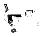
- FIGS. 4–8 are various views showing the handle assembly of the suturing instrument shown in FIGS. 1–3 ;
- FIGS. 9–21 are various views showing the handle cartridge assembly of the handle assembly shown in FIGS. 4–8 ;
- FIGS. 22–24 are various views showing the battery pin assembly of the handle assembly shown in FIGS. 4–8 ;
- FIGS. 25–38 are various views showing the cannula assembly of the suturing instrument shown in FIGS. 1–3 ;
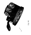
- FIGS. 39–48 are various views showing the wire drive assembly of the suturing instrument shown in FIGS. 1–3 ;
- FIGS. 49–54 are various views showing the wire supply cartridge of the suturing instrument shown in FIGS. 1–3 ;
- FIGS. 55 and 56 are various views of the shroud assembly of the suturing instrument shown in FIGS. 1–3 ;
- FIGS. 57–66 show various steps in a suturing operation conducted with the suturing instrument shown in FIGS. 1–3 ;
- FIG. 67 is a sectional view showing one possible construction for the suturing instrument's first jaw 206 and its associated cutting bar;
- FIG. 68 is a side view showing a piece of wire cut with the apparatus shown in FIG. 67 ;
- FIG. 69 is a sectional view showing another possible fixed construction for the suturing instrument's first jaw 206 and its associated cutting bar.
- FIG. 70 is a side view showing a piece of wire cut with the apparatus shown in FIG. 69 .
- Suturing instrument 2 which comprises a preferred embodiment of the present invention.
- Suturing instrument 2 generally comprises a handle assembly 100 , a cannula assembly 200 , a wire drive assembly 300 , a wire supply cartridge 400 and a shroud assembly 500 , as will hereinafter be described in further detail.
- cannula assembly 200 comprises a shaft 202 , an end effector 204 comprising a first jaw 206 and a second jaw 208 , a jaw closing actuator 210 , a wire advance button 212 , a left rotation button 214 , a right rotation button 216 ( FIG. 3 ), and a wire cutting actuator 218 , as will also hereinafter be described in further detail.
- the suturing instrument's end effector 204 is positioned adjacent to the tissue which is to be sutured and, using jaw closing actuator 210 , jaws 206 and 208 are brought together around the tissue which is to be sutured.
- wire advance button 212 is activated, causing wire drive assembly 300 to draw suture wire out of wire supply cartridge 400 and push the suture wire distally through cannula assembly 200 to end effector 204 .
- the suture wire is driven from first jaw 206 to second jaw 208 with sufficient force to penetrate the tissue placed between the two jaws, and the suture wire is permitted to pass through second jaw 208 .
- Jaws 206 and 208 are then separated and moved away from the tissue, as more suture wire is payed out, leaving the suture wire extending from the subject tissue to each of the two jaws.
- End effector 204 (together with wire supply cartridge 400 ) may then be rotated with respect to the tissue by actuating either left rotation button 214 or right rotation button 216 ( FIG. 3 ). This causes the portions of the suture wire that extend from the tissue to be twisted about one another so as to form a closed loop extending through the tissue. It will be appreciated that the size of this closed loop may be adjustably reduced by increasing the degree of twisting in the wire.
- the twisted loop of suture wire may then be cut off, at end effector 204 , from the remaining suture wire that extends back through the suturing instrument. Such cutting may be effected by actuating wire cutting actuator 218 .
- wire supply cartridge 400 may be supplied separately from suturing instrument 2 , with wire supply cartridge 400 being loaded into suturing instrument 2 prior to commencing a suturing operation. As will also be discussed in further detail below, wire supply cartridge 400 may be disposable, such that the cartridge may be discarded after use.
- handle assembly 100 comprises a housing 102 , a battery door 104 , a handle cartridge assembly 106 , a battery pin assembly 108 and a rear cover assembly 110 .
- Housing 102 is shown in greater detail in FIG. 8 .
- Housing 102 defines a main compartment 112 , a battery pin compartment 114 and a battery compartment 116 .
- a chin pin 118 is secured in the proximal end of housing 102 and extends proximally therefrom. Chin pin 118 is used to secure shroud assembly 500 ( FIG. 2 ) to housing 102 , as will hereinafter be discussed in further detail.
- Battery door 104 selectively closes off battery compartment 116 .
- battery door 104 is hingedly connected to housing 102 by a pin 120 ( FIG. 8 ), and includes a door latch 122 ( FIG. 8 ) for selectively releasing and locking the battery door.
- Handle cartridge assembly 106 ( FIG. 7 ) is shown in greater detail in FIGS. 9–13 .
- Handle cartridge assembly 106 generally comprises a housing 123 , a shaft 124 ( FIG. 13 ), a gear and clutch assembly 126 , a clutch assembly 128 , a motor 130 and a switch 132 .
- Housing 123 includes a first cavity 134 ( FIG. 10 ) for receiving shaft 124 and portions of gear and clutch assembly 126 and portions of clutch assembly 128 , and a second cavity 136 ( FIG. 10 ) for receiving portions of motor 130 and switch 132 .
- Housing 132 of handle cartridge assembly 106 also includes a seal 138 ( FIG. 10 ) for sealing handle cartridge assembly 106 within main compartment 112 ( FIG. 8 ) of handle 102 .
- Shaft 124 ( FIG. 13 ) is selectively coupled to motor 130 via gear and clutch assembly 126 , and is selectively coupled to cannula assembly 200 via clutch assembly 128 , as will hereinafter be discussed in further detail.
- Gear and clutch assembly 126 is shown in greater detail in FIGS. 14–16 .
- Gear and clutch assembly 126 comprises a hub 139 , a large gear 140 and a smaller gear 142 mounted on hub 139 , a seal 144 , a second hub 146 , and a one-way clutch 148 received within second hub 146 .
- gear and clutch assembly 126 is press fit onto shaft 124 ( FIG. 13 ) and motor 130 is used to turn large gear 140 clockwise (as viewed from the left hand side of FIG. 13 )
- hubs 139 and 146 and smaller gear 142 will also turn clockwise (as viewed from the left hand side of FIG. 13 ).
- Clutch assembly 128 ( FIG. 13 ) is shown in greater detail in FIG. 17 .
- Clutch assembly 128 comprises a hub 150 , a one-way clutch 152 received within hub 150 , a seal 154 and a second hub 156 .
- clutch assembly 128 will permit shaft 124 to rotate clockwise (as viewed from the left hand side of FIG. 13 ) but will prevent shaft 124 from rotating counterclockwise (as viewed from the left hand side of FIG. 13 ).
- shaft 124 By mounting gear and clutch assembly 126 and clutch assembly 128 to shaft 124 , and by configuring one-way clutch 148 and one-way clutch 152 for opposing rotation, shaft 124 can be rotated clockwise (as viewed from the left hand side of FIG. 13 ) by clockwise rotation (as viewed from left hand side of FIG. 13 ) of motor 130 . At the same time, however, counterclockwise rotation (as viewed from left hand side of FIG. 13 ) of motor 130 will not result in any counterclockwise rotation (as viewed from the left hand side of FIG. 13 ) of shaft 124 due to the arrangement of one-way clutch 152 .
- Switch 132 ( FIG. 13 ) is shown in greater detail in FIGS. 18–21 .
- Switch 132 comprises a front 158 , a first pair of electrical contacts 160 A and 160 B, a body 162 , a second pair of electrical contacts 164 A and 164 B and a back 166 , with all of the foregoing held together as a single unit by a pair of screws 168 .
- Switch 132 serves to selectively connect a pair of battery poles 170 A and 170 B ( FIG. 21 ), forming part of battery pin assembly 108 , to a pair of motor poles 172 A and 172 B.
- switch 132 is normally disposed so that its electrical contact 164 A is in engagement with battery pole 170 A, and its electrical contact 164 B is in engagement with battery pole 170 B, with motor pole 172 A extending through an opening 174 B ( FIG. 21 ) in electrical contact 164 B and with motor pole 172 B extending through an opening 174 A in electrical contact 164 A.
- switch 132 is normally disposed so that its electrical contact 164 A is in engagement with battery pole 170 A, and its electrical contact 164 B is in engagement with battery pole 170 B, with motor pole 172 A extending through an opening 174 B ( FIG. 21 ) in electrical contact 164 B and with motor pole 172 B extending through an opening 174 A in electrical contact 164 A.
- motor 130 can be energized with a first polarity, such that it will rotate counterclockwise (as viewed from the left hand side of FIG. 13 ) and thereby drive shaft 124 clockwise (as viewed from the left hand side of FIG. 13 ).
- motor 130 can be energized with a second opposite polarity, such that it will rotate clockwise (as viewed from the left hand side of FIG. 13 ).
- this clockwise rotation of motor 130 will not cause any rotation of shaft 124 , due to the configuration of one-way clutches 148 and 152 , which permit shaft 124 to rotate in only a clockwise direction (as viewed from the left hand side of FIG.
- Battery pin assembly 108 is shown in greater detail in FIGS. 22–24 .
- Battery pin assembly 108 comprises a body 176 which supports the aforementioned two battery poles 170 A and 170 B, and a pair of battery contacts 178 A and 178 B for engagement with a battery (not shown) housed in battery compartment 116 ( FIG. 8 ).
- Cannula assembly 200 ( FIG. 2 ) is shown in greater detail in FIGS. 25–38 .
- cannula assembly 200 ( FIG. 2 ) comprises shaft 202 , end effector 204 comprising first jaw 206 and second jaw 208 , jaw closing actuator 210 , wire advance button 212 , left rotation button 214 , right rotation button 216 and wire cutting actuator 216 .
- Cannula assembly 200 also includes a housing 220 ( FIG. 25 ) which acts as a support for the aforementioned elements.
- Shaft 202 is shown in greater detail in FIGS. 28–31 .
- Shaft 202 comprises a body 222 ( FIG. 29 ) which has a tubular proximal end 224 and a trifurcated distal end 226 .
- a jaw linkage 228 extends through the distal end of tubular proximal end 224 and alongside (i.e., within one of the grooves) of trifurcated distal end 226 .
- Jaw linkage 228 is connected at its distal end to first jaw 206 and second jaw 208 as will hereinafter be described in further detail, and is connected at its proximal end to an internal mount 230 ( FIG. 33 ).
- a pin 232 ( FIG. 31 ) extends through a pair of slots 234 in tubular proximal end 224 and connects internal mount 230 ( FIG. 33 ) to an external mount 236 .
- a cutter bar linkage 238 ( FIG. 29 ) also extends through the distal end of tubular proximal end 224 and alongside trifurcated distal end 226 .
- Cutter bar linkage 238 is connected as its distal end to a cutter bar 240 via superelastic Nitinol wire flexible coupling ( FIG. 34 ), and is connected at its proximal end to an internal mount 242 ( FIG. 33 ).
- a pin 244 ( FIG. 31 ) extends through a pair of slots 246 in tubular proximal end 224 and connects internal mount 242 to an external mount 248 .
- axial movement of external mount 248 will result in axial movement of cutter bar linkage 238 , whereby to advance and retract cutter bar 240 , as will hereinafter be discussed in further detail.
- a hollow wire guide 250 ( FIG. 38 ) which terminates, at its proximal end, in a mount 252 .
- the distal end of mount 252 is received by the proximal end of tubular proximal end 224 .
- the distal end of hollow wire guide 250 is received in a channel 254 ( FIG. 35 ) formed in first jaw 206 , as will hereinafter be discussed in further detail.
- Channel 254 communicates with a suture wire guide 256 formed in first jaw 206 , whereby suture wire emerging from hollow wire guide 250 will enter suture wire guide 256 .
- Suture wire guide 256 is configured so that when first jaw 206 and second jaw 208 are closed, suture wire guide 256 will receive suture wire advancing parallel to the axis of shaft 202 and redirect it, substantially perpendicularly, toward second jaw 208 .
- Wire guide 256 is configured to work with a range of different jaw openings, i.e., wire guide 256 is configured to work successfully regardless of whether the jaws are closed on relatively thin tissue or relatively thick tissue.
- Preferably wire guide 256 has radius of 0.125 inches.
- first jaw 206 may include a removable cover 259 ( FIG. 37 ) so as to provide access to the interior of first jaw 206 .
- Second jaw 208 has an opening 257 ( FIG. 36 ) formed therein to receive the wire exiting first jaw 206 .
- jaw closing actuator 210 is connected to external mount 236 such that depressing actuator 210 toward handle assembly 100 will cause external mount 236 to move proximally, whereby to move jaw linkage 228 proximally, and whereby to cause first jaw 206 and second jaw 208 to close toward one another.
- a coil spring 258 FIG. 27
- external mount 236 will move distally, whereby to move jaw linkage 228 distally, and whereby to cause first jaw 206 and second jaw 208 to separate from one another.
- wire cutting actuator 218 is connected to external mount 248 such that depressing wire cutting actuator 218 toward handle assembly 100 will cause external mount 248 to move distally, whereby to move cutter bar linkage 238 distally and whereby to cause cutter bar 240 to move distally within a passageway 260 ( FIG. 35 ) formed in first jaw 206 .
- cutter bar passageway intersects suture wire guideway 256 near the distal end of first jaw 206 , such that cutter bar 240 can sever a length of suture wire extending through suture wire guideway 256 , as will hereinafter be discussed in greater detail.
- a coil spring 262 ( FIG. 27 ) will cause external mount 248 to move proximally, whereby to move cutter bar linkage 238 proximally and whereby to cause cutter bar 240 to move proximally within passageway 260 .
- external mounts 236 and 248 permit the shaft to rotate for wire twisting purposes while simultaneously permitting axial motion for jaw actuation and cutter bar actuation.
- wire advance button 212 is connected to a pair of push rods 262 ( FIG. 27 ).
- Push rods 262 are arranged to that when cannula assembly 200 is mounted to handle assembly 100 and wire advance button 212 is depressed (i.e., pushed toward handle assembly 100 ), push rods 262 will engage front 158 of switch 132 , whereby to drive front 158 proximally, whereby to energize motor 130 with the aforementioned second polarity, such that motor 130 will rotate clockwise (as viewed from the left hand side of FIG. 13 ). Such motor rotation will cause suture wire to be advanced out of the distal end of suturing instrument 2 , as will hereinafter be discussed in further detail.
- proximal ends 264 , 266 ( FIG. 25 ) of left rotation button 214 and right rotation button 216 are exposed at the proximal end of cannula assembly 100 , whereby they may engage fingers 268 , 270 ( FIG. 19 ), respectively, formed on front 158 of switch 132 .
- the various parts are arranged so that engagement of left rotation button 214 or right rotation button 216 will result in rotation of front 158 of switch 132 , which will in turn result in motor 130 being energized with the aforementioned first polarity, such that motor 130 will rotate counterclockwise (as viewed from the left hand side of FIG. 13 ) and whereby to drive shaft 124 clockwise (as viewed from the left hand side of FIG. 13 ).
- wire drive assembly 300 comprises a body 302 ( FIG. 44 ), a base plate 304 fastened to body 302 by a pair of screws 306 , a spur gear 308 connected to a miter gear 310 via a shaft 312 , a fixed block 314 mounted on a rod 316 , a screw 318 securing rod 316 to body 302 , a second miter gear 320 connected to a drive shaft roller 322 and a spur gear 324 via an axle 326 passing through fixed block 314 , a second drive shaft roller 328 connected to a spur gear 330 via an axle 332 , a movable block 334 slidably mounted on rod 316 , a block 336 , spring 338 , washer 340 and screw 342 for biasing movable block 334 into engagement with fixed block 314 , and a lever 344 and arm 346 for manually forcing movable block 334 away from fixed block 314 .
- Wire drive assembly 300 also comprises
- cannula lock lever 348 can be pressed inwardly, against the force of spring 352 , whereby to align enlarged portion 354 of keyway 350 with notches 272 ( FIG. 38 ) of mount 250 , and thereafter released, so as to lock the cannula and wire drive assembly 300 together, as will hereinafter be discussed in further detail.
- wave washers WW 1 and WW 2 bias spur gears 324 and 330 , respectively, away from fixed block 314 and movable block 334 , which, via axles 325 and 332 respectively, urge drive wheels 322 and 328 against body 302 , whereby to keep wheels 322 and 328 aligned and in a fixed relative position.
- Each drive wheel and axle assembly is machined (turned) from a single, continuous piece of metal, using the same tool setup, so that the alignment of both is immune from the inaccuracies that would occur if they were turned at different occasions and assembled using holes and holding means.
- peripheral grooves may be formed in wheels 322 and 328 . Such grooves provide a seat for the wire being driven and help increase the surface area contact between the wheels and the wire.
- wire supply cartridge 400 generally comprises a spool housing 402 ( FIG. 50 ), a wire spool 404 , a spool retainer spring 406 , a spool cover 408 , a molded tube support 410 holding a wire support tube 412 and a PEEK wire guide tube 414 .
- a length of wire 416 extends from spool 404 , through molded tube support 410 and wire support tube 412 , and through PEEK wire guide tube 414 .
- a supply coil of suture wire 416 (comprising wire formed of metal or any other suitable material having the required flexibility and stiffness) may be supplied in the base of cartridge 400 and is fed into molded tube support 410 , where it enters wire support unit 412 before entering PEEK wire guide tube 414 .
- PEEK wire guide tube 414 surrounds suture wire 416 , from wire support unit 412 to the distal end of suturing instrument 2 where, with the distal end of PEEK tube received in channel 254 ( FIG. 35 ), the suture wire enters suture wire guide 256 in first jaw 206 .
- PEEK wire guide tube 414 ensures that suture wire 416 does not bend or buckle as the suture wire is pushed through handle assembly 100 and cannula assembly 200 . More particularly, PEEK wire guide tube 414 preferably forms a sufficiently close sliding fit with suture wire 416 such that suture wire 416 cannot bend or buckle as the suture wire is advanced through suturing instrument 2 . At the same time, PEEK wire guide tube 414 is also formed so as to present a minimum of friction to suture wire 416 as the suture wire is advanced through the instrument. In addition, PEEK wire guide tube 414 also provides a flexible support as the suture wire moves from the shaft to the upper jaw, which pivots relative to the longitudinal axis of the shaft. The foregoing characteristics are important, inasmuch as suture wire 416 is extremely thin and flexible and highly susceptible to bending or buckling in the absence of some sort of lateral support.
- PEEK wire guide tube 414 might have an inside diameter of 0.008 inch and an outside diameter of 0.016 inch.
- PEEK wire guide tube 414 is preferably formed out of polyetheretherketone; however, it may alternatively be formed out of polytetrafluoroethylene (PTFE) or some other relatively lubricious material.
- PTFE polytetrafluoroethylene
- the interior of PEEK wire guide tube 414 may be coated with a lubricant so as to facilitate closely-supported, low-friction passage of the suture wire through the wire guide.
- suture wire 416 may comprise 316 LVM stainless steel having a tensile strength of 168,000 psi.
- Wire support unit 412 and its surrounding molded tube support 410 have aligned openings 418 , 420 ( FIG. 52 ) respectively, on opposite sides thereof. Openings 418 , 420 expose a portion of suture wire 416 so that rollers 322 , 328 ( FIG. 44 ) may contact suture wire 416 and urge the suture wire forward toward the distal end of suturing instrument 2 , as will hereinafter be discussed in further detail.
- Wire supply cartridge 400 may be attached to wire drive assembly 300 by actuating lever 344 so as to force movable block 334 away from fixed block 314 and thereby separate roller 328 .
- PEEK wire guide tube 414 may be inserted into the interior of wire guide 250 and molded tube support 410 may be inserted between rollers 322 and 328 such that rollers 322 and 328 contact either side of suture wire 416 through openings 420 , 418 formed in either side of molded tube support 410 and wire support unit 412 , respectively.
- shroud 500 comprises a body 502 having a recess 504 and a locking finger 506 .
- Locking finger 506 selectively engages chin pin 118 for locking and unlocking shroud 500 relative to handle assembly 100 .
- Suturing instrument 2 may be used to apply wire suture 416 to a subject so as to effect a desired suturing operation.
- suturing instrument 2 may be used to suture together two portions 600 , 602 of a subject which is to be sutured.
- portions 600 , 602 might comprise two sections of severed tissue which need to be re-attached to one another, or two pieces of previously unattached tissue which need to be attached to one another.
- one or the other of the portions 600 , 602 might also comprise artificial mesh or some other object being attached to tissue, etc.
- portions 600 , 602 might be located relatively deep within a patient, and might be accessed during an endoscopic or a so-called “minimally invasive”, or a so-called “closed surgery”, procedure; however, in other circumstances, portions 600 , 602 might be accessed during a conventional, or so-called “open surgery”, procedure.
- This later situation might include procedures done at the outer surface of the patient's body, i.e., where portions 600 , 602 comprise surface subjects.
- suturing instrument 2 is initially prepared for use by installing a battery into handle assembly 100 , if a battery is not already installed, and by installing wire supply cartridge 400 into the suturing instrument, if a cartridge 400 is not yet installed.
- wire supply cartridge 30 is installed in suturing instrument 2 by (1) removing shroud 500 , (2) moving the wire drive assembly's release lever 344 to its open position, so as to move rollers 322 and 328 apart and thereby expose the distal end of mount 252 ; (3) passing the distal end of the cartridge (i.e., the distal end of PEEK wire guide tube 414 ) through cannula assembly 200 until the distal end of PEEK wire guide tube 414 is in communication with the suture wire guide 256 formed in first jaw portion 206 , at which point the cartridge's molded tube support 410 will be positioned intermediate rollers 322 and 328 ; and (4) moving the wire drive assembly's release lever 344 back to its closed position, so as to cause rollers 322
- suturing instrument 2 will be ready for use, with its first jaw 206 and second jaw 208 being open, and with its cutter bar 240 being in its retracted (i.e., non-cutting) position.
- suturing instrument 2 has its jaws 206 , 208 placed in their “closed” position) by pulling jaw closing actuator 210 toward handle assembly 100 , and then the distal end of suturing instrument 2 is moved adjacent to subject portions 600 , 602 ( FIG. 57 ).
- such positioning will generally involve moving the distal end of the suturing instrument through a cannula and into an interior body cavity; however, it is also envisioned that one might move the distal end of the suturing instrument directly into an otherwise-accessible body cavity, e.g., directly into the colon or esophagus, etc.
- such positioning might involve positioning the distal end of the suturing instrument adjacent to more readily accessible subject portions 600 , 602 .
- jaw closing actuator 210 is released, such that biasing spring 258 ( FIG. 27 ) will cause jaws 206 , 208 to move away from one another ( FIG. 58 ). Then the distal end of suturing instrument 2 is moved so that its jaws 206 , 208 straddle subject portions 600 , 602 , and then jaw closing actuator 210 is actuated again, by pulling jaw closing actuator 210 toward handle assembly 100 , so as to close jaws 206 , 208 against one another, whereby to capture subject portions 600 , 602 ( FIG. 59 ).
- wire advance button 212 is activated so as to cause suture wire 416 to be driven forward, out of the distal end of wire guide 256 , through subject portions 600 , 602 , and finally through opening 257 ( FIG. 36 ) formed in second jaw 208 .
- Suture wire 416 is preferably advanced so that a length 416 A of wire 416 extends approximately 1 centimeter out of the bottom end of second jaw 208 ( FIG. 59 ).
- the first jaw's wire guide 256 will support the thin suture wire so as to enable the suture wire to penetrate subject portions 600 , 602 .
- wire guide 256 is configured to pass the wire to second jaw 208 regardless of whether the jaws are closed on relatively thin tissue or relatively thick tissue.
- jaw closing actuator 210 is released so as to permit jaws 206 , 208 to return to their “open” position, and then wire advance button 212 is used to pay out additional suture wire 416 as the distal end of suturing instrument 2 is stepped back (e.g., by about a centimeter or so) from subject portions 600 , 602 ( FIG. 60 ).
- jaw closing actuator 210 is used to move jaws 206 , 208 back into engagement with one another once more ( FIG. 61 ).
- left rotation button 214 or right rotation button 216 , is used to rotate shaft 202 and hence end effector 204 .
- This causes suture wire 416 to twist on itself, initially creating a relatively large loop 417 ( FIG. 61 ) of suture wire 416 extending from subject portions 600 , 602 toward suturing instrument 2 .
- left rotation button 214 and/or right rotation button 216 is used to rotate shaft 202 (and hence end effector 204 ) more and more, the loop 417 of suture material will progressively close down ( FIG. 62 ) so as to form a tight binder for subject portions 600 , 602 .
- suture wire 416 is preferably carefully selected with respect to its flexibility relative to the strength of subject portions 600 , 602 .
- suture wire 416 is chosen so as to have a flexibility such that the suture wire will twist, and loop 417 will close down, before subject portions 600 , 602 will undergo substantial deformation and/or tearing.
- suture wire 416 is also chosen to have an adequate columnar strength, whereby to permit it to be driven through the tool and across the tissue.
- wire cutting actuator 218 is released, allowing biasing spring 262 to return cutting bar 240 to return to its proximal position, and then jaw closing actuator 210 is released, allowing jaws 206 and 208 to move away from one another. Suturing instrument 2 may then be removed from subject portions 600 , 602 , which action will pull wire length 416 A from second jaw 208 ( FIG. 65 ).
- the deployed suture wire 416 may then be pressed down flat against subject portions 600 , 602 or rounded into a ball, or otherwise operated upon, or portions cut away, etc. so as to reduce the profile of, or reduce the tendency to snag on, the deployed suture wire ( FIG. 66 ).
- jaw opening and closing, wire length and the degree of wire twisting are all variable and adjustable by the operator according to the particular surgical application involved.
- suturing instrument 2 will have application in a broad range of different suturing operations. More particularly, it will be appreciated that suturing instrument 2 will have application in both “open” and “closed” surgical procedures, with the former including, but not limited to, large entry procedures, relatively shallow procedures, and surface procedures; and with the latter including, but not limited to, surgical procedures where access is gained to an interior structure through the use of a cannula, and surgical procedures where access is gained directly to an internal body cavity without the use of a cannula, e.g., such as a procedure conducted within the colon or the esophagus.
- suturing instrument 2 will have application where two portions of tissue must be attached to one another (e.g., where two severed pieces of tissue must be re-attached to one another, or where two separate pieces of tissue must be attached to one another, or where two sections of a single piece of tissue must be approximated to one another), and where an object must be attached to the patient (e.g., where surgical mesh must be attached to the patient's abdominal wall during hernia repair surgery, etc.).
- suturing instrument 2 will have particular application in the areas of general laparoscopic surgery, general thoracic surgery, cardiac surgery, general intestinal surgery, vascular surgery, skin surgery and plastic surgery.
- suture wire 416 will be cut with a relatively flat leading end 416 B ( FIG. 68 ).
- suture wire 416 can help open the subject for the following portion of the suture wire.
- suture wire can help the suture wire penetrate the subject with a substantially straight path, so that the suture wire will reliably enter the second jaw's opening 257 .
- suturing instrument 2 it is also possible to use suturing instrument 2 to ligate a subject rather than to pass a suture through the subject.
- suturing instrument 2 might be used to ligate a blood vessel or cystic duct with suture wire 416 .
- suturing. instrument 2 is deployed so that suture wire 416 will pass around the far side of the subject, rather than through the subject as in the case of the suturing operation of the type described above.
- first and second jaws 206 , 208 are first opened relative to one another. Then suturing instrument 2 is positioned about the subject so that when the two jaws are thereafter closed toward one another, the first jaw's guide channel 256 and the second jaw's opening 257 will both lie on the far side of the subject. The two jaws are then closed against one another, and suture wire 416 is passed from first jaw 206 to second jaw 208 , i.e., around the far side of the subject. The two jaws are then opened, and suture wire 416 is payed out as the instrument is stepped back from the subject. Then the two jaws are closed again.
- the shaft of the instrument is then rotated so as to form, and then close down, the ligating loop.
- cutting bar 240 is activated so as to cut the ligating loop from the remainder of the suture wire still in the tool, the two jaw members are opened, and the instrument is withdrawn from the surgical site.
- the deployed suture wire 416 may then be pressed down flat against the subject, or rounded into a ball, or otherwise operated upon, or portions cut away, etc. so as to reduce the profile of, or reduce the tendency to snag on, the deployed suture wire.
- first and second jaws 206 , 208 might be formed with a greater longitudinal length so as to facilitate passing the suture wire around the far side of the subject.
- one or both of the jaw members might be formed with a recess, intermediate their length, for accommodating the subject, whereby to prevent compressing the subject when the two jaw members are moved into engagement with one another.
- Suture wire 416 may comprise a wire formed out of a metal or any other suitable material having the required flexibility and stiffness.
- suture wire 416 may comprise stainless steel, titanium, tantalum, etc.
- suture wire 416 may also be coated with various active agents.
- suture wire 416 may be coated with an anti-inflammatory agent, or an anti-coagulant agent, or an antibiotic, or a radioactive agent, etc.
- the instrument may also be used to anchor a guide wire into tissue for the purposes of subsequently delivering an object to that tissue anchor point.
- the jaws would grasp tissue at the desired anchor point in the tissue, drive wire through it and twist the wire ends together.
- the user would drive wire, with the jaws open, as the instrument was withdrawn out of the surgical area.
- the proximal end of this length of wire is then secured.
- the wire could be cut, leaving an open proximal end over which various devices could be pushed to the tissue site (e.g. pH sensors, gastric motility leads, cardiac pacing leads, drug delivery catheters, drug factories, and micro electromechanical “MEM systems,” etc.)
Abstract
Description
Claims (37)
Priority Applications (1)
| Application Number | Priority Date | Filing Date | Title |
|---|---|---|---|
| US10/202,530 US7011668B2 (en) | 2001-07-23 | 2002-07-23 | Surgical suturing instrument and method of use |
Applications Claiming Priority (3)
| Application Number | Priority Date | Filing Date | Title |
|---|---|---|---|
| US30725501P | 2001-07-23 | 2001-07-23 | |
| US10/014,991 US20020128666A1 (en) | 1998-08-27 | 2001-12-11 | Surgical suturing instrument and method of use |
| US10/202,530 US7011668B2 (en) | 2001-07-23 | 2002-07-23 | Surgical suturing instrument and method of use |
Related Parent Applications (1)
| Application Number | Title | Priority Date | Filing Date |
|---|---|---|---|
| US10/014,991 Continuation-In-Part US20020128666A1 (en) | 1998-08-27 | 2001-12-11 | Surgical suturing instrument and method of use |
Publications (2)
| Publication Number | Publication Date |
|---|---|
| US20030105475A1 US20030105475A1 (en) | 2003-06-05 |
| US7011668B2 true US7011668B2 (en) | 2006-03-14 |
Family
ID=26686807
Family Applications (1)
| Application Number | Title | Priority Date | Filing Date |
|---|---|---|---|
| US10/202,530 Expired - Lifetime US7011668B2 (en) | 2001-07-23 | 2002-07-23 | Surgical suturing instrument and method of use |
Country Status (1)
| Country | Link |
|---|---|
| US (1) | US7011668B2 (en) |
Cited By (23)
| Publication number | Priority date | Publication date | Assignee | Title |
|---|---|---|---|---|
| US20090259233A1 (en) * | 2008-04-11 | 2009-10-15 | Michael Bogart | Deployment System For Surgical Suture |
| US20090312773A1 (en) * | 2008-06-13 | 2009-12-17 | Ramiro Cabrera | Endoscopic stitching devices |
| US20100217282A1 (en) * | 2006-10-05 | 2010-08-26 | Tyco Healthcare Group Lp | Flexible endoscopic stitching devices |
| US20100218967A1 (en) * | 2009-02-27 | 2010-09-02 | Andreas Stihl Ag & Co. Kg | Electric Power Tool with Battery Pack |
| US20100241142A1 (en) * | 2009-03-23 | 2010-09-23 | Linvatec Corporation | Suture passing apparatus and method |
| US20110040308A1 (en) * | 2008-06-13 | 2011-02-17 | Ramiro Cabrera | Endoscopic Stitching Devices |
| US20110082476A1 (en) * | 2009-10-06 | 2011-04-07 | Tyco Healthcare Group Lp | Handle Assembly for Endoscopic Suturing Device |
| US8105355B2 (en) | 2006-05-18 | 2012-01-31 | C.R. Bard, Inc. | Suture lock fastening device |
| US8328061B2 (en) | 2010-02-02 | 2012-12-11 | Covidien Lp | Surgical instrument for joining tissue |
| WO2013046115A1 (en) | 2011-09-26 | 2013-04-04 | Novolap Medical Ltd. | Surgical fastening device and method |
| US8454631B2 (en) | 2006-10-05 | 2013-06-04 | Covidien Lp | Axial stitching devices |
| USD708746S1 (en) | 2009-06-10 | 2014-07-08 | Covidien Lp | Handle for surgical device |
| US8968340B2 (en) | 2011-02-23 | 2015-03-03 | Covidien Lp | Single actuating jaw flexible endolumenal stitching device |
| US9125644B2 (en) | 2011-08-14 | 2015-09-08 | SafePath Medical, Inc. | Apparatus and method for suturing tissue |
| US9326765B2 (en) | 2012-02-22 | 2016-05-03 | SafePath Medical, Inc. | Suturing device having an internal suture dispensing mechanism |
| US9468434B2 (en) | 2014-06-03 | 2016-10-18 | Covidien Lp | Stitching end effector |
| US9554793B2 (en) | 2013-03-16 | 2017-01-31 | SafePath Medical, Inc. | Means and methods for suturing tissue |
| US9743924B2 (en) | 2014-05-17 | 2017-08-29 | SafePath Medical, Inc. | Systems and methods for suturing tissue |
| US10092286B2 (en) | 2015-05-27 | 2018-10-09 | Covidien Lp | Suturing loading unit |
| US10470757B2 (en) | 2016-03-02 | 2019-11-12 | Stryker Corporation | Suture passing instruments and methods |
| US10542970B2 (en) | 2016-05-31 | 2020-01-28 | Covidien Lp | Endoscopic stitching device |
| US10945723B2 (en) | 2016-11-17 | 2021-03-16 | SafePath Medical, Inc. | Systems and methods for suturing tissue |
| US11197665B2 (en) | 2018-08-06 | 2021-12-14 | Covidien Lp | Needle reload device for use with endostitch device |
Families Citing this family (167)
| Publication number | Priority date | Publication date | Assignee | Title |
|---|---|---|---|---|
| US6527785B2 (en) * | 1999-08-03 | 2003-03-04 | Onux Medical, Inc. | Surgical suturing instrument and method of use |
| US6679895B1 (en) * | 1999-11-05 | 2004-01-20 | Onux Medical, Inc. | Apparatus and method for placing suture wires into tissue for the approximation and tensioning of tissue |
| CA2426552C (en) | 2000-10-20 | 2009-07-14 | Onux Medical, Inc. | Surgical suturing instrument and method of use |
| EP1406545B1 (en) | 2001-06-14 | 2015-10-28 | Endoevolution, Llc | Apparatus and method for surgical suturing with thread management |
| EP1487352A4 (en) * | 2002-03-25 | 2006-07-12 | Dvl Acquisition Sub Inc | Surgical suturing instrument and method of use |
| JP2005525866A (en) * | 2002-05-17 | 2005-09-02 | オーナックス・メディカル・インコーポレーテッド | Surgical suture instrument and method of use thereof |
| US20070084897A1 (en) | 2003-05-20 | 2007-04-19 | Shelton Frederick E Iv | Articulating surgical stapling instrument incorporating a two-piece e-beam firing mechanism |
| US9060770B2 (en) | 2003-05-20 | 2015-06-23 | Ethicon Endo-Surgery, Inc. | Robotically-driven surgical instrument with E-beam driver |
| US11896225B2 (en) | 2004-07-28 | 2024-02-13 | Cilag Gmbh International | Staple cartridge comprising a pan |
| US8123764B2 (en) | 2004-09-20 | 2012-02-28 | Endoevolution, Llc | Apparatus and method for minimally invasive suturing |
| US9775600B2 (en) | 2010-10-01 | 2017-10-03 | Endoevolution, Llc | Devices and methods for minimally invasive suturing |
| US7976555B2 (en) | 2008-07-17 | 2011-07-12 | Endoevolution, Llc | Apparatus and method for minimally invasive suturing |
| US11246590B2 (en) | 2005-08-31 | 2022-02-15 | Cilag Gmbh International | Staple cartridge including staple drivers having different unfired heights |
| US7669746B2 (en) | 2005-08-31 | 2010-03-02 | Ethicon Endo-Surgery, Inc. | Staple cartridges for forming staples having differing formed staple heights |
| US10159482B2 (en) | 2005-08-31 | 2018-12-25 | Ethicon Llc | Fastener cartridge assembly comprising a fixed anvil and different staple heights |
| US20070106317A1 (en) | 2005-11-09 | 2007-05-10 | Shelton Frederick E Iv | Hydraulically and electrically actuated articulation joints for surgical instruments |
| AU2007210030B2 (en) | 2006-01-27 | 2013-09-26 | Intuitive Surgical Operations, Inc. | Apparatus and method for tissue closure |
| US11793518B2 (en) | 2006-01-31 | 2023-10-24 | Cilag Gmbh International | Powered surgical instruments with firing system lockout arrangements |
| US7845537B2 (en) | 2006-01-31 | 2010-12-07 | Ethicon Endo-Surgery, Inc. | Surgical instrument having recording capabilities |
| US8820603B2 (en) | 2006-01-31 | 2014-09-02 | Ethicon Endo-Surgery, Inc. | Accessing data stored in a memory of a surgical instrument |
| US20110290856A1 (en) | 2006-01-31 | 2011-12-01 | Ethicon Endo-Surgery, Inc. | Robotically-controlled surgical instrument with force-feedback capabilities |
| US8186555B2 (en) | 2006-01-31 | 2012-05-29 | Ethicon Endo-Surgery, Inc. | Motor-driven surgical cutting and fastening instrument with mechanical closure system |
| US8708213B2 (en) | 2006-01-31 | 2014-04-29 | Ethicon Endo-Surgery, Inc. | Surgical instrument having a feedback system |
| US20120292367A1 (en) | 2006-01-31 | 2012-11-22 | Ethicon Endo-Surgery, Inc. | Robotically-controlled end effector |
| US10568652B2 (en) | 2006-09-29 | 2020-02-25 | Ethicon Llc | Surgical staples having attached drivers of different heights and stapling instruments for deploying the same |
| US20080140091A1 (en) * | 2006-12-12 | 2008-06-12 | Dedeyne Patrick G | Minimally invasive suture-based repair of soft tissue |
| US8684253B2 (en) | 2007-01-10 | 2014-04-01 | Ethicon Endo-Surgery, Inc. | Surgical instrument with wireless communication between a control unit of a robotic system and remote sensor |
| US8540128B2 (en) | 2007-01-11 | 2013-09-24 | Ethicon Endo-Surgery, Inc. | Surgical stapling device with a curved end effector |
| US8006885B2 (en) * | 2007-04-09 | 2011-08-30 | Tyco Healthcare Group Lp | Surgical stapling apparatus with powered retraction |
| US8931682B2 (en) | 2007-06-04 | 2015-01-13 | Ethicon Endo-Surgery, Inc. | Robotically-controlled shaft based rotary drive systems for surgical instruments |
| US11857181B2 (en) | 2007-06-04 | 2024-01-02 | Cilag Gmbh International | Robotically-controlled shaft based rotary drive systems for surgical instruments |
| US11849941B2 (en) | 2007-06-29 | 2023-12-26 | Cilag Gmbh International | Staple cartridge having staple cavities extending at a transverse angle relative to a longitudinal cartridge axis |
| FR2924917B1 (en) * | 2007-12-13 | 2011-02-11 | Microval | APPARATUS FOR INSTALLING SUTURE SPIERS RESULTING FROM A SHAPE MEMORY METAL WIRE. |
| US8636736B2 (en) | 2008-02-14 | 2014-01-28 | Ethicon Endo-Surgery, Inc. | Motorized surgical cutting and fastening instrument |
| RU2493788C2 (en) | 2008-02-14 | 2013-09-27 | Этикон Эндо-Серджери, Инк. | Surgical cutting and fixing instrument, which has radio-frequency electrodes |
| US11648005B2 (en) | 2008-09-23 | 2023-05-16 | Cilag Gmbh International | Robotically-controlled motorized surgical instrument with an end effector |
| US9386983B2 (en) | 2008-09-23 | 2016-07-12 | Ethicon Endo-Surgery, Llc | Robotically-controlled motorized surgical instrument |
| US9005230B2 (en) | 2008-09-23 | 2015-04-14 | Ethicon Endo-Surgery, Inc. | Motorized surgical instrument |
| US8210411B2 (en) | 2008-09-23 | 2012-07-03 | Ethicon Endo-Surgery, Inc. | Motor-driven surgical cutting instrument |
| US8608045B2 (en) | 2008-10-10 | 2013-12-17 | Ethicon Endo-Sugery, Inc. | Powered surgical cutting and stapling apparatus with manually retractable firing system |
| US11812965B2 (en) | 2010-09-30 | 2023-11-14 | Cilag Gmbh International | Layer of material for a surgical end effector |
| US9629814B2 (en) | 2010-09-30 | 2017-04-25 | Ethicon Endo-Surgery, Llc | Tissue thickness compensator configured to redistribute compressive forces |
| US10945731B2 (en) | 2010-09-30 | 2021-03-16 | Ethicon Llc | Tissue thickness compensator comprising controlled release and expansion |
| US9566061B2 (en) | 2010-09-30 | 2017-02-14 | Ethicon Endo-Surgery, Llc | Fastener cartridge comprising a releasably attached tissue thickness compensator |
| US9386988B2 (en) | 2010-09-30 | 2016-07-12 | Ethicon End-Surgery, LLC | Retainer assembly including a tissue thickness compensator |
| US8740038B2 (en) | 2010-09-30 | 2014-06-03 | Ethicon Endo-Surgery, Inc. | Staple cartridge comprising a releasable portion |
| US11925354B2 (en) | 2010-09-30 | 2024-03-12 | Cilag Gmbh International | Staple cartridge comprising staples positioned within a compressible portion thereof |
| AU2012250197B2 (en) | 2011-04-29 | 2017-08-10 | Ethicon Endo-Surgery, Inc. | Staple cartridge comprising staples positioned within a compressible portion thereof |
| JP6105041B2 (en) | 2012-03-28 | 2017-03-29 | エシコン・エンド−サージェリィ・インコーポレイテッドEthicon Endo−Surgery,Inc. | Tissue thickness compensator containing capsules defining a low pressure environment |
| BR112014024102B1 (en) | 2012-03-28 | 2022-03-03 | Ethicon Endo-Surgery, Inc | CLAMP CARTRIDGE ASSEMBLY FOR A SURGICAL INSTRUMENT AND END ACTUATOR ASSEMBLY FOR A SURGICAL INSTRUMENT |
| US20150133968A1 (en) | 2012-05-01 | 2015-05-14 | Jon Einarsson | Suturing device for laparoscopic procedures |
| US9101358B2 (en) | 2012-06-15 | 2015-08-11 | Ethicon Endo-Surgery, Inc. | Articulatable surgical instrument comprising a firing drive |
| US9289256B2 (en) | 2012-06-28 | 2016-03-22 | Ethicon Endo-Surgery, Llc | Surgical end effectors having angled tissue-contacting surfaces |
| US20140001231A1 (en) | 2012-06-28 | 2014-01-02 | Ethicon Endo-Surgery, Inc. | Firing system lockout arrangements for surgical instruments |
| BR112015021098B1 (en) | 2013-03-01 | 2022-02-15 | Ethicon Endo-Surgery, Inc | COVERAGE FOR A JOINT JOINT AND SURGICAL INSTRUMENT |
| BR112015026109B1 (en) | 2013-04-16 | 2022-02-22 | Ethicon Endo-Surgery, Inc | surgical instrument |
| US9775609B2 (en) | 2013-08-23 | 2017-10-03 | Ethicon Llc | Tamper proof circuit for surgical instrument battery pack |
| US20150297225A1 (en) | 2014-04-16 | 2015-10-22 | Ethicon Endo-Surgery, Inc. | Fastener cartridges including extensions having different configurations |
| JP6636452B2 (en) | 2014-04-16 | 2020-01-29 | エシコン エルエルシーEthicon LLC | Fastener cartridge including extension having different configurations |
| JP6532889B2 (en) | 2014-04-16 | 2019-06-19 | エシコン エルエルシーEthicon LLC | Fastener cartridge assembly and staple holder cover arrangement |
| US20160066913A1 (en) | 2014-09-05 | 2016-03-10 | Ethicon Endo-Surgery, Inc. | Local display of tissue parameter stabilization |
| BR112017004361B1 (en) | 2014-09-05 | 2023-04-11 | Ethicon Llc | ELECTRONIC SYSTEM FOR A SURGICAL INSTRUMENT |
| US9924944B2 (en) | 2014-10-16 | 2018-03-27 | Ethicon Llc | Staple cartridge comprising an adjunct material |
| US10517594B2 (en) | 2014-10-29 | 2019-12-31 | Ethicon Llc | Cartridge assemblies for surgical staplers |
| US10085748B2 (en) | 2014-12-18 | 2018-10-02 | Ethicon Llc | Locking arrangements for detachable shaft assemblies with articulatable surgical end effectors |
| BR112017012996B1 (en) | 2014-12-18 | 2022-11-08 | Ethicon Llc | SURGICAL INSTRUMENT WITH AN ANvil WHICH IS SELECTIVELY MOVABLE ABOUT AN IMMOVABLE GEOMETRIC AXIS DIFFERENT FROM A STAPLE CARTRIDGE |
| US11154301B2 (en) | 2015-02-27 | 2021-10-26 | Cilag Gmbh International | Modular stapling assembly |
| JP2020121162A (en) | 2015-03-06 | 2020-08-13 | エシコン エルエルシーEthicon LLC | Time dependent evaluation of sensor data to determine stability element, creep element and viscoelastic element of measurement |
| US10441279B2 (en) | 2015-03-06 | 2019-10-15 | Ethicon Llc | Multiple level thresholds to modify operation of powered surgical instruments |
| US10390825B2 (en) | 2015-03-31 | 2019-08-27 | Ethicon Llc | Surgical instrument with progressive rotary drive systems |
| US10105139B2 (en) | 2015-09-23 | 2018-10-23 | Ethicon Llc | Surgical stapler having downstream current-based motor control |
| US10736633B2 (en) | 2015-09-30 | 2020-08-11 | Ethicon Llc | Compressible adjunct with looping members |
| US11890015B2 (en) | 2015-09-30 | 2024-02-06 | Cilag Gmbh International | Compressible adjunct with crossing spacer fibers |
| US10292704B2 (en) | 2015-12-30 | 2019-05-21 | Ethicon Llc | Mechanisms for compensating for battery pack failure in powered surgical instruments |
| US11213293B2 (en) | 2016-02-09 | 2022-01-04 | Cilag Gmbh International | Articulatable surgical instruments with single articulation link arrangements |
| US10448948B2 (en) | 2016-02-12 | 2019-10-22 | Ethicon Llc | Mechanisms for compensating for drivetrain failure in powered surgical instruments |
| US10828028B2 (en) | 2016-04-15 | 2020-11-10 | Ethicon Llc | Surgical instrument with multiple program responses during a firing motion |
| US10357247B2 (en) | 2016-04-15 | 2019-07-23 | Ethicon Llc | Surgical instrument with multiple program responses during a firing motion |
| US20170296173A1 (en) | 2016-04-18 | 2017-10-19 | Ethicon Endo-Surgery, Llc | Method for operating a surgical instrument |
| US10537325B2 (en) | 2016-12-21 | 2020-01-21 | Ethicon Llc | Staple forming pocket arrangement to accommodate different types of staples |
| JP7010956B2 (en) | 2016-12-21 | 2022-01-26 | エシコン エルエルシー | How to staple tissue |
| US10758230B2 (en) | 2016-12-21 | 2020-09-01 | Ethicon Llc | Surgical instrument with primary and safety processors |
| WO2018119459A1 (en) | 2016-12-23 | 2018-06-28 | Brigham And Women's Hospital, Inc. | Systems and methods for suturing tissue |
| US20180242967A1 (en) | 2017-02-26 | 2018-08-30 | Endoevolution, Llc | Apparatus and method for minimally invasive suturing |
| US11653914B2 (en) | 2017-06-20 | 2023-05-23 | Cilag Gmbh International | Systems and methods for controlling motor velocity of a surgical stapling and cutting instrument according to articulation angle of end effector |
| US10779820B2 (en) | 2017-06-20 | 2020-09-22 | Ethicon Llc | Systems and methods for controlling motor speed according to user input for a surgical instrument |
| US10307170B2 (en) | 2017-06-20 | 2019-06-04 | Ethicon Llc | Method for closed loop control of motor velocity of a surgical stapling and cutting instrument |
| US10881399B2 (en) | 2017-06-20 | 2021-01-05 | Ethicon Llc | Techniques for adaptive control of motor velocity of a surgical stapling and cutting instrument |
| US10993716B2 (en) | 2017-06-27 | 2021-05-04 | Ethicon Llc | Surgical anvil arrangements |
| USD906355S1 (en) | 2017-06-28 | 2020-12-29 | Ethicon Llc | Display screen or portion thereof with a graphical user interface for a surgical instrument |
| US10765427B2 (en) | 2017-06-28 | 2020-09-08 | Ethicon Llc | Method for articulating a surgical instrument |
| US11389161B2 (en) | 2017-06-28 | 2022-07-19 | Cilag Gmbh International | Surgical instrument comprising selectively actuatable rotatable couplers |
| US10932772B2 (en) | 2017-06-29 | 2021-03-02 | Ethicon Llc | Methods for closed loop velocity control for robotic surgical instrument |
| US10292698B2 (en) | 2017-07-27 | 2019-05-21 | Endoevolution, Llc | Apparatus and method for minimally invasive suturing |
| US11944300B2 (en) | 2017-08-03 | 2024-04-02 | Cilag Gmbh International | Method for operating a surgical system bailout |
| US10695060B2 (en) | 2017-09-01 | 2020-06-30 | RevMedica, Inc. | Loadable power pack for surgical instruments |
| US10966720B2 (en) | 2017-09-01 | 2021-04-06 | RevMedica, Inc. | Surgical stapler with removable power pack |
| US11331099B2 (en) | 2017-09-01 | 2022-05-17 | Rev Medica, Inc. | Surgical stapler with removable power pack and interchangeable battery pack |
| US10842490B2 (en) | 2017-10-31 | 2020-11-24 | Ethicon Llc | Cartridge body design with force reduction based on firing completion |
| US10779826B2 (en) | 2017-12-15 | 2020-09-22 | Ethicon Llc | Methods of operating surgical end effectors |
| US11576668B2 (en) | 2017-12-21 | 2023-02-14 | Cilag Gmbh International | Staple instrument comprising a firing path display |
| US11207065B2 (en) | 2018-08-20 | 2021-12-28 | Cilag Gmbh International | Method for fabricating surgical stapler anvils |
| US20210169487A1 (en) * | 2019-12-06 | 2021-06-10 | Covidien Lp | Surgical stapling instruments |
| US11696761B2 (en) | 2019-03-25 | 2023-07-11 | Cilag Gmbh International | Firing drive arrangements for surgical systems |
| US11903581B2 (en) | 2019-04-30 | 2024-02-20 | Cilag Gmbh International | Methods for stapling tissue using a surgical instrument |
| US11241235B2 (en) | 2019-06-28 | 2022-02-08 | Cilag Gmbh International | Method of using multiple RFID chips with a surgical assembly |
| US11638587B2 (en) | 2019-06-28 | 2023-05-02 | Cilag Gmbh International | RFID identification systems for surgical instruments |
| US11627959B2 (en) | 2019-06-28 | 2023-04-18 | Cilag Gmbh International | Surgical instruments including manual and powered system lockouts |
| US20200405306A1 (en) * | 2019-06-28 | 2020-12-31 | Ethicon Llc | Surgical instrument including a firing system bailout |
| US11684434B2 (en) | 2019-06-28 | 2023-06-27 | Cilag Gmbh International | Surgical RFID assemblies for instrument operational setting control |
| US11660163B2 (en) | 2019-06-28 | 2023-05-30 | Cilag Gmbh International | Surgical system with RFID tags for updating motor assembly parameters |
| US11771419B2 (en) | 2019-06-28 | 2023-10-03 | Cilag Gmbh International | Packaging for a replaceable component of a surgical stapling system |
| US11564685B2 (en) | 2019-07-19 | 2023-01-31 | RevMedica, Inc. | Surgical stapler with removable power pack |
| CN110353769A (en) * | 2019-07-19 | 2019-10-22 | 湖南灵康医疗科技有限公司 | A kind of elastic thread looping and binding device of single driving trimming |
| US11911032B2 (en) | 2019-12-19 | 2024-02-27 | Cilag Gmbh International | Staple cartridge comprising a seating cam |
| US11844520B2 (en) | 2019-12-19 | 2023-12-19 | Cilag Gmbh International | Staple cartridge comprising driver retention members |
| US11701111B2 (en) | 2019-12-19 | 2023-07-18 | Cilag Gmbh International | Method for operating a surgical stapling instrument |
| US20210259693A1 (en) * | 2020-02-26 | 2021-08-26 | Covidien Lp | Surgical stapling device with flexible shaft |
| US20220031351A1 (en) | 2020-07-28 | 2022-02-03 | Cilag Gmbh International | Surgical instruments with differential articulation joint arrangements for accommodating flexible actuators |
| US11617577B2 (en) | 2020-10-29 | 2023-04-04 | Cilag Gmbh International | Surgical instrument comprising a sensor configured to sense whether an articulation drive of the surgical instrument is actuatable |
| US11896217B2 (en) | 2020-10-29 | 2024-02-13 | Cilag Gmbh International | Surgical instrument comprising an articulation lock |
| US11931025B2 (en) | 2020-10-29 | 2024-03-19 | Cilag Gmbh International | Surgical instrument comprising a releasable closure drive lock |
| US11844518B2 (en) | 2020-10-29 | 2023-12-19 | Cilag Gmbh International | Method for operating a surgical instrument |
| USD1013170S1 (en) | 2020-10-29 | 2024-01-30 | Cilag Gmbh International | Surgical instrument assembly |
| US11779330B2 (en) | 2020-10-29 | 2023-10-10 | Cilag Gmbh International | Surgical instrument comprising a jaw alignment system |
| US11717289B2 (en) | 2020-10-29 | 2023-08-08 | Cilag Gmbh International | Surgical instrument comprising an indicator which indicates that an articulation drive is actuatable |
| US11890010B2 (en) | 2020-12-02 | 2024-02-06 | Cllag GmbH International | Dual-sided reinforced reload for surgical instruments |
| US11944296B2 (en) | 2020-12-02 | 2024-04-02 | Cilag Gmbh International | Powered surgical instruments with external connectors |
| US11653920B2 (en) | 2020-12-02 | 2023-05-23 | Cilag Gmbh International | Powered surgical instruments with communication interfaces through sterile barrier |
| US11653915B2 (en) | 2020-12-02 | 2023-05-23 | Cilag Gmbh International | Surgical instruments with sled location detection and adjustment features |
| US11737751B2 (en) | 2020-12-02 | 2023-08-29 | Cilag Gmbh International | Devices and methods of managing energy dissipated within sterile barriers of surgical instrument housings |
| US11627960B2 (en) | 2020-12-02 | 2023-04-18 | Cilag Gmbh International | Powered surgical instruments with smart reload with separately attachable exteriorly mounted wiring connections |
| US11744581B2 (en) | 2020-12-02 | 2023-09-05 | Cilag Gmbh International | Powered surgical instruments with multi-phase tissue treatment |
| US11849943B2 (en) | 2020-12-02 | 2023-12-26 | Cilag Gmbh International | Surgical instrument with cartridge release mechanisms |
| US11701113B2 (en) | 2021-02-26 | 2023-07-18 | Cilag Gmbh International | Stapling instrument comprising a separate power antenna and a data transfer antenna |
| US11950779B2 (en) | 2021-02-26 | 2024-04-09 | Cilag Gmbh International | Method of powering and communicating with a staple cartridge |
| US11950777B2 (en) | 2021-02-26 | 2024-04-09 | Cilag Gmbh International | Staple cartridge comprising an information access control system |
| US11751869B2 (en) | 2021-02-26 | 2023-09-12 | Cilag Gmbh International | Monitoring of multiple sensors over time to detect moving characteristics of tissue |
| US11723657B2 (en) | 2021-02-26 | 2023-08-15 | Cilag Gmbh International | Adjustable communication based on available bandwidth and power capacity |
| US11812964B2 (en) | 2021-02-26 | 2023-11-14 | Cilag Gmbh International | Staple cartridge comprising a power management circuit |
| US11696757B2 (en) | 2021-02-26 | 2023-07-11 | Cilag Gmbh International | Monitoring of internal systems to detect and track cartridge motion status |
| US11793514B2 (en) | 2021-02-26 | 2023-10-24 | Cilag Gmbh International | Staple cartridge comprising sensor array which may be embedded in cartridge body |
| US11744583B2 (en) | 2021-02-26 | 2023-09-05 | Cilag Gmbh International | Distal communication array to tune frequency of RF systems |
| US11730473B2 (en) | 2021-02-26 | 2023-08-22 | Cilag Gmbh International | Monitoring of manufacturing life-cycle |
| US11925349B2 (en) | 2021-02-26 | 2024-03-12 | Cilag Gmbh International | Adjustment to transfer parameters to improve available power |
| US11749877B2 (en) | 2021-02-26 | 2023-09-05 | Cilag Gmbh International | Stapling instrument comprising a signal antenna |
| US11717291B2 (en) | 2021-03-22 | 2023-08-08 | Cilag Gmbh International | Staple cartridge comprising staples configured to apply different tissue compression |
| US11826012B2 (en) | 2021-03-22 | 2023-11-28 | Cilag Gmbh International | Stapling instrument comprising a pulsed motor-driven firing rack |
| US11826042B2 (en) | 2021-03-22 | 2023-11-28 | Cilag Gmbh International | Surgical instrument comprising a firing drive including a selectable leverage mechanism |
| US11723658B2 (en) | 2021-03-22 | 2023-08-15 | Cilag Gmbh International | Staple cartridge comprising a firing lockout |
| US11759202B2 (en) | 2021-03-22 | 2023-09-19 | Cilag Gmbh International | Staple cartridge comprising an implantable layer |
| US11737749B2 (en) | 2021-03-22 | 2023-08-29 | Cilag Gmbh International | Surgical stapling instrument comprising a retraction system |
| US11806011B2 (en) | 2021-03-22 | 2023-11-07 | Cilag Gmbh International | Stapling instrument comprising tissue compression systems |
| US11896218B2 (en) | 2021-03-24 | 2024-02-13 | Cilag Gmbh International | Method of using a powered stapling device |
| US11744603B2 (en) | 2021-03-24 | 2023-09-05 | Cilag Gmbh International | Multi-axis pivot joints for surgical instruments and methods for manufacturing same |
| US11857183B2 (en) | 2021-03-24 | 2024-01-02 | Cilag Gmbh International | Stapling assembly components having metal substrates and plastic bodies |
| US11786239B2 (en) | 2021-03-24 | 2023-10-17 | Cilag Gmbh International | Surgical instrument articulation joint arrangements comprising multiple moving linkage features |
| US11793516B2 (en) | 2021-03-24 | 2023-10-24 | Cilag Gmbh International | Surgical staple cartridge comprising longitudinal support beam |
| US11849945B2 (en) | 2021-03-24 | 2023-12-26 | Cilag Gmbh International | Rotary-driven surgical stapling assembly comprising eccentrically driven firing member |
| US11786243B2 (en) | 2021-03-24 | 2023-10-17 | Cilag Gmbh International | Firing members having flexible portions for adapting to a load during a surgical firing stroke |
| US11903582B2 (en) | 2021-03-24 | 2024-02-20 | Cilag Gmbh International | Leveraging surfaces for cartridge installation |
| US11849944B2 (en) | 2021-03-24 | 2023-12-26 | Cilag Gmbh International | Drivers for fastener cartridge assemblies having rotary drive screws |
| US11896219B2 (en) | 2021-03-24 | 2024-02-13 | Cilag Gmbh International | Mating features between drivers and underside of a cartridge deck |
| US11832816B2 (en) | 2021-03-24 | 2023-12-05 | Cilag Gmbh International | Surgical stapling assembly comprising nonplanar staples and planar staples |
| US11944336B2 (en) | 2021-03-24 | 2024-04-02 | Cilag Gmbh International | Joint arrangements for multi-planar alignment and support of operational drive shafts in articulatable surgical instruments |
| US20220378425A1 (en) | 2021-05-28 | 2022-12-01 | Cilag Gmbh International | Stapling instrument comprising a control system that controls a firing stroke length |
| US11937816B2 (en) | 2021-10-28 | 2024-03-26 | Cilag Gmbh International | Electrical lead arrangements for surgical instruments |
Citations (101)
| Publication number | Priority date | Publication date | Assignee | Title |
|---|---|---|---|---|
| US919138A (en) | 1909-03-16 | 1909-04-20 | Clarence A Drake | Surgical needle. |
| US1449087A (en) | 1921-12-05 | 1923-03-20 | Edwin P Bugbee | Suturing instrument |
| US1815725A (en) | 1930-02-03 | 1931-07-21 | George P Pilling & Son Company | Suture forceps |
| US2579192A (en) | 1950-08-15 | 1951-12-18 | George H Sciaroni | Suturing instrument |
| US2613562A (en) | 1947-05-27 | 1952-10-14 | John W Clark | Watch hand pressing tool |
| US2897820A (en) | 1956-10-23 | 1959-08-04 | Tauber Robert | Surgical needle guiding instrument |
| US3013559A (en) | 1959-05-06 | 1961-12-19 | Wesley C Thomas | Instrument for closing flesh wounds |
| US3404677A (en) | 1965-07-08 | 1968-10-08 | Henry A. Springer | Biopsy and tissue removing device |
| US3470875A (en) | 1966-10-06 | 1969-10-07 | Alfred A Johnson | Surgical clamping and suturing instrument |
| US3545444A (en) | 1967-10-02 | 1970-12-08 | United States Surgical Corp | Wire suture wrapping instrument |
| US3584628A (en) | 1968-10-11 | 1971-06-15 | United States Surgical Corp | Wire suture wrapping instrument |
| US3675688A (en) | 1970-04-27 | 1972-07-11 | United States Surgical Corp | Instrument for ligating, suturing and dividing organic tubular structures |
| US3735762A (en) | 1970-04-27 | 1973-05-29 | Us Corp Baltimo E | Instrument for ligating suturing and dividing organic tubular structures |
| US3802438A (en) | 1972-03-31 | 1974-04-09 | Technibiotics | Surgical instrument |
| US3807407A (en) | 1971-06-07 | 1974-04-30 | E Schweizer | Suture applicator |
| US3840017A (en) | 1971-10-29 | 1974-10-08 | A Violante | Surgical instrument |
| US3841521A (en) | 1970-08-17 | 1974-10-15 | R Jarvik | Repeating ligature guns, multi-ligature cartridges and preformed ligatures therefor |
| US3842840A (en) | 1973-05-07 | 1974-10-22 | E Schweizer | Suture applicator |
| US3858783A (en) | 1972-11-20 | 1975-01-07 | Nikolai Nikolaevich Kapitanov | Surgical instrument for stitching up tissues with lengths of suture wire |
| US3877570A (en) | 1973-07-25 | 1975-04-15 | Robert J Barry | Sterile cosmetic suture for attaching hair pieces to scalp and method of packaging and utilizing |
| US3959960A (en) | 1975-03-12 | 1976-06-01 | Santos Manuel V | Tensioning, twisting and cutting device for sutures |
| USRE28932E (en) | 1972-09-29 | 1976-08-17 | United States Surgical Corporation | Surgical stapling instrument |
| US4006747A (en) | 1975-04-23 | 1977-02-08 | Ethicon, Inc. | Surgical method |
| US4027608A (en) | 1976-02-20 | 1977-06-07 | Raymond Kelder | Suturing device |
| US4091880A (en) | 1975-10-17 | 1978-05-30 | Concept Inc. | Surgical wire inserter apparatus |
| US4103690A (en) | 1977-03-21 | 1978-08-01 | Cordis Corporation | Self-suturing cardiac pacer lead |
| US4109658A (en) | 1977-02-04 | 1978-08-29 | Hughes Joe L | Needle holding device with pick-up means |
| US4161951A (en) | 1978-04-27 | 1979-07-24 | Scanlan International, Inc. | Needle driver |
| US4164225A (en) | 1977-12-28 | 1979-08-14 | Johnson & Lorenz, Inc. | Surgical suturing instrument |
| US4204541A (en) | 1977-01-24 | 1980-05-27 | Kapitanov Nikolai N | Surgical instrument for stitching up soft tissues with lengths of spiked suture material |
| US4224947A (en) | 1979-02-05 | 1980-09-30 | Mamoru Fukuda | Suturing apparatus |
| US4235177A (en) | 1979-02-23 | 1980-11-25 | Raymond C. Kelder | Suturing device |
| US4235238A (en) | 1978-05-11 | 1980-11-25 | Olympus Optical Co., Ltd. | Apparatus for suturing coeliac tissues |
| US4258716A (en) | 1978-02-06 | 1981-03-31 | The University Of Melbourne | Microsurgical instruments |
| US4306560A (en) | 1978-07-10 | 1981-12-22 | Cordis Corporation | Suture forming tool for securing an electrode to generally inaccessible body tissue |
| US4453661A (en) | 1980-10-23 | 1984-06-12 | Ivano-Frankovsky Gosudarstvenny Meditsinsky Institut | Surgical instrument for applying staples |
| US4462404A (en) | 1981-01-31 | 1984-07-31 | Vormals Jetter & Scheerer Aesculap-Werke Aktiengesellschaft | Forceps- or tweezers-shaped surgical instrument |
| US4474181A (en) | 1982-02-18 | 1984-10-02 | Schenck Robert R | Method and apparatus for anastomosing small blood vessels |
| US4527724A (en) | 1983-06-10 | 1985-07-09 | Senmed, Inc. | Disposable linear surgical stapling instrument |
| US4553543A (en) | 1984-03-05 | 1985-11-19 | Amarasinghe Disamodha C | Suturing assembly and method |
| US4557265A (en) | 1983-02-08 | 1985-12-10 | Innova Ab | Suturing instrument |
| US4583541A (en) | 1984-05-07 | 1986-04-22 | Barry Joseph P | Sternal stabilization device |
| US4595007A (en) | 1983-03-14 | 1986-06-17 | Ethicon, Inc. | Split ring type tissue fastener |
| US4602636A (en) | 1983-03-08 | 1986-07-29 | Joint Medical Products Corporation | Suture wire with integral needle-like tip |
| US4607637A (en) | 1983-07-22 | 1986-08-26 | Anders Berggren | Surgical instrument for performing anastomosis with the aid of ring-like fastening elements and the fastening elements for performing anastomosis |
| US4610383A (en) | 1983-10-14 | 1986-09-09 | Senmed, Inc. | Disposable linear surgical stapler |
| US4612933A (en) | 1984-03-30 | 1986-09-23 | Senmed, Inc. | Multiple-load cartridge assembly for a linear surgical stapling instrument |
| US4624257A (en) | 1982-06-24 | 1986-11-25 | Anders Berggren | Surgical instrument for performing anastomosis |
| US4643190A (en) | 1984-06-23 | 1987-02-17 | Richard Wolf Gmbh | Medical forceps |
| US4644651A (en) | 1984-03-19 | 1987-02-24 | Jacobsen Research Corp. | Instrument for gripping or cutting |
| US4669473A (en) * | 1985-09-06 | 1987-06-02 | Acufex Microsurgical, Inc. | Surgical fastener |
| US4705040A (en) * | 1985-11-18 | 1987-11-10 | Medi-Tech, Incorporated | Percutaneous fixation of hollow organs |
| US4728020A (en) | 1985-08-30 | 1988-03-01 | United States Surgical Corporation | Articulated surgical fastener applying apparatus |
| US4741330A (en) * | 1983-05-19 | 1988-05-03 | Hayhurst John O | Method and apparatus for anchoring and manipulating cartilage |
| US4747358A (en) | 1986-01-30 | 1988-05-31 | G.M.Pfaff Aktiengesellschaft | Surgical suturing machine |
| US4760848A (en) | 1986-11-03 | 1988-08-02 | Hasson Harrith M | Rotational surgical instrument |
| US4763669A (en) | 1986-01-09 | 1988-08-16 | Jaeger John C | Surgical instrument with adjustable angle of operation |
| US4803984A (en) | 1987-07-06 | 1989-02-14 | Montefiore Hospital Association Of Western Pennsylvania | Method for performing small vessel anastomosis |
| US4819635A (en) | 1987-09-18 | 1989-04-11 | Henry Shapiro | Tubular microsurgery cutting apparatus |
| US4890615A (en) | 1987-11-05 | 1990-01-02 | Concept, Inc. | Arthroscopic suturing instrument |
| US4901721A (en) | 1988-08-02 | 1990-02-20 | Hakki Samir I | Suturing device |
| US4915107A (en) | 1988-03-09 | 1990-04-10 | Harley International Medical Ltd. | Automatic instrument for purse-string sutures for surgical use |
| US4919152A (en) | 1987-03-02 | 1990-04-24 | Ralph Ger | Method of closing the opening of a hernial sac |
| US4935027A (en) | 1989-08-21 | 1990-06-19 | Inbae Yoon | Surgical suture instrument with remotely controllable suture material advancement |
| US4938214A (en) | 1984-09-10 | 1990-07-03 | Micrins Surgical Instruments, Ltd. | Hand held surgical tool |
| US4941466A (en) | 1987-04-13 | 1990-07-17 | Romano Jack W | Curved bore drilling method and apparatus |
| US4955887A (en) | 1988-05-11 | 1990-09-11 | Storz Instrument Company | Optical surgical instrument |
| US4957498A (en) | 1987-11-05 | 1990-09-18 | Concept, Inc. | Suturing instrument |
| US4966600A (en) | 1989-01-26 | 1990-10-30 | Songer Robert J | Surgical securance method |
| US4997436A (en) | 1988-06-03 | 1991-03-05 | Oberlander Michael A | Arthroscopic clip insertion tool |
| US5002564A (en) | 1989-06-19 | 1991-03-26 | Ethicon, Inc. | Surgical needle configuration with spatula geometry |
| US5004469A (en) | 1989-03-07 | 1991-04-02 | Ricerche Biomediche S.R.L. | Improvements in automatic mechanical suturing guns |
| US5021059A (en) | 1990-05-07 | 1991-06-04 | Kensey Nash Corporation | Plug device with pulley for sealing punctures in tissue and methods of use |
| US5037433A (en) | 1990-05-17 | 1991-08-06 | Wilk Peter J | Endoscopic suturing device and related method and suture |
| US5100042A (en) | 1990-03-05 | 1992-03-31 | United States Surgical Corporation | Surgical fastener apparatus |
| US5133735A (en) | 1990-05-10 | 1992-07-28 | Symbiosis Corporation | Thumb-activated actuating member for imparting reciprocal motion to push rod of a disposable laparoscopic surgical instrument |
| US5147373A (en) | 1991-04-29 | 1992-09-15 | Ferzli George S | Laparoscopic instrument |
| US5161725A (en) | 1990-02-13 | 1992-11-10 | Ethicon, Inc. | Rotating head skin stapler |
| US5174300A (en) | 1991-04-04 | 1992-12-29 | Symbiosis Corporation | Endoscopic surgical instruments having rotatable end effectors |
| US5181919A (en) | 1991-04-23 | 1993-01-26 | Arieh Bergman | Suture ligating device for use with an endoscope |
| US5192298A (en) | 1990-05-10 | 1993-03-09 | Symbiosis Corporation | Disposable laparoscopic surgical instruments |
| US5197971A (en) | 1990-03-02 | 1993-03-30 | Bonutti Peter M | Arthroscopic retractor and method of using the same |
| US5207697A (en) | 1991-06-27 | 1993-05-04 | Stryker Corporation | Battery powered surgical handpiece |
| US5209747A (en) | 1990-12-13 | 1993-05-11 | Knoepfler Dennis J | Adjustable angle medical forceps |
| US5211650A (en) | 1991-01-07 | 1993-05-18 | Laparomed Corporation | Dual function suturing device and method |
| US5217465A (en) | 1992-02-28 | 1993-06-08 | Alcon Surgical, Inc. | Flexible and steerable aspiration tip for microsurgery |
| US5219357A (en) | 1990-05-31 | 1993-06-15 | Tnco, Inc. | Micro-instrument |
| US5234453A (en) | 1990-05-10 | 1993-08-10 | Symblosis Corporation | Cobalt base alloy end effectors for laparoscopic surgical scissors |
| US5243443A (en) | 1991-12-06 | 1993-09-07 | Xerox Corporation | Halftoning with error feedback and image dependent enhancement |
| US5242459A (en) | 1992-07-10 | 1993-09-07 | Laparomed Corporation | Device and method for applying a ligating loop |
| US5254126A (en) | 1992-06-24 | 1993-10-19 | Ethicon, Inc. | Endoscopic suture punch |
| US5261917A (en) | 1992-02-19 | 1993-11-16 | Hasson Harrith M | Suture tying forceps with a plurality of suture holders and method of tying a suture |
| US5290284A (en) | 1992-05-01 | 1994-03-01 | Adair Edwin Lloyd | Laparoscopic surgical ligation and electrosurgical coagulation and cutting device |
| US5304183A (en) | 1992-03-23 | 1994-04-19 | Laparomed Corporation | Tethered clamp retractor |
| US5306281A (en) | 1992-08-31 | 1994-04-26 | Merrimac Industries, Inc. | Suturing cassette device |
| US5308353A (en) | 1992-08-31 | 1994-05-03 | Merrimac Industries, Inc. | Surgical suturing device |
| US5308357A (en) | 1992-08-21 | 1994-05-03 | Microsurge, Inc. | Handle mechanism for manual instruments |
| US5324308A (en) | 1993-10-28 | 1994-06-28 | Javin Pierce | Suture anchor |
| US5333625A (en) | 1988-08-18 | 1994-08-02 | Rikki Brezak | Suturing with corrosion and breakage resistant flexible wire |
| US5334199A (en) | 1992-08-17 | 1994-08-02 | Inbae Yoon | Ligating instrument and methods of ligating tissue in endoscopic operative procedures |
| US5423837A (en) * | 1993-12-14 | 1995-06-13 | Advanced Surgical, Inc. | Surgical knot pusher |
Family Cites Families (57)
| Publication number | Priority date | Publication date | Assignee | Title |
|---|---|---|---|---|
| US5893863A (en) * | 1989-12-05 | 1999-04-13 | Yoon; Inbae | Surgical instrument with jaws and movable internal hook member for use thereof |
| DK166600B1 (en) * | 1991-01-17 | 1993-06-21 | Therkel Bisgaard | TOOL USE TOUCH BY SUTURING IN DEEP OPERATING OPENINGS OR BODY SPACES |
| DE59204778D1 (en) * | 1991-07-23 | 1996-02-01 | Karlsruhe Forschzent | SURGICAL SEWING INSTRUMENT |
| US5307976A (en) * | 1991-10-18 | 1994-05-03 | Ethicon, Inc. | Linear stapling mechanism with cutting means |
| US5417700A (en) * | 1992-03-30 | 1995-05-23 | Thomas D. Egan | Automatic suturing and ligating device |
| US5484451A (en) * | 1992-05-08 | 1996-01-16 | Ethicon, Inc. | Endoscopic surgical instrument and staples for applying purse string sutures |
| DE4217202C2 (en) * | 1992-05-23 | 1994-06-23 | Kernforschungsz Karlsruhe | Surgical sewing instrument |
| US6048351A (en) * | 1992-09-04 | 2000-04-11 | Scimed Life Systems, Inc. | Transvaginal suturing system |
| US5713910A (en) * | 1992-09-04 | 1998-02-03 | Laurus Medical Corporation | Needle guidance system for endoscopic suture device |
| US5431323A (en) * | 1992-10-09 | 1995-07-11 | Ethicon, Inc. | Endoscopic surgical instrument with pivotable and rotatable staple cartridge |
| US5489288A (en) * | 1992-10-09 | 1996-02-06 | Advanced Surgical, Inc. | Device and method for applying large-diameter ligating loop |
| US5417701A (en) * | 1993-03-30 | 1995-05-23 | Holmed Corporation | Surgical instrument with magnetic needle holder |
| DE4310555C1 (en) * | 1993-03-31 | 1993-12-09 | Strobel & Soehne Gmbh & Co J | Surgical machine stitching tissue edges together - has forceps opening and shutting in synchronism with needle to hold edges together before puncturing |
| US5498256A (en) * | 1993-05-28 | 1996-03-12 | Snowden-Pencer, Inc. | Surgical instrument handle |
| US5386741A (en) * | 1993-06-07 | 1995-02-07 | Rennex; Brian G. | Robotic snake |
| US5372604A (en) * | 1993-06-18 | 1994-12-13 | Linvatec Corporation | Suture anchor for soft tissue fixation |
| US5411522A (en) * | 1993-08-25 | 1995-05-02 | Linvatec Corporation | Unitary anchor for soft tissue fixation |
| US5405344A (en) * | 1993-09-30 | 1995-04-11 | Ethicon, Inc. | Articulable socket joint assembly for an endoscopic instrument for surgical fastner track therefor |
| US5527322A (en) * | 1993-11-08 | 1996-06-18 | Perclose, Inc. | Device and method for suturing of internal puncture sites |
| US5743456A (en) * | 1993-12-16 | 1998-04-28 | Stryker Corporation | Hand actuable surgical handpiece |
| US5501692A (en) * | 1994-01-28 | 1996-03-26 | Riza; Erol D. | Laparoscopic suture snare |
| US5501698A (en) * | 1994-02-14 | 1996-03-26 | Heartport, Inc. | Endoscopic microsurgical instruments and methods |
| US5501688A (en) * | 1994-02-17 | 1996-03-26 | Surgical Accessories, Inc. | Surgical device for manipulating wire |
| US5522843A (en) * | 1994-02-23 | 1996-06-04 | Orthopaedic Biosystems Limited, Inc. | Apparatus for attaching soft tissue to bone |
| US5520702A (en) * | 1994-02-24 | 1996-05-28 | United States Surgical Corporation | Method and apparatus for applying a cinch member to the ends of a suture |
| US5582616A (en) * | 1994-08-05 | 1996-12-10 | Origin Medsystems, Inc. | Surgical helical fastener with applicator |
| US5507426A (en) * | 1994-08-05 | 1996-04-16 | United States Surgical Corporation | Apparatus for applying surgical fasteners |
| US5571116A (en) * | 1994-10-02 | 1996-11-05 | United States Surgical Corporation | Non-invasive treatment of gastroesophageal reflux disease |
| US6032849A (en) * | 1995-08-28 | 2000-03-07 | United States Surgical | Surgical stapler |
| US5728112A (en) * | 1995-09-22 | 1998-03-17 | Yoon; Inbae | Combined tissue clamping and suturing instrument |
| US5755728A (en) * | 1996-03-07 | 1998-05-26 | Maki; Neil J. | Suture apparatus with loop end portions |
| US5735873A (en) * | 1996-12-19 | 1998-04-07 | Maclean; David S. | Surgical tool handle |
| US5891140A (en) * | 1996-12-23 | 1999-04-06 | Cardiothoracic Systems, Inc. | Electrosurgical device for harvesting a vessel especially the internal mammary artery for coronary artery bypass grafting |
| US5895395A (en) * | 1997-07-17 | 1999-04-20 | Yeung; Teresa T. | Partial to full thickness suture device & method for endoscopic surgeries |
| US5865361A (en) * | 1997-09-23 | 1999-02-02 | United States Surgical Corporation | Surgical stapling apparatus |
| US6171316B1 (en) * | 1997-10-10 | 2001-01-09 | Origin Medsystems, Inc. | Endoscopic surgical instrument for rotational manipulation |
| US6015416A (en) * | 1998-02-26 | 2000-01-18 | Ethicon Endo-Surgery, Inc. | Surgical anastomosis instrument |
| US6030410A (en) * | 1998-05-18 | 2000-02-29 | Zurbruegg; Heinz Robert | Sternal closure technique and kit for performing same |
| US6767352B2 (en) * | 1999-08-03 | 2004-07-27 | Onux Medical, Inc. | Surgical suturing instrument and method of use |
| US6511489B2 (en) * | 1999-08-03 | 2003-01-28 | Frederic P. Field | Surgical suturing instrument and method of use |
| US6527785B2 (en) * | 1999-08-03 | 2003-03-04 | Onux Medical, Inc. | Surgical suturing instrument and method of use |
| US6682540B1 (en) * | 1999-11-05 | 2004-01-27 | Onux Medical, Inc. | Apparatus and method for placing multiple sutures |
| JP2003524480A (en) * | 1999-11-05 | 2003-08-19 | オーナックス・メディカル・インコーポレーテッド | Apparatus and method for joining and closing a hole or puncture wall in a physiological shell structure |
| US6679895B1 (en) * | 1999-11-05 | 2004-01-20 | Onux Medical, Inc. | Apparatus and method for placing suture wires into tissue for the approximation and tensioning of tissue |
| US6931621B2 (en) * | 1999-12-29 | 2005-08-16 | Baker Hughes Incorporated | Method and system and article of manufacture for an N-tier software component architecture oilfield model |
| US6663643B2 (en) * | 2000-03-27 | 2003-12-16 | Onux Medical, Inc. | Surgical suturing instrument and method of use |
| US6530932B1 (en) * | 2000-08-30 | 2003-03-11 | Ethicon Endo-Surgery, Inc. | Anastomosis device having improved tissue presentation |
| US6514263B1 (en) * | 2000-08-30 | 2003-02-04 | Ethicon Endo-Surgery, Inc. | Helical needle and suture combination having a strain relief element |
| EP1313401A4 (en) * | 2000-08-30 | 2006-09-20 | Cerebral Vascular Applic Inc | Medical instrument |
| US6520973B1 (en) * | 2000-08-30 | 2003-02-18 | Ethicon Endo-Surgery, Inc. | Anastomosis device having an improved needle driver |
| US6740099B1 (en) * | 2000-10-20 | 2004-05-25 | Mark Doyle | Surgical tool for trimming wire strands |
| CA2443714A1 (en) * | 2001-05-30 | 2002-12-05 | Ams Research Corporation | Surgical suture passer |
| US7112208B2 (en) * | 2001-08-06 | 2006-09-26 | Morris John K | Compact suture punch with malleable needle |
| US6755338B2 (en) * | 2001-08-29 | 2004-06-29 | Cerebral Vascular Applications, Inc. | Medical instrument |
| US7131978B2 (en) * | 2001-12-11 | 2006-11-07 | Dvl Acquisition Sub, Inc. | Surgical suturing instrument and method of use |
| EP1487352A4 (en) * | 2002-03-25 | 2006-07-12 | Dvl Acquisition Sub Inc | Surgical suturing instrument and method of use |
| US20040073237A1 (en) * | 2002-10-08 | 2004-04-15 | Leinsing Karl R. | Surgical fastener and delivery system |
-
2002
- 2002-07-23 US US10/202,530 patent/US7011668B2/en not_active Expired - Lifetime
Patent Citations (106)
| Publication number | Priority date | Publication date | Assignee | Title |
|---|---|---|---|---|
| US919138A (en) | 1909-03-16 | 1909-04-20 | Clarence A Drake | Surgical needle. |
| US1449087A (en) | 1921-12-05 | 1923-03-20 | Edwin P Bugbee | Suturing instrument |
| US1815725A (en) | 1930-02-03 | 1931-07-21 | George P Pilling & Son Company | Suture forceps |
| US2613562A (en) | 1947-05-27 | 1952-10-14 | John W Clark | Watch hand pressing tool |
| US2579192A (en) | 1950-08-15 | 1951-12-18 | George H Sciaroni | Suturing instrument |
| US2897820A (en) | 1956-10-23 | 1959-08-04 | Tauber Robert | Surgical needle guiding instrument |
| US3013559A (en) | 1959-05-06 | 1961-12-19 | Wesley C Thomas | Instrument for closing flesh wounds |
| US3404677A (en) | 1965-07-08 | 1968-10-08 | Henry A. Springer | Biopsy and tissue removing device |
| US3470875A (en) | 1966-10-06 | 1969-10-07 | Alfred A Johnson | Surgical clamping and suturing instrument |
| US3545444A (en) | 1967-10-02 | 1970-12-08 | United States Surgical Corp | Wire suture wrapping instrument |
| US3584628A (en) | 1968-10-11 | 1971-06-15 | United States Surgical Corp | Wire suture wrapping instrument |
| US3735762A (en) | 1970-04-27 | 1973-05-29 | Us Corp Baltimo E | Instrument for ligating suturing and dividing organic tubular structures |
| US3675688A (en) | 1970-04-27 | 1972-07-11 | United States Surgical Corp | Instrument for ligating, suturing and dividing organic tubular structures |
| US3841521A (en) | 1970-08-17 | 1974-10-15 | R Jarvik | Repeating ligature guns, multi-ligature cartridges and preformed ligatures therefor |
| US3807407A (en) | 1971-06-07 | 1974-04-30 | E Schweizer | Suture applicator |
| US3840017A (en) | 1971-10-29 | 1974-10-08 | A Violante | Surgical instrument |
| US3802438A (en) | 1972-03-31 | 1974-04-09 | Technibiotics | Surgical instrument |
| USRE28932E (en) | 1972-09-29 | 1976-08-17 | United States Surgical Corporation | Surgical stapling instrument |
| US3858783A (en) | 1972-11-20 | 1975-01-07 | Nikolai Nikolaevich Kapitanov | Surgical instrument for stitching up tissues with lengths of suture wire |
| US3842840A (en) | 1973-05-07 | 1974-10-22 | E Schweizer | Suture applicator |
| US3877570A (en) | 1973-07-25 | 1975-04-15 | Robert J Barry | Sterile cosmetic suture for attaching hair pieces to scalp and method of packaging and utilizing |
| US3959960A (en) | 1975-03-12 | 1976-06-01 | Santos Manuel V | Tensioning, twisting and cutting device for sutures |
| US4006747A (en) | 1975-04-23 | 1977-02-08 | Ethicon, Inc. | Surgical method |
| US4091880A (en) | 1975-10-17 | 1978-05-30 | Concept Inc. | Surgical wire inserter apparatus |
| US4027608A (en) | 1976-02-20 | 1977-06-07 | Raymond Kelder | Suturing device |
| US4204541A (en) | 1977-01-24 | 1980-05-27 | Kapitanov Nikolai N | Surgical instrument for stitching up soft tissues with lengths of spiked suture material |
| US4109658A (en) | 1977-02-04 | 1978-08-29 | Hughes Joe L | Needle holding device with pick-up means |
| US4103690A (en) | 1977-03-21 | 1978-08-01 | Cordis Corporation | Self-suturing cardiac pacer lead |
| US4164225A (en) | 1977-12-28 | 1979-08-14 | Johnson & Lorenz, Inc. | Surgical suturing instrument |
| US4258716A (en) | 1978-02-06 | 1981-03-31 | The University Of Melbourne | Microsurgical instruments |
| US4161951A (en) | 1978-04-27 | 1979-07-24 | Scanlan International, Inc. | Needle driver |
| US4235238A (en) | 1978-05-11 | 1980-11-25 | Olympus Optical Co., Ltd. | Apparatus for suturing coeliac tissues |
| US4306560A (en) | 1978-07-10 | 1981-12-22 | Cordis Corporation | Suture forming tool for securing an electrode to generally inaccessible body tissue |
| US4224947A (en) | 1979-02-05 | 1980-09-30 | Mamoru Fukuda | Suturing apparatus |
| US4235177A (en) | 1979-02-23 | 1980-11-25 | Raymond C. Kelder | Suturing device |
| US4453661A (en) | 1980-10-23 | 1984-06-12 | Ivano-Frankovsky Gosudarstvenny Meditsinsky Institut | Surgical instrument for applying staples |
| US4462404A (en) | 1981-01-31 | 1984-07-31 | Vormals Jetter & Scheerer Aesculap-Werke Aktiengesellschaft | Forceps- or tweezers-shaped surgical instrument |
| US4474181A (en) | 1982-02-18 | 1984-10-02 | Schenck Robert R | Method and apparatus for anastomosing small blood vessels |
| US4624257A (en) | 1982-06-24 | 1986-11-25 | Anders Berggren | Surgical instrument for performing anastomosis |
| US4557265A (en) | 1983-02-08 | 1985-12-10 | Innova Ab | Suturing instrument |
| US4602636A (en) | 1983-03-08 | 1986-07-29 | Joint Medical Products Corporation | Suture wire with integral needle-like tip |
| US4595007A (en) | 1983-03-14 | 1986-06-17 | Ethicon, Inc. | Split ring type tissue fastener |
| US4741330A (en) * | 1983-05-19 | 1988-05-03 | Hayhurst John O | Method and apparatus for anchoring and manipulating cartilage |
| US4527724A (en) | 1983-06-10 | 1985-07-09 | Senmed, Inc. | Disposable linear surgical stapling instrument |
| US4607637A (en) | 1983-07-22 | 1986-08-26 | Anders Berggren | Surgical instrument for performing anastomosis with the aid of ring-like fastening elements and the fastening elements for performing anastomosis |
| US4610383A (en) | 1983-10-14 | 1986-09-09 | Senmed, Inc. | Disposable linear surgical stapler |
| US4553543A (en) | 1984-03-05 | 1985-11-19 | Amarasinghe Disamodha C | Suturing assembly and method |
| US4644651A (en) | 1984-03-19 | 1987-02-24 | Jacobsen Research Corp. | Instrument for gripping or cutting |
| US4612933A (en) | 1984-03-30 | 1986-09-23 | Senmed, Inc. | Multiple-load cartridge assembly for a linear surgical stapling instrument |
| US4583541A (en) | 1984-05-07 | 1986-04-22 | Barry Joseph P | Sternal stabilization device |
| US4643190A (en) | 1984-06-23 | 1987-02-17 | Richard Wolf Gmbh | Medical forceps |
| US4938214A (en) | 1984-09-10 | 1990-07-03 | Micrins Surgical Instruments, Ltd. | Hand held surgical tool |
| US4728020A (en) | 1985-08-30 | 1988-03-01 | United States Surgical Corporation | Articulated surgical fastener applying apparatus |
| US4869414A (en) | 1985-08-30 | 1989-09-26 | United States Surgical Corporation | Articulated surgical fastener applying apparatus |
| US4669473A (en) * | 1985-09-06 | 1987-06-02 | Acufex Microsurgical, Inc. | Surgical fastener |
| US4705040A (en) * | 1985-11-18 | 1987-11-10 | Medi-Tech, Incorporated | Percutaneous fixation of hollow organs |
| US4763669A (en) | 1986-01-09 | 1988-08-16 | Jaeger John C | Surgical instrument with adjustable angle of operation |
| US4747358A (en) | 1986-01-30 | 1988-05-31 | G.M.Pfaff Aktiengesellschaft | Surgical suturing machine |
| US4760848A (en) | 1986-11-03 | 1988-08-02 | Hasson Harrith M | Rotational surgical instrument |
| US4919152A (en) | 1987-03-02 | 1990-04-24 | Ralph Ger | Method of closing the opening of a hernial sac |
| US4941466A (en) | 1987-04-13 | 1990-07-17 | Romano Jack W | Curved bore drilling method and apparatus |
| US4803984A (en) | 1987-07-06 | 1989-02-14 | Montefiore Hospital Association Of Western Pennsylvania | Method for performing small vessel anastomosis |
| US4819635A (en) | 1987-09-18 | 1989-04-11 | Henry Shapiro | Tubular microsurgery cutting apparatus |
| US4923461B1 (en) | 1987-11-05 | 1994-10-18 | Linvatec Corp | Method of arthroscopic suturing of tissue |
| US4890615B1 (en) | 1987-11-05 | 1993-11-16 | Linvatec Corporation | Arthroscopic suturing instrument |
| US4923461A (en) | 1987-11-05 | 1990-05-08 | Concept, Inc. | Method of arthroscopic suturing of tissue |
| US4890615A (en) | 1987-11-05 | 1990-01-02 | Concept, Inc. | Arthroscopic suturing instrument |
| US4957498A (en) | 1987-11-05 | 1990-09-18 | Concept, Inc. | Suturing instrument |
| US4923461B2 (en) | 1987-11-05 | 1995-06-20 | Linvatec Corp | Method of arthroscopic suturing |
| US4915107A (en) | 1988-03-09 | 1990-04-10 | Harley International Medical Ltd. | Automatic instrument for purse-string sutures for surgical use |
| US4955887A (en) | 1988-05-11 | 1990-09-11 | Storz Instrument Company | Optical surgical instrument |
| US4997436A (en) | 1988-06-03 | 1991-03-05 | Oberlander Michael A | Arthroscopic clip insertion tool |
| US4901721A (en) | 1988-08-02 | 1990-02-20 | Hakki Samir I | Suturing device |
| US5333625A (en) | 1988-08-18 | 1994-08-02 | Rikki Brezak | Suturing with corrosion and breakage resistant flexible wire |
| US4966600A (en) | 1989-01-26 | 1990-10-30 | Songer Robert J | Surgical securance method |
| US5004469A (en) | 1989-03-07 | 1991-04-02 | Ricerche Biomediche S.R.L. | Improvements in automatic mechanical suturing guns |
| US5002564A (en) | 1989-06-19 | 1991-03-26 | Ethicon, Inc. | Surgical needle configuration with spatula geometry |
| US4935027A (en) | 1989-08-21 | 1990-06-19 | Inbae Yoon | Surgical suture instrument with remotely controllable suture material advancement |
| US5161725A (en) | 1990-02-13 | 1992-11-10 | Ethicon, Inc. | Rotating head skin stapler |
| US5197971A (en) | 1990-03-02 | 1993-03-30 | Bonutti Peter M | Arthroscopic retractor and method of using the same |
| US5100042A (en) | 1990-03-05 | 1992-03-31 | United States Surgical Corporation | Surgical fastener apparatus |
| US5021059A (en) | 1990-05-07 | 1991-06-04 | Kensey Nash Corporation | Plug device with pulley for sealing punctures in tissue and methods of use |
| US5192298A (en) | 1990-05-10 | 1993-03-09 | Symbiosis Corporation | Disposable laparoscopic surgical instruments |
| US5234453A (en) | 1990-05-10 | 1993-08-10 | Symblosis Corporation | Cobalt base alloy end effectors for laparoscopic surgical scissors |
| US5133735A (en) | 1990-05-10 | 1992-07-28 | Symbiosis Corporation | Thumb-activated actuating member for imparting reciprocal motion to push rod of a disposable laparoscopic surgical instrument |
| US5037433A (en) | 1990-05-17 | 1991-08-06 | Wilk Peter J | Endoscopic suturing device and related method and suture |
| US5219357A (en) | 1990-05-31 | 1993-06-15 | Tnco, Inc. | Micro-instrument |
| US5209747A (en) | 1990-12-13 | 1993-05-11 | Knoepfler Dennis J | Adjustable angle medical forceps |
| US5211650A (en) | 1991-01-07 | 1993-05-18 | Laparomed Corporation | Dual function suturing device and method |
| US5174300A (en) | 1991-04-04 | 1992-12-29 | Symbiosis Corporation | Endoscopic surgical instruments having rotatable end effectors |
| US5181919A (en) | 1991-04-23 | 1993-01-26 | Arieh Bergman | Suture ligating device for use with an endoscope |
| US5147373A (en) | 1991-04-29 | 1992-09-15 | Ferzli George S | Laparoscopic instrument |
| US5207697A (en) | 1991-06-27 | 1993-05-04 | Stryker Corporation | Battery powered surgical handpiece |
| US5243443A (en) | 1991-12-06 | 1993-09-07 | Xerox Corporation | Halftoning with error feedback and image dependent enhancement |
| US5261917A (en) | 1992-02-19 | 1993-11-16 | Hasson Harrith M | Suture tying forceps with a plurality of suture holders and method of tying a suture |
| US5217465A (en) | 1992-02-28 | 1993-06-08 | Alcon Surgical, Inc. | Flexible and steerable aspiration tip for microsurgery |
| US5304183A (en) | 1992-03-23 | 1994-04-19 | Laparomed Corporation | Tethered clamp retractor |
| US5290284A (en) | 1992-05-01 | 1994-03-01 | Adair Edwin Lloyd | Laparoscopic surgical ligation and electrosurgical coagulation and cutting device |
| US5254126A (en) | 1992-06-24 | 1993-10-19 | Ethicon, Inc. | Endoscopic suture punch |
| US5242459A (en) | 1992-07-10 | 1993-09-07 | Laparomed Corporation | Device and method for applying a ligating loop |
| US5334199A (en) | 1992-08-17 | 1994-08-02 | Inbae Yoon | Ligating instrument and methods of ligating tissue in endoscopic operative procedures |
| US5308357A (en) | 1992-08-21 | 1994-05-03 | Microsurge, Inc. | Handle mechanism for manual instruments |
| US5308353A (en) | 1992-08-31 | 1994-05-03 | Merrimac Industries, Inc. | Surgical suturing device |
| US5306281A (en) | 1992-08-31 | 1994-04-26 | Merrimac Industries, Inc. | Suturing cassette device |
| US5324308A (en) | 1993-10-28 | 1994-06-28 | Javin Pierce | Suture anchor |
| US5423837A (en) * | 1993-12-14 | 1995-06-13 | Advanced Surgical, Inc. | Surgical knot pusher |
Cited By (44)
| Publication number | Priority date | Publication date | Assignee | Title |
|---|---|---|---|---|
| US8425555B2 (en) | 2006-05-18 | 2013-04-23 | C.R. Bard, Inc. | Suture lock fastening device |
| US8105355B2 (en) | 2006-05-18 | 2012-01-31 | C.R. Bard, Inc. | Suture lock fastening device |
| US20100217282A1 (en) * | 2006-10-05 | 2010-08-26 | Tyco Healthcare Group Lp | Flexible endoscopic stitching devices |
| US8747424B2 (en) | 2006-10-05 | 2014-06-10 | Covidien Lp | Flexible endoscopic stitching devices |
| US8968342B2 (en) | 2006-10-05 | 2015-03-03 | Covidien Lp | Flexible endoscopic stitching devices |
| US8506581B2 (en) | 2006-10-05 | 2013-08-13 | Covidien Lp | Flexible endoscopic stitching devices |
| US8496674B2 (en) | 2006-10-05 | 2013-07-30 | Covidien Lp | Flexible endoscopic stitching devices |
| US9113860B2 (en) | 2006-10-05 | 2015-08-25 | Covidien Lp | Flexible endoscopic stitching devices |
| US8454631B2 (en) | 2006-10-05 | 2013-06-04 | Covidien Lp | Axial stitching devices |
| US8864776B2 (en) | 2008-04-11 | 2014-10-21 | Covidien Lp | Deployment system for surgical suture |
| US20090259233A1 (en) * | 2008-04-11 | 2009-10-15 | Michael Bogart | Deployment System For Surgical Suture |
| US20110040308A1 (en) * | 2008-06-13 | 2011-02-17 | Ramiro Cabrera | Endoscopic Stitching Devices |
| US11849936B2 (en) | 2008-06-13 | 2023-12-26 | Covidien Lp | Endoscopic stitching devices |
| US10945722B2 (en) | 2008-06-13 | 2021-03-16 | Covidien Lp | Endoscopic stitching devices |
| US10413289B2 (en) | 2008-06-13 | 2019-09-17 | Covidien Lp | Endoscopic stitching devices |
| US8628545B2 (en) | 2008-06-13 | 2014-01-14 | Covidien Lp | Endoscopic stitching devices |
| US20090312773A1 (en) * | 2008-06-13 | 2009-12-17 | Ramiro Cabrera | Endoscopic stitching devices |
| US20100218967A1 (en) * | 2009-02-27 | 2010-09-02 | Andreas Stihl Ag & Co. Kg | Electric Power Tool with Battery Pack |
| US8869912B2 (en) * | 2009-02-27 | 2014-10-28 | Andreas Stihl Ag & Co. Kg | Electric power tool with battery pack |
| US8177796B2 (en) | 2009-03-23 | 2012-05-15 | Linvatec Corporation | Suture passing apparatus and method |
| US20100241142A1 (en) * | 2009-03-23 | 2010-09-23 | Linvatec Corporation | Suture passing apparatus and method |
| USD708746S1 (en) | 2009-06-10 | 2014-07-08 | Covidien Lp | Handle for surgical device |
| US8490713B2 (en) | 2009-10-06 | 2013-07-23 | Covidien Lp | Handle assembly for endoscopic suturing device |
| US20110082476A1 (en) * | 2009-10-06 | 2011-04-07 | Tyco Healthcare Group Lp | Handle Assembly for Endoscopic Suturing Device |
| US9615824B2 (en) | 2009-10-06 | 2017-04-11 | Covidien Lp | Handle assembly for endoscopic suturing device |
| US9492169B2 (en) | 2010-02-02 | 2016-11-15 | Covidien Lp | Surgical instrument for joining tissue |
| US8328061B2 (en) | 2010-02-02 | 2012-12-11 | Covidien Lp | Surgical instrument for joining tissue |
| US8968340B2 (en) | 2011-02-23 | 2015-03-03 | Covidien Lp | Single actuating jaw flexible endolumenal stitching device |
| US9125644B2 (en) | 2011-08-14 | 2015-09-08 | SafePath Medical, Inc. | Apparatus and method for suturing tissue |
| US10258323B2 (en) | 2011-08-14 | 2019-04-16 | SafePath Medical, Inc. | Apparatus and method for suturing tissue |
| US9801633B2 (en) | 2011-09-26 | 2017-10-31 | Artack Medical (2013) Ltd. | Surgical fastening device and method |
| WO2013046115A1 (en) | 2011-09-26 | 2013-04-04 | Novolap Medical Ltd. | Surgical fastening device and method |
| US9326765B2 (en) | 2012-02-22 | 2016-05-03 | SafePath Medical, Inc. | Suturing device having an internal suture dispensing mechanism |
| US9554793B2 (en) | 2013-03-16 | 2017-01-31 | SafePath Medical, Inc. | Means and methods for suturing tissue |
| US9743924B2 (en) | 2014-05-17 | 2017-08-29 | SafePath Medical, Inc. | Systems and methods for suturing tissue |
| US9468434B2 (en) | 2014-06-03 | 2016-10-18 | Covidien Lp | Stitching end effector |
| US10245024B2 (en) | 2014-06-03 | 2019-04-02 | Covidien Lp | Stitching end effector |
| US10966708B2 (en) | 2014-06-03 | 2021-04-06 | Covidien Lp | Stitching end effector |
| US10092286B2 (en) | 2015-05-27 | 2018-10-09 | Covidien Lp | Suturing loading unit |
| US10799234B2 (en) | 2015-05-27 | 2020-10-13 | Covidien Lp | Suturing loading unit |
| US10470757B2 (en) | 2016-03-02 | 2019-11-12 | Stryker Corporation | Suture passing instruments and methods |
| US10542970B2 (en) | 2016-05-31 | 2020-01-28 | Covidien Lp | Endoscopic stitching device |
| US10945723B2 (en) | 2016-11-17 | 2021-03-16 | SafePath Medical, Inc. | Systems and methods for suturing tissue |
| US11197665B2 (en) | 2018-08-06 | 2021-12-14 | Covidien Lp | Needle reload device for use with endostitch device |
Also Published As
| Publication number | Publication date |
|---|---|
| US20030105475A1 (en) | 2003-06-05 |
Similar Documents
| Publication | Publication Date | Title |
|---|---|---|
| US7011668B2 (en) | Surgical suturing instrument and method of use | |
| US6332889B1 (en) | Surgical suturing instrument and method of use | |
| US7131980B1 (en) | Surgical suturing instrument and method of use | |
| US6527785B2 (en) | Surgical suturing instrument and method of use | |
| US6786913B1 (en) | Surgical suturing instrument and method of use | |
| US6767352B2 (en) | Surgical suturing instrument and method of use | |
| US7037315B2 (en) | Surgical suturing instrument and method of use | |
| US7131978B2 (en) | Surgical suturing instrument and method of use | |
| JP4139221B2 (en) | Surgical suture instrument and method of use thereof | |
| US7857823B2 (en) | Tissue reconfiguration | |
| US20030050650A1 (en) | Surgical suturing instrument and method of use | |
| CA2404193C (en) | Surgical suturing instrument and method of use | |
| WO2002038036A2 (en) | Surgical suturing instrument and method of use |
Legal Events
| Date | Code | Title | Description |
|---|---|---|---|
| AS | Assignment |
Owner name: ONUX MEDICAL, INC., NEW HAMPSHIRE Free format text: ASSIGNMENT OF ASSIGNORS INTEREST;ASSIGNORS:SANCOFF, GREGORY E.;FOGG, DOUGLAS A.;FIELD, FREDERIC P.;REEL/FRAME:015349/0352;SIGNING DATES FROM 20031209 TO 20040106 |
|
| AS | Assignment |
Owner name: DVL ACQUISITION SUB, INC., RHODE ISLAND Free format text: ASSIGNMENT OF ASSIGNORS INTEREST;ASSIGNOR:ONUX MEDICAL, INC.;REEL/FRAME:015065/0851 Effective date: 20040630 Owner name: DVL ACQUISITION SUB, INC.,RHODE ISLAND Free format text: ASSIGNMENT OF ASSIGNORS INTEREST;ASSIGNOR:ONUX MEDICAL, INC.;REEL/FRAME:015065/0851 Effective date: 20040630 |
|
| AS | Assignment |
Owner name: ONUX MEDICAL, INC., NEW HAMPSHIRE Free format text: RELEASE OF SECURITY AGREEMENT;ASSIGNOR:FLEET NATIONAL BANK;REEL/FRAME:015931/0121 Effective date: 20041220 Owner name: ONUX MEDICAL, INC.,NEW HAMPSHIRE Free format text: RELEASE OF SECURITY AGREEMENT;ASSIGNOR:FLEET NATIONAL BANK;REEL/FRAME:015931/0121 Effective date: 20041220 |
|
| STCF | Information on status: patent grant |
Free format text: PATENTED CASE |
|
| FPAY | Fee payment |
Year of fee payment: 4 |
|
| FPAY | Fee payment |
Year of fee payment: 8 |
|
| MAFP | Maintenance fee payment |
Free format text: PAYMENT OF MAINTENANCE FEE, 12TH YEAR, LARGE ENTITY (ORIGINAL EVENT CODE: M1553) Year of fee payment: 12 |