US7018438B2 - Filtering system - Google Patents
Filtering system Download PDFInfo
- Publication number
- US7018438B2 US7018438B2 US10/113,579 US11357902A US7018438B2 US 7018438 B2 US7018438 B2 US 7018438B2 US 11357902 A US11357902 A US 11357902A US 7018438 B2 US7018438 B2 US 7018438B2
- Authority
- US
- United States
- Prior art keywords
- filter
- filter liner
- liner
- vacuum cleaner
- air
- Prior art date
- Legal status (The legal status is an assumption and is not a legal conclusion. Google has not performed a legal analysis and makes no representation as to the accuracy of the status listed.)
- Expired - Fee Related, expires
Links
Images


Classifications
-
- A—HUMAN NECESSITIES
- A47—FURNITURE; DOMESTIC ARTICLES OR APPLIANCES; COFFEE MILLS; SPICE MILLS; SUCTION CLEANERS IN GENERAL
- A47L—DOMESTIC WASHING OR CLEANING; SUCTION CLEANERS IN GENERAL
- A47L9/00—Details or accessories of suction cleaners, e.g. mechanical means for controlling the suction or for effecting pulsating action; Storing devices specially adapted to suction cleaners or parts thereof; Carrying-vehicles specially adapted for suction cleaners
- A47L9/10—Filters; Dust separators; Dust removal; Automatic exchange of filters
- A47L9/12—Dry filters
- A47L9/125—Dry filters funnel-shaped
-
- A—HUMAN NECESSITIES
- A47—FURNITURE; DOMESTIC ARTICLES OR APPLIANCES; COFFEE MILLS; SPICE MILLS; SUCTION CLEANERS IN GENERAL
- A47L—DOMESTIC WASHING OR CLEANING; SUCTION CLEANERS IN GENERAL
- A47L5/00—Structural features of suction cleaners
- A47L5/12—Structural features of suction cleaners with power-driven air-pumps or air-compressors, e.g. driven by motor vehicle engine vacuum
- A47L5/22—Structural features of suction cleaners with power-driven air-pumps or air-compressors, e.g. driven by motor vehicle engine vacuum with rotary fans
- A47L5/36—Suction cleaners with hose between nozzle and casing; Suction cleaners for fixing on staircases; Suction cleaners for carrying on the back
- A47L5/365—Suction cleaners with hose between nozzle and casing; Suction cleaners for fixing on staircases; Suction cleaners for carrying on the back of the vertical type, e.g. tank or bucket type
-
- A—HUMAN NECESSITIES
- A47—FURNITURE; DOMESTIC ARTICLES OR APPLIANCES; COFFEE MILLS; SPICE MILLS; SUCTION CLEANERS IN GENERAL
- A47L—DOMESTIC WASHING OR CLEANING; SUCTION CLEANERS IN GENERAL
- A47L9/00—Details or accessories of suction cleaners, e.g. mechanical means for controlling the suction or for effecting pulsating action; Storing devices specially adapted to suction cleaners or parts thereof; Carrying-vehicles specially adapted for suction cleaners
- A47L9/10—Filters; Dust separators; Dust removal; Automatic exchange of filters
- A47L9/16—Arrangement or disposition of cyclones or other devices with centrifugal action
- A47L9/165—Construction of inlets
-
- A—HUMAN NECESSITIES
- A47—FURNITURE; DOMESTIC ARTICLES OR APPLIANCES; COFFEE MILLS; SPICE MILLS; SUCTION CLEANERS IN GENERAL
- A47L—DOMESTIC WASHING OR CLEANING; SUCTION CLEANERS IN GENERAL
- A47L9/00—Details or accessories of suction cleaners, e.g. mechanical means for controlling the suction or for effecting pulsating action; Storing devices specially adapted to suction cleaners or parts thereof; Carrying-vehicles specially adapted for suction cleaners
- A47L9/10—Filters; Dust separators; Dust removal; Automatic exchange of filters
- A47L9/16—Arrangement or disposition of cyclones or other devices with centrifugal action
- A47L9/1658—Construction of outlets
- A47L9/1666—Construction of outlets with filtering means
Definitions
- canister type vacuum cleaners having a low velocity receptacle or chamber into which is placed a conical filter sheet formed from non-woven cellulose fiber placed over a downwardly extending support structure for the purpose of removing particulate material from the air flowing through the vacuum cleaner.
- the rigid perforated conical support structure or member holds the filter sheet in its conical configuration.
- the support member and filter sheet are typically mounted together with the layer covering the rigid support member.
- Within the conical support member there is typically provided a generally flat disc-shaped cellulose filter sheet for further removal of particulate solids as the solids pass with the air from the canister through the conical filter sheet and through the disc to the outlet or exhaust of the vacuum cleaner.
- the present invention relates to the art of air filter systems and, more particularly, to an improved vacuum cleaner employing a novel filter system.
- the invention is particularly applicable for a canister type vacuum cleaner and will be described with particular reference thereto; however, the invention has much broader applications and may be used to filter air in other types of vacuum cleaners and/or air filtering systems by employing the novel filter system and filtering method as contemplated by the present invention.
- Particles in the air can also create problems such as burning eyes, nose and/or throat irritation; cause or contribute to headaches and dizziness; and/or cause and/or contribute to coughing and sneezing.
- these particles can include various types of spores, dust mites, micro-organisms (e.g., bacteria, viruses, etc), allergens, and/or other types of harmful particles which may cause illness and/or infection to a person; and/or induce and/or aggravate respiratory ailments (asthma, RSV, lung cancer, etc.).
- canister type vacuum cleaners provide superior cleaning efficiencies as compared with upright vacuum cleaners.
- One particular canister type vacuum cleaner is illustrated in U.S. Pat. No. 5,248,323, which is incorporated herein by reference.
- the canister type vacuum cleaner includes a reduced or low velocity chamber with a high velocity air inlet. Air is drawn into the low velocity chamber by an electric motor which drives a rotary fan.
- the rotary fan creates a vacuum in the low velocity chamber to draw air laden with particulate material through the chamber and to blow the filtered air through an outlet in the motor housing as exhausted cleaned air.
- Canister type vacuum cleaners normally include a cylindrical or a conical cellulose filter extending downwardly into the canister or low velocity chamber.
- the filter is typically formed of a porous mat to remove dirt and debris carried by the air drawing into the low velocity chamber.
- the high velocity air drawn into the chamber has entrained large solid particles.
- the large particles which are brought into the low velocity chamber are swirled or vortexed in a centrifuge configuration with convolutions so that the large particles are extracted by the vortex or cyclonic action of the air in the canister.
- a filter such as a thin filter disc, is typically provided between the conical filter and the fan to at least partially prevent large particulate material that is inadvertently passed through the cylindrical or conical filter from contacting the fan.
- the '323 patent discloses the use of an activated charcoal-containing filter to efficiently remove gaseous impurities in the air, such as, but not limited to, paint fumes and other odor creating gases.
- the canister type vacuum cleaner as so far described, though exhibiting improved cleaning efficiencies as compared with upright vacuum cleaners, only removed relatively large particles entrained in the air.
- Many of the air particles of a size less than 10 microns passed freely through the filter medium and were recirculated in the room. These small particles can act as irritants to an individual, and the recirculation of such particles can increase such irritation to an individual.
- High density filters can be used to filter out these very small particles in the air; however, high density filters cause large pressure drops through the filter and thus cannot be cost effectively used in standard vacuum cleaners.
- the filter system disclosed in U.S. Pat. Nos. 5,593,479 and 5,651,811 addressed the problem of filtering small particles by disclosing a multi-layer filter which included at least one layer of electrically charged fiber material encapsulated between at least two layers of support material.
- the multi-layer filter effectively removed small particles from the air which penetrated the cellulose fiber layer.
- the multi-layer filter was a specialized filter developed to remove many of the small particles in the air.
- Such filters are known as High Efficiency Particle Air Filters, or HEPA filters, which, by government standards, are filters with a minimum efficiency of 99.97%.
- HEPA filters which, by government standards, are filters with a minimum efficiency of 99.97%.
- the industry defines HEPA filters as those which are efficient in removing 99.97% of the airborne particles having the size of 0.3 micron or larger.
- HEPA filters are commonly used in ultra clean environments such as in a laboratory, in electronic and biologically clean rooms, in hospitals, and the like. HEPA filters have recently been incorporated in air filters for business and/or individual use. The '479 and '811 patents disclosed that an activated charcoal filter could also be used to remove odors from the air.
- the multiple filter system disclosed in the '479 and '811 patents was further improved by the filter system disclosed in U.S. Pat. No. 6,090,184.
- the filter system disclosed in the '184 patent combined an electrically charged fiber material with an activated charcoal filter to simplify the use of the filters in the vacuum cleaner.
- the combined filter reduced the number of filters to only the standard cellulose filter and the combined gas and small particle filter.
- the combined filter was designed to exhibit increased filter efficiency without added pressure drop.
- the efficiencies of standard HEPA filters are all based upon 0.3 micron size particles. Historically, it was believed that particles about 0.3 micron in size were the most difficult to remove from the air. However, particle filtration testing revealed that particles the size of about 0.1 micron are the most difficult to remove from the air.
- Standard HEPA filters do not efficiently remove such small particles and allow such particles to freely pass through the filter medium.
- An analysis of these small particles has shown that the particles do not naturally fall out of the air, but instead remain entrained in the air by constantly bouncing off other particles in the air (i.e. Browning effect). These small particles have also been found to deviate from the air flow, thus making such particles even more difficult to remove from the air.
- the filter disclosed in the '184 patent was designed to remove at least about 99.98% of the particles in the air that were about 0.1 micron or greater in size.
- the present invention relates to an improved air filtering system and, more particularly, to a vacuum cleaner with a novel filter arrangement which allows the vacuum cleaner to efficiently and effectively at least partially remove particles and/or unwanted odors or gases from the environment.
- the present invention also relates to an improved vacuum cleaner that facilitates in the effective removal of particles and/or unwanted odors or gases from the environment.
- the invention is particularly directed to an improved filter arrangement used in a cyclonic type vacuum cleaner such as, but not limited to, a canister type vacuum cleaner, to handle a wide variety of particles entrained in the air being drawn through the vacuum cleaner; however, the filter arrangement can be used in other types of vacuum cleaners (e.g. upright vacuum cleaners, non-cyclonic canister vacuum cleaners), and/or in room filtering systems. In essence, the filter arrangement can be used in an environmental air cleaning device as well as a standard vacuum cleaner.
- a vacuum cleaner of the type comprising a reduced or low velocity chamber with a high velocity air inlet, a motor, a rotary device driven by the motor to create a vacuum in the low velocity chamber, an outlet for exhausting air from the low velocity chamber, and a filter arrangement positioned at least partially in the low velocity chamber for removing particles from the air.
- the filter arrangement includes one or more changeable and/or disposable filters.
- at least one of the filters of the filter arrangement at least partially removes particles.
- the filter arrangement removes a substantial majority of particles of greater than about 10 microns.
- the filter arrangement removes a substantial amount of particles of about 10 microns or less in size.
- a filter provides significantly cleaner filtered air.
- Standard filter mediums filter out approximately 300,000 particles out of 20 million particles which flow through the filter medium.
- Particles which are ten microns or less in size pass freely through standard filter medium.
- Such particles include, but are not limited to, pollen and/or other allergens, dust mites, bacteria, viruses, etc. The recirculation of these small particles can spread disease, cause and/or aggravate allergic reactions, and/or trigger respiratory problems.
- the filter arrangement removes a majority of sizes of particles entrained in the air.
- the filter arrangement of the present invention removes at least about 18–19 million of these particles. In one aspect of this embodiment, over 90% of the particles greater than about 2 microns in size are filtered out of the air passing through the improved filter arrangement. In yet another and/or alternative embodiment of the invention, the filter arrangement includes mechanical, electrical (which includes electrostatics) and/or chemical mechanisms to filter out the particles. In still yet another and/or alternative embodiment of the invention, the filter arrangement is designed to at least partially remove odors from the air. In one aspect of this embodiment, the filter arrangement incorporates the use of one or more gas absorbing and/or adsorbing substances to absorb and/or adsorb odors that are drawn into the vacuum cleaner or other type of air cleaner.
- the filter arrangement includes one or more particle filters which remove a majority of the particles entrained in the air as the particles pass through the filter arrangement.
- one or more particle filters remove at least about 90% of particles entrained in the air having a size greater than about 10 microns.
- one or more particle filters remove at least about 95% of particles entrained in the air having a size greater than about 10 microns.
- one or more particle filters remove at least about 99% of particles entrained in the air having a size greater than about 10 microns.
- one or more particle filters remove at least about 99.9% of particles entrained in the air having a size greater than about 10 microns. In another and/or alternative embodiment of the invention, one or more particle filters remove at least about 90% of particles entrained in the air having a size greater than about 5 microns. In one aspect of this embodiment, one or more particle filters remove at least about 95% of particles entrained in the air having a size greater than about 5 microns. In another and/or alternative aspect of this embodiment, one or more particle filters remove at least about 99% of particles entrained in the air having a size greater than about 5 microns.
- one or more particle filters remove at least about 99.9% of particles entrained in the air having a size greater than about 5 microns. In still another and/or alternative embodiment of the invention, one or more particle filters remove at least about 90% of particles entrained in the air having a size greater than about 1 micron. In one aspect of this embodiment, one or more particle filters remove at least about 95% of particles entrained in the air having a size greater than about 1 micron. In another and/or alternative aspect of this embodiment, one or more particle filters remove at least about 99% of particles entrained in the air having a size greater than about 1 micron.
- one or more particle filters remove at least about 99.9% of particles entrained in the air having a size greater than about 1 micron. In yet another and/or alternative embodiment of the invention, one or more particle filters remove at least about 90% of particles entrained in the air having a size greater than about 0.3 micron. In one aspect of this embodiment, one or more particle filters remove at least about 95% of particles entrained in the air having a size greater than about 0.3 micron. In another and/or alternative aspect of this embodiment, one or more particle filters remove at least about 99% of particles entrained in the air having a size greater than about 0.3 micron.
- one or more particle filters remove at least about 99.9% of particles entrained in the air having a size greater than about 0.3 micron. In yet another and/or alternative aspect of this embodiment, one or more particle filters remove at least about 99.97% of particles entrained in the air having a size greater than about 0.3 micron. In still yet another and/or alternative embodiment of the invention, one or more particle filters remove at least about 90% of particles entrained in the air having a size greater than about 0.1 micron. In one aspect of this embodiment, one or more particle filters remove at least about 95% of particles entrained in the air having a size greater than about 0.1 micron.
- one or more particle filters remove at least about 99% of particles entrained in the air having a size greater than about 0.1 micron. In still another and/or alternative aspect of this embodiment, one or more particle filters remove at least about 99.9% of particles entrained in the air having a size greater than about 0.1 micron. In yet another and/or alternative aspect of this embodiment, one or more particle filters remove at least about 99.97% of particles entrained in the air having a size greater than about 0.1 micron. In still yet another and/or alternative aspect of this embodiment, one or more particle filters remove at least about 99.98% of particles entrained in the air having a size greater than about 0.1 micron.
- At least one particle filter of the filter arrangement is made of one or more filter layers.
- at least one particle filter is a single filter made of multiple filter layers.
- at least one particle filter is a plurality of single layer filters.
- at least one particle filter is a plurality of filters, which filters are single layer filters and/or multiple layer filters.
- at least one particle filter at least partially removes particles from the air mechanically, chemically and/or electrically.
- the composition of at least one particle filter includes, but is not limited to, the composition disclosed in U.S. Pat.
- the configuration or design of at least one particle filter includes, but is not limited to, the configuration or design disclosed in U.S. Pat. Nos. 5,248,323; 5,593,479; 5,641,343; 5,651,811; 5,837,020 and 6,090,184, which are incorporated herein by reference.
- the filter arrangement includes one or more gas filters to at least partially remove undesired gases and/or odors from the filtered air such as, but not limited to, smoke, fumes, gas contaminants, and/or noxious gases.
- at least one gas filter includes a gas absorbing and/or adsorbing substance.
- the gas absorbing and/or adsorbing substance includes, but is not limited to, activated carbon, activated charcoal, diatomaceous earth, Fuller's earth, volcanic rock, lava rock, and/or baking soda.
- the average particle size of the gas absorbing and/or adsorbing substance, when impregnated on and/or in a material is generally less than about 10 mesh, and typically less than about 100 mesh; however, larger or smaller particles can be used.
- at least one gas filter includes one or more mats, and/or woven and/or non-woven materials impregnated with one or more gas absorbing and/or adsorbing substances.
- the mat includes a non-woven polyester material.
- at least one gas filter has a sponge-like texture.
- At least one gas filter has a thickness of about 0.001–1 inch.
- at least one gas filter includes at least one gas absorbing and/or adsorbing substance in the form of a resin and/or granules.
- the resin and/or granules are contained in an air permeable device such as, but not limited to, a ventilative bag, a ventilative container and/or the like.
- at least one gas filter includes at least one gas absorbing and/or adsorbing substance impregnated in a textile material.
- At least one gas filter and the least one particle filter are oriented such that the at least one particle filter or filter layer filters particles prior to exposing the filtered air to the at least one gas filter.
- at least one gas filter and at least one particle filter are oriented such that the at least one gas filter or gas filter layer absorbs and/or adsorbs gas prior to exposing the gas filtered air to the at least one particle filter.
- at least one gas filter filters both particles and gases from the air as the air passes through the gas filter.
- the filter arrangement includes at least one particle filter that at least partially removes small particles, which particle filter includes at least one section designed to be a high efficiency particle removing section to at least partially remove very small particles from the air passing through the at least one particle filter.
- This high efficiency particle section can use mechanical and/or electrical (including electrostatic) capture mechanisms to at least partially remove particles entrained in the air.
- This high efficiency particle section can include one or more layers. If more than one layer is used, the layer can be connected together by a variety of means such as, but not limited to, adhesives, stitching, staples, clamps, melted regions, and/or the like.
- At least one particle filter is pliable so that the high efficiency particle section easily conforms to and/or deforms on a surface such as, but not limited to, when at least one particle filter is subjected to suction.
- the deformation of at least one particle filter at least partially results in the at least one particle filter having one or more ribs and/or one or more recessed sections between the ribs.
- at least one particle filter is substantially rigid so that the high efficiency particle section substantially does not deform when subjected to suction.
- at least one particle filter is at least partially conical-shaped.
- at least one particle filter is at least partially conical-shaped prior to being subjected to suction.
- at least one particle filter is at least partially conical-shaped when subjected to suction.
- the filter arrangement includes at least one gas filter having at least one odor removal section for at least partially removing odor and/or gas from the air passing through at least one gas filter.
- This at least one odor removal section can use chemical, mechanical and/or electrical (including electrostatic) capture mechanisms to at least partially remove odors and/or undesired gases in the air.
- This at least one odor removal section can include one or more layers. If more than one layer is used, the layer can be connected together by a variety of mechanisms such as, but not limited to, adhesives, stitching, staples, clamps, melted regions, and/or the like.
- At least one gas filter is pliable so that the at least one gas filter easily conforms to and/or deforms on a surface, such as when the at least one gas filter is subjected to suction.
- the deformation of the at least one gas filter results in the at least one gas filter having one or more ribs and/or one or more recessed sections between the ribs.
- at least one gas filter is substantially rigid so that the odor removal section substantially does not deform when subjected to suction.
- at least one gas filter is at least partially conical-shaped.
- at least one gas filter is at least partially conical-shaped prior to being subjected to suction.
- at least one gas filter is at least partially conical-shaped when subjected to suction.
- the filter arrangement includes at least one particle/gas filter for at least partially removing small particles and at least partially removing gases that pass through the at least one particle/gas filter.
- the at least one particle/gas filter at least partially removes small particles and odors from the air as the air passes through the filter, thus eliminating the need for a separate filter for small particle removal and odor removal.
- the particle/gas filter is designed to maintain the integrity of the particle/gas filter during operation and to minimize the degree of pressure drop through the at least one particle/gas filter.
- the particle/gas filter includes at least two distinct sections.
- At least one distinct section of the particle/gas filter is designed to be a high efficiency particle removing section to at least partially remove very small particles from the air passing through the at least one particle/gas filter.
- This high efficiency particle removing section uses mechanical and/or electrical (including electrostatic) capture mechanisms to at least partially remove particles entrained in the air.
- This high efficiency particle removing section can include one or more distinct layers.
- At least one other section of the particle/gas filter is designed to be a gas removal section to at least partially remove unwanted gases from the air. This at least one other section can be designed to also remove particles from the air.
- This at least one other section uses electrical (including electrostatic), mechanical and/or chemical capture mechanisms to remove gases and/or particles from the air.
- This at least one other section can be comprised of one or more layers.
- the two different sections of the at least one particle/gas filter are connected together.
- the different sections are connected together by various mechanisms such as, but not limited to, adhesives, stitching, staples, clamps, melted regions, and/or the like.
- at least two of the different sections are at least partially connected together by a hot melt adhesive.
- at least one section of the particle/gas filter is pliable so that the at least one section easily conforms to and/or deforms on a surface, such as when the at least one section is subjected to suction.
- At least one section of the particle/gas filter is rigid or semi-rigid so as to resist being deformed, especially when exposed to suction.
- the orientation of one or more of the different filter sections in the at least one particle/gas filter is such that the particle/gas filter at least partially filters particles prior to exposing the filtered air to at least one gas absorbing and/or adsorbing substance in at least one other filter section.
- the orientation of one or more of the different filter sections in the at least one particle/gas filter is such that the particle/gas filter at least partially absorbs and/or adsorbs gas prior to exposing the filtered air to at least one particle filtering section.
- at least one particle/gas filter includes a single sections that is designed to be a high efficiency particle removing section to at least partially remove very small particles from the air passing through the at least one particle/gas filter and a gas removal section to at least partially remove unwanted gases from the air.
- This single section uses mechanical and/or electrical (including electrostatic) capture mechanisms to at least partially remove particles entrained in the air, and electrical (including electrostatic), mechanical and/or chemical capture mechanisms to remove gases and/or particles from the air.
- the filter arrangement includes a filter that has a support material and fiber material.
- the fiber material is an electrically charged material that is adapted to attract particles to the fibers as particle-entrained air passes adjacent the fibers.
- the fiber material forms at least one filter layer.
- the fiber material is at least partially a non-woven material.
- at least one layer of the fiber material has a weight of about 30–180 gm/m 2 .
- the support material is a durable material used to at least partially maintain the integrity of the fiber material.
- the support material at least partially supports and maintains the fiber material in position during the air filtration process.
- the support material is at least partially a woven material such as, but not limited to, cotton, nylon, rayon, and/or polyester.
- the support material at least partially encapsulates the fiber material.
- at least one layer of support material and at least one layer of fiber material are connected together.
- the at least one layer of support material and at least one layer of fiber material are connected together by an adhesive, stitching, staples, clamps, melted regions, and/or the like.
- a disposable filter is used to at least partially remove large particles entrained in the air.
- the cellulose filter can be used alone or in combination with one or more other filters.
- the cellulose filter is positioned in the air path such that the particle-entrained air passes through the cellulose filter prior to the air contacting a filter designed to remove very small particles and/or gas. The use of the cellulose filter enhances the life of the one or more other filters in the filter arrangement.
- one or more filters in the filter arrangement are cylindrical, conical or semi-conical in shape to increase the surface area of the one or more filters, thereby providing increased particle removal efficiencies.
- one or more filters can have a variety of other shapes such as, but not limited to, disk-shaped, square-shaped, rectangular-shaped, oval-shaped, etc.
- the filter arrangement at least partially minimizes the degree of pressure drop as the air passes through the filter arrangement.
- the relatively low pressure drop through the filter arrangement enables the filter arrangement to be used in vacuum cleaners such as, but not limited to, canister type vacuum cleaners, or in various other types of air filter systems.
- the lower pressure drop allows the vacuum cleaner or other type of air cleaner to use a smaller motor so that the vacuum cleaner or other type of air cleaner can have a more compact and portable design, utilize less energy, and/or a generate less noise.
- one or more filters of the filter arrangement include one or more tabs, loops or the like, to facilitate the ease in which the one or more filter can be positioned in and/or removed from the vacuum cleaner or other type of air cleaner.
- the tabs, loops, etc. can also be used as an indicator for the proper position of the one or more filters in the vacuum cleaner or other type of air cleaner, and/or can include information about the one or more filters.
- the motor of the vacuum cleaner is at least partially located within a motor housing to draw air through an air intake and into the low velocity chamber of the vacuum cleaner, through one or more filters of the filter arrangement, and to expel the filtered air out through the air exhaust.
- the motor includes an electric motor which drives a blade that creates a vacuum in the low velocity chamber, which in turn results in air being drawn into the air intake and through the one or more filters of the filter arrangement.
- one or more filters of the filter arrangement are disposed between the air intake and the low velocity chamber of the vacuum cleaner to remove a wide variety of particles and/or gases in the air.
- a support mechanism is employed to maintain one or more of the filters of the filter arrangement in a proper position in the vacuum cleaner and/or to support the one or more filters during the filtration of the air.
- the support mechanism can be incorporated into the filters themselves and/or can be an external mechanism such as a frame.
- the support mechanism can be one or more pieces.
- the support member is one piece.
- the support member is multiple pieces connected together by various mechanisms such as, but not limited to, bolts, screws, clips, lock tabs, and/or the like.
- the support mechanism is designed to position and/or to support the one or more filters without impairing the air flow through the one or more filters.
- the support mechanism includes a support member having a generally cylindrical or conical shape.
- the outer perimeter of the support member has a profile and shape that is substantially the same as the profile and shape of the surface of at least one filter so as to substantially fully support the filter.
- the support member is at least partially nested in at least one filter.
- at least one filter is at least partially nested in the support member.
- the outer perimeter of the support member has a profile and shape that is smaller than the profile and shape of the surface of the filter, so as to cause the filter to at least partially collapse onto the support member when air is drawn through the filter.
- the support member is nested in at least one filter and the at least one filter at least partially collapses on the support member during the operation of the vacuum cleaner.
- the support mechanism includes a support member having a plurality of fin sections. In one aspect of this embodiment, a plurality of the fin sections are spaced apart from one another. In another and/or alternative aspect of this embodiment, a plurality of fin sections are generally symmetrically positioned apart from one another.
- the outer surface of the fin sections forms a generally cylindrically shaped or conically shaped support member.
- at least one opening exists between at least two adjacently positioned fin sections.
- the support member includes at least one rigidity arrangement that at least partially extends between at least two adjacently positioned fin sections.
- the rigidity arrangement includes at least one rigidity panel. The rigidity panel provides structural rigidity to the support member thereby at least partially inhibiting or preventing deformation of the support member during operation of the vacuum cleaner.
- at least one rigidity panel is positioned between all adjacently portioned fin sections.
- At least one rigidity panel is positioned at least closely adjacent to the rim of the support member.
- one or more of the rigidity panels are at least partially recessed from the outer peripheral edge of the fin sections.
- one or more rigidity panels are at least partially flush with the outer peripheral edge of the fin sections.
- the rigidity arrangement includes a rim that connects a plurality of fin sections together. The rim at least partially provides structural rigidity to the support member, thereby at least partially inhibiting or preventing deformation of the support member during operation of the vacuum cleaner. In one non-limiting design, the rim connects all the fin sections together.
- the rim includes a lip to provide ease of handling of the support member, increased structural rigidity, and/or improved sealing.
- the rigidity arrangement includes at least one rigidity ring.
- the rigidity ring at least partially provides structural rigidity to the support member, thereby at least partially inhibiting or preventing deformation of the support member during operation of the vacuum cleaner.
- the rigidity ring is positioned between the rim and the base of the support member. In one non-limiting design, the rigidity ring is positioned at or close to the mid point between the base and rim of the support member.
- the support mechanism includes a sealing arrangement to at least partially inhibit or prevent air from circumventing through one or more filters of the filter arrangement and/or support member.
- air enters the vacuum cleaner and is drawn through one or more filters of the filter arrangement and through the support member. Air that is able to circumvent the one or more filters of the filter arrangement will not be properly filtered.
- the sealing arrangement is designed to at least partially ensure that most, if not all, of the air entering the vacuum cleaner is directed through one or more filters of the filter arrangement and through the support member.
- the sealing arrangement includes a sealing ring.
- the sealing ring is made of a resilient material such as, but not limited to, plastic and/or rubber material; however, other materials can be used.
- the sealing ring is typically made of a flexible and/or compressible material.
- the sealing ring is at least partially placed on and/or secured to the rim of the support member.
- the sealing ring at least partially forms a seal between the support member and low velocity chamber of the vacuum cleaner when the support member is inserted into the low velocity chamber. The sealing ring causes air entering the low velocity chamber to pass through the one or more filters of the filter arrangement that are positioned adjacent the support member.
- the filter arrangement includes at least one filter having a filter profile that reduces the quantity of large particles entering the low velocity chamber of the vacuum cleaner from being entrapped, caught, or otherwise embedded on at least one of the filters. This reduction in the number of large particles being entrapped, embedded, and/or caught on one or more of the filters during the air filtering process increases the life and efficiency of the filter arrangement.
- at least one of the filters includes a rib and/or trough profile on the outer peripheral surface of the filter. The rib and/or trough profile can be a rigid or semi-rigid structure of the filter, or be a result of the deformation of the filter during the air filtering process.
- the surface area of the trough portion of the filter is generally greater than the surface area of the rib portion of the filter.
- the one or more ribs are designed to at least partially function as a first contact barrier to particles entrained in the air.
- the larger particles in the air upon contact with the one or more ribs, are stopped or reduced in velocity by the one or more ribs.
- the stopping or reduction in velocity of large particles at least partially causes the particles to drop out of the entrained air and onto the base of the low velocity air chamber. Due to the relatively small surface area of the rib portion of the filter, the larger particles have less area to stick to, and thus tend to fall off of the rib portion.
- one or more filters having the rib and trough profile are exposed to a circular or cyclonic air stream. This type of air path is generally produced in canister type vacuum cleaners; however, other types of vacuum cleaners can produce such an air path.
- one or more filters having the rib and trough profile have a generally cylindrical or conical shape.
- at least one filter having a rib and/or trough profile is at least partially supported by a support arrangement that includes a support member that is at least partially nested in the filter of the filter arrangement.
- the filter can be a particle and/or gas filter.
- the support member can be nested in more than one filter, such as two or more filters nested together, and the support member being nested in the two or more nested filters.
- the filter when one filter is used, typically the filter is a particle filter or includes a particle filtering section.
- typically at least one of the filters is a particle filter or includes a particle filtering section.
- the support member has a shape and/or size that is equal to or smaller than the shape and size of the one or more filters being at least partially supported by the support member.
- the support member has a smaller shape and/or size as compared to the filter to be supported.
- the support member has a plurality of fins that are spaced apart from one another. This fin structure of the support member at least partially results in ribs forming on a flexible filter when the filter at least partially deforms onto the fin structure when exposed to vacuum pressure.
- the fin structure of the support member at least partially causes the filter to form ribs, and the spacing between the fins allows the filter to form troughs between the fins.
- at least one filter is formed to include one or more fins and/or toughs and the formed filter is at least partially fitted over the support member having one or more fins. In this design, the fins on the support member at least partially maintain the form of the filter when the filter is subjected to vacuum pressure.
- the filter arrangement includes a safety filter to at least partially prevent large particles from entering the motor section of the vacuum cleaner and/or contacting the motor fan.
- a safety filter to at least partially prevent large particles from entering the motor section of the vacuum cleaner and/or contacting the motor fan.
- one or more particle filters may be damaged or become damaged during use of the vacuum cleaner and/or from improper installation. For instance, large particles such as, but not limited to, glass pieces, nails, tacks, rocks, etc., may contact the one or more particle filters and puncture and/or cut the one or more particle filters.
- the one or more particle filters may be inadvertently left out of the vacuum cleaner or improperly inserted in the vacuum cleaner, thus allowing particles to enter the motor chamber.
- the safety filter is designed to at least partially inhibit or prevent such particles from entering the motor chamber.
- the safety filter is designed to at least partially remove larger particles and to allow smaller particles to pass therethrough. Such a design allows the safety filter to be made of a less dense material so as to not significantly contribute to pressure drop through the filter arrangement.
- the safety filter is less dense than at least one of the particle and/or gas filters used in the filter arrangement.
- the safety filter allows a majority of particles having a size less than about 5 microns to pass through the safety filter.
- the safety filter allows a majority of particles having a size less than about 10 microns to pass through the safety filter.
- the safety filter is a conically or a cylindrically shaped filter; however, the safety filter can have other shapes.
- the safety filter is at least partially designed to be inserted into an inner region of the support member of the support arrangement.
- the outer peripheral surface of the support member supports one or more filters of the filter arrangement and an inner region of the support member receives the safety filter.
- the safety filter has generally the same shape as the shape of the outer peripheral surface of the support member and/or the one of more filters supported by the outer peripheral surface of the support member; however, the safety filter can have other shapes.
- the safety filter is at least partially held in position in the support member by a filter support.
- the filter support can also maintain the shape of the safety filter during the vacuum process so as to minimize or prevent deformation of the safety filter.
- the filter support is nested in the safety filter, while the safety filter nests in the support member.
- the filter support allows for easy removal and replacement and/or cleaning of the safety filter.
- the safety filter and filter support are at least partially entrapped between two or more pieces of the support member.
- the filter arrangement includes a post exhaust gas filter.
- the post exhaust gas filter is designed to at least partially remove undesired gases and/or odors such as, but not limited to, smoke, fumes, gas contaminants, and/or noxious gases from the filtered air after the filtered air exits the motor section of the vacuum cleaner.
- undesired gases and/or odors such as, but not limited to, smoke, fumes, gas contaminants, and/or noxious gases from the filtered air after the filtered air exits the motor section of the vacuum cleaner.
- all the filters were positioned upstream from the motor section, and the filtered air was blown directly out of the motor section and into the environment. As a result, odors caused from the operation of the vacuum motor were expelled from the vacuum cleaner.
- the post exhaust gas filter is the only or the primary gas filter in the filter arrangement.
- the post exhaust gas filter is a secondary gas filter in the filter arrangement.
- the post exhaust gas filter can be removed from the vacuum cleaner without having to remove one or more other filters of the filter arrangement.
- the post exhaust gas filter can be replaced as needed independently of the other filters of the filter arrangement.
- the post exhaust gas filter includes a gas absorbing and/or adsorbing substance such as, but not limited to, activated carbon, activated charcoal, lava rocks, and/or baking soda.
- the post exhaust gas filter includes one or more mats, or woven and/or non-woven materials impregnated with one or more gas absorbing and/or adsorbing substances.
- the post exhaust gas filter includes one or more gas absorbing and/or adsorbing substances in the form of a resin and/or granules.
- the resin and/or granules are contained in an air permeable device such as, but not limited to, a ventilative bag, ventilative container and/or the like.
- the post exhaust gas filter includes one or more gas absorbing and/or adsorbing substances impregnated in a textile material.
- the post exhaust gas filter has the same or similar structure and/or composition as one ore more of the other gas filters in the vacuum cleaner.
- the filter arrangement includes a post exhaust air freshener.
- the post exhaust air freshener is designed to emit pleasant odors in the air exiting the vacuum cleaner.
- the post exhaust air freshener can be removed and replaced from the vacuum cleaner without having to remove one or more filters of the filter arrangement. As a result, the post exhaust air freshener can be replaced as needed independently of the filters of the filter arrangement.
- the filter arrangement includes a filter liner to enable more convenient disposal of particles that have fallen to the base or bottom of the low velocity chamber.
- a filter liner to enable more convenient disposal of particles that have fallen to the base or bottom of the low velocity chamber.
- large particles accumulate at the bottom of the low velocity chamber.
- the filters were replaced, the filters were removed and the bottom portion of the canister had to be carried out to a garbage can or other disposal area to be emptied.
- the carrying of the canister was both inconvenient and difficult.
- the emptying of the canister caused dust and other types of particles to be scattered about the garbage can or other disposal area, resulting in the individual being exposed to unwanted particles and/or messing the area about the garbage can or other disposal area.
- the filter liner is disclosed as being an air impervious bag made of polyethylene or the like.
- the paper filter includes several openings above the point where the filter liner is bonded to the paper filter so as to equalize the pressure on the inside and outside of the filter liner, thereby preventing the collapse of the filter liner during operation of the vacuum cleaner.
- Another filter liner arrangement is disclosed in Assignee's U.S. patent application Ser. No. 09/809,841 filed Mar. 19, 2001, which is also incorporated herein by reference.
- the '841 patent application discloses that a filter liner can be used in conjunction with one or more filters in the low velocity chamber of a canister vacuum cleaner.
- openings in the paper filter are used to equalize the pressure between the filter liner and the paper filter.
- the unequalized pressure will cause the filter liner to collapse onto the paper filter, thereby disrupting the proper operation of the vacuum cleaner.
- the openings in the paper filter can cause some disruption in the flow of the air in the low velocity chamber which can adversely affect the filter efficiency during the vacuuming process.
- the openings in the paper filter can also allow particles in the air to pass through the openings and deposit such particles between the filter liner and the base of the low velocity chamber. As a result, the low velocity chamber must still be periodically cleaned even with use of the filter liner.
- the filter liner will partially collapse at the startup of the vacuum cleaner until equalization is achieved.
- This partial collapse of the filter liner can cause some disruption in the flow of the air in the low velocity chamber which can adversely affect the filter efficiency during the vacuuming process, and/or can interfere with and/or obstruct the flow of air through one or more portions of the paper filter.
- the openings in the paper filter also subject the paper filter to increased incidence of damage to the paper filter. Particles entrained in the air can contact the sides of the openings thereby resulting in tearing of the opening.
- the adhesive connection of the liner to the paper filter is also subject to damage during operation of the vacuum cleaner.
- the adhesive bond can be damaged during the insertion and/or removal of the paper filter and filter liner, and/or can be damaged during the operation of the vacuum cleaner.
- the one or more damaged regions can allow air to flow through the one or more damaged regions and can cause some disruption in the flow of the air in the low velocity chamber, which can adversely affect the filter efficiency during the vacuuming process.
- the one or more damaged regions can allow particles in the air to pass through the damaged regions and between the filter liner and the low velocity chamber, thereby requiring cleaning of the low velocity chamber.
- the filter liner may at least partially separate from the paper filter and release the particles on the ground and/or in the low velocity chamber, and/or into the air. The release of such particles may undesirably expose an individual to such particles and/or cause a mess that must be cleaned.
- the connection of the filter liner to the paper filter also makes it difficult to open up the filter liner and properly fit the filter liner about the base and sides of the low velocity chamber.
- the filter liner of the present invention overcomes the deficiencies of past filter liners.
- the filter liner is designed to at least partially collect the particles that have fallen to the base or bottom of the low velocity chamber. As a result, the filter liner need only be removed with the filters to remove most, if not all, of the particles in the canister. The filter liner can be closed to minimize the amount of particles escaping the filter liner during the filter replacement and disposal process.
- the filter liner also maintains the cleanliness of the inside of the canister, thereby eliminating the need to clean the canister by hand after every disposal of the filter liner and filter.
- the filter liner is made of a substantially inflexible or rigid material that will not collapse or substantially deform during the operation of the vacuum cleaner.
- the inflexible or rigid material includes, but is not limited to, plastic, metal, cardboard, polymer composites, fiberglass and/or other fiber composites, rubber, and/or the like.
- the filter liner is shaped to at least partially conform to the interior shape of the low velocity chamber.
- the shape and size of the filter liner allows for easy insertion and removal of the filter liner into and out of the low velocity chamber.
- the filter liner includes at least one tab. The tab is used to facilitate in the handling of the filter liner during the insertion and/or removal of the filter liner, and/or provides information about the filter liner and/or use of the filter liner.
- the filter liner includes a plurality of tabs. In one non-limiting design, at least two tabs are symmetrically oriented on the filter liner. In another and/or alternative aspect of this embodiment, at least one tab is positioned on the top edge of the filter liner.
- the filter liner includes a side opening to allow air and particles into the interior of the filter liner.
- the opening includes a sleeve that at least partially directs air and particles entering the filter liner to travel along the side of the filter liner so that the air and particles begin a cyclonic path inside the filter liner.
- the filter liner includes a generally conically-shaped base portion positioned generally in the center of the base of the filter liner. The generally conically-shaped base portion is at least partially designed to encircle a portion of the filter arrangement in the low velocity chamber. The generally conically-shaped base portion is also designed to facilitate in the cyclonic air path of the air and particles in the low velocity chamber.
- the filter liner is at least partially connected and/or is connectable to at least one filter of the filter arrangement.
- the filter liner is at least partially connected to at least one filter prior to the insertion of the filter and filter liner into the low velocity chamber.
- the filter liner is fully connected to at least one filter prior to the insertion of the filter and filter liner into the low velocity chamber.
- the filter liner is permanently connected to at least one filter prior to the insertion of the filter and filter liner into the low velocity chamber. In this arrangement, both the filter and filter liner are inserted into the low velocity chamber at generally the same time.
- At least a portion of a filter is connected to the upper edge and/or upper lip of the filter liner.
- the filter liner is connected to at least one filter by various mechanisms such as, but not limited to, a melted seam, adhesives, stitching, snaps, zipper, staples, clamping arrangement, tongue and groove arrangement, and/or the like.
- the filter liner and at least one filter are connected together just prior to or at the time the filter liner and one or more filters of the filter arrangement are positioned in the low velocity chamber.
- the filter liner and at least one filter of the filter arrangement are separate components such that the filter liner can be positioned in the low velocity chamber prior to the at least one filter being at least partially connected to the filter liner.
- the filter liner is connected to at least one filter by various mechanisms such as, but not limited to, a melted seam, adhesives, stitching, snaps, zipper, staples, clamping arrangement, tongue and groove arrangement, and/or the like.
- the filter liner and at least one filter are connected together by an adhesive.
- the adhesive is at least partially covered by a removable strip. The removable strip is removed prior to the at least one filter being connected to the filter liner.
- the adhesive is positioned at least partially on the filter liner and/or the at least one filter.
- the filter liner includes an adhesive along the complete upper edge and/or upper lip of the filter liner.
- the filter liner includes a substantially air impermeable material to inhibit or prevent particles from penetrating the filter liner.
- the filter liner includes a sealing arrangement to at least partially form a seal between the filter liner and the low velocity chamber.
- the filter liner includes an upper lip that includes at least one rib or notch designed to at least partially mate with a rib or notch on the low velocity chamber.
- the upper lip of the filter liner includes a notch designed to at least partially mate with a rib on the upper edge of the low velocity chamber.
- the upper lip of the filter liner includes a rib designed to at least partially mate with a notch on the upper edge of the low velocity chamber.
- the seal between the filter liner and the low velocity chamber is at least partially formed by the filter liner being at least partially compressed onto the low velocity chamber when the vacuum cleaner is fully assembled and/or during operation of the vacuum cleaner.
- the filter liner includes a dust door designed to minimize the amount of particles escaping the interior of the filter liner when the filter liner is removed from the low velocity chamber.
- the dust door at least partially closes by itself when the filter liner is removed from the low velocity chamber.
- the dust door includes a memory hinge and/or spring hinge that at least partially causes the dust door to close.
- the dust door is perforated in the closed positioned prior to the filter liner being inserted in the low velocity chamber.
- the at least a portion of the perimeter of the dust door is perforated and the perforation is broken when the filter liner is inserted in the low velocity chamber.
- the dust door includes a substantially air impermeable material to inhibit or prevent particles from penetrating the dust door.
- the filter liner has a sealing patch inserted at least partially over the opening in the side of the filter liner to minimize the amount of particles escaping the interior of the filter liner when the filter liner is removed from the low velocity chamber.
- the sealing patch includes an adhesive that is used to connect the sealing patch to the side of the filter liner.
- the filter liner includes an adhesive that is used to connect the sealing patch to the side of the filter liner.
- the filter liner includes a region for temporarily securing the sealing patch so that the sealing patch can be subsequently removed from the temporary region and inserted over the opening in the filter liner.
- the sealing patch includes a substantially air impermeable material to inhibit or prevent particles from penetrating the sealing patch.
- the vacuum cleaner includes a removable canister to facilitate in the convenient disposal of dust and/or debris collected in the low velocity chamber.
- a removable canister to facilitate in the convenient disposal of dust and/or debris collected in the low velocity chamber.
- the whole base portion of the vacuum cleaner had to be transported to a garbage can, lifted, and then emptied to dispose of the dust and debris that had collected in the low velocity chamber. Due to the bulkiness of the canister, the process of disposal of the dust and debris was not convenient, and was often difficult.
- the vacuum cleaner of the present invention overcomes this problem by designing a canister type vacuum cleaner that includes a lower canister that can be easily separated from the rest of the vacuum cleaner to enable a user to easily and conveniently dispose of dust and debris that has collected in the low velocity chamber.
- the removable lower canister includes a handle.
- the handle allows a user to easily grasp the lower canister for convenient removal and reinsertion of the canister.
- the handle also makes it easier for the user to carry the lower canister to a garbage can or other disposal area.
- the lower canister is designed to be slidably removable from the vacuum cleaner when the top portion of the vacuum cleaner is lifted and/or removed.
- the lower canister is designed to be at least partially removable from the vacuum cleaner so as to facilitate in the insertion and/or removal of one or more filters of the filter arrangement from the low velocity chamber.
- the lower canister is designed to be at least partially removable from the vacuum cleaner so as to facilitate in the insertion of the filter liner into and/or removal of the filter liner from the low velocity chamber.
- the low velocity chamber of the vacuum cleaner includes an inlet nozzle that directs particle containing air about the filters in the low velocity chamber.
- the inlet nozzle in effect, facilitates in the cyclonic air paths in the low velocity chamber.
- the inlet nozzle also directs the entering air about the filters in the low velocity chamber as opposed to directly at the filters.
- the low velocity chamber included an opening on one side of the chamber wall to allow entry of incoming air. The incoming air was directed at the filters and then began its cyclonic pathway. As a result, the area on the filter that was in the path of the incoming air prematurely became clogged with particles, thereby reducing the efficiency and life of the filter.
- the inlet nozzle of the present vacuum cleaner overcomes this problem by causing the incoming air to immediately begin a cyclonic pathway about the filters, thereby resulting in a more uniform distribution of particles about the filters during the filtering process.
- the inlet nozzle is positioned at or close to the base of the low velocity chamber and extends into the interior of the low velocity chamber. The positioning of the inlet nozzle at least partially functions as a barrier to large particles that have fallen to the base of the low velocity chamber, and prevents them from continuing to circulate in the low velocity chamber. As a result, fewer particles are restirred in the low velocity chamber, thereby increasing the efficiency and effectiveness of the filters in the low velocity chamber.
- the filter liner when a filter liner in inserted into the low velocity chamber, the filter liner includes an elbow of the other structure that fits about the inlet nozzle. This structure of the filter liner functions similarly to the inlet nozzle with respect to the barrier to large particles.
- the vacuum cleaner includes an air exhaust that increases the efficiency of air flow through the vacuum cleaner.
- Prior canister vacuum cleaners directed filtered air through several openings positioned about the perimeter of the motor housing. It has been found that by directing all of the filtered air through a single opening, the throughput efficiency of the air is increased.
- a motor housing is included about the motor and fan of the vacuum cleaner and includes a single opening for allowing the filtered air to exit the housing.
- an expanding air passageway is connected to the opening of the motor housing. The expanding passageway at least partially directs filtered air from the motor housing to the external housing of the vacuum cleaner.
- the width of the expanding passageway at least partially expands along the length of the expanding passageway.
- the height of the expanding passageway at least partially expands along the length of the expanding passageway.
- the expanding air passageway directs filtered air into an exhaust chamber that includes one or more filters and/or air fresheners.
- the opening into the exhaust chamber is greater than the opening of the motor housing.
- the filter in the exhaust chamber includes a gas filter.
- the filter in the exhaust chamber includes a particle filter.
- the exhaust chamber includes an air freshener.
- the exhaust chamber includes a single opening to expel filtered air from the external housing of the vacuum cleaner.
- the opening in the exhaust chamber is similar in size to the opening into the low velocity chamber.
- the opening in the exhaust chamber is similar in size to the opening between the motor housing and expanding air passageway.
- the primary object of the present invention is the provision of a novel filter system that can effectively filter out a majority of the particles entrained in the air and/or to remove odors in the air as the air passes through the filter without causing a large pressure drop, and that can be easily used in a vacuum cleaner such as a canister type vacuum cleaner.
- Another and/or alternative object of the present invention is the provision of a filter system which can be easily changed.
- Still yet another and/or alternative object of the present invention is the provision of a filter system which has a large surface area for filtration.
- Yet another and/or alternative object of the present invention is the provision of a conical filter system adapted to be held in a nested position.
- Still a further and/or alternative object of the present invention is the provision of a filter system which is fixedly located in the reduced air velocity chamber of a vacuum cleaner so that low velocity air passes through the filter system to provide resident time to contact the large surface area of the filter system so as to remove particles from the air being cleaned by the vacuum cleaner.
- a further and/or alternative object of the present invention is a vacuum cleaner which includes using a particle filter in combination with a gas filter to remove both particles and unwanted gases from the air.
- Another and/or alternative object of the present invention is a vacuum cleaner designed to minimize the air pressure drop throughout the vacuum cleaner, thereby reducing the need for a large motor to draw in and expel air from the vacuum cleaner.
- Still another and/or alternative object of the present invention is the design of a compact and portable vacuum cleaner which can be easily moved to different rooms by a user.
- Yet another and/or alternative object of the present invention is a vacuum cleaner that includes a substantially rigid filter liner to conveniently remove settled particles and debris in the vacuum cleaner.
- Still yet another and/or alternative object of the present invention is a vacuum cleaner that includes a filter liner which includes at least one tab to facilitate in the convenient insertion and/or removal of the filter liner in the vacuum cleaner.
- a further and/or alternative object of the present invention is a vacuum cleaner that includes a filter liner having a dust door which reduces the amount of particles that escape the filter liner during the disposal of the used filter liner.
- a further and/or alternative object of the present invention is a vacuum cleaner that includes a filter liner which is connected to one or more filter layers.
- Still a further and/or alternative object of the present invention is a vacuum cleaner that includes a sealing patch which covers the side opening of a used filter liner to reduce the amount of particles that escape the filter liner during the disposal of the used filter liner.
- Still yet a further and/or alternative object of the present invention is a vacuum cleaner that has a removable canister to facilitate in easier cleaning of the vacuum cleaner.
- Another and/or alternative object of the present invention is a vacuum cleaner that filters gases from the exhaust of the vacuum cleaner.
- Still another and/or alternative object of the present invention is a vacuum cleaner that includes a particle filter having a rib and trough profile which efficiently removes small particles entrained in the air.
- Yet another and/or alternative object of the present invention is a vacuum cleaner that freshens air prior to exhausting the air from the vacuum cleaner.
- Still yet another and/or alternative object of the present invention is a vacuum cleaner that has a filter support which causes rib and trough sections to be formed in a filter when the filter at least partially collapses on the filter support during operation of the vacuum cleaner.
- a further and/or alternative object of the present invention is a vacuum cleaner that has a filter to at least partially prevent large particles from entering the motor chamber of the vacuum cleaner.
- FIG. 1 is a cross-sectional view of the canister type vacuum cleaner of the present invention
- FIG. 2 is a cross-sectional view of a filter subject to a vacuum taken along line 2 — 2 of FIG. 1 ;
- FIG. 3 is an enlarged cross-sectional view of a filter and a filter liner positioned in the low velocity chamber of the canister type vacuum cleaner shown in FIG. 1 ;
- FIG. 4 is a top view of the filter liner the present invention.
- FIG. 5 is a cross-sectional view of a filter subject to a vacuum taken along line 5 — 5 of FIG. 4 ;
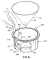
- FIG. 6 is an exploded perspective view of the filter liner having an adhesive strip and filter
- FIG. 7 is a perspective view of a used filter and filter liner connected together and removed from the low velocity chamber of the vacuum cleaner;
- FIG. 8 is a partial top view of a filter arrangement positioned in a modified filter liner having a dust door
- FIG. 9 is a perspective view of a used filter and modified filter liner connected together and removed from the low velocity chamber of the vacuum cleaner, which filter liner includes a sealing patch;
- FIG. 10 is an enlarged sectional top view of a modified filter liner positioned about the inlet nozzle of the vacuum cleaner.
- FIG. 11 is a cross sectional view similar to FIG. 3 illustrating the top of the filter liner not connected to the filter.
- FIG. 1 shows a canister type vacuum cleaner A having a housing 10 which is similar in design to the vacuum cleaner housing disclosed in U.S. Pat. No. Des. 432,746 and in U.S. patent application Ser. No. 09/809,841 filed Mar. 19, 2001, which are incorporated herein by reference.
- a handle 20 designed to enable a user to carry or move the vacuum cleaner to various locations, and/or to lift a portion of the housing to access one or more internal components of the vacuum cleaner such as the filters.
- Secured to the base 30 of the housing are two sets of wheels 32 , 34 .
- Wheels 32 are swivel wheels that are connected to the front of the base and enable the vacuum cleaner to be moved in a variety of directions.
- Wheels 34 are non-swivel wheels that are connected to the rear of the base. As can be appreciated, all the wheels can be the same type of wheel.
- a portion of the housing includes a clear or transparent section or panel 40 which enables a user to view the interior of the housing. Typically, the clear section 40 allows the user to view the amount of dust and/or dirt that has accumulated in the low velocity chamber 52 . The clear section may also or alternatively allow the user to view the condition of one or more filters in the low velocity chamber so that the user can determine if one or more filters need to be replaced. As can be appreciated, the clear section can be eliminated and a non-clear section can be used.
- Housing 10 includes a canister 50 , a motor housing 130 , expanding exhaust conduit 160 , and an exhaust filter housing 180 .
- Canister 50 includes a generally cylindrical low velocity chamber 52 .
- Low velocity chamber 52 includes a base 54 and side wall 56 .
- the base 54 includes filter well 58 containing a filter support 60 and a dirt flange 62 positioned about the filter well.
- Side wall 56 includes a side opening 64 .
- Canister 50 also includes a handle 66 connected to the side wall 56 .
- a slot 68 Positioned at the top of side wall 56 is a slot 68 which retains a seal ring 70 which forms a rib-like structure on the top surface of canister 50 .
- Positioned in side opening 64 is an inlet nozzle 72 .
- Inlet nozzle 72 includes a tubular extension 74 that extends outwardly from canister 50 and through an opening 12 in housing 10 . Positioned on the outer surface of tubular extension 74 are a plurality of ribs or ridges 76 which are designed to secure a vacuum hose H to tubular extension 74 . Inlet nozzle 72 also includes an elbow section 78 positioned in the interior of the low velocity chamber.
- Air flow through the vacuum cleaner is illustrated by arrows defining a path P.
- particle-entrained air flows through hose H and into tubular extension 74 of inlet nozzle 72 .
- the particle-entrained air continues to flow through inlet nozzle 72 , and the air path is altered by elbow section 78 .
- path P is in the form of a vortex or cyclone of several convolutions, so that particles carried by air into the low velocity chamber are removed by centrifugal force.
- FIG. 2 the air flow in the low velocity chamber is illustrated.
- the air passing through inlet nozzle 72 has a much higher velocity than in the low velocity chamber.
- the accumulated large particles D are illustrated in FIG. 2 .
- the reduction in movement or swirling of the larger particles increases filter efficiency and reduces the number of larger particles becoming re-entrained in the air.
- the accumulation behind the elbow section increases. Dirt flange 62 , as shown in FIG. 1 , and side wall 56 maintain the accumulated particles in a specific region of the base of the low velocity chamber.
- a filter liner 200 is inserted in the base of the low velocity chamber.
- the use of the liner simplifies the disposal of dirt in the canister and reduces the amount of time and effort needed to clean the interior of the low velocity chamber after each filter replacement.
- the filter liner is formed of a substantially air impermeable material such as a plastic material; however, other materials can be used.
- the filter liner is also made of a noncollapsible material that resists deformation during the operation of the vacuum cleaner. Typically, the liner is made from a blow-molded plastic. As illustrated in FIGS.
- the filter liner is shaped so as to closely conform to the majority of the inner surfaces of the side walls of the low velocity chamber and to generally conform to the base of the low velocity chamber. As can be appreciated, the filter liner can be formed to more closely conform to the shape of the base of the low velocity chamber, and/or conform less closely to the side of the low velocity chamber.
- filter liner 200 includes a side wall 202 and a base 204 .
- Base 204 includes a generally conical portion 206 in the center of the base that is designed to fit in a filter support 60 of the low velocity chamber.
- the filter liner also includes a side opening 210 and an elbow 212 which are designed to receive elbow section 78 of inlet nozzle 72 .
- Elbow 212 of the filter liner functions as a barrier to at least partially inhibit or prevent the particles from continuing to circulate about the base of the low velocity chamber.
- Elbow 212 is illustrated as having an upper curved portion that closely conforms to the top curved surface of elbow section 78 of the inlet nozzle.
- the lower portion of elbow 212 extends vertically downward to intersect with base 204 of the filter liner.
- elbow 212 can be designed to closely conform to the full shape of elbow section 78 of the inlet nozzle.
- the outside side of the filter liner includes an opening cavity 209 for opening 210 .
- the shape of the opening cavity is designed to facilitate in the insertion and removal of the filter liner from the low velocity chamber.
- an upper lip 222 Connected to the top edge 220 of the filter liner is an upper lip 222 .
- the upper lip extends outwardly from the side wall of the filter liner.
- a sealing notch 230 Positioned on the bottom surface of the upper lip is a sealing notch 230 which is designed to form a substantially air tight seal with the upper edge of the low velocity chamber.
- Two tabs 240 are diametrically positioned on the upper lip of the filter liner. The tabs are used to remove and/or position the filter liner in the low velocity chamber.
- the tabs can also include information about the filter liner and/or the vacuum cleaner.
- the elbow of the filter liner includes a seal flange 213 .
- the seal flange is designed to be inserted to a slot 79 on the inlet nozzle 78 .
- the seal flange facilitates in maintaining the filter liner in position in the low velocity chamber.
- the seal flange also or alternatively forms a seal between the filter liner and the inner surface of the low velocity chamber in a region about the inlet nozzle. After the air flows through the inlet nozzle, the air flows into the filter liner. At a location near the inside wall of the low velocity chamber and where the inlet nozzle ends and the filter liner begins, the inflowing air has a tendency to flow behind the filter liner.
- the seal flange is designed to inhibit or prevent such air flow patterns.
- the seal flange extends rearwardly of the opening of the inlet nozzle and into slot 79 .
- the seal flange is illustrated as a thin strip of material extending from the side of the filter liner.
- the seal flange can be integrally formed with the filter liner, or be later connected to the filter liner.
- the seal flange can be the same or a different material than the filter liner.
- the seal flange is a paper strip, plastic strip, cardboard strip, and/or the like, that is connected to the side of the filter liner by an adhesive, heat bonding, VELCRO, and/or the like.
- other designs of the seal flange can be used such as, but not limited to, a bead of plastic or rubber, or the like.
- the air flow path P in the low velocity chamber maintains a generally cyclonic pathway until the air contacts filter 80 . Thereafter, air flow path P is generally in an upwardly vertical direction so that the air being cleaned moves through a generally conically-shaped filter 80 .
- the generally conical filter is designed to remove very small particles from the air.
- filter 80 is designed to remove the majority of particles entrained in the air as the air passes through the filter.
- filter 80 is a High Efficiency Particulate Air (HEPA) filter.
- the filter can include one or more filter sections to remove particles mechanically and/or electrostatically from the air. When filter 80 is made of multiple layers, the multiple layers can be connected together by any conventional means.
- the fibers used in the filter may be all cellulosic fibers, all synthetic textile fibers or a mixture of cellulosic fibers and synthetic textile fibers.
- a wide variety of synthetic fibers may be used including acrylic fibers, polyester fibers, nylon fibers, olefin fibers, and/or vinyl fibers, and the like.
- the cellulosic fiber may be cellulose fibers, modified cellulose fibers, methylcellulose fibers, rayon, and/or cotton fibers.
- the filter layers are connected together by a binder, melted seam, adhesive, stitching, and/or are needle pointed together.
- the materials used to form each layer may be the same or different.
- the layers may be all woven or non-woven or a combination thereof.
- the exterior surface 82 of filter 80 is made up of a relatively durable material so as to resist damage to the filter during operation of the vacuum cleaner and/or during insertion or removal of the filter from the vacuum cleaner.
- Filter 80 is typically formed of materials which resist growth to mold, mildew, fungus, or bacteria. The materials also typically resist degradation over time, and are able to withstand extremes in temperatures and humidity, i.e. up to 70° C. (158° F.) and 100% relative humidity.
- filter 80 can be designed to be, if desired, used in both wet and dry environments.
- filter 80 removes substantially all particles having a size greater than 2 microns.
- Filter 80 typically has about a 99% air filtration efficiency for particles greater than 2 microns in size.
- filter 80 filters out over about 99.9% of the particles 2 microns or greater in size, and typically over about 99% of the particles about 0.3 micron or greater in size.
- filter 80 generally has a filtration efficiency of at least about 70% and more preferably at least about 99.9%. Particle removal efficiencies as high as 99.98% for particles 0.1 micron and greater in size and at air flow rates of 10–60 CFM are achievable by filter 80 .
- the weight of the materials of filter 80 generally is about 30–300 gm/m 2 , and typically about 50–250 gm/m 2 , which results in a very nominal pressure drop as the air passes through filter 80 .
- Filter 80 can also include a gas absorbing and/or adsorbing substance.
- the gas absorbing and/or adsorbing substance can be incorporated into the particle filter layer or layers and/or can be formed from a separate filter layer and/or altogether separate filter.
- the gas absorbing and/or adsorbing substance is designed to remove undesirable gases from the air, such as smoke or other undesirable odors.
- the gas absorbing and/or adsorbing substance can include a variety of powders such as, but not limited to, activated carbon, activated charcoal, diatomaceous earth, Fuller's earth, volcanic rock, lava rock, baking soda, and/or the like.
- the gas absorbing and/or adsorbing substance typically removes odors caused by, but not limited to, aromatic solvents, polynuclear aromatics, halogenated aromatics, phenolics, aliphatic amines, aromatic amines, ketones, esters, ethers, alcohols, fuels, halogenated solvents, aliphatic acids, and/or aromatic acids.
- aromatic solvents polynuclear aromatics, halogenated aromatics, phenolics, aliphatic amines, aromatic amines, ketones, esters, ethers, alcohols, fuels, halogenated solvents, aliphatic acids, and/or aromatic acids.
- MEDIpure One particular gas and particle filter which can be used is sold under the trademark MEDIpure.
- the MEDIpure filter is more fully described in U.S. Pat. No. 6,090,184, which is incorporated by reference.
- filter support 90 is conically-shaped and formed by a plurality of fin sections 92 that are generally positioned symmetrically from one another. Each fin section has an outer edge 94 and inner edge 96 .
- the lower portion of the filter support includes an opening 98 positioned between two adjacently positioned fin sections.
- the fin sections are maintained in position with respect to one another by being connected together at the base 100 of the filter support.
- a rigidity ring Positioned approximately mid-height of the filter support is a rigidity ring that connects the fin sections together.
- the filter support also includes a top rim.
- the rigidity panels Positioned between the top rim and rigidity ring are rigidity panels positioned between two adjacent fin sections.
- the rigidity panels can include openings but are typically solid.
- the inner edge of the fin sections form an inner cavity 108 .
- the inner cavity is conically-shaped; however, other shapes can be formed.
- the inner cavity includes a top ledge positioned below the rigidity ring.
- the filter liner 200 and filter 80 are shown to be sealed between the canister 50 and motor housing support 148 by seal rings 70 and 154 on the canister and the motor housing, respectively.
- Motor housing support 148 includes a groove 153 , wherein seal ring 154 is inserted therein.
- Side wall 56 of the canister also includes a groove 71 , wherein seal ring 70 is inserted therein.
- the liner simplifies the disposal of dirt in the canister and reduces the amount of time and effort needed to clean the interior of the low velocity chamber after each filter replacement.
- the filter and filter liner are simultaneously disposed of after one or more uses of the vacuum cleaner. Thereafter, a new liner is inserted in the low velocity chamber prior to inserting the filter and filter support 90 .
- the canister is repositioned on base 30 of housing 10 .
- the filter liner, filter and/or filter support can be positioned in the low velocity chamber after the canister has been repositioned in the base.
- the liner, filter and/or filter support can be removed from the low velocity chamber without having to first remove the canister from base 30 .
- the upper edge of filter 80 is positioned over seal ring 70 on canister 50 .
- the upper section 22 of housing 10 is pivoted back to the closed position. As shown in FIG. 1 , back support 24 retains canister 50 in the proper position when the housing is closed. This procedure is repeated for further filter removals.
- filter liner 200 and filter 80 are connected together by an adhesive 250 .
- the filter liner and filter can be preconnected by the manufacturer, distributor or retailer of the filter liner and filter prior to being offering to the consumer. Alternatively, the filter liner and filter can be offered separately and connected together prior to insertion into the low velocity chamber. Such an arrangement can be accomplished by the modified filter liner disclosed in FIG. 6 .
- Filter liner 200 includes an adhesive bead 250 on upper lip 222 .
- the adhesive bead is covered by a tape strip 252 .
- the tape strip is typically designed so as to easily be removed from the adhesive bead.
- the tape strip includes a low stick finish such as, but not limited to, a waxy surface finish.
- the filter and filter liner are connected together by removing the tape strip and inserting the filter in the filter liner.
- the filter and filter liner can be sold separately and/or sold without having to be first connected together.
- seal rings 70 and 154 on canister 50 and motor housing support 148 will cause the filter and filter liner to be pressed together, thereby resulting in an adhesive bond between the filter and filter liner.
- the adhesive can be selected such that the bond between the filter and filter liner cannot be easily broken once formed.
- the adhesive can be selected such that the bond between the filter and filter liner can be easily broken once formed.
- the adhesive is selected such that the bond between the filter and filter liner cannot be easily broken once formed.
- One potential advantage of not having a filter preconnected to the filter liner is that the operator may more easily insert the filter liner into the low velocity chamber.
- the filter liner can be designed such that the top of the filter liner does not contact and/or is not connected to filter 80 .
- the top edge of the filter liner is positioned below filter 80 .
- the top of the filter liner engages a flange 73 of seal ring 70 .
- the flange forms a seal or barrier with the upper edge of the filter liner to inhibit or prevent particles from falling behind the filter liner and into the low velocity chamber.
- the seal or barrier also or alternatively facilities in the proper air flow from within the filter liner so as to maintain the desired filter efficiencies.
- a safety filter is typically positioned in inner cavity 108 .
- the safety filter is designed to at least partially inhibit or prevent large particles or other articles from entering the motor housing and causing damage to the components in the motor housing. Large particles can enter the motor housing when filter 80 becomes torn or otherwise damaged, is improperly positioned in the vacuum cleaner, and/or if the user forgets to place filter 80 in the vacuum cleaner prior to use.
- the safety filter is used to capture or entrap large particles that pass through the openings of the filter support.
- the safety filter is conical in shape to fit in inner cavity 108 .
- a conically-shaped safety filter support is typically used to maintain the safety filter in the inner cavity.
- the safety filter support generally includes a plurality of openings and a rim. The rim is designed to be positioned on top of ledge of the filter support.
- the small particles in the air are then directed to filter 80 wherein a majority of the particles are filtered out of the air by the filter.
- the filtered air passing through the filter passes through openings 98 in the filter support.
- the filtered air then passes through a safety filter that is positioned in inner cavity 108 of the filter support.
- the filtered air then passes through the safety filter and into the motor housing in a direction defined by air path P, as shown in FIG. 1 .
- Air is drawn through filter 80 by a fan 132 driven by a motor 134 , both of which are positioned in the motor housing 130 .
- the motor housing includes a lower inlet 136 and an air exhaust opening 138 .
- the motor is typically an electric motor powered by 120 or 240V and causes fan 132 to rotate at about 10000–30000 RPM.
- the turning fan causes the air to flow through the low velocity chamber at about 20–100 CFM.
- the static suction produced by the rotating fan is about 40–150 inches plus the water lift.
- the motor rests on a vibration ring 140 to minimize noise and vibration during operation of the vacuum cleaner.
- the motor housing includes an upper section 142 and a lower section 144 .
- a housing support 148 supports the motor housing on the top of the low velocity chamber.
- the end of the housing support forms a rim 150 that includes a seal slot 152 and a seal ring 154 positioned therein.
- the end of filter 80 and filter liner 200 are secured between seal ring 154 on housing support 148 and seal ring 70 on the top of side wall 56 .
- the seal formed between seal rings 70 and 154 at least partially inhibits or prevents air from bypassing filter 80 and filter liner 200 , and from entering the motor housing when the motor housing is positioned on the top of canister 50 .
- the conduit expands in size along the longitudinal length of the conduit.
- the height of the inner passageway of the conduit increases along the longitudinal length of the conduit.
- the increase in height is caused by upper wall 168 remaining substantially planar and bottom wall 170 having an arcuate shape that curves downwardly.
- many other arrangements can be used to cause the height of the passageway to increase such as, but not limited to, the upper wall curving upwardly and the bottom wall remaining substantially planar, both the upper and lower walls curving away from one another, one or both walls being planar and angling away from one another, etc.
- the width of the inner passageway also increases along the longitudinal length of the conduit.
- the side walls 172 curve away from one another to cause the width of the conduit to increase.
- the width of the conduit can be increased by use of other conduit configurations such as, but not limited to, side walls 172 curving outwardly. It has been found that by causing the size of the passageway to increase along the longitudinal length of the conduit, the throughput of air is increased. This is believed to be caused by venturi expansion effects. The combined use of the motor housing and expanding conduit have resulted in at least 5% and typically 10–40% greater efficiencies in air throughput.
- the filtered air upon exiting the conduit through the conduit second end 176 , enters exhaust filter housing 180 .
- the filter housing 180 includes a front and rear wall section 182 , 184 .
- the two sections are connected together by a plurality of screws; however, the two wall sections can be connected together by other means.
- the rear wall includes a slot used to connect the rear wall to the second end 176 of conduit 160 .
- Support flanges 190 , 192 are secured between the front and rear wall sections. The support flanges stabilize and secure the filter housing in vacuum cleaner housing 10 .
- Positioned in the filter chamber 194 and formed between the front and rear walls is a gas filter 200 .
- the gas filter is designed to remove any noxious or undesired gases in the filtered exhausted air.
- the gas filter can take on a number of different forms so long as the exhausted air at least partially contacts one or more gas absorbing and/or adsorbing agents.
- Non-limiting forms of the gas filter include a granular and/or powered gas absorbing and/or adsorbing agent that is lacily piled up or formed in a rigid or semi-rigid shape, a granular and/or powered gas absorbing and/or adsorbing agent impregnated in a paper, matte and/or fabric material, etc.
- the gas filter can also be designed to filter out particles that still remain in the exhausted air.
- a gas filter is typically positioned in the filter housing, the gas filter can be substituted for a particle filter, if desired.
- a scent agent can be positioned in the filter housing as an alterative to or in addition to one or more filters in the filter housing.
- the scent agent can be in the form of scented paper, a scented pad, a scented bar, scented granules, etc.
- the scent agent is used to mask odors exiting the vacuum cleaner and/or to provide a fresh or desired scent to the environment while the user is cleaning.
- a opening flange 198 is positioned about the opening and includes one or more ridges 199 that are designed to secure hose H to the opening when the user desires to use the vacuum cleaner as a blower. As shown in FIG. 1 , opening 196 extends through an exit opening 14 in housing 10 .
- housing 10 includes an upper section 22 and a base 30 .
- Upper section 22 is designed to pivot about opening 12 so that the user can access and remove canister 50 from the interior of housing 10 .
- Back support 24 on upper section 22 rests on base 30 when the housing sections are closed. When the user needs to open the housing, back support 24 is lifted off base 30 and continues to pivot the upper section about a pivot point near opening 12 , not shown, until canister 50 is exposed.
- the lifting of upper section 22 causes the motor housing to be lifted off filter support 90 and off of filter 80 and filter liner 200 .
- the upper section can be designed such that the upper section is completely lifted off the base of the housing instead of being pivoted to an opened position.
- the user grasps handle 66 on the canister and slides the canister off base 30 .
- the canister is then moved to a location to remove dirt D from the base of the filter liner and to replace filter 80 and filter liner 200 .
- filter 80 and filter liner 200 are lifted out of the canister and disposed of.
- the adhesive between the filter and the filter liner is typically designed to prevent the separation of the filter from the filter liner so as to minimize the amount of particles that escape during the disposal of the filter and the filter liner.
- the use of the filter liner also eliminates the need to carry the canister to a disposal site. As a result, the changing of the filter is made simpler and more convenient by the use of the filter liner.
- the filter liner includes a dust door 260 connected to one side of the filter liner.
- the dust door is designed to at least partially close opening 210 during the removal of the filter liner from the canister.
- opening 210 can allow particles to spill through the opening during the changing of the filter liner and the filter.
- the dust door is designed to at least partially close the opening to thereby limit the amount of particles that spill from the opening.
- the dust door is biased in the closed position.
- the dust door is drawn open by the vacuum inside the low velocity chamber. Once the vacuum cleaner is turned off, the dust door moves back to the closed position.
- the opening in the filter liner is partially or completely closed, thereby limiting the amount of particles that escape through the opening during the disposal of the filter and the filter liner.
- the outside surface of the filter liner includes a sealing patch 270 that is removably connected a patch surface 272 .
- sealing patch 270 is designed to be applied over the opening in the side of the filter liner. By covering the opening, particles are inhibited or prevented from spilling out of the opening during the disposal of the filter liner and the filter.
- the sealing patch can include instructions on the face of the patch to provide information on when and/or how to use the sealing patch, and/or may contain other information a about the vacuum cleaner.
- the patch surface is positioned at a location away from the opening.
- the sealing patch typically includes an adhesive surface that adheres to a region about the opening in the filter liner. In this design, the patch surface typically includes a low-stick or nonstick surface that allows the seal patch to be removed from the patch surface and then inserted over the opening.
- the sealing patch can be used in conjunction with the dust door as discussed above.
- a new filter and filter liner can be inserted into the canister. If the filter and filter liner are preconnected, the filter and filter liner are simultaneously inserted into the canister. If the filter liner and filter are separate, the filter liner is first placed in the canister and then the filter. If the filter liner includes a tape strip on the upper lip, the tape strip is removed prior to inserting the filter in the filter liner.
- a conical filter 80 is used to remove particles entrained in the air.
- Filter support 90 causes the filter to substantially retain its conical shape.
- the shape of filter 80 does become somewhat deformed when the vacuum cleaner is turned on.
- motor 134 begins rotating fan blade 132 resulting in a vacuum being formed in low velocity chamber 52
- filter 80 is drawn toward filter support 90 .
- filter 80 is retained in position by the fin sections of the filter support, and is drawn inwardly between the regions of the fin sections, thereby creating a plurality of ribs 86 and trough portions 88 on the filter.
- the rib and trough portions of the deformed filter enhance the life and effectiveness of the filter.
- the air path about the filter is substantially tangential to the end of ribs 86 .
- the ribs function as a barrier or accumulation point for the particles in the air, especially the large particles.
- Large particles D accumulate on the ribs of the filter and/or are stopped by the rib and fall to the base of the low velocity chamber. Since the ribs on the filter occupy a small area relative to the complete outer surface area of the filter, few particles can accumulate on the ribs.
- the large particles are knocked off or fall off the ribs and onto the base of the low velocity chamber, as shown in FIGS. 7 and 9 .
- the air velocity and air paths are different in the rib and trough portions, larger particles are less likely to adhere to the trough section of the filter as opposed to the ribs. Since most of the large to medium particles fall into the low velocity chamber, or accumulate on the limited regions of the ribs, the majority of the filter is able to filter out the smaller particles in the air as the air passes through the trough portions of the filter. Prior filter profiles equally exposed the complete outer filter surface to large and small particles in the air. As a result, the filter life was significantly reduced. It has been found that the self cleaning effects of the filter due to rib and trough section filter profile increase the filter life by at least 5%, and typically 10–25%.
Abstract
Description
Claims (85)
Priority Applications (1)
| Application Number | Priority Date | Filing Date | Title |
|---|---|---|---|
| US10/113,579 US7018438B2 (en) | 2002-03-29 | 2002-03-29 | Filtering system |
Applications Claiming Priority (1)
| Application Number | Priority Date | Filing Date | Title |
|---|---|---|---|
| US10/113,579 US7018438B2 (en) | 2002-03-29 | 2002-03-29 | Filtering system |
Publications (2)
| Publication Number | Publication Date |
|---|---|
| US20030182756A1 US20030182756A1 (en) | 2003-10-02 |
| US7018438B2 true US7018438B2 (en) | 2006-03-28 |
Family
ID=28453635
Family Applications (1)
| Application Number | Title | Priority Date | Filing Date |
|---|---|---|---|
| US10/113,579 Expired - Fee Related US7018438B2 (en) | 2002-03-29 | 2002-03-29 | Filtering system |
Country Status (1)
| Country | Link |
|---|---|
| US (1) | US7018438B2 (en) |
Cited By (11)
| Publication number | Priority date | Publication date | Assignee | Title |
|---|---|---|---|---|
| US20060090290A1 (en) * | 2004-11-01 | 2006-05-04 | Lau Ying W | Handheld vacuum with accelerated cyclonic flow and air freshener |
| US20060213025A1 (en) * | 2005-03-25 | 2006-09-28 | Sawalski Michael M | Soft-surface remediation device and method of using same |
| US20060288516A1 (en) * | 2005-06-23 | 2006-12-28 | Sawalski Michael M | Handheld mechanical soft-surface remediation (SSR) device and method of using same |
| US20060288495A1 (en) * | 2005-06-28 | 2006-12-28 | Sawalski Michael M | System for and method of soft surface remediation |
| US20070190319A1 (en) * | 2006-02-13 | 2007-08-16 | Donaldson Company, Inc. | Polymer blend, polymer solution composition and fibers spun from the polymer blend and filtration applications thereof |
| US20090044372A1 (en) * | 2007-07-09 | 2009-02-19 | Knopow Jeremy F | Handheld Portable Devices for Touchless Particulate Matter Removal |
| US20120047682A1 (en) * | 2010-09-01 | 2012-03-01 | Makarov Sergey V | Vacuum cleaner with exhaust tube having an increasing cross-sectional area |
| US20130152524A1 (en) * | 2010-06-16 | 2013-06-20 | Mahle International Gmbh | Filter arrangment, in particular air filter arrangement |
| US8661609B2 (en) | 2008-12-03 | 2014-03-04 | S.C. Johnson & Son, Inc. | Portable devices for touchless particulate matter removal |
| US20140093301A1 (en) * | 2011-06-15 | 2014-04-03 | Hyoung-Kwon Cho | Device for connecting vacuum cleaner bag |
| US11116369B2 (en) | 2016-04-27 | 2021-09-14 | Diversey, Inc. | Vacuum cleaner |
Families Citing this family (21)
| Publication number | Priority date | Publication date | Assignee | Title |
|---|---|---|---|---|
| US7331083B2 (en) * | 2002-12-18 | 2008-02-19 | Panasonic Corporation Of North America | Lighted wand assembly with remote light source |
| WO2004056251A2 (en) * | 2002-12-18 | 2004-07-08 | Matsushita Electric Corporation Of America | Lighted wand assembly |
| EP1525839A3 (en) * | 2003-10-23 | 2006-01-25 | Polar Light Limited | Dirt container for a surface cleaning apparatus and method of use |
| FR2862859B1 (en) * | 2003-11-27 | 2006-03-03 | Seb Sa | DEVICE FOR SEPARATING WASTE FOR VACUUM CLEANERS |
| US20050229777A1 (en) * | 2004-04-16 | 2005-10-20 | Brown Jeffrey A | Method and apparatus for filtering particulate matter from an air-flow |
| US7749293B2 (en) * | 2006-03-10 | 2010-07-06 | G.B.D. Corp. | Vacuum cleaner with a removable cyclone array |
| US20090193973A1 (en) * | 2008-02-05 | 2009-08-06 | Americair Corporation | Vacuum and ambient air hepa filtration system |
| KR101471026B1 (en) * | 2008-03-05 | 2014-12-11 | 삼성전자주식회사 | Vacuum cleaner in which dust bag or cyclone dust collecting apparatus is selectively mounted |
| US20100139031A1 (en) * | 2008-12-10 | 2010-06-10 | Kevin Willmorth | Containment Device |
| US10258210B2 (en) | 2016-12-27 | 2019-04-16 | Omachron Intellectual Property Inc. | Multistage cyclone and surface cleaning apparatus having same |
| US11285495B2 (en) | 2016-12-27 | 2022-03-29 | Omachron Intellectual Property Inc. | Multistage cyclone and surface cleaning apparatus having same |
| US10299643B2 (en) | 2016-12-27 | 2019-05-28 | Omachron Intellectual Property Inc. | Multistage cyclone and surface cleaning apparatus having same |
| US10016106B1 (en) | 2016-12-27 | 2018-07-10 | Omachron Intellectual Property Inc. | Multistage cyclone and surface cleaning apparatus having same |
| US10405709B2 (en) | 2016-12-27 | 2019-09-10 | Omachron Intellectual Property Inc. | Multistage cyclone and surface cleaning apparatus having same |
| US10827891B2 (en) | 2016-12-27 | 2020-11-10 | Omachron Intellectual Property Inc. | Multistage cyclone and surface cleaning apparatus having same |
| US10271704B2 (en) | 2016-12-27 | 2019-04-30 | Omachron Intellectual Property Inc. | Multistage cyclone and surface cleaning apparatus having same |
| WO2018207327A1 (en) * | 2017-05-11 | 2018-11-15 | 三菱電機株式会社 | Cyclone separation apparatus and vacuum cleaner |
| EP3692883A1 (en) * | 2019-02-05 | 2020-08-12 | Hilti Aktiengesellschaft | Dust suction device and method for replacing a filter element in a dust suction device |
| US11246462B2 (en) | 2019-11-18 | 2022-02-15 | Omachron Intellectual Property Inc. | Multi-inlet cyclone |
| US11751740B2 (en) | 2019-11-18 | 2023-09-12 | Omachron Intellectual Property Inc. | Multi-inlet cyclone |
| US20240041284A1 (en) * | 2022-08-03 | 2024-02-08 | Omachron Intellectual Property Inc. | Docking unit for a surface cleaning apparatus |
Citations (92)
| Publication number | Priority date | Publication date | Assignee | Title |
|---|---|---|---|---|
| US1921085A (en) | 1929-10-18 | 1933-08-08 | Siemens Ag | Electrical vacuum cleaner |
| US2003833A (en) | 1931-10-19 | 1935-06-04 | Gen Res Corp | Free wheeling clutch |
| US2139736A (en) | 1936-11-19 | 1938-12-13 | Kenneth P Durham | Vortical muffling device |
| US2242278A (en) | 1940-04-19 | 1941-05-20 | Jr Edward H Yonkers | Suction cleaner |
| US2394923A (en) | 1943-11-03 | 1946-02-12 | William P Little | Dust collector |
| US2608268A (en) | 1948-06-17 | 1952-08-26 | Hoover Co | Suction cleaner |
| US2627937A (en) | 1950-08-24 | 1953-02-10 | Royal Vacuum Cleaner Company | Suction cleaner motor filter construction |
| US2627936A (en) | 1950-08-24 | 1953-02-10 | Royal Vacuum Cleaner Company | Suction cleaner dome mounting construction |
| US2763886A (en) | 1950-09-26 | 1956-09-25 | Jr Charles Kepler Brown | Vacuum mop and strainer |
| US3343344A (en) | 1965-12-14 | 1967-09-26 | Health Mor Inc | Suction cleaner and filter construction |
| US3545181A (en) | 1968-05-07 | 1970-12-08 | Bernard W Young | Air cleaning apparatus |
| US3724181A (en) | 1971-06-11 | 1973-04-03 | Envirco Corp | Process for separating particles from aerosols |
| US3804942A (en) | 1971-11-16 | 1974-04-16 | Shimizu Construction Co Ltd | Air purifier |
| US3853512A (en) | 1972-11-29 | 1974-12-10 | Nissan Motor | Air purifier |
| US3870495A (en) | 1972-12-22 | 1975-03-11 | Air Purification Systems Inc | Particulate and/or gas filters and associated filtering equipment to purify air to be breathed by persons in vehicles and/or buildings, and manufacture and installation of these filters |
| US3925043A (en) | 1973-11-13 | 1975-12-09 | Environment One Corp | Low cost, efficient, general purpose air cleaner cartridge |
| US3953184A (en) | 1974-09-18 | 1976-04-27 | Stockford William F | Cyclone-type dust separator |
| US3966597A (en) | 1970-07-28 | 1976-06-29 | Teijin Limited | Oil or organic solvent-absorbent |
| US3998916A (en) | 1974-03-25 | 1976-12-21 | N.V. Verto | Method for the manufacture of an electret fibrous filter |
| DE2711111A1 (en) | 1976-03-16 | 1977-09-29 | Nederman Bill P Ph | FILTER UNIT FOR SEPARATING SOLID PARTICLES FROM GASES |
| US4121916A (en) | 1976-10-26 | 1978-10-24 | Fricke Roy A | Portable air purge |
| US4229193A (en) | 1978-09-19 | 1980-10-21 | Shop-Vac Corporation | Vacuum cleaner and sealed filter bag assembly therefor particularly useful for filtering asbestos fibers from air |
| US4276070A (en) * | 1978-12-23 | 1981-06-30 | Rommag P. Worwag & Co. | Removable dust collecting container for professional and household vacuum cleaners |
| US4339250A (en) | 1980-07-17 | 1982-07-13 | Thut Timothy T | Fresh air fountain air filter arrangement |
| US4365980A (en) | 1981-08-20 | 1982-12-28 | Farr Company | Air filter assembly |
| US4377399A (en) | 1981-02-06 | 1983-03-22 | Vaportek, Inc. | Air freshening device |
| US4378234A (en) | 1978-12-07 | 1983-03-29 | Kawasaki Jukogyo Kabushiki Kaisha | Particulate material collecting apparatus |
| US4385911A (en) | 1982-01-22 | 1983-05-31 | Ronco Teleproducts, Inc. | Air filtering device |
| US4477270A (en) | 1983-01-07 | 1984-10-16 | Franz Tauch | Air filter |
| US4504290A (en) | 1984-06-14 | 1985-03-12 | Columbus Industries, Inc. | Odor filter media |
| US4507819A (en) | 1984-02-16 | 1985-04-02 | Health-Mor, Inc. | Power nozzle sudser for canister type vacuum cleaner |
| US4514197A (en) | 1983-02-15 | 1985-04-30 | Armbruster Joseph M | Filter for air circulator |
| US4531956A (en) | 1981-11-10 | 1985-07-30 | Howorth Air Engineering Limited | Sterile air trolley |
| US4627862A (en) | 1984-02-07 | 1986-12-09 | Plaston Ag | Air cleaning apparatus |
| US4629482A (en) | 1985-08-05 | 1986-12-16 | Enviracaire Corporation | HEPA room air purifier |
| US4650505A (en) | 1983-10-17 | 1987-03-17 | A/S Fisker & Nielsen | Cleaner apparatus for toxic or hazardous substances |
| US4687697A (en) | 1985-09-11 | 1987-08-18 | Lydall, Inc. | Composite having improved transverse structural integrity and flexibility for use in high temperature environments |
| US4687579A (en) | 1986-05-02 | 1987-08-18 | The United States Of America As Represented By The United States Department Of Energy | Sintered composite medium and filter |
| US4702753A (en) | 1986-04-21 | 1987-10-27 | Thaddeus Kowalczyk | Air purifier-combination filter |
| US4737173A (en) | 1986-07-03 | 1988-04-12 | Amway Corporation | Room air treatment system |
| US4749390A (en) | 1987-02-26 | 1988-06-07 | Air Purification Products, International | Four-sided air filter |
| US4750924A (en) | 1987-07-06 | 1988-06-14 | Frank Potter | Clean air flow and temperature equalizing apparatus |
| US4784676A (en) | 1987-11-12 | 1988-11-15 | Hale Dorothy G | Disposable vacuum cleaner bag |
| US4810269A (en) | 1988-04-27 | 1989-03-07 | Stackhouse Associates, Inc. | Point one micron filtering system |
| US4874659A (en) | 1984-10-24 | 1989-10-17 | Toray Industries | Electret fiber sheet and method of producing same |
| US4886527A (en) | 1987-09-19 | 1989-12-12 | Firma Carl Freudenberg | Multilayer electret filter and process of using same |
| US4900344A (en) | 1987-11-10 | 1990-02-13 | Jvj Enterprises, Inc. | Portable room air filter |
| US4902306A (en) | 1988-08-09 | 1990-02-20 | Air Purification Products International, Inc. | Dual-dipole electrostatic air filter |
| US4909815A (en) | 1988-10-24 | 1990-03-20 | International Air Filter, Inc. | Mobile air cleaning apparatus |
| US4917942A (en) | 1988-12-22 | 1990-04-17 | Minnesota Mining And Manufacturing Company | Nonwoven filter material |
| US4921510A (en) | 1984-10-03 | 1990-05-01 | Arnold Plooy | Vacuum cleaner system |
| US4927437A (en) | 1989-02-21 | 1990-05-22 | Richerson Ben M | Cyclonic separator for removing and recovering airborne particles |
| JPH02187114A (en) | 1989-01-13 | 1990-07-23 | Sanyo Electric Co Ltd | Air purifier |
| FR2653354A1 (en) | 1989-10-25 | 1991-04-26 | Poelman Sofiltra | Self-contained and portable filtration equipment |
| US5037455A (en) | 1990-09-14 | 1991-08-06 | The Great American Filter Company | Air filter |
| US5090976A (en) * | 1990-09-21 | 1992-02-25 | Notetry Limited | Dual cyclonic vacuum cleaner with disposable liner |
| US5108470A (en) | 1988-11-01 | 1992-04-28 | William Pick | Charging element having odor and gas absorbing properties for an electrostatic air filter |
| JPH04197460A (en) | 1990-11-28 | 1992-07-17 | Matsushita Electric Ind Co Ltd | Air cleaner |
| US5141706A (en) | 1989-06-30 | 1992-08-25 | Clark Donald L | Air purification unit |
| US5188646A (en) | 1992-03-05 | 1993-02-23 | Air Kontrol, Inc. | Adjustable air filter |
| US5221573A (en) | 1991-12-30 | 1993-06-22 | Kem-Wove, Inc. | Adsorbent textile product |
| US5240478A (en) | 1992-06-26 | 1993-08-31 | Messina Gary D | Self-contained, portable room air treatment apparatus and method therefore |
| US5248323A (en) | 1992-11-09 | 1993-09-28 | Health-Mor, Inc. | Vacuum cleaner and filter thereof |
| US5288298A (en) | 1992-06-22 | 1994-02-22 | Aston William T | Antimicrobial air filter and method of making same |
| US5287591A (en) | 1992-03-30 | 1994-02-22 | Racine Industries, Inc. | Carpet cleaning machine with convertible-use feature |
| US5290330A (en) | 1993-06-10 | 1994-03-01 | The Johns Hopkins University | HEPA filtration system |
| US5306534A (en) | 1991-03-22 | 1994-04-26 | Home Care Industries, Inc. | Vacuum cleaner bag with electrostatically charged meltblown layer |
| US5307538A (en) | 1992-03-30 | 1994-05-03 | Racine Industries, Inc. | Carpet cleaning machine for particulate removal |
| DE4240172A1 (en) | 1992-11-30 | 1994-06-01 | Miele & Cie | Vacuum cleaner with main and fine dust filters - has zigzag fine dust filter contg deodorising layer of active carbon underneath electrostatically charged granulate filter layer |
| US5350620A (en) | 1989-11-14 | 1994-09-27 | Minnesota Mining And Manufacturing | Filtration media comprising non-charged meltblown fibers and electrically charged staple fibers |
| US5358443A (en) | 1993-04-14 | 1994-10-25 | Centercore, Inc. | Dual fan hepa filtration system |
| US5399319A (en) | 1993-08-02 | 1995-03-21 | Vector Technologies Ltd. | Apparatus for filtering air and for creating a positive/negative pressure |
| US5435817A (en) | 1992-12-23 | 1995-07-25 | Honeywell Inc. | Portable room air purifier |
| US5443625A (en) | 1994-01-18 | 1995-08-22 | Schaffhausen; John M. | Air filtering fixture |
| US5478377A (en) | 1994-07-22 | 1995-12-26 | The United States Of America As Represented By The Secretary Of The Army | Filter for a respiratory device |
| US5498272A (en) | 1994-05-06 | 1996-03-12 | Leon; Marty G. | Capsule vacuum cleaner assembly |
| JPH0866341A (en) | 1994-04-19 | 1996-03-12 | Bluecher Hasso Von | Odor-absorbing filter for vacuum cleaner |
| US5515573A (en) | 1994-04-08 | 1996-05-14 | Hmi Industries Inc. | Vacuum cleaner canister base connector |
| US5593479A (en) | 1995-02-02 | 1997-01-14 | Hmi Industries, Inc. | Filter system |
| US5603741A (en) | 1994-05-09 | 1997-02-18 | Hmi Industries, Inc. | Vacuum cleaner and filter bag with air management |
| US5641343A (en) | 1996-01-25 | 1997-06-24 | Hmi Industries, Inc. | Room air cleaner |
| US5647881A (en) | 1995-04-20 | 1997-07-15 | Minnesota Mining And Manufacturing Company | Shock resistant high efficiency vacuum cleaner filter bag |
| US5837020A (en) | 1997-06-20 | 1998-11-17 | Hmi Industries, Inc. | Room air cleaner |
| US5840103A (en) | 1994-11-24 | 1998-11-24 | Notetry Limited | Vacuum cleaner and a filter assembly therefor |
| US5874052A (en) | 1992-05-15 | 1999-02-23 | Medtek Devices, Inc. | Antimicrobial filter for use in electrocautery or laser surgery |
| US5931991A (en) | 1997-03-11 | 1999-08-03 | Leon; Marty Gerard | Vacuum cleaner with sponge filter |
| JPH11309204A (en) | 1998-04-30 | 1999-11-09 | Tiger Vacuum Bottle Co Ltd | Air cleaner |
| US6003196A (en) | 1998-01-09 | 1999-12-21 | Royal Appliance Mfg. Co. | Upright vacuum cleaner with cyclonic airflow |
| US6010550A (en) | 1998-08-20 | 2000-01-04 | Song; Young-So | Air filter for a vacuum cleaner |
| US6090184A (en) | 1998-02-27 | 2000-07-18 | Hmi Industries, Inc. | Filter system |
| US6243915B1 (en) | 1999-03-15 | 2001-06-12 | Sanyo Electric Co., Ltd. | Vacuum cleaner |
| US6488744B2 (en) * | 2001-03-19 | 2002-12-03 | Hmi Industries, Inc. | Filter system |
Family Cites Families (2)
| Publication number | Priority date | Publication date | Assignee | Title |
|---|---|---|---|---|
| JPS58199204A (en) * | 1982-05-12 | 1983-11-19 | Bridgestone Corp | Pneumatic radial tyre for heavy load |
| DE3643484A1 (en) * | 1986-12-19 | 1988-06-30 | Werner Jacob | BEARING ARRANGEMENT FOR A WHEEL OF A MOTOR VEHICLE |
-
2002
- 2002-03-29 US US10/113,579 patent/US7018438B2/en not_active Expired - Fee Related
Patent Citations (96)
| Publication number | Priority date | Publication date | Assignee | Title |
|---|---|---|---|---|
| US1921085A (en) | 1929-10-18 | 1933-08-08 | Siemens Ag | Electrical vacuum cleaner |
| US2003833A (en) | 1931-10-19 | 1935-06-04 | Gen Res Corp | Free wheeling clutch |
| US2139736A (en) | 1936-11-19 | 1938-12-13 | Kenneth P Durham | Vortical muffling device |
| US2242278A (en) | 1940-04-19 | 1941-05-20 | Jr Edward H Yonkers | Suction cleaner |
| US2394923A (en) | 1943-11-03 | 1946-02-12 | William P Little | Dust collector |
| US2608268A (en) | 1948-06-17 | 1952-08-26 | Hoover Co | Suction cleaner |
| US2627937A (en) | 1950-08-24 | 1953-02-10 | Royal Vacuum Cleaner Company | Suction cleaner motor filter construction |
| US2627936A (en) | 1950-08-24 | 1953-02-10 | Royal Vacuum Cleaner Company | Suction cleaner dome mounting construction |
| US2763886A (en) | 1950-09-26 | 1956-09-25 | Jr Charles Kepler Brown | Vacuum mop and strainer |
| US3343344A (en) | 1965-12-14 | 1967-09-26 | Health Mor Inc | Suction cleaner and filter construction |
| US3545181A (en) | 1968-05-07 | 1970-12-08 | Bernard W Young | Air cleaning apparatus |
| US3966597A (en) | 1970-07-28 | 1976-06-29 | Teijin Limited | Oil or organic solvent-absorbent |
| US3724181A (en) | 1971-06-11 | 1973-04-03 | Envirco Corp | Process for separating particles from aerosols |
| US3804942A (en) | 1971-11-16 | 1974-04-16 | Shimizu Construction Co Ltd | Air purifier |
| US3853512A (en) | 1972-11-29 | 1974-12-10 | Nissan Motor | Air purifier |
| US3870495A (en) | 1972-12-22 | 1975-03-11 | Air Purification Systems Inc | Particulate and/or gas filters and associated filtering equipment to purify air to be breathed by persons in vehicles and/or buildings, and manufacture and installation of these filters |
| US3925043A (en) | 1973-11-13 | 1975-12-09 | Environment One Corp | Low cost, efficient, general purpose air cleaner cartridge |
| US3998916A (en) | 1974-03-25 | 1976-12-21 | N.V. Verto | Method for the manufacture of an electret fibrous filter |
| US3953184A (en) | 1974-09-18 | 1976-04-27 | Stockford William F | Cyclone-type dust separator |
| DE2711111A1 (en) | 1976-03-16 | 1977-09-29 | Nederman Bill P Ph | FILTER UNIT FOR SEPARATING SOLID PARTICLES FROM GASES |
| US4121916A (en) | 1976-10-26 | 1978-10-24 | Fricke Roy A | Portable air purge |
| US4229193A (en) | 1978-09-19 | 1980-10-21 | Shop-Vac Corporation | Vacuum cleaner and sealed filter bag assembly therefor particularly useful for filtering asbestos fibers from air |
| US4378234A (en) | 1978-12-07 | 1983-03-29 | Kawasaki Jukogyo Kabushiki Kaisha | Particulate material collecting apparatus |
| US4276070A (en) * | 1978-12-23 | 1981-06-30 | Rommag P. Worwag & Co. | Removable dust collecting container for professional and household vacuum cleaners |
| US4339250A (en) | 1980-07-17 | 1982-07-13 | Thut Timothy T | Fresh air fountain air filter arrangement |
| US4377399A (en) | 1981-02-06 | 1983-03-22 | Vaportek, Inc. | Air freshening device |
| US4365980A (en) | 1981-08-20 | 1982-12-28 | Farr Company | Air filter assembly |
| US4531956A (en) | 1981-11-10 | 1985-07-30 | Howorth Air Engineering Limited | Sterile air trolley |
| US4385911A (en) | 1982-01-22 | 1983-05-31 | Ronco Teleproducts, Inc. | Air filtering device |
| US4477270A (en) | 1983-01-07 | 1984-10-16 | Franz Tauch | Air filter |
| US4514197A (en) | 1983-02-15 | 1985-04-30 | Armbruster Joseph M | Filter for air circulator |
| US4650505A (en) | 1983-10-17 | 1987-03-17 | A/S Fisker & Nielsen | Cleaner apparatus for toxic or hazardous substances |
| US4627862A (en) | 1984-02-07 | 1986-12-09 | Plaston Ag | Air cleaning apparatus |
| US4507819A (en) | 1984-02-16 | 1985-04-02 | Health-Mor, Inc. | Power nozzle sudser for canister type vacuum cleaner |
| US4504290A (en) | 1984-06-14 | 1985-03-12 | Columbus Industries, Inc. | Odor filter media |
| US4921510A (en) | 1984-10-03 | 1990-05-01 | Arnold Plooy | Vacuum cleaner system |
| US4874659A (en) | 1984-10-24 | 1989-10-17 | Toray Industries | Electret fiber sheet and method of producing same |
| US4629482A (en) | 1985-08-05 | 1986-12-16 | Enviracaire Corporation | HEPA room air purifier |
| US4687697A (en) | 1985-09-11 | 1987-08-18 | Lydall, Inc. | Composite having improved transverse structural integrity and flexibility for use in high temperature environments |
| US4702753A (en) | 1986-04-21 | 1987-10-27 | Thaddeus Kowalczyk | Air purifier-combination filter |
| US4687579A (en) | 1986-05-02 | 1987-08-18 | The United States Of America As Represented By The United States Department Of Energy | Sintered composite medium and filter |
| US4737173A (en) | 1986-07-03 | 1988-04-12 | Amway Corporation | Room air treatment system |
| US4749390A (en) | 1987-02-26 | 1988-06-07 | Air Purification Products, International | Four-sided air filter |
| US4750924A (en) | 1987-07-06 | 1988-06-14 | Frank Potter | Clean air flow and temperature equalizing apparatus |
| US4886527A (en) | 1987-09-19 | 1989-12-12 | Firma Carl Freudenberg | Multilayer electret filter and process of using same |
| US4900344A (en) | 1987-11-10 | 1990-02-13 | Jvj Enterprises, Inc. | Portable room air filter |
| US4784676A (en) | 1987-11-12 | 1988-11-15 | Hale Dorothy G | Disposable vacuum cleaner bag |
| US4810269A (en) | 1988-04-27 | 1989-03-07 | Stackhouse Associates, Inc. | Point one micron filtering system |
| US4902306A (en) | 1988-08-09 | 1990-02-20 | Air Purification Products International, Inc. | Dual-dipole electrostatic air filter |
| US4909815A (en) | 1988-10-24 | 1990-03-20 | International Air Filter, Inc. | Mobile air cleaning apparatus |
| US5108470A (en) | 1988-11-01 | 1992-04-28 | William Pick | Charging element having odor and gas absorbing properties for an electrostatic air filter |
| US4917942A (en) | 1988-12-22 | 1990-04-17 | Minnesota Mining And Manufacturing Company | Nonwoven filter material |
| JPH02187114A (en) | 1989-01-13 | 1990-07-23 | Sanyo Electric Co Ltd | Air purifier |
| US4927437A (en) | 1989-02-21 | 1990-05-22 | Richerson Ben M | Cyclonic separator for removing and recovering airborne particles |
| US5141706A (en) | 1989-06-30 | 1992-08-25 | Clark Donald L | Air purification unit |
| FR2653354A1 (en) | 1989-10-25 | 1991-04-26 | Poelman Sofiltra | Self-contained and portable filtration equipment |
| US5350620A (en) | 1989-11-14 | 1994-09-27 | Minnesota Mining And Manufacturing | Filtration media comprising non-charged meltblown fibers and electrically charged staple fibers |
| US5037455A (en) | 1990-09-14 | 1991-08-06 | The Great American Filter Company | Air filter |
| US5090976A (en) * | 1990-09-21 | 1992-02-25 | Notetry Limited | Dual cyclonic vacuum cleaner with disposable liner |
| JPH04197460A (en) | 1990-11-28 | 1992-07-17 | Matsushita Electric Ind Co Ltd | Air cleaner |
| US5306534A (en) | 1991-03-22 | 1994-04-26 | Home Care Industries, Inc. | Vacuum cleaner bag with electrostatically charged meltblown layer |
| US5221573A (en) | 1991-12-30 | 1993-06-22 | Kem-Wove, Inc. | Adsorbent textile product |
| US5188646A (en) | 1992-03-05 | 1993-02-23 | Air Kontrol, Inc. | Adjustable air filter |
| US5287591A (en) | 1992-03-30 | 1994-02-22 | Racine Industries, Inc. | Carpet cleaning machine with convertible-use feature |
| US5307538A (en) | 1992-03-30 | 1994-05-03 | Racine Industries, Inc. | Carpet cleaning machine for particulate removal |
| US5874052A (en) | 1992-05-15 | 1999-02-23 | Medtek Devices, Inc. | Antimicrobial filter for use in electrocautery or laser surgery |
| US5288298A (en) | 1992-06-22 | 1994-02-22 | Aston William T | Antimicrobial air filter and method of making same |
| US5240478A (en) | 1992-06-26 | 1993-08-31 | Messina Gary D | Self-contained, portable room air treatment apparatus and method therefore |
| US5248323A (en) | 1992-11-09 | 1993-09-28 | Health-Mor, Inc. | Vacuum cleaner and filter thereof |
| DE4240172A1 (en) | 1992-11-30 | 1994-06-01 | Miele & Cie | Vacuum cleaner with main and fine dust filters - has zigzag fine dust filter contg deodorising layer of active carbon underneath electrostatically charged granulate filter layer |
| US5435817A (en) | 1992-12-23 | 1995-07-25 | Honeywell Inc. | Portable room air purifier |
| US5358443A (en) | 1993-04-14 | 1994-10-25 | Centercore, Inc. | Dual fan hepa filtration system |
| US5290330A (en) | 1993-06-10 | 1994-03-01 | The Johns Hopkins University | HEPA filtration system |
| US5399319A (en) | 1993-08-02 | 1995-03-21 | Vector Technologies Ltd. | Apparatus for filtering air and for creating a positive/negative pressure |
| US5443625A (en) | 1994-01-18 | 1995-08-22 | Schaffhausen; John M. | Air filtering fixture |
| US5515573A (en) | 1994-04-08 | 1996-05-14 | Hmi Industries Inc. | Vacuum cleaner canister base connector |
| JPH0866341A (en) | 1994-04-19 | 1996-03-12 | Bluecher Hasso Von | Odor-absorbing filter for vacuum cleaner |
| US5498272A (en) | 1994-05-06 | 1996-03-12 | Leon; Marty G. | Capsule vacuum cleaner assembly |
| US5658362A (en) | 1994-05-09 | 1997-08-19 | Hmi Industries, Inc. | Vacuum cleaner and filter bag with air management |
| US5603741A (en) | 1994-05-09 | 1997-02-18 | Hmi Industries, Inc. | Vacuum cleaner and filter bag with air management |
| US5478377A (en) | 1994-07-22 | 1995-12-26 | The United States Of America As Represented By The Secretary Of The Army | Filter for a respiratory device |
| US5840103A (en) | 1994-11-24 | 1998-11-24 | Notetry Limited | Vacuum cleaner and a filter assembly therefor |
| US5651811A (en) | 1995-02-02 | 1997-07-29 | Hmi Industries, Inc. | Filter system |
| US5593479A (en) | 1995-02-02 | 1997-01-14 | Hmi Industries, Inc. | Filter system |
| US5647881A (en) | 1995-04-20 | 1997-07-15 | Minnesota Mining And Manufacturing Company | Shock resistant high efficiency vacuum cleaner filter bag |
| US5641343A (en) | 1996-01-25 | 1997-06-24 | Hmi Industries, Inc. | Room air cleaner |
| US5931991A (en) | 1997-03-11 | 1999-08-03 | Leon; Marty Gerard | Vacuum cleaner with sponge filter |
| US5837020A (en) | 1997-06-20 | 1998-11-17 | Hmi Industries, Inc. | Room air cleaner |
| US6003196A (en) | 1998-01-09 | 1999-12-21 | Royal Appliance Mfg. Co. | Upright vacuum cleaner with cyclonic airflow |
| US6090184A (en) | 1998-02-27 | 2000-07-18 | Hmi Industries, Inc. | Filter system |
| US6197096B1 (en) | 1998-02-27 | 2001-03-06 | Hmi Industries, Inc. | Filter system |
| JPH11309204A (en) | 1998-04-30 | 1999-11-09 | Tiger Vacuum Bottle Co Ltd | Air cleaner |
| US6010550A (en) | 1998-08-20 | 2000-01-04 | Song; Young-So | Air filter for a vacuum cleaner |
| US6010550C1 (en) | 1998-08-20 | 2001-10-16 | Song Young So | Air filter for a vacuum cleaner |
| US6243915B1 (en) | 1999-03-15 | 2001-06-12 | Sanyo Electric Co., Ltd. | Vacuum cleaner |
| US6488744B2 (en) * | 2001-03-19 | 2002-12-03 | Hmi Industries, Inc. | Filter system |
Non-Patent Citations (1)
| Title |
|---|
| Article entitled 3M Brand Substrate Blown Microfiber Filter Media, from brochure entitled 3M Filtration Products, 1994. |
Cited By (19)
| Publication number | Priority date | Publication date | Assignee | Title |
|---|---|---|---|---|
| US20060090290A1 (en) * | 2004-11-01 | 2006-05-04 | Lau Ying W | Handheld vacuum with accelerated cyclonic flow and air freshener |
| US20060213025A1 (en) * | 2005-03-25 | 2006-09-28 | Sawalski Michael M | Soft-surface remediation device and method of using same |
| US7757340B2 (en) | 2005-03-25 | 2010-07-20 | S.C. Johnson & Son, Inc. | Soft-surface remediation device and method of using same |
| US20060288516A1 (en) * | 2005-06-23 | 2006-12-28 | Sawalski Michael M | Handheld mechanical soft-surface remediation (SSR) device and method of using same |
| US20060288495A1 (en) * | 2005-06-28 | 2006-12-28 | Sawalski Michael M | System for and method of soft surface remediation |
| US20070190319A1 (en) * | 2006-02-13 | 2007-08-16 | Donaldson Company, Inc. | Polymer blend, polymer solution composition and fibers spun from the polymer blend and filtration applications thereof |
| US7981509B2 (en) * | 2006-02-13 | 2011-07-19 | Donaldson Company, Inc. | Polymer blend, polymer solution composition and fibers spun from the polymer blend and filtration applications thereof |
| US8247069B2 (en) | 2006-02-13 | 2012-08-21 | Donaldson Company, Inc. | Polymer blend, polymer solution composition and fibers spun from the polymer blend and filtration applications thereof |
| US8661608B2 (en) | 2007-07-09 | 2014-03-04 | S.C. Johnson & Son, Inc. | Handheld portable devices for touchless particulate matter removal |
| US20090044372A1 (en) * | 2007-07-09 | 2009-02-19 | Knopow Jeremy F | Handheld Portable Devices for Touchless Particulate Matter Removal |
| US8661609B2 (en) | 2008-12-03 | 2014-03-04 | S.C. Johnson & Son, Inc. | Portable devices for touchless particulate matter removal |
| US20130152524A1 (en) * | 2010-06-16 | 2013-06-20 | Mahle International Gmbh | Filter arrangment, in particular air filter arrangement |
| US9144763B2 (en) * | 2010-06-16 | 2015-09-29 | Mahle International Gmbh | Filter arrangment, in particular air filter arrangement |
| US20120047682A1 (en) * | 2010-09-01 | 2012-03-01 | Makarov Sergey V | Vacuum cleaner with exhaust tube having an increasing cross-sectional area |
| US20140093301A1 (en) * | 2011-06-15 | 2014-04-03 | Hyoung-Kwon Cho | Device for connecting vacuum cleaner bag |
| US9155434B2 (en) * | 2011-06-15 | 2015-10-13 | Hyoung-Kwon Cho | Device for connecting vacuum cleaner bag |
| US11116369B2 (en) | 2016-04-27 | 2021-09-14 | Diversey, Inc. | Vacuum cleaner |
| US11452412B2 (en) | 2016-04-27 | 2022-09-27 | Diversey, Inc. | Vacuum cleaner |
| US11937759B2 (en) | 2016-04-27 | 2024-03-26 | Diversey Switzerland Services Gmbh | Vacuum cleaner |
Also Published As
| Publication number | Publication date |
|---|---|
| US20030182756A1 (en) | 2003-10-02 |
Similar Documents
| Publication | Publication Date | Title |
|---|---|---|
| US7018438B2 (en) | Filtering system | |
| US6547856B2 (en) | Filter system | |
| US6799351B2 (en) | Floating nozzle | |
| US6197096B1 (en) | Filter system | |
| US5651811A (en) | Filter system | |
| US5641343A (en) | Room air cleaner | |
| US6596044B1 (en) | Dirt collecting system for a vacuum cleaner | |
| CA2355226C (en) | Upright vacuum cleaner with cyclonic airflow | |
| US7131165B2 (en) | Upright vacuum cleaner with cyclonic airflow | |
| US6857164B2 (en) | Upright vacuum cleaner with cyclonic air flow | |
| US6260234B1 (en) | Upright vacuum cleaner with cyclonic airflow | |
| US4838907A (en) | High efficiency industrial vacuum cleaner | |
| CA2290257C (en) | Vacuum cleaner exhaust filter with ion generation stage | |
| KR100474807B1 (en) | Vacuum cleaner | |
| AU2386299A (en) | Vacuum cleaner having a dual filter assembly | |
| JP5201917B2 (en) | Air cleaner | |
| CN107920708B (en) | Implement | |
| CN107921351B (en) | Separating device | |
| JP2006057900A (en) | Air cleaning filter and air treatment device provided therewith | |
| US20110308208A1 (en) | Pre-Filter Particulate Collection Member | |
| JP2012152754A (en) | Dust collecting filter, method for manufacturing dust collecting filter and air cleaner | |
| JPH0584421A (en) | Air cleaner |
Legal Events
| Date | Code | Title | Description |
|---|---|---|---|
| AS | Assignment |
Owner name: HMI INDUSTRIES, INC., OHIO Free format text: ASSIGNMENT OF ASSIGNORS INTEREST;ASSIGNOR:DUGGAN, DANIEL J.;REEL/FRAME:012932/0277 Effective date: 20020411 |
|
| FPAY | Fee payment |
Year of fee payment: 4 |
|
| AS | Assignment |
Owner name: WELLS FARGO BANK, NATIONAL ASSOCIATION, OHIO Free format text: SECURITY AGREEMENT;ASSIGNOR:HMI INDUSTRIES INC.;REEL/FRAME:028810/0853 Effective date: 20120807 |
|
| FPAY | Fee payment |
Year of fee payment: 8 |
|
| SULP | Surcharge for late payment |
Year of fee payment: 7 |
|
| AS | Assignment |
Owner name: HMI INDUSTRIES INC., OHIO Free format text: RELEASE;ASSIGNOR:WELLS FARGO BANK, NATIONAL ASSOCIATION;REEL/FRAME:038111/0544 Effective date: 20160309 |
|
| FEPP | Fee payment procedure |
Free format text: MAINTENANCE FEE REMINDER MAILED (ORIGINAL EVENT CODE: REM.) |
|
| LAPS | Lapse for failure to pay maintenance fees |
Free format text: PATENT EXPIRED FOR FAILURE TO PAY MAINTENANCE FEES (ORIGINAL EVENT CODE: EXP.) |
|
| STCH | Information on status: patent discontinuation |
Free format text: PATENT EXPIRED DUE TO NONPAYMENT OF MAINTENANCE FEES UNDER 37 CFR 1.362 |
|
| FP | Lapsed due to failure to pay maintenance fee |
Effective date: 20180328 |