US7023921B2 - Method and apparatus for determining block match quality - Google Patents
Method and apparatus for determining block match quality Download PDFInfo
- Publication number
- US7023921B2 US7023921B2 US10/213,652 US21365202A US7023921B2 US 7023921 B2 US7023921 B2 US 7023921B2 US 21365202 A US21365202 A US 21365202A US 7023921 B2 US7023921 B2 US 7023921B2
- Authority
- US
- United States
- Prior art keywords
- motion vector
- difference
- predictor
- metric
- difference metric
- Prior art date
- Legal status (The legal status is an assumption and is not a legal conclusion. Google has not performed a legal analysis and makes no representation as to the accuracy of the status listed.)
- Active, expires
Links
Images


Classifications
-
- H—ELECTRICITY
- H04—ELECTRIC COMMUNICATION TECHNIQUE
- H04N—PICTORIAL COMMUNICATION, e.g. TELEVISION
- H04N19/00—Methods or arrangements for coding, decoding, compressing or decompressing digital video signals
- H04N19/50—Methods or arrangements for coding, decoding, compressing or decompressing digital video signals using predictive coding
- H04N19/503—Methods or arrangements for coding, decoding, compressing or decompressing digital video signals using predictive coding involving temporal prediction
- H04N19/51—Motion estimation or motion compensation
- H04N19/567—Motion estimation based on rate distortion criteria
-
- G—PHYSICS
- G06—COMPUTING; CALCULATING OR COUNTING
- G06T—IMAGE DATA PROCESSING OR GENERATION, IN GENERAL
- G06T7/00—Image analysis
- G06T7/20—Analysis of motion
- G06T7/223—Analysis of motion using block-matching
- G06T7/238—Analysis of motion using block-matching using non-full search, e.g. three-step search
-
- H—ELECTRICITY
- H04—ELECTRIC COMMUNICATION TECHNIQUE
- H04N—PICTORIAL COMMUNICATION, e.g. TELEVISION
- H04N19/00—Methods or arrangements for coding, decoding, compressing or decompressing digital video signals
- H04N19/10—Methods or arrangements for coding, decoding, compressing or decompressing digital video signals using adaptive coding
- H04N19/169—Methods or arrangements for coding, decoding, compressing or decompressing digital video signals using adaptive coding characterised by the coding unit, i.e. the structural portion or semantic portion of the video signal being the object or the subject of the adaptive coding
- H04N19/17—Methods or arrangements for coding, decoding, compressing or decompressing digital video signals using adaptive coding characterised by the coding unit, i.e. the structural portion or semantic portion of the video signal being the object or the subject of the adaptive coding the unit being an image region, e.g. an object
- H04N19/176—Methods or arrangements for coding, decoding, compressing or decompressing digital video signals using adaptive coding characterised by the coding unit, i.e. the structural portion or semantic portion of the video signal being the object or the subject of the adaptive coding the unit being an image region, e.g. an object the region being a block, e.g. a macroblock
-
- H—ELECTRICITY
- H04—ELECTRIC COMMUNICATION TECHNIQUE
- H04N—PICTORIAL COMMUNICATION, e.g. TELEVISION
- H04N19/00—Methods or arrangements for coding, decoding, compressing or decompressing digital video signals
- H04N19/50—Methods or arrangements for coding, decoding, compressing or decompressing digital video signals using predictive coding
- H04N19/503—Methods or arrangements for coding, decoding, compressing or decompressing digital video signals using predictive coding involving temporal prediction
- H04N19/51—Motion estimation or motion compensation
-
- G—PHYSICS
- G06—COMPUTING; CALCULATING OR COUNTING
- G06T—IMAGE DATA PROCESSING OR GENERATION, IN GENERAL
- G06T2207/00—Indexing scheme for image analysis or image enhancement
- G06T2207/10—Image acquisition modality
- G06T2207/10016—Video; Image sequence
Definitions
- This invention relates to the field of motion estimation, and in particular to block-based motion estimation as applied to video image compression.
- motion estimation is a key component of many video compression techniques.
- the purpose of motion estimation is to reduce temporal redundancy between frames of a video sequence.
- a motion estimation algorithm predicts image data for an image frame using one or more previously coded image frames or future frames.
- a difference image is computed by taking the arithmetic difference between the original pixel data and the corresponding predicted pixel data.
- a difference image with large variations indicates little or no temporal redundancy between the image frames.
- a difference image with small variations indicates a high degree of temporal redundancy between the image frames.
- the difference image represents a reduced temporal redundancy representation of the image frames, which yields better coding efficiency.
- Block-based motion estimation algorithms operate on blocks of image data.
- a block of image data in a current frame is predicted by a block of data from a previous image frame.
- the motion estimation algorithm outputs a motion vector for the block of image data that specifies the location of the best block match from the previous image frame.
- this motion vector information is compressed and transmitted or stored along with the compressed difference data.
- Motion Estimation is one of the most processor intensive units in a video encoding system. There are a number of existing block-based motion estimation techniques which try to strike a compromise between computational complexity and motion vector efficiency.
- FSME Full search motion estimation
- B c the block in the current image frame
- B p is a block in the previous image frame.
- the indices m and n index the pixels within a block of N rows and M columns.
- a small SAD value corresponds to a good block match and a large SAD value corresponds to a poor block match.
- FSME becomes prohibitive as the search window is increased.
- Another problem exists for FSME in that use of the SAD metric requires an excessive number of bits needed to encode motion vectors which results in compression inefficiency.
- a motion vector predictor (PMV) is calculated as a best matching motion vector. Then, a motion vector search following a zonal pattern around the PMV is performed. This is followed by similar zonal search around a zero motion vector. At every step, there is a criterion to end the search if a good enough criterion is obtained. Unfortunately, this approach does not give consistently good results over a wide range of video sequences.
- PMV motion vector predictor
- PMVFAST motion estimation algorithm
- a zonal search pattern instead of a zonal search pattern, an iterative diamond search pattern is use. Large or small diamond search patterns can be used depending upon certain criteria. Unfortunately, this approach gives a very similar result when compared to the zonal approach.
- a method and apparatus for determining the quality of a block match for a candidate motion vector in a video encoder system using motion vectors representing the difference in coordinates of a macroblock of data in a current frame of video data and coordinates of a related macroblock of data in a reference frame of video data can include defining a search pattern, searching a region based on the search pattern for a candidate motion vector for evaluation, calculating a difference metric, calculating a bias based on the difference between a predictor motion vector and a candidate motion vector, determining a modified difference metric by adding the difference metric to the bias, and defining a final motion vector based on the modified difference metric.
- FIG. 1 is an exemplary block diagram of a video compression system according to one embodiment
- FIG. 2 is an exemplary depiction of a neighborhood of a current macroblock according to one embodiment
- FIG. 3 is an exemplary search pattern used during a first stage of a preferred embodiment
- FIG. 4 is an exemplary search pattern used in a capture mode during a first stage of a preferred embodiment
- FIG. 5 is an exemplary illustration of a search pattern used during a second stage of a preferred embodiment
- FIG. 6 is an exemplary flowchart outlining the operation of the present invention according to a preferred embodiment.
- FIG. 7 is an exemplary block diagram of a motion estimation circuit according to one embodiment.
- the present invention gives an improved performance over a wide range of video sequences. There are several improvements and new algorithmic innovations that result in better quality. In fact, when averaged over several video sequences, the present invention can assist in improving the performance of the traditional full search algorithm in terms of achieved video compression efficiency.
- the present invention can be performed in two stages.
- first stage several predictor motion vectors can be considered and a search around each of the candidates can be performed using a fixed search pattern.
- a new set of candidate motion vectors can be selected and a new search can be performed. This can be done to capture the motion of any new object that appears in the scene.
- the best result of the first stage can be considered and a new search using a moving, weighted, spiral search pattern can be performed to arrive the best block match.
- FIG. 1 is an exemplary block diagram of a video compression system 100 for a video encoder according to one embodiment.
- the video compression system 100 can include a modified sum of absolute differences (MSAD) motion estimation circuit 110 , a motion compensation circuit 115 , an adder 120 , a discrete cosine transform circuit (DCT) 125 , a quantizer 130 , a variable length code (VLC) encoder 135 , an inverse quantizer 140 , an inverse discrete cosine transform circuit (IDCT) 145 , another adder 150 , and a previous frame circuit 155 .
- MSAD modified sum of absolute differences
- DCT discrete cosine transform circuit
- VLC variable length code
- IDCT inverse discrete cosine transform circuit
- motion estimation is computed for blocks of image data from a current image frame using one or more previously processed image frames.
- the motion estimation circuit 110 outputs a motion vector corresponding to a processed block.
- the motion compensation circuit 115 forms a prediction block from the previous frame using the computed motion vectors.
- a difference image is computed by the adder 120 by subtracting the predicted image data from the current image frame. This difference image is transformed using the DCT circuit 125 .
- the motion estimation circuit 110 and the motion compensation circuit 115 serve to reduce the temporal redundancy between image frames
- the DCT circuit 125 serves to reduce the spatial redundancy within a frame.
- the DCT coefficients are subsequently are subject to reduced precision by the quantizer 140 .
- the quantizer 140 increases compression while introducing numerical loss.
- the quantized DCT coefficients are then encoded by the VLC encoder 135 and transmitted in a compressed video bitstream along with the motion vectors.
- the local reconstruction loop is comprised of the inverse quantizer 140 , the IDCT 145 , and the adder 150 .
- the inverse quantizer 140 reconstructs the DCT coefficients.
- the IDCT 145 transforms the DCT coefficients back into the spatial domain to form a quantized difference image.
- the reconstructed frame is computed by the adder 150 by adding the motion compensated data to the quantized difference image. This reconstructed data is then stored in the previous frame circuit 155 for use in processing subsequent image frames.
- the operation of the fast predictive motion search motion estimation circuit 110 can consist of two stages. In the first stage, a small search can be done around several motion vector predictors. These motion vector predictors (MVP) can be obtained from other motion vectors (MV).
- MVP motion vector predictors
- an MV is the difference in co-ordinates of a block of data in the current frame of video data and the block of data in the reference frame to which it is matched.
- An MV has two components: X and Y. The value of an MV is described as an ordered pair (X, Y).
- MVPs are MVs that are used as a good “guess” of the best MV when performing a match.
- a macroblock (MB) is a 16 ⁇ 16 block of data within a video frame.
- a MB can also refer to a blocks of data of different sizes as well (e.g. 8 ⁇ 8, 4 ⁇ 8, 4 ⁇ 4, 16 ⁇ 8 etc.) without loss of generality.
- One motion vector predictor can be based on a zero motion vector.
- a motion vector predictor being based on a particular motion vector can define the motion vector predictor as equal to the particular motion vector.
- the zero motion vector being a motion vector with the coordinates of (0,0).
- a second motion vector predictor can be based on a motion vector of the co-located macroblock in the previous frame.
- FIG. 2 is an exemplary illustration of the location of a current macroblock and neighboring macroblocks used to determine additional motion vectors.
- a third motion vector predictor can be based on the motion vector of the macroblock to the left of the current macroblock.
- a fourth motion vector predictor can be based on the motion vector of the macroblock to the top of or above the current macroblock.
- a fifth motion vector predictor can be based on the motion vector of the macroblock above and to the right of the current macroblock.
- a sixth motion vector predictor can be based on the median motion vector of the third, fourth, and fifth motion vector predictors. This median motion vector predictor can be computed independently for the X and Y components of the motion vector.
- a seventh motion vector predictor can be based on an estimated global motion vector.
- This global motion vector is estimated by the motion estimation circuit 110 as the average of all final motion vectors of the previous frame for which a difference metric was below a certain threshold THRESH 1 .
- the difference metric can be a sum of absolute difference metric, a sum of squares difference metric, a modified sum of absolute difference metric, or any other useful metric.
- the global motion vector may also be determined by other means such as motion sensors on video cameras, other algorithms, or any other means for determining a global motion vector.
- Further motion vector predictors can be determined based on the result of motion estimation done for the same macroblock, but on a different previously coded frame.
- the motion estimation circuit 110 can determine the global motion vector by using an average of all final motion vectors in a previous frame for which a difference metric is below a specified threshold.
- the motion estimation circuit 110 can determine the global motion vector by calculating a difference metric for each of final motion vectors in a previous frame, comparing the difference metric for each of the final motion vectors in the previous frame with a predetermined threshold, and determining the global motion vector based on the each of the final motion vectors in a previous frame with a difference metric that is below the threshold.
- All MVs within a small region around each MVP can be searched. Then, the MV with the lowest MSAD metric can be chosen as the candidate MV for the second stage.
- the MSAD metric is defined below.
- the motion estimation circuit 110 can perform a predictive motion search by obtaining a plurality of motion vector predictors, the motion vector predictors representing approximations of possible motion vectors for a current macroblock, defining a search pattern, searching around each motion vector predictor of the plurality of motion vector predictors using the search pattern, and determining a final motion vector.
- the motion estimation circuit can further calculate a difference metric representing a quality of a macroblock match, where the difference metric can be a sum of absolute differences metric, a sum of squares of differences metric, or any other metric useful in motion estimation.
- FIG. 3 An example search pattern around each MVP is shown in FIG. 3 .
- the search pattern can extend more in the horizontal direction than in the vertical direction. This can take advantage of the fact that in most real life video data, there is more motion and variations in motion in the horizontal direction.
- THRESH 2 4* MMSADAVG
- MMSADAVG Average of all MMSADS (i.e. MSADS of best MVs) of the previous frame.
- additional MVPs can be considered such as those depicted in FIG. 4 .
- the 8 points can be:
- a search around each of the MVPs is performed using the same search pattern depicted in FIG. 3 .
- only 4 out of the 8 MVPs can be considered for a macroblock.
- the first 4 are considered.
- the next macroblock the other 4 MVPs are considered and so on. This can be done to reduce the number of computations.
- the aim of the capture mode is to detect any new object that moves rapidly into the screen.
- the MVPs based on neighborhood motion vectors would fail.
- Using the 8 new points improves the chance of getting a good motion vector match.
- the 8 points can be chosen to favor the horizontal direction since there often is more motion in this direction.
- the motion estimation circuit 110 can search around each motion vector predictor of the plurality of motion vector predictors using the search pattern, determine a best motion vector having a difference metric higher than a predetermined threshold, and perform a search pattern around a new set of motion vector predictors.
- an early exit criterion can be employed to terminate the search for that MVP.
- the search can be terminated if the MSAD obtained for the MV is higher than the current minimum MSAD (MMSAD) by a threshold THRESH 3 , i.e., if (MSAD i >(MMSAD+THRESH 3 )).
- MSAD 1 is the MSAD obtained for MVPi
- MMSAD is the minimum of all the MSAD values obtained until this point for the current MB.
- the MSAD of the best MV In the preferred embodiment, the value of THRESH 3 can be chosen to be around 768.
- the motion estimation circuit 110 can perform a search pattern on the motion vector predictors, determine a current difference metric for a current motion vector, compare the current difference metric to a previous minimum difference metric, set a new minimum difference metric if the current difference metric is below the previous minimum difference metric, and terminate the search pattern if the difference metric exceeds the previous minimum metric by a predetermined amount.
- the MV that gives the lowest MSAD metric is chosen and this becomes a starting point for the second stage.
- the best MV from the first stage i.e. the one giving the lowest MSAD
- a search is performed around this MV.
- the search can be performed in a pattern as depicted in FIG. 5 .
- the search pattern can start from the center and can spiral out in a sequence as shown in FIG. 5 as a sequence of numbers.
- MV which gives a lower MSAD
- the search pattern is re-centered around the new MV and the spiral search pattern starts over. This process continues until one of 3 conditions are met:
- the best MV at the end of the second stage is chosen as the best MV for the macroblock.
- This MV can be further refined for half-pixel, quarter-pixel or higher accuracy in a subsequent stage using well known techniques.
- the search pattern can be chosen to give wider coverage to the horizontal direction than the vertical direction.
- the MSAD metric can be a useful part of the invention. While the modified sum of differences metric gives preferred results, any difference metric can be interchangeably used in every embodiment of the present invention requiring a sum of absolute differences metric, a modified sum of differences metric, or any other difference metric. Furthermore, the MSAD metric is particularly useful in improving the performance of all video encoder systems. In particular, the MSAD metric can replace a SAD metric, a sum of squares metric, or any other metric in a video encoder system for improved performance. For example, the MSAD metric can be used in a FSME system, a PMVFAST system, or any other video encoder system.
- the MSAD metric is a function of the sum of absolute differences (SAD) described above, the candidate MV being evaluated, and the predictor motion vector (PMV).
- the PMV is generally used by the video encoder during the encoding of the final motion vector.
- the final motion vector is encoded as a difference with respect to PMV, which is different from a MVP. For example, it can be a unique MV defined within H.261, H.263, MPEG-1, MPEG-2 and MPEG-4 standards for the purpose of encoding motion vectors.
- the SAD is the metric used in classical motion estimation algorithms as described above.
- bias is any value that is based on a motion vector difference metric between MV and PMV.
- MSAD SAD+C* (
- the bias can be based on, C *(( MV x ⁇ PMV x ) 2 +( MV y ⁇ PMV y ) 2 )
- MV x and MV y are the X and Y components of the candidate motion vector
- PMV x and PMV y are the X and Y components of PMV
- C is a constant. In the preferred embodiment, C is approximately 5. The PMV generally stays fixed for all the candidates in an MB, while the MV changes.
- the MSAD metric is independent of the motion estimation algorithm and can be used to advantage in practically all algorithms.
- the benefit of the new metric is the reduced number of bits needed to encode motion vectors by biasing the algorithm towards PMV thus improving the overall compression efficiency.
- the zero MV could potentially lead to improved compression efficiency. But this can happen only if the resultant macroblock is coded in the “not coded” mode within H.261, H.263, MPEG-1, MPEG-2 and MPEG-4 standards. This can be taken into account by biasing the SAD in the case where it is below a certain threshold:
- D is the quanization step size.
- the motion estimation circuit 110 can calculate a difference metric, calculate a bias based on a predictor motion vector and a candidate motion vector, and determine a modified difference metric based on the difference metric and the bias.
- the motion estimation circuit 110 can calculate a difference metric, calculate a bias based on a predictor motion vector and a candidate motion vector, and determine a modified difference metric based on the difference metric and the bias.
- the motion estimation circuit 110 can determine a modified difference metric based on the difference metric and the bias by adding the difference metric to the bias.
- the motion estimation circuit 110 can also calculate the bias based on a predictor motion vector and a candidate motion vector further by determining a motion vector difference metric between the predictor motion vector and the candidate motion vector, and calculating the bias based on the motion vector difference metric between the predictor motion vector and the candidate motion vector.
- the motion estimation circuit 110 can additionally calculate the bias based on a predictor motion vector and a candidate motion vector by multiplying the absolute value of difference between the predictor motion vector and the candidate motion vector by a constant.
- the constant can be equal to about five.
- the motion estimation circuit 110 can furthermore calculate a bias based on a predictor motion vector and a candidate motion vector further by adding an absolute value of the difference between horizontal coordinates of the predictor motion vector and the candidate motion vector to an absolute value of the difference between vertical coordinates of the predictor motion vector and the candidate motion vector.
- the candidate motion vector can be one of a plurality of candidate motion vectors being evaluated for a macroblock and the predictor motion vector can stay fixed for each candidate motion vector in a macroblock.
- the difference metric can be a sum of absolute differences metric.
- the difference metric can also be a sum of squares of differences metric.
- the motion estimation circuit 110 can also define a final motion vector based on the candidate motion vector and output the final motion vector.
- the present invention provides a method for determining the quality of a block match for a candidate motion vector in a video encoder system using motion vectors representing the difference in coordinates of a macroblock of data in a current frame of video data and coordinates of a related macroblock of data in a reference frame of video data.
- the motion estimation circuit 110 can define a search pattern, search a region based on the search pattern for a candidate motion vector for evaluation, calculate a difference metric, calculate a bias based on the motion vector difference metric between a predictor motion vector and a candidate motion vector, determine a modified difference metric by adding the difference metric to the bias, and define a final motion vector based on the modified difference metric.
- the final motion vector can be defined for use in a second stage of the video encoder system.
- the difference metric can be at least one of a sum of absolute differences metric and a sum of squares of differences metric.
- the motion vector difference metric can be at least one of sum of absolute differences metric and a sum of squares of differences metric.
- the motion estimation circuit 110 can search the region by searching around a plurality of motion vector predictors using the search pattern.
- the motion estimation circuit 110 can define the final motion vector by defining a final motion vector having a modified difference metric higher than a predetermined threshold, performing a second search pattern around a new plurality of motion vector predictors based on the final motion vector, and determining a new final motion vector based on the results of the step of performing a second search pattern.
- the motion estimation circuit 110 can defining the search pattern by defining a search pattern that is more extensive in a horizontal direction than in a vertical direction. The motion estimation circuit 110 can then output a motion vector based on the final motion vector.
- search sequences depicted are the ones used in the preferred embodiment. They have been optimized to get a good match in the quickest possible time over a wide range of video sequences. It is possible to use alternative search patterns as well.
- the disclosed invention does not make any assumptions on the motion vector range. Any restriction on the motion vector values can be applied on the candidates and, if they are beyond the allowed range, they can be discarded.
- the spiral search pattern can be re-centered on obtaining a new best matched candidate MV.
- the next point that needs to be evaluated may not be known apriori.
- the next candidate to be evaluated potentially depends on the result of evaluating the current candidate. Hence it may becomes difficult to implement several candidate MSAD calculations in parallel (which some hardware architectures may want to do).
- the re-centering of the search pattern can be done after evaluating a set of candidates, allowing the set to be processed in parallel.
- FIG. 6 is an exemplary flowchart 600 outlining the operation of the motion estimation circuit 110 according to one embodiment.
- the flowchart begins.
- the motion estimation circuit 110 determines a predictor motion vector PMV.
- the motion estimation circuit 110 determines a candidate motion vector MV.
- the motion estimation circuit calculates an absolute value of the difference between horizontal components of the PMV and the candidate MV.
- the motion estimation circuit 110 calculates an absolute value of the difference between vertical components of the PMV and the candidate MV.
- the motion estimation circuit 110 calculates the bias by multiplying the difference between the components of the PMV and the candidate MV by a constant.
- the motion estimation circuit 110 calculates the MSAD by adding the bias to a difference metric.
- the flowchart ends.
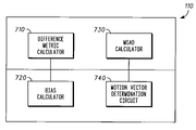
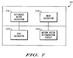
- FIG. 7 is an exemplary block diagram of a fast predictive motion search motion estimation circuit 110 according to one embodiment.
- the motion estimation circuit 110 can include a difference metric calculator 710 , a bias calculator 720 , a MSAD calculator 730 , and a motion vector determination circuit 740 .
- the circuits operate in accordance with their like functions described with respect to the flowchart 600 .
- a fast predictive motion search method can be performed by two stages.
- the 7 MVP candidates can be computed as described above.
- all MV candidates can be evaluated according to the search pattern in FIG. 3 and the exit criteria can be employed to break out of the MVP or go into the capture mode.
- the search can be performed at and around the MVP depicted in FIG. 4 using the same search pattern in FIG. 3 and the same exit criteria.
- the best MV from the first stage can be chosen and a search can be performed in a spiral fashion depicted in FIG. 5 . The spiral can be re-centered and reset the index can be reset to zero whenever a better match is found.
- the process can be continued until one of the three exit criteria are found.
- the disclosed invention can achieve a high degree of compression efficiency while keeping the complexity low.
- the complexity can be similar to the complexity of APDZS and PMVFAST. However, the achieved quality is higher.
- the present invention achieves about 0.6% better compression efficiency for a fixed video quality. This number was obtained after averaging over 24 different QCIF video sequences.
- One application for this invention is in real time video encoders on hand held devices.
- the typical bandwidth of such encoded video is in the range 32 kbps to 512 kbps and the typical video frame size is QCIF and CIF.
- the method of this invention is preferably implemented on a programmed processor.
- the video compression system 100 , the motion estimation circuitry 110 , and other elements may also be implemented on a general purpose or special purpose computer, a programmed microprocessor or microcontroller and peripheral integrated circuit elements, an ASIC or other integrated circuit, a hardware electronic or logic circuit such as a discrete element circuit, a programmable logic device such as a PLD, PLA, FPGA or PAL, or the like.
- any device on which resides a finite state machine capable of implementing the flowcharts shown in the Figures and the methods described may be used to implement the processor functions of this invention.
Abstract
Description
Where, Bc is the block in the current image frame and Bp is a block in the previous image frame. The indices m and n index the pixels within a block of N rows and M columns. A small SAD value corresponds to a good block match and a large SAD value corresponds to a poor block match. Unfortunately, FSME becomes prohibitive as the search window is increased. Another problem exists for FSME in that use of the SAD metric requires an excessive number of bits needed to encode motion vectors which results in compression inefficiency.
THRESH 1=SAD 1+OFFSET,
Where OFFSET may nominally be set to 500
Where SAD1 is given by the equation:
-
- CONDITION 1: The MSAD is below a threshold THRESH4, given by:
THRESH 4 =A*Q+B- Where Q is the quantization step size used by the encoder for the current MB, A and B are constants. In the preferred embodiment, A=8 and B=0.
- CONDITION 2: The maximum number of candidates, N, have already been considered in
stage 2. In the preferred embodiment, N=30. - CONDITION 3: These is no improvement in the minimum MSAD (MMSAD) during the last M candidate MVs. Here M is a function of the index of the position of the last MV candidate in the spiral search pattern. For example, the search starts from
index 0. It then spirals around points 1, 2, 3, . . . . Whenever a better MV is found, the spiral search pattern gets re-centered around this new MV and the index starts from 0 once again. This index is used to determine the value of M. In the preferred embodiment, M is chosen from the set of values {4, 4, 4, 4, 4, 4, 4, 4, 4, 5, 5, 5, 5, 6, 6, 6, 6, 7, 7, 7, 7, 7, 7, 8, 8, 8, 8, 8, 9, 9} based on the index.
- CONDITION 1: The MSAD is below a threshold THRESH4, given by:
MSAD=SAD+Bias
MSAD=SAD+C*(|MV X −PMV X |+|MV Y −PMV Y|)
C*((MV x −PMV x)2+(MV y −PMV y)2)
-
- If (SAD<THRESH5)
MSAD=SAD−THRESH 6 - Else
MSAD=SAD+C*(|PMV x |+|PMV Y|) - Endif
C, PMVx and PMVy are as described earlier.
THRESH 5 =D*Q+E
THRESH 6=F
- If (SAD<THRESH5)
Claims (28)
Priority Applications (7)
| Application Number | Priority Date | Filing Date | Title |
|---|---|---|---|
| US10/213,652 US7023921B2 (en) | 2002-08-06 | 2002-08-06 | Method and apparatus for determining block match quality |
| KR1020057002130A KR101018564B1 (en) | 2002-08-06 | 2003-07-25 | Method and apparatus for determining block match quality |
| MXPA05001448A MXPA05001448A (en) | 2002-08-06 | 2003-07-25 | Method and apparatus for determining block match quality. |
| PCT/US2003/023204 WO2004014060A2 (en) | 2002-08-06 | 2003-07-25 | Method and apparatus for determining block match quality |
| AU2003256763A AU2003256763A1 (en) | 2002-08-06 | 2003-07-25 | Method and apparatus for determining block match quality |
| EP03766904.1A EP1574038B1 (en) | 2002-08-06 | 2003-07-25 | Method and apparatus for estimating a motion vector |
| RU2005106280/09A RU2381630C2 (en) | 2002-08-06 | 2003-07-25 | Method and device for determining block conformity quality |
Applications Claiming Priority (1)
| Application Number | Priority Date | Filing Date | Title |
|---|---|---|---|
| US10/213,652 US7023921B2 (en) | 2002-08-06 | 2002-08-06 | Method and apparatus for determining block match quality |
Publications (2)
| Publication Number | Publication Date |
|---|---|
| US20040028134A1 US20040028134A1 (en) | 2004-02-12 |
| US7023921B2 true US7023921B2 (en) | 2006-04-04 |
Family
ID=31494499
Family Applications (1)
| Application Number | Title | Priority Date | Filing Date |
|---|---|---|---|
| US10/213,652 Active 2024-09-17 US7023921B2 (en) | 2002-08-06 | 2002-08-06 | Method and apparatus for determining block match quality |
Country Status (7)
| Country | Link |
|---|---|
| US (1) | US7023921B2 (en) |
| EP (1) | EP1574038B1 (en) |
| KR (1) | KR101018564B1 (en) |
| AU (1) | AU2003256763A1 (en) |
| MX (1) | MXPA05001448A (en) |
| RU (1) | RU2381630C2 (en) |
| WO (1) | WO2004014060A2 (en) |
Cited By (14)
| Publication number | Priority date | Publication date | Assignee | Title |
|---|---|---|---|---|
| US20050175105A1 (en) * | 2004-02-06 | 2005-08-11 | Industrial Technology Research Institute | Block matching method for video compression |
| US20060161648A1 (en) * | 2002-10-17 | 2006-07-20 | Bmc Software, Inc. | System and Method for Statistical Performance Monitoring |
| US20070014477A1 (en) * | 2005-07-18 | 2007-01-18 | Alexander Maclnnis | Method and system for motion compensation |
| US20100290531A1 (en) * | 2009-05-18 | 2010-11-18 | Canon Kabushiki Kaisha | Method and device for coding a video sequence |
| US20110002390A1 (en) * | 2009-07-03 | 2011-01-06 | Yi-Jen Chiu | Methods and systems for motion vector derivation at a video decoder |
| US20110002387A1 (en) * | 2009-07-03 | 2011-01-06 | Yi-Jen Chiu | Techniques for motion estimation |
| US20110002389A1 (en) * | 2009-07-03 | 2011-01-06 | Lidong Xu | Methods and systems to estimate motion based on reconstructed reference frames at a video decoder |
| US20110090964A1 (en) * | 2009-10-20 | 2011-04-21 | Lidong Xu | Methods and apparatus for adaptively choosing a search range for motion estimation |
| US20130039427A1 (en) * | 2008-07-09 | 2013-02-14 | Marvell World Trade Ltd. | Method and Apparatus for Periodic Structure Handling for Motion Compensation |
| TWI403172B (en) * | 2010-08-27 | 2013-07-21 | Himax Tech Ltd | Method of estimating a motion vector |
| US8711941B2 (en) | 2010-10-29 | 2014-04-29 | Lsi Corporation | Motion estimation for a video transcoder |
| US9509995B2 (en) | 2010-12-21 | 2016-11-29 | Intel Corporation | System and method for enhanced DMVD processing |
| US10200709B2 (en) | 2012-03-16 | 2019-02-05 | Qualcomm Incorporated | High-level syntax extensions for high efficiency video coding |
| US10250885B2 (en) | 2000-12-06 | 2019-04-02 | Intel Corporation | System and method for intracoding video data |
Families Citing this family (52)
| Publication number | Priority date | Publication date | Assignee | Title |
|---|---|---|---|---|
| US6700996B1 (en) * | 2000-06-07 | 2004-03-02 | Intel Corporation | Adaptive early exit techniques in image correlation |
| US6907080B1 (en) * | 2000-06-07 | 2005-06-14 | Intel Corporation | Adaptive early exit techniques in image correlation |
| US6654502B1 (en) * | 2000-06-07 | 2003-11-25 | Intel Corporation | Adaptive early exit techniques in image correlation |
| GB0227566D0 (en) * | 2002-11-26 | 2002-12-31 | British Telecomm | Method and system for estimating global motion in video sequences |
| GB0227570D0 (en) * | 2002-11-26 | 2002-12-31 | British Telecomm | Method and system for estimating global motion in video sequences |
| US8000392B1 (en) | 2004-02-27 | 2011-08-16 | Vbrick Systems, Inc. | Phase correlation based motion estimation in hybrid video compression |
| US7697610B2 (en) * | 2004-09-13 | 2010-04-13 | Microsoft Corporation | Variable block size early termination for video coding |
| US8446964B2 (en) * | 2005-07-18 | 2013-05-21 | Broadcom Corporation | Method and system for noise reduction with a motion compensated temporal filter |
| US7881384B2 (en) | 2005-08-05 | 2011-02-01 | Lsi Corporation | Method and apparatus for H.264 to MPEG-2 video transcoding |
| US8045618B2 (en) | 2005-08-05 | 2011-10-25 | Lsi Corporation | Method and apparatus for MPEG-2 to VC-1 video transcoding |
| US7903739B2 (en) * | 2005-08-05 | 2011-03-08 | Lsi Corporation | Method and apparatus for VC-1 to MPEG-2 video transcoding |
| US7912127B2 (en) * | 2005-08-05 | 2011-03-22 | Lsi Corporation | H.264 to VC-1 and VC-1 to H.264 transcoding |
| US8208540B2 (en) | 2005-08-05 | 2012-06-26 | Lsi Corporation | Video bitstream transcoding method and apparatus |
| KR20070069615A (en) | 2005-12-28 | 2007-07-03 | 삼성전자주식회사 | Motion estimator and motion estimating method |
| US8265145B1 (en) * | 2006-01-13 | 2012-09-11 | Vbrick Systems, Inc. | Management and selection of reference frames for long term prediction in motion estimation |
| KR100949974B1 (en) | 2006-03-30 | 2010-03-29 | 엘지전자 주식회사 | A method and apparatus for decoding/encoding a video signal |
| WO2007148906A1 (en) * | 2006-06-19 | 2007-12-27 | Lg Electronics, Inc. | Method and apparatus for processing a vedeo signal |
| TW200820791A (en) | 2006-08-25 | 2008-05-01 | Lg Electronics Inc | A method and apparatus for decoding/encoding a video signal |
| US7865030B2 (en) * | 2006-09-13 | 2011-01-04 | Broadcom Corporation | Method and system for motion compensated temporal filtering using both FIR and IIR filtering |
| US8509313B2 (en) * | 2006-10-10 | 2013-08-13 | Texas Instruments Incorporated | Video error concealment |
| KR100870554B1 (en) * | 2007-01-08 | 2008-11-27 | 한양대학교 산학협력단 | Motion compensated temporal filtering method for efficient wavelet-based scalable video coding and record-medium for executing method thereof |
| US8184696B1 (en) * | 2007-09-11 | 2012-05-22 | Xilinx, Inc. | Method and apparatus for an adaptive systolic array structure |
| KR100939917B1 (en) | 2008-03-07 | 2010-02-03 | 에스케이 텔레콤주식회사 | Encoding system using motion estimation and encoding method using motion estimation |
| US8358696B2 (en) * | 2008-12-31 | 2013-01-22 | Intel Corporation | Motion estimation techniques |
| KR101452859B1 (en) | 2009-08-13 | 2014-10-23 | 삼성전자주식회사 | Method and apparatus for encoding and decoding motion vector |
| US8411750B2 (en) * | 2009-10-30 | 2013-04-02 | Qualcomm Incorporated | Global motion parameter estimation using block-based motion vectors |
| KR101768207B1 (en) * | 2010-01-19 | 2017-08-16 | 삼성전자주식회사 | Method and apparatus for encoding/decoding motion vector based on reduced motion vector predictor candidates |
| WO2011131089A1 (en) * | 2010-04-22 | 2011-10-27 | Mediatek Inc. | Motion prediction method |
| PL2698999T3 (en) | 2011-04-12 | 2017-10-31 | Sun Patent Trust | Motion-video encoding method, motion-video encoding apparatus, motion-video decoding method, motion-video decoding apparatus, and motion-video encoding/decoding apparatus |
| WO2012160803A1 (en) | 2011-05-24 | 2012-11-29 | パナソニック株式会社 | Image encoding method, image encoding apparatus, image decoding method, image decoding apparatus, and image encoding/decoding apparatus |
| US9485518B2 (en) | 2011-05-27 | 2016-11-01 | Sun Patent Trust | Decoding method and apparatus with candidate motion vectors |
| PL2717575T3 (en) * | 2011-05-27 | 2019-03-29 | Sun Patent Trust | Image decoding method and image decoding device |
| SG194746A1 (en) | 2011-05-31 | 2013-12-30 | Kaba Gmbh | Image encoding method, image encoding device, image decoding method, image decoding device, and image encoding/decoding device |
| EP2717579B1 (en) | 2011-05-31 | 2020-01-22 | Sun Patent Trust | Video decoding method and video decoding device |
| KR101900986B1 (en) | 2011-06-30 | 2018-09-20 | 선 페이턴트 트러스트 | Image decoding method, image encoding method, image decoding device, image encoding device, and image encoding/decoding device |
| JPWO2013018369A1 (en) | 2011-08-03 | 2015-03-05 | パナソニック インテレクチュアル プロパティ コーポレーション オブアメリカPanasonic Intellectual Property Corporation of America | Moving picture coding method, moving picture coding apparatus, moving picture decoding method, moving picture decoding apparatus, and moving picture coding / decoding apparatus |
| RU2477891C1 (en) * | 2011-09-02 | 2013-03-20 | Открытое акционерное общество "Концерн радиостроения "Вега" | Method of detecting modification of electronic image (versions) |
| BR112014008403B1 (en) | 2011-10-19 | 2022-05-10 | Sun Patent Trust | Image encoding method, image encoding apparatus, image decoding method, and image decoding apparatus |
| EP2800371A4 (en) * | 2011-12-28 | 2015-08-12 | Jvc Kenwood Corp | Video encoding device, video encoding method and video encoding program, and video decoding device, video decoding method and video decoding program |
| TWI580260B (en) * | 2012-01-18 | 2017-04-21 | Jvc Kenwood Corp | Dynamic image decoding device, dynamic image decoding method, and dynamic image decoding program |
| US9503720B2 (en) * | 2012-03-16 | 2016-11-22 | Qualcomm Incorporated | Motion vector coding and bi-prediction in HEVC and its extensions |
| RU2629359C1 (en) * | 2013-01-18 | 2017-08-29 | ДжейВиСи КЕНВУД КОРПОРЕЙШН | Device and method for decoding a moving image, long-term computer recorded media recording to storage a program of decoding a moving image |
| GB2534591A (en) * | 2015-01-29 | 2016-08-03 | Nokia Technologies Oy | Video encoding and decoding |
| US10999602B2 (en) | 2016-12-23 | 2021-05-04 | Apple Inc. | Sphere projected motion estimation/compensation and mode decision |
| US11259046B2 (en) | 2017-02-15 | 2022-02-22 | Apple Inc. | Processing of equirectangular object data to compensate for distortion by spherical projections |
| US10924747B2 (en) | 2017-02-27 | 2021-02-16 | Apple Inc. | Video coding techniques for multi-view video |
| CN110495177B (en) * | 2017-04-13 | 2023-10-20 | 松下电器(美国)知识产权公司 | Decoding device, decoding method, and storage medium |
| US11093752B2 (en) | 2017-06-02 | 2021-08-17 | Apple Inc. | Object tracking in multi-view video |
| US10754242B2 (en) | 2017-06-30 | 2020-08-25 | Apple Inc. | Adaptive resolution and projection format in multi-direction video |
| CN109063694B (en) * | 2018-09-12 | 2021-07-02 | 北京科技大学 | Video target detection and identification method |
| CN110312124B (en) * | 2019-07-31 | 2020-09-08 | 中国矿业大学 | Mobile inspection video quality correction method based on saliency multi-feature fusion |
| WO2022040846A1 (en) * | 2020-08-24 | 2022-03-03 | 华为技术有限公司 | Method for optimizing motion vector and related device |
Citations (9)
| Publication number | Priority date | Publication date | Assignee | Title |
|---|---|---|---|---|
| US5428403A (en) * | 1991-09-30 | 1995-06-27 | U.S. Philips Corporation | Motion vector estimation, motion picture encoding and storage |
| US5594504A (en) * | 1994-07-06 | 1997-01-14 | Lucent Technologies Inc. | Predictive video coding using a motion vector updating routine |
| US5721595A (en) * | 1996-06-19 | 1998-02-24 | United Microelectronics Corporation | Motion estimation block matching process and apparatus for video image processing |
| US5835163A (en) * | 1995-12-21 | 1998-11-10 | Siemens Corporate Research, Inc. | Apparatus for detecting a cut in a video |
| US6037986A (en) * | 1996-07-16 | 2000-03-14 | Divicom Inc. | Video preprocessing method and apparatus with selective filtering based on motion detection |
| US20010002205A1 (en) * | 1997-06-18 | 2001-05-31 | Tandberg Television Asa | Encoding digital signals |
| US6532264B1 (en) * | 2000-03-27 | 2003-03-11 | Teranex, Inc. | Processing sequential video images to detect image motion among interlaced video fields or progressive video images |
| US6549576B1 (en) * | 1999-02-15 | 2003-04-15 | Nec Corporation | Motion vector detecting method and apparatus |
| US6842483B1 (en) * | 2000-09-11 | 2005-01-11 | The Hong Kong University Of Science And Technology | Device, method and digital video encoder for block-matching motion estimation |
Family Cites Families (3)
| Publication number | Priority date | Publication date | Assignee | Title |
|---|---|---|---|---|
| DE3727530A1 (en) * | 1987-08-18 | 1989-03-02 | Philips Patentverwaltung | Method for determining motion vectors |
| US5847776A (en) | 1996-06-24 | 1998-12-08 | Vdonet Corporation Ltd. | Method for entropy constrained motion estimation and coding of motion vectors with increased search range |
| US5825930A (en) * | 1997-03-05 | 1998-10-20 | Samsung Electronics Co., Ltd. | Motion estimating method |
-
2002
- 2002-08-06 US US10/213,652 patent/US7023921B2/en active Active
-
2003
- 2003-07-25 MX MXPA05001448A patent/MXPA05001448A/en active IP Right Grant
- 2003-07-25 AU AU2003256763A patent/AU2003256763A1/en not_active Abandoned
- 2003-07-25 EP EP03766904.1A patent/EP1574038B1/en not_active Expired - Lifetime
- 2003-07-25 KR KR1020057002130A patent/KR101018564B1/en active IP Right Grant
- 2003-07-25 WO PCT/US2003/023204 patent/WO2004014060A2/en not_active Application Discontinuation
- 2003-07-25 RU RU2005106280/09A patent/RU2381630C2/en not_active IP Right Cessation
Patent Citations (9)
| Publication number | Priority date | Publication date | Assignee | Title |
|---|---|---|---|---|
| US5428403A (en) * | 1991-09-30 | 1995-06-27 | U.S. Philips Corporation | Motion vector estimation, motion picture encoding and storage |
| US5594504A (en) * | 1994-07-06 | 1997-01-14 | Lucent Technologies Inc. | Predictive video coding using a motion vector updating routine |
| US5835163A (en) * | 1995-12-21 | 1998-11-10 | Siemens Corporate Research, Inc. | Apparatus for detecting a cut in a video |
| US5721595A (en) * | 1996-06-19 | 1998-02-24 | United Microelectronics Corporation | Motion estimation block matching process and apparatus for video image processing |
| US6037986A (en) * | 1996-07-16 | 2000-03-14 | Divicom Inc. | Video preprocessing method and apparatus with selective filtering based on motion detection |
| US20010002205A1 (en) * | 1997-06-18 | 2001-05-31 | Tandberg Television Asa | Encoding digital signals |
| US6549576B1 (en) * | 1999-02-15 | 2003-04-15 | Nec Corporation | Motion vector detecting method and apparatus |
| US6532264B1 (en) * | 2000-03-27 | 2003-03-11 | Teranex, Inc. | Processing sequential video images to detect image motion among interlaced video fields or progressive video images |
| US6842483B1 (en) * | 2000-09-11 | 2005-01-11 | The Hong Kong University Of Science And Technology | Device, method and digital video encoder for block-matching motion estimation |
Cited By (28)
| Publication number | Priority date | Publication date | Assignee | Title |
|---|---|---|---|---|
| US10701368B2 (en) | 2000-12-06 | 2020-06-30 | Intel Corporation | System and method for intracoding video data |
| US10250885B2 (en) | 2000-12-06 | 2019-04-02 | Intel Corporation | System and method for intracoding video data |
| US20060161648A1 (en) * | 2002-10-17 | 2006-07-20 | Bmc Software, Inc. | System and Method for Statistical Performance Monitoring |
| US8000932B2 (en) * | 2002-10-17 | 2011-08-16 | Bmc Software, Inc. | System and method for statistical performance monitoring |
| US20050175105A1 (en) * | 2004-02-06 | 2005-08-11 | Industrial Technology Research Institute | Block matching method for video compression |
| US8588513B2 (en) * | 2005-07-18 | 2013-11-19 | Broadcom Corporation | Method and system for motion compensation |
| US20070014477A1 (en) * | 2005-07-18 | 2007-01-18 | Alexander Maclnnis | Method and system for motion compensation |
| US9210445B2 (en) * | 2008-07-09 | 2015-12-08 | Marvell World Trade Ltd. | Method and apparatus for periodic structure handling for motion compensation |
| US20130039427A1 (en) * | 2008-07-09 | 2013-02-14 | Marvell World Trade Ltd. | Method and Apparatus for Periodic Structure Handling for Motion Compensation |
| US20100290531A1 (en) * | 2009-05-18 | 2010-11-18 | Canon Kabushiki Kaisha | Method and device for coding a video sequence |
| US8743961B2 (en) * | 2009-05-18 | 2014-06-03 | Canon Kabushiki Kaisha | Method and device for coding a video sequence including an improved motion vector calculation |
| US9955179B2 (en) | 2009-07-03 | 2018-04-24 | Intel Corporation | Methods and systems for motion vector derivation at a video decoder |
| US10404994B2 (en) | 2009-07-03 | 2019-09-03 | Intel Corporation | Methods and systems for motion vector derivation at a video decoder |
| US11765380B2 (en) | 2009-07-03 | 2023-09-19 | Tahoe Research, Ltd. | Methods and systems for motion vector derivation at a video decoder |
| US10863194B2 (en) | 2009-07-03 | 2020-12-08 | Intel Corporation | Methods and systems for motion vector derivation at a video decoder |
| US8917769B2 (en) * | 2009-07-03 | 2014-12-23 | Intel Corporation | Methods and systems to estimate motion based on reconstructed reference frames at a video decoder |
| US20110002390A1 (en) * | 2009-07-03 | 2011-01-06 | Yi-Jen Chiu | Methods and systems for motion vector derivation at a video decoder |
| US9445103B2 (en) | 2009-07-03 | 2016-09-13 | Intel Corporation | Methods and apparatus for adaptively choosing a search range for motion estimation |
| US20110002387A1 (en) * | 2009-07-03 | 2011-01-06 | Yi-Jen Chiu | Techniques for motion estimation |
| US9538197B2 (en) | 2009-07-03 | 2017-01-03 | Intel Corporation | Methods and systems to estimate motion based on reconstructed reference frames at a video decoder |
| US9654792B2 (en) | 2009-07-03 | 2017-05-16 | Intel Corporation | Methods and systems for motion vector derivation at a video decoder |
| US20110002389A1 (en) * | 2009-07-03 | 2011-01-06 | Lidong Xu | Methods and systems to estimate motion based on reconstructed reference frames at a video decoder |
| US20110090964A1 (en) * | 2009-10-20 | 2011-04-21 | Lidong Xu | Methods and apparatus for adaptively choosing a search range for motion estimation |
| US8462852B2 (en) | 2009-10-20 | 2013-06-11 | Intel Corporation | Methods and apparatus for adaptively choosing a search range for motion estimation |
| TWI403172B (en) * | 2010-08-27 | 2013-07-21 | Himax Tech Ltd | Method of estimating a motion vector |
| US8711941B2 (en) | 2010-10-29 | 2014-04-29 | Lsi Corporation | Motion estimation for a video transcoder |
| US9509995B2 (en) | 2010-12-21 | 2016-11-29 | Intel Corporation | System and method for enhanced DMVD processing |
| US10200709B2 (en) | 2012-03-16 | 2019-02-05 | Qualcomm Incorporated | High-level syntax extensions for high efficiency video coding |
Also Published As
| Publication number | Publication date |
|---|---|
| KR101018564B1 (en) | 2011-03-03 |
| RU2005106280A (en) | 2005-10-10 |
| WO2004014060B1 (en) | 2007-08-02 |
| US20040028134A1 (en) | 2004-02-12 |
| AU2003256763A1 (en) | 2004-02-23 |
| WO2004014060A2 (en) | 2004-02-12 |
| KR20050056956A (en) | 2005-06-16 |
| EP1574038A4 (en) | 2009-12-16 |
| RU2381630C2 (en) | 2010-02-10 |
| EP1574038B1 (en) | 2013-08-21 |
| WO2004014060A3 (en) | 2007-06-21 |
| MXPA05001448A (en) | 2005-09-30 |
| AU2003256763A8 (en) | 2004-02-23 |
| EP1574038A2 (en) | 2005-09-14 |
Similar Documents
| Publication | Publication Date | Title |
|---|---|---|
| US7023921B2 (en) | Method and apparatus for determining block match quality | |
| US7463687B2 (en) | Method and apparatus for performing high quality fast predictive motion search | |
| US9621917B2 (en) | Continuous block tracking for temporal prediction in video encoding | |
| KR100534207B1 (en) | Device and method for motion estimating of video coder | |
| EP1960967B1 (en) | Motion estimation using prediction guided decimated search | |
| US8040948B2 (en) | Method and system for coding moving image signals, corresponding computer program product | |
| Grecos et al. | Fast inter mode prediction for P slices in the H264 video coding standard | |
| KR100739281B1 (en) | Motion estimation method and appratus | |
| US20070268964A1 (en) | Unit co-location-based motion estimation | |
| US20150172687A1 (en) | Multiple-candidate motion estimation with advanced spatial filtering of differential motion vectors | |
| KR100560843B1 (en) | Method and Apparatus for Determining Search Range for Adaptive Motion Vector for Use in Video Encoder | |
| JP2007124408A (en) | Motion vector detector and motion vector detecting method | |
| US7433407B2 (en) | Method for hierarchical motion estimation | |
| WO2020129681A1 (en) | Encryption device and program | |
| KR100859073B1 (en) | Motion estimation method | |
| KR0180171B1 (en) | Block motion estimation method | |
| JP2004260251A (en) | Apparatus and program of detecting motion vector | |
| KR19990058255A (en) | Video compression method using 1/4 pixel motion vector. | |
| JP2009296443A (en) | Vector search range limiting apparatus, and moving image encoding device | |
| Wu et al. | Linear predicted hexagonal search algorithm with moments | |
| KR20000037945A (en) | Apparatus for efficiently tracing motion considering contour of image |
Legal Events
| Date | Code | Title | Description |
|---|---|---|---|
| AS | Assignment |
Owner name: MOTOROLA, INC., ILLINOIS Free format text: ASSIGNMENT OF ASSIGNORS INTEREST;ASSIGNORS:SUBRAMANIYAN, RAGHAVAN;GANDHI, BHAVAN;REEL/FRAME:013186/0975 Effective date: 20020802 |
|
| STCF | Information on status: patent grant |
Free format text: PATENTED CASE |
|
| FPAY | Fee payment |
Year of fee payment: 4 |
|
| AS | Assignment |
Owner name: MOTOROLA MOBILITY, INC, ILLINOIS Free format text: ASSIGNMENT OF ASSIGNORS INTEREST;ASSIGNOR:MOTOROLA, INC;REEL/FRAME:025673/0558 Effective date: 20100731 |
|
| AS | Assignment |
Owner name: MOTOROLA MOBILITY LLC, ILLINOIS Free format text: CHANGE OF NAME;ASSIGNOR:MOTOROLA MOBILITY, INC.;REEL/FRAME:029216/0282 Effective date: 20120622 |
|
| FPAY | Fee payment |
Year of fee payment: 8 |
|
| AS | Assignment |
Owner name: GOOGLE TECHNOLOGY HOLDINGS LLC, CALIFORNIA Free format text: ASSIGNMENT OF ASSIGNORS INTEREST;ASSIGNOR:MOTOROLA MOBILITY LLC;REEL/FRAME:034453/0001 Effective date: 20141028 |
|
| MAFP | Maintenance fee payment |
Free format text: PAYMENT OF MAINTENANCE FEE, 12TH YEAR, LARGE ENTITY (ORIGINAL EVENT CODE: M1553) Year of fee payment: 12 |