US7026724B1 - Method for limiting current of starter/alternator in generator mode - Google Patents
Method for limiting current of starter/alternator in generator mode Download PDFInfo
- Publication number
- US7026724B1 US7026724B1 US10/206,936 US20693602A US7026724B1 US 7026724 B1 US7026724 B1 US 7026724B1 US 20693602 A US20693602 A US 20693602A US 7026724 B1 US7026724 B1 US 7026724B1
- Authority
- US
- United States
- Prior art keywords
- starter
- alternator
- output voltage
- current value
- output
- Prior art date
- Legal status (The legal status is an assumption and is not a legal conclusion. Google has not performed a legal analysis and makes no representation as to the accuracy of the status listed.)
- Expired - Fee Related, expires
Links
- 239000007858 starting material Substances 0.000 title claims abstract description 39
- 238000000034 method Methods 0.000 title claims description 11
- 230000004044 response Effects 0.000 claims abstract description 5
- 238000009434 installation Methods 0.000 claims abstract 2
- 238000012544 monitoring process Methods 0.000 claims 3
- 230000007423 decrease Effects 0.000 abstract description 3
- 239000003054 catalyst Substances 0.000 description 2
- 230000001276 controlling effect Effects 0.000 description 2
- 230000007257 malfunction Effects 0.000 description 2
- 230000001105 regulatory effect Effects 0.000 description 2
- 230000003213 activating effect Effects 0.000 description 1
- 230000001351 cycling effect Effects 0.000 description 1
- 230000003247 decreasing effect Effects 0.000 description 1
- 238000010586 diagram Methods 0.000 description 1
- 239000012530 fluid Substances 0.000 description 1
- 230000004043 responsiveness Effects 0.000 description 1
- 230000000717 retained effect Effects 0.000 description 1
Images


Classifications
-
- H—ELECTRICITY
- H02—GENERATION; CONVERSION OR DISTRIBUTION OF ELECTRIC POWER
- H02P—CONTROL OR REGULATION OF ELECTRIC MOTORS, ELECTRIC GENERATORS OR DYNAMO-ELECTRIC CONVERTERS; CONTROLLING TRANSFORMERS, REACTORS OR CHOKE COILS
- H02P29/00—Arrangements for regulating or controlling electric motors, appropriate for both AC and DC motors
- H02P29/02—Providing protection against overload without automatic interruption of supply
- H02P29/032—Preventing damage to the motor, e.g. setting individual current limits for different drive conditions
Definitions
- the invention relates to the field of automotive electrical systems. Specifically, the invention is directed to a method of limiting current supplied by a starter/alternator in the generator mode in the circumstance where a system malfunction has occurred and current demand placed on the generator has exceeded the load capacity of the starter/alternator.
- an element of the trend involves the combination of the alternator and starter into a single IC engine driven unit.
- This combined starter/alternator can be driven either directly on the crankshaft of the IC engine as a part of the flywheel on one end or the balancer on the other.
- the starter/alternator can be mounted for gear, belt, or chain drive from the crankshaft of other IC engine driven component (waterpump/A/C compressor/power steering pump, etc.)
- the starter/alternator has become more powerful not only for increasing power (current and voltage) but also for more rapid and more frequent starting cycles of the IC engine as enhanced operating efficiencies are sought. In pursuit of these goals, the starter/alternator has become more sophisticated in its control systems and its responsiveness to system requirements for both starter functions and generating functions. In older fixed output generators (i.e., 1000 watts in a range of pre-selected engines speeds), the excess load would simply divert to the battery, or other electrical power storage device, similarly excess output would also divert.
- the present invention is directed to controlling the current output of a combined starter/alternator in response to demand loads such that the starter/alternator does not overload and fail.
- the current in the starter/alternator motor phases and/or the output current from the starter/alternator inverter is monitored. Once the monitored current reaches a predetermined threshold, the output voltage of the starter/alternator is regulated and reduced to maintain the output at the predetermined threshold level. Once the load demand decreases, the output voltage is increased back to the original set point.
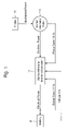
- FIG. 1 shows a block diagram of the necessary sensors and hardware to accomplish the present method.
- FIG. 2 shows a flow chart of decision making for the method used by the system controller in the present invention to determine threshold output current and to regulate and set associated output voltage to prevent starter/alternator overload.
- the present invention is directed to a method of controlling a starter/alternator 10 associated with an IC engine 12 .
- the starter/alternator 10 and IC engine 12 form a part of the motive system for a vehicle that has additional electrical components that create electrical load for the starter/alternator 10 to supply.
- the inverter/controller 18 controls the output of the starter/alternator as the output flows into the electrical system of the vehicle that also includes an electrical storage device 20 (battery).
- the controller 18 monitors the phase currents and output current of the starter/alternator 10 .
- electrical load i.e., A/C blowers switched to high for defrost and, at the same time, activating seat heaters, rear window heater, rear side view mirror heaters, and fast acting catalyst start-up heater
- the output of the starter/alternator is increased by the controller accordingly.
- the controller detects current exceeding a predetermined threshold, the output voltage is reduced by a predetermined increment, ie, 0.5 volts, the respective phase and output currents are again monitored to determine if they still exceed a predetermined threshold, if yes, the output voltage is again stepped down a predetermined amount.
- the output voltage is monitored and increased as the current demand decreases. I.e., as the catalyst quick start heater deactivates and the window and mirror heaters automatically cycle off after 3–5 minutes of operation.
- the system controller 18 regulates the output voltage that is stepped incrementally back to the original set point for output voltage.
- the method of the present invention can be activated in response to a rapidly increasing demand for electrical power created by load cycling into the system, or by heavy charging demands of a depleted storage device, or by a failed electrical component (shorted or other load generating malfunction).
- the starter/alternator is prevented from overloading and itself failing.
- the starter/alternator output voltage is regulated to keep output current from reaching beyond predetermined limits and thereby preserving the starter/alternator from overload failure.
Abstract
Description
Claims (3)
Priority Applications (1)
| Application Number | Priority Date | Filing Date | Title |
|---|---|---|---|
| US10/206,936 US7026724B1 (en) | 2002-07-30 | 2002-07-30 | Method for limiting current of starter/alternator in generator mode |
Applications Claiming Priority (1)
| Application Number | Priority Date | Filing Date | Title |
|---|---|---|---|
| US10/206,936 US7026724B1 (en) | 2002-07-30 | 2002-07-30 | Method for limiting current of starter/alternator in generator mode |
Publications (1)
| Publication Number | Publication Date |
|---|---|
| US7026724B1 true US7026724B1 (en) | 2006-04-11 |
Family
ID=36127715
Family Applications (1)
| Application Number | Title | Priority Date | Filing Date |
|---|---|---|---|
| US10/206,936 Expired - Fee Related US7026724B1 (en) | 2002-07-30 | 2002-07-30 | Method for limiting current of starter/alternator in generator mode |
Country Status (1)
| Country | Link |
|---|---|
| US (1) | US7026724B1 (en) |
Cited By (8)
| Publication number | Priority date | Publication date | Assignee | Title |
|---|---|---|---|---|
| US20110018504A1 (en) * | 2009-07-23 | 2011-01-27 | C.E. Niehoff & Co. | System and method for generator phase signal monitoring and control |
| US20120234282A1 (en) * | 2010-02-25 | 2012-09-20 | Aisin Seiki Kabushiki Kaisha | Device and method for starting engine |
| US8283810B2 (en) | 2005-01-21 | 2012-10-09 | C.E. Niehoff & Co. | System and method for generator phase signal monitoring and control of electrical current distribution |
| US20120319470A1 (en) * | 2011-06-16 | 2012-12-20 | Renault S.A.S. | Method to supply an electric accessory of a motor vehicle comprising an electric battery to which said accessory is connected |
| US20150236703A1 (en) * | 2014-02-19 | 2015-08-20 | Remy Technologies, Llc | Method for load share balancing in a system of parallel-connected generators using selective load reduction |
| WO2016003731A1 (en) * | 2014-07-03 | 2016-01-07 | Caterpillar Inc. | Power management system having automatic calibration |
| US10124785B2 (en) | 2014-08-26 | 2018-11-13 | Cummins, Inc. | Electric engine accessory control |
| US10379143B2 (en) | 2014-07-23 | 2019-08-13 | Cummins, Inc. | System and method for improving a battery management and accumulator system |
Citations (5)
| Publication number | Priority date | Publication date | Assignee | Title |
|---|---|---|---|---|
| US4346341A (en) * | 1981-03-02 | 1982-08-24 | General Electric Company | Method and apparatus for automatic voltage reduction control |
| US4803376A (en) | 1986-09-11 | 1989-02-07 | Valeo | Control method for a reversible motor - generator electrical machine for a motor vehicle and control installation for the implementation of such method |
| US5168208A (en) | 1988-05-09 | 1992-12-01 | Onan Corporation | Microprocessor based integrated generator set controller apparatus and method |
| US5663632A (en) | 1995-07-17 | 1997-09-02 | Lucas Aerospace Power Equipment Corp. | Field current control for generator during build-up |
| US5801516A (en) | 1993-10-01 | 1998-09-01 | Lucas Aerospace Power Equipment Corp. | Drive overload protection circuit |
-
2002
- 2002-07-30 US US10/206,936 patent/US7026724B1/en not_active Expired - Fee Related
Patent Citations (5)
| Publication number | Priority date | Publication date | Assignee | Title |
|---|---|---|---|---|
| US4346341A (en) * | 1981-03-02 | 1982-08-24 | General Electric Company | Method and apparatus for automatic voltage reduction control |
| US4803376A (en) | 1986-09-11 | 1989-02-07 | Valeo | Control method for a reversible motor - generator electrical machine for a motor vehicle and control installation for the implementation of such method |
| US5168208A (en) | 1988-05-09 | 1992-12-01 | Onan Corporation | Microprocessor based integrated generator set controller apparatus and method |
| US5801516A (en) | 1993-10-01 | 1998-09-01 | Lucas Aerospace Power Equipment Corp. | Drive overload protection circuit |
| US5663632A (en) | 1995-07-17 | 1997-09-02 | Lucas Aerospace Power Equipment Corp. | Field current control for generator during build-up |
Cited By (17)
| Publication number | Priority date | Publication date | Assignee | Title |
|---|---|---|---|---|
| US8283810B2 (en) | 2005-01-21 | 2012-10-09 | C.E. Niehoff & Co. | System and method for generator phase signal monitoring and control of electrical current distribution |
| US8227941B2 (en) | 2009-07-23 | 2012-07-24 | C.E. Niehoff & Co. | System and method for generator phase signal monitoring and control |
| US8432069B2 (en) | 2009-07-23 | 2013-04-30 | C.E. Niehoff & Co. | System and method for generator phase signal monitoring and control |
| US20110018504A1 (en) * | 2009-07-23 | 2011-01-27 | C.E. Niehoff & Co. | System and method for generator phase signal monitoring and control |
| US20120234282A1 (en) * | 2010-02-25 | 2012-09-20 | Aisin Seiki Kabushiki Kaisha | Device and method for starting engine |
| US8578904B2 (en) * | 2010-02-25 | 2013-11-12 | Aisin Seiki Kabushiki Kaisha | Device and method for starting engine |
| US9446666B2 (en) * | 2011-06-16 | 2016-09-20 | Renault S.A.S. | Method to supply an electric accessory of a motor vehicle comprising an electric battery to which said accessory is connected |
| US20120319470A1 (en) * | 2011-06-16 | 2012-12-20 | Renault S.A.S. | Method to supply an electric accessory of a motor vehicle comprising an electric battery to which said accessory is connected |
| US20150236703A1 (en) * | 2014-02-19 | 2015-08-20 | Remy Technologies, Llc | Method for load share balancing in a system of parallel-connected generators using selective load reduction |
| WO2016003731A1 (en) * | 2014-07-03 | 2016-01-07 | Caterpillar Inc. | Power management system having automatic calibration |
| US9577558B2 (en) | 2014-07-03 | 2017-02-21 | Caterpillar Inc. | Power management system having automatic calibration |
| US10379143B2 (en) | 2014-07-23 | 2019-08-13 | Cummins, Inc. | System and method for improving a battery management and accumulator system |
| US11493541B2 (en) | 2014-07-23 | 2022-11-08 | Cummins, Inc. | System and method for improving a battery management and accumulator system |
| US11892482B2 (en) | 2014-07-23 | 2024-02-06 | Cummins Inc. | System and method for improving a battery management system |
| US10124785B2 (en) | 2014-08-26 | 2018-11-13 | Cummins, Inc. | Electric engine accessory control |
| US10882509B2 (en) | 2014-08-26 | 2021-01-05 | Cummins, Inc. | Electric engine accessory control |
| US11529941B2 (en) | 2014-08-26 | 2022-12-20 | Cummins Inc. | Electric engine accessory control |
Similar Documents
| Publication | Publication Date | Title |
|---|---|---|
| US7075273B2 (en) | Automotive electrical system configuration using a two bus structure | |
| US7106030B2 (en) | Field excitation for an alternator | |
| US6377031B1 (en) | Intelligent switch for power management | |
| JP2651030B2 (en) | Generator control device and control method, and vehicular generator control device and control method using the same | |
| US20040113494A1 (en) | Daytime running light control using an intelligent power management system | |
| US7358683B2 (en) | Automatic PWM controlled driver circuit and method | |
| US8914190B2 (en) | Method and device for operating a belt drive of a motor vehicle | |
| US7812467B1 (en) | Smart alternator load control | |
| US10870465B2 (en) | Power boost regulator | |
| JP2008511277A (en) | Voltage controller with overvoltage protection | |
| US20160339997A1 (en) | Power boost regulator | |
| JP2008507447A (en) | Device for supplying current to a fuel pump of an internal combustion engine of an automobile | |
| GB2327775A (en) | Cooling system for an internal combustion engine of a motor vehicle | |
| US7026724B1 (en) | Method for limiting current of starter/alternator in generator mode | |
| JP3642319B2 (en) | Control device for vehicle power supply | |
| US6801020B2 (en) | Current response controller for starter/alternator | |
| JPH0937597A (en) | Generator for vehicle | |
| US8493038B2 (en) | Vehicle-use power generation control apparatus and vehicle-use power generation control system | |
| JP4143648B2 (en) | Field winding AC rotating electrical machine | |
| EP1626476A1 (en) | Vehicle power supply control apparatus and vehicle power supply apparatus | |
| JP4209640B2 (en) | Boost power supply for engine generator | |
| GB2346596A (en) | Operation of a vehicle alternator | |
| US6633153B1 (en) | Under voltage protection for a starter/alternator | |
| JP5473949B2 (en) | Power generator with overvoltage monitoring function | |
| JP4911235B2 (en) | Vehicle power generation control device |
Legal Events
| Date | Code | Title | Description |
|---|---|---|---|
| AS | Assignment |
Owner name: DANA CORPORATION, OHIO Free format text: ASSIGNMENT OF ASSIGNORS INTEREST;ASSIGNOR:BLACKBURN, SCOTT EVART;REEL/FRAME:013154/0669 Effective date: 20020729 |
|
| AS | Assignment |
Owner name: DANA AUTOMOTIVE SYSTEMS GROUP, LLC, OHIO Free format text: ASSIGNMENT OF ASSIGNORS INTEREST;ASSIGNOR:DANA CORPORATION;REEL/FRAME:021998/0627 Effective date: 20080131 |
|
| REMI | Maintenance fee reminder mailed | ||
| LAPS | Lapse for failure to pay maintenance fees | ||
| STCH | Information on status: patent discontinuation |
Free format text: PATENT EXPIRED DUE TO NONPAYMENT OF MAINTENANCE FEES UNDER 37 CFR 1.362 |
|
| FP | Lapsed due to failure to pay maintenance fee |
Effective date: 20100411 |