US7028202B2 - Power adapter identification - Google Patents
Power adapter identification Download PDFInfo
- Publication number
- US7028202B2 US7028202B2 US10/202,136 US20213602A US7028202B2 US 7028202 B2 US7028202 B2 US 7028202B2 US 20213602 A US20213602 A US 20213602A US 7028202 B2 US7028202 B2 US 7028202B2
- Authority
- US
- United States
- Prior art keywords
- adapter
- electronic device
- contacts
- contact
- plug
- Prior art date
- Legal status (The legal status is an assumption and is not a legal conclusion. Google has not performed a legal analysis and makes no representation as to the accuracy of the status listed.)
- Active, expires
Links
Images


Classifications
-
- H—ELECTRICITY
- H01—ELECTRIC ELEMENTS
- H01R—ELECTRICALLY-CONDUCTIVE CONNECTIONS; STRUCTURAL ASSOCIATIONS OF A PLURALITY OF MUTUALLY-INSULATED ELECTRICAL CONNECTING ELEMENTS; COUPLING DEVICES; CURRENT COLLECTORS
- H01R29/00—Coupling parts for selective co-operation with a counterpart in different ways to establish different circuits, e.g. for voltage selection, for series-parallel selection, programmable connectors
-
- H—ELECTRICITY
- H01—ELECTRIC ELEMENTS
- H01R—ELECTRICALLY-CONDUCTIVE CONNECTIONS; STRUCTURAL ASSOCIATIONS OF A PLURALITY OF MUTUALLY-INSULATED ELECTRICAL CONNECTING ELEMENTS; COUPLING DEVICES; CURRENT COLLECTORS
- H01R31/00—Coupling parts supported only by co-operation with counterpart
- H01R31/06—Intermediate parts for linking two coupling parts, e.g. adapter
- H01R31/065—Intermediate parts for linking two coupling parts, e.g. adapter with built-in electric apparatus
-
- H—ELECTRICITY
- H01—ELECTRIC ELEMENTS
- H01R—ELECTRICALLY-CONDUCTIVE CONNECTIONS; STRUCTURAL ASSOCIATIONS OF A PLURALITY OF MUTUALLY-INSULATED ELECTRICAL CONNECTING ELEMENTS; COUPLING DEVICES; CURRENT COLLECTORS
- H01R13/00—Details of coupling devices of the kinds covered by groups H01R12/70 or H01R24/00 - H01R33/00
- H01R13/66—Structural association with built-in electrical component
- H01R13/6608—Structural association with built-in electrical component with built-in single component
- H01R13/6616—Structural association with built-in electrical component with built-in single component with resistor
-
- H—ELECTRICITY
- H01—ELECTRIC ELEMENTS
- H01R—ELECTRICALLY-CONDUCTIVE CONNECTIONS; STRUCTURAL ASSOCIATIONS OF A PLURALITY OF MUTUALLY-INSULATED ELECTRICAL CONNECTING ELEMENTS; COUPLING DEVICES; CURRENT COLLECTORS
- H01R2201/00—Connectors or connections adapted for particular applications
- H01R2201/06—Connectors or connections adapted for particular applications for computer periphery
-
- H—ELECTRICITY
- H01—ELECTRIC ELEMENTS
- H01R—ELECTRICALLY-CONDUCTIVE CONNECTIONS; STRUCTURAL ASSOCIATIONS OF A PLURALITY OF MUTUALLY-INSULATED ELECTRICAL CONNECTING ELEMENTS; COUPLING DEVICES; CURRENT COLLECTORS
- H01R9/00—Structural associations of a plurality of mutually-insulated electrical connecting elements, e.g. terminal strips or terminal blocks; Terminals or binding posts mounted upon a base or in a case; Bases therefor
- H01R9/03—Connectors arranged to contact a plurality of the conductors of a multiconductor cable, e.g. tapping connections
- H01R9/05—Connectors arranged to contact a plurality of the conductors of a multiconductor cable, e.g. tapping connections for coaxial cables
- H01R9/0512—Connections to an additional grounding conductor
Definitions
- the present inventions are generally related to power adapters.
- Adapters are commonly used to supply power to electronic devices, such as laptop and notebook computers, peripheral devices used in conjunction with laptop and notebook computers, palmtop computers, e-tablets, audio and video recording and playback devices, and many other portable electronic devices.
- adapters convert alternating current (“AC”) power from an AC power source, such as a wall outlet, into the direct current (“DC”) power that is used by electronic devices.
- AC alternating current
- DC direct current
- the adapters are also typically separate devices that may be plugged into portable electronic devices as desired.
- the inventors herein have determined that conventional adapters and the electronic devices that are powered by the adapters are susceptible to improvement. More specifically, the inventors herein have determined that because adapter plugs are for the most part mechanically similar, users are frequently able to plug underpowered adapters into electronic devices. In the notebook computer context, for example, users may be able to plug a 60 watt adapter into a notebook computer that is capable of drawing 75 watts. Mismatching adapters and electronic devices can be problematic because an underpowered adapter may shut down, sometimes permanently, when an electronic device attempts to draw more than the rated level of power from the adapter.
- FIG. 1 is a perspective view of an adapter and notebook computer in accordance with one embodiment of a present invention.
- FIG. 2 is a block diagram of the adapter and a notebook computer illustrated in FIG. 1 .
- FIG. 3A is a block diagram showing an electronic device receptacle in accordance with one embodiment of a present invention.
- FIG. 3B is a block diagram showing an adapter plug in accordance with one embodiment of a present invention.
- FIG. 4 is a block diagram showing an adapter plug in accordance with one embodiment of a present invention.
- FIG. 5 is a circuit diagram in accordance with one embodiment of a present invention.
- FIG. 6 is a side, partial section view of an electronic device receptacle in accordance with one embodiment of a present invention.
- FIG. 7 is a side, partial section view of an adapter plug in accordance with one embodiment of a present invention.
- FIG. 8 is a side, partial section view of an electronic device receptacle in accordance with one embodiment of a present invention.
- FIG. 9 is a side, partial section view of an adapter plug in accordance with one embodiment of a present invention.
- FIG. 10 is a side, partial section view of an electronic device receptacle in accordance with one embodiment of a present invention.
- FIG. 11 is a side, partial section view of an adapter plug in accordance with one embodiment of a present invention.
- FIG. 12 is a side, partial section view of a conversion device in accordance with one embodiment of a present invention.
- FIG. 13 is a perspective view of an adapter, a notebook computer and a peripheral device in accordance with one embodiment of a present invention.
- FIG. 14 is a block diagram of the adapter, notebook computer and peripheral device illustrated in FIG. 13 .
- FIG. 15 is a side view of an adapter plug and side, partial section views of a notebook computer power receptacle and a peripheral device dongle in accordance with one embodiment of a present invention.
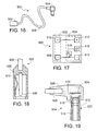
- FIG. 16 is a plan view of a dongle in accordance with a preferred embodiment of a present invention.
- FIG. 17 is a block diagram of the dongle illustrated in FIG. 16 .
- FIG. 18 is a side, partial section view of a dongle receptacle in accordance with one embodiment of a present invention.
- FIG. 19 is a side, partial section view of a dongle plug in accordance with one embodiment of a present invention.
- the present inventions are applicable to electronic devices such as palmtop computers, e-tablets, audio and video recording and playback devices, personal digital assistants, mobile telephones, digital cameras, electronic games, and any other electronic device that may be powered by an adapter.
- electronic devices such as palmtop computers, e-tablets, audio and video recording and playback devices, personal digital assistants, mobile telephones, digital cameras, electronic games, and any other electronic device that may be powered by an adapter.
- AC to DC adapters the present inventions are also applicable to DC to AC adapters, AC to AC adapters, and DC to DC adapters.
- a system in accordance with one embodiment of a present invention includes a notebook computer 100 and an AC to DC adapter 200 .
- the exemplary notebook computer 100 is, with respect to many of the structural and operating components, substantially similar to conventional portable computers such as the Hewlett-Packard Omnibook 6000 notebook PC. More specifically, the exemplary notebook computer 100 includes structural components such as a main housing 102 and display housing 104 that are pivotably coupled to one another by a hinge 106 .
- the top side of the main housing 102 (see FIG. 13 ) supports a user interface 108 including a keyboard, a touch pad, and right/left click buttons.
- the main housing 102 also includes a module bay for optional modules such as the illustrated CD-ROM drive module 110 (of FIG. 2 ), a 3.5 inch disk drive module, or a ZIP drive module.
- a bay for battery 112 is also provided.
- the display housing 104 also acts as a lid to cover the user interface 108 when in the closed position.
- a conventional latch arrangement (not shown) may be provided to lock the free end of the display housing 104 to the main housing 102 and maintain the display housing in the closed position.
- the operating components of the exemplary notebook computer 100 include a CPU (or “processor”) 116 , cache and RAM memory 118 , a power converter apparatus 120 , a hard disk drive 122 , a modem 124 , and a power receptacle 126 that is described in greater detail below.
- the exemplary computer 100 may also include other conventional components such as, for example, audio and video cards, headphone and microphone ports, serial, parallel and USB ports, keyboard and mouse ports, an operating system such as Microsoft® Windows, and various application programs such a word processing, spreadsheets, security programs and games.
- the exemplary adapter 200 includes a wall outlet plug 202 that may be connected to a wall outlet 204 , a power conversion apparatus 206 (e.g. a rectifier, inverter, filter and transformer arrangement) with an input and an output, a housing 208 ( FIG. 1 ) for the power conversion apparatus, and an adapter plug 210 that is configured to mate with the power receptacle 126 on the notebook computer 100 .
- a power conversion apparatus 206 e.g. a rectifier, inverter, filter and transformer arrangement
- a housing 208 FIG. 1
- an adapter plug 210 that is configured to mate with the power receptacle 126 on the notebook computer 100 .
- a suitable power conversion apparatus 206 for use with the exemplary computer 100 is the power conversion apparatus found in the Hewlett-Packard model No. F1781 AC to DC adapter.
- the exemplary notebook computer 100 (or other adapter powered electronic device) and adapter 200 are preferably configured such that the notebook computer is able to determine the power output rating of the adapter. As a result, the notebook computer 100 can, if necessary, alter its power consumption so that it does not attempt to draw more than the rated level of power. These functions are preferably performed at least in part by the CPU 116 , but may also be performed by dedicated processors and/or circuitry. Power consumption may be altered by, for example, altering the level of power being consumed by various power consuming apparatus within the notebook computer (or other electronic device). In the notebook computer context, power consumption may be altered by, for example, altering the CPU operation, battery charging function, hard disk operation and/or display operation.
- the exemplary notebook computer 100 determines the power output rating of the exemplary adapter 200 by measuring a value related to a circuit component (e.g. a resistor, inductor, capacitor or transformer) associated with the adapter, or one or more values related to a combination of circuit components associated with the adapter.
- a circuit component e.g. a resistor, inductor, capacitor or transformer
- the notebook computer 100 may be configured to measure one or more of the following circuit component values: resistance, inductance, capacitance, impedance or transformer coupling (sometimes referred to as the “turns ratio” of a transformer).
- the present inventions include any circuit component or circuit component combination and the measurement of the respective values associated therewith.
- the exemplary receptacle 126 and plug 210 each include three electrical contacts.
- the terms “plug” and “receptacle” are not being used to limit the inventions to any particular type of power connector physical structure and is instead being used to represent any type of power connector, regardless of physical structure.
- the notebook power receptacle 126 includes a positive contact 128 , a ground contact 130 and an adapter ID contact 132 , which are respectively connected to the appropriate circuitry within the notebook computer 100 by wires 134 , 136 , and 138 .
- the adapter plug 210 includes a positive contact 212 , a ground contact 214 , and an adapter ID contact 216 .
- the adapter plug 210 also includes an adapter ID resistor 218 .
- the positive contact 212 and ground contact 214 are respectively connected to the power conversion apparatus 206 ( FIG. 2 ) by wires 220 and 222 .
- the adapter ID contact 216 is connected to the adapter ID resistor 218 , and the ID resistor is in turn connected to the ground wire 222 in the manner illustrated in FIG. 3B .
- the adapter ID resistor 218 may be connected to the positive wire 220 in addition to the adapter ID contact 216 .
- the resistance of the adapter ID resistor 218 (“R ID ”) is used to represent the power rating of the adapter 200 .
- the exemplary notebook computer 100 (or other adapter powered device) measures the resistance R ID in order to determine power rating of the adapter 200 .
- the notebook computer 100 may, for example, store a table of resistance R ID values and the adapter power ratings to which the resistance R ID values correspond. Alternatively, an algorithm could be used to calculate adapter power ratings based on the measured resistance R ID value.
- a resistance R ID value of 10 k ⁇ corresponds to a 90-watt adapter
- a resistance R ID value of 20 k ⁇ corresponds to a 75-watt adapter
- a resistance R ID value of 30 k ⁇ could correspond to a 60-watt adapter.
- the table preferably assigns a power rating to a resistance R ID value of 0 k ⁇ in order to account for the situation where the exemplary notebook computer 100 is used in conjunction with an adapter having a conventional plug (i.e. a plug with a positive contact and a ground contact, but no ID resistor and ID contact).
- the ground contact 130 and adapter ID contact 132 of the computer power receptacle 126 are both in contact with the adapter's ground contact and, therefore, the measured resistance would be zero.
- a pre-selected “safe” adapter rating such as 60 watts, could be assigned to the resistance R ID value of 0 k ⁇ .
- the exemplary notebook computer 100 may also be configured to accommodate those instances where the notebook power receptacle 126 and adapter plug 210 are mechanically mismatched due to, for example, use of the notebook computer with an adapter (such as adapter 200 ) that was not intended for use with the computer.
- the adapter ID contact 132 may be slightly spaced from adapter ID contact 216 when the power receptacle 126 is connected to a mismatched adapter plug 210 . This could, for example, happen when the male portion of a power receptacle is shorter than the corresponding female portion of the adapter plug. The spacing results in the measured resistance R ID value being extremely high or infinite.
- the resistance R ID may be measured in any suitable manner. Although the present inventions are not so limited, one example of a circuit used by the notebook computer 100 to measure the resistance R ID is generally represented by reference numeral 140 in FIG. 5 .
- the notebook computer 100 is provided with an internal reference resistor 142 , having a resistance R REF , in series with the adapter contact 132 and, therefore, in series with the adapter ID resistor 218 .
- the notebook computer 100 applies a known voltage V APP (e.g. 5 V) across the ground and adapter contacts 130 and 132 and measures the voltage V REF across the reference resistor 142 .
- circuit components such as an inductor, capacitor or transformer
- adapter ID values such as inductance, capacitance, impedance or turns ratio would be measured.
- the receptacle 126 and plug 210 may be configured in any fashion that is suitable for their intended use. Exemplary configurations that may be employed in the notebook computer environment are illustrated FIGS. 6 and 7 with the wiring removed for purposes of clarity.
- a notebook power receptacle 126 includes a housing 144 and a post-like (or “male”) connector 146 that is mounted within the housing.
- One or more positive contacts 128 are positioned on the inner surface of the housing 144 , while the ground contact 130 and adapter ID contact 132 are carried by the connector 146 with insulation 148 therebetween.
- the positive contacts 128 are preferably, although not necessarily, spring-like contacts that deflect when the adapter plug 210 is connected to the notebook power receptacle 126 .
- the ground contact 130 is generally cylindrical and the adapter ID contact 132 includes a generally cylindrical portion and a generally semi-spherical portion.
- the positive contact 128 , ground contact 130 and adapter ID contact 132 are, as noted above, connected to the appropriate circuitry within the notebook computer 100 by wires (not shown in FIG. 6 ).
- a corresponding adapter plug 210 is provided with a generally hollow (or “female”) connector 224 that includes the positive contact 212 , ground contact 214 and adapter ID contact 216 .
- the positive contact 212 is generally cylindrical in shape and forms part of the outer surface of the connector 224
- the ground contact 214 is generally cylindrical in shape and forms part of the inner surface of the connector
- the adapter ID contact 216 which has a generally semi-spherical portion and a generally cylindrical portion, forms part of the inner surface of the connector.
- Such contacts are mechanically configured to mate with the corresponding contacts on the power receptacle 126 .
- the contacts 212 , 214 , and 216 which are separated by insulating material 226 , are individually connected to a circuit board 228 which carries the adapter ID resistor 218 .
- the circuit board 228 also connects the ground contact 214 , sensing contact 216 and adapter ID resistor 218 to one another in the manner illustrated in FIG. 3B .
- the positive and ground wires 220 and 222 extend from the circuit board 228 to the power conversion apparatus 206 by way of a cord 230 .
- An overmold 232 holds the various elements together in the exemplary embodiment illustrated in FIG. 7 and also provides a gripping surface for the user.
- the connector 224 , cord 230 and overmold 232 are respectively arranged such that the cord and connector are at a right angle to one another. Nevertheless, the present inventions are not limited to any particular connector, cord and overmold arrangement. The arrangement may vary to suit particular needs. As illustrated for example in FIG. 11 (which is discussed in greater detail below), the connector, cord and overmold may also be configured in “in-line” fashion.
- the contacts in the exemplary embodiments described above and below are preferably formed from highly conductive materials such as gold, silver and brass with a nickel coating.
- the housings and overmolds are preferably formed from polyvinylchloride (“PVC”), while the insulation is preferably formed from polybutylene terephthalate (“PBT”).
- FIGS. 8 and 9 Another exemplary receptacle and plug combination is illustrated in FIGS. 8 and 9 .
- the receptacle and plug illustrated in FIGS. 8 and 9 are functionally similar to the receptacle and plug illustrated in FIGS. 6 and 7 and elements with similar functions are identified by similar reference numerals.
- the exemplary notebook power receptacle 126 ′ illustrated in FIG. 8 includes a housing 144 ′ and a post-like connector 146 ′, mounted within the housing, that carries a positive contact 128 ′ on its outer surface. In inner surface of the housing 144 ′ includes a ground contact 130 ′ and one or more adapter ID contacts 132 ′.
- the adapter ID contacts 132 ′ are preferably, although not necessarily, spring-like contacts that deflect when the adapter plug 210 ′ ( FIG. 9 ) is connected to the notebook power receptacle 126 ′, while the ground contact 130 ′ is generally cylindrical.
- the positive contact 128 ′, ground contact 130 ′ and adapter ID contact 132 ′ are, as noted above, connected to the appropriate circuitry within the notebook computer 100 by wires (not shown in FIG. 8 ).
- the exemplary corresponding adapter plug 210 ′ illustrated in FIG. 9 is provided with a generally hollow connector 224 ′ that includes a positive contact 212 ′, a ground contact 214 ′ and an adapter ID contact 216 ′.
- the positive contact 212 ′ is generally obround in shape (i.e. it has a cylindrical portion and a semi-spherical portion) and forms part of the inner surface of the connector 224 ′
- the ground contact 214 ′ is generally cylindrical in shape and forms part of the outer surface of the connector
- the adapter ID contact 216 ′ is generally cylindrical in shape and also forms part of the outer surface of the connector.
- the size and shape of the positive contact 212 ′ corresponds to that of the positive contact 128 ′ on the notebook power receptacle 126 ′.
- the size and space between the ground contacts 214 ′ and adapter ID contact 216 ′ correspond to that of the ground and adapter ID contacts 130 ′ and 132 ′ on the notebook power receptacle 126 ′.
- the contacts 212 ′, 214 ′, and 216 ′, which are separated by insulating material 226 are connected by individual wires to the circuit board 228 (and adapter ID resistor 218 ) and the circuit board is connected to the adapter power conversion apparatus 206 in the manner described above.
- FIGS. 10 and 11 Another exemplary receptacle and plug combination is illustrated in FIGS. 10 and 11 .
- the receptacle and plug illustrated in FIGS. 10 and 11 are functionally similar to the receptacle and plug illustrated in FIGS. 6 and 7 and elements with similar function are identified by similar reference numerals.
- the exemplary notebook power receptacle 126 ′′ illustrated in FIG. 10 is provided with housing 144 ′′ with a central opening 150 and a cylindrical slot 152 .
- the inner surface of the central opening 150 includes one or more positive contacts 128 ′′, a ground contact 130 ′′ and one or more adapter ID contacts 132 ′′.
- the ground and adapter ID contacts 128 ′′ and 132 ′′ are preferably, although not necessarily, spring-like contacts that deflect when the adapter plug 210 ′′ ( FIG. 11 ) is connected to the notebook power receptacle 126 ′′, while the ground contact 130 ′′ is generally cylindrical.
- the positive contact 128 ′′, ground contact 130 ′′ and adapter ID contact 132 ′′ are, as noted above, connected to the appropriate circuitry within the notebook computer 100 by wires (not shown in FIG. 10 ).
- the exemplary corresponding adapter plug 210 ′′ illustrated in FIG. 11 is provided with a generally post-like connector 224 ′′ that includes a positive contact 212 ′′, a ground contact 214 ′′ and an adapter ID contact 216 ′′.
- the contacts 212 ′′, 214 ′′, and 216 ′′ are all generally cylindrical in shape and all form part of the outer surface of the connector 224 ′′.
- the contacts 212 ′′, 214 ′′, and 216 ′′, which are linearly arranged and separated by insulating material 226 are connected by individual wires (not shown) to the circuit board 228 (and adapter ID resistor 218 ) and the circuit board is connected to the adapter power conversion apparatus 206 in the manner described above.
- the size and space between the contacts 212 ′′, 214 ′′ and 216 ′′ corresponds to that of the contacts 128 ′′, 130 ′′ and 132 ′′ on the notebook power receptacle 126 ′′.
- An overmold 232 ′′ is configured such that the cord 230 is substantially coaxial with the plugging axis.
- an adapter having a plug with three contacts i.e. a positive contact, ground contact and adapter ID contact
- an electronic device such as a notebook computer
- a conversion device may be provided in order to facilitate the connection of a three-contact adapter plug to a two-contact electronic device power receptacle.
- One example of a conversion device in accordance with a present invention is generally represented by reference numeral 300 in FIG. 12 .
- conversion devices may be configured for use with any three-contact adapter plug, including the adapter plugs illustrated in FIGS. 7 and 9
- the exemplary conversion device 300 is configured to mate with the adapter plug 210 ′′, which is described above with reference to FIG. 11 .
- the conversion device 300 includes a molded housing 302 with a central opening 304 , which is configured to receive the connector 224 ′′ of the adapter plug 210 ′′, and a cylindrical slot 306 , which is configured to receive the cover 234 .
- Adapter-side positive and ground contacts 308 and 310 which together form part of an adapter-side receptacle 311 , are positioned within the central opening 304 such that they mate with the positive and ground contacts 212 ′′ and 214 ′′ on the connector 224 ′′.
- the positive contact 308 is preferably in the form of one or more spring-like contacts.
- the exemplary conversion device 300 does not, however, include a contact which corresponds to the adapter ID contact 216 ′′ on the plug 210 ′′.
- the positive and ground contacts 308 and 310 are electrically connected by, for example, suitable wires (not shown) to electronic device-side positive and ground contacts 312 and 314 .
- the electronic device-side positive and ground contacts 312 and 314 together form part of an electronic device side plug 315 .
- the electronic device-side positive and ground contacts 312 and 314 of the exemplary conversion device 300 would be connected to the positive and ground contacts of an electronic device power receptacle, while the adapter plug 210 ′′ positive and ground contacts 212 ′′ and 214 ′′ would be connected to the adapter-side positive and ground contacts 308 and 310 .
- the conversion device 300 may be composed of a separate adapter-side receptacle and an electronic device-side plug that are connected to one another by a suitable cord.
- the present inventions also include power dongles that may be used when an adapter is powering a pair of electronic devices. Although not limited to use with such devices, one exemplary implementation of such a power dongle is described below in the context of a peripheral electronic device that may be used in conjunction with the exemplary notebook computer 100 and adapter 200 in the manner illustrated in FIGS. 13–15 .
- the peripheral device power dongle is configured such that the exemplary notebook computer 100 is able to determine the power requirements of the peripheral device in addition to the power rating of the adapter 200 . As a result, the notebook computer 100 can, if necessary, alter its power consumption so that so that the computer and peripheral device does not together attempt to draw more than the adapter's rated level of power.
- a digital camera is one example of a peripheral electronic device in accordance with the present inventions.
- Other exemplary peripheral electronic devices include printers, docking trays, CDRW drives and joy sticks.
- the exemplary digital camera 400 includes a housing 402 , a lens 404 and power consuming apparatus 406 (e.g. image processing circuitry).
- the exemplary digital camera 400 also includes a peripheral device power dongle 408 .
- peripheral device power dongles in accordance with the present inventions may be configured for use with any adapter and electronic device
- the exemplary dongle 408 is configured for use with the notebook computer 100 and adapter 200 .
- the exemplary dongle 408 is configured to mate with the electronic device receptacle 126 ′ and adapter plug 210 ′ illustrated in FIGS. 8 and 9 . More specifically, the dongle 408 includes a pair of positive contacts 410 a / 410 b and a pair of ground contacts 412 a / 412 b which are connected positive-to-positive and ground-to-ground, as well as to the power consuming apparatus 406 , in the manner illustrated in FIG. 14 .
- the positive contacts 410 a / 410 b and ground contacts 412 a / 412 b on the dongle 408 are positioned such that they mate with the corresponding positive contacts 128 ′/ 212 ′ and ground contacts 130 ′/ 214 ′ on the power receptacle 126 ′ and adapter plug 210 ′. So arranged, the adapter 200 provides power to both the notebook computer 100 and the digital camera 400 .
- the exemplary peripheral device power dongle 408 also includes a peripheral ID resistor 414 , which has a resistance R PID that is representative of the peripheral device power requirements, and a pair of ID contacts 416 a / 416 b .
- R PID resistance
- ID contacts 416 a / 416 b on the dongle 408 are positioned such that they mate with the corresponding ID contacts 132 ′/ 216 ′ on the power receptacle 126 ′ and adapter plug 210 ′ respectively. So arranged, the peripheral ID resistor 414 is in series with the adapter ID resistor 218 ′ when the plug 210 ′ and dongle 408 are connected to one another.
- the notebook computer 100 (or other electronic device) reads the combined resistance R ID +R PID and respond by, if necessary, drawing less power than it would have absent the presence of the peripheral device.
- the peripheral device power dongle 408 may be configured in any fashion that is suitable for its intended use.
- One exemplary configuration which may be employed in combination with the exemplary notebook computer power receptacle 126 ′ and adapter plug 210 ′ illustrated FIGS. 8 and 9 , is illustrated in FIG. 15 .
- the positive contact 410 a , ground contact 412 a and ID contact 416 a are positioned within an opening 418 in an overmold 420 , thereby forming an adapter-side power receptacle 422 that mates with the adapter plug 210 ′.
- the positive contact 410 b , ground contact 412 b and ID contact 416 b are mounted on a connector 424 , thereby forming a device-side power plug 426 that mates with the electronic device receptacle 126 ′.
- the peripheral ID resistor 414 is mounted on a circuit board 428 .
- the positive contacts 410 a / 410 b , ground contacts 412 a / 412 b , peripheral ID resistor 414 and ID contacts 416 a / 416 b are connected in the manner illustrated in FIG. 14 by the circuit board 428 and wiring (not shown in FIG. 15 ). Positive and ground wires (not shown in FIG. 15 ) extend from the circuit board 428 to the power consuming apparatus 406 (not shown) by way of a cord 430 .
- the present inventions also include power dongles that may be used when a conventional two-contact adapter without an ID resistor and contact arrangement is powering an electronic device (such as the exemplary notebook computer 100 ) that is configured to measure a resistance that is indicative of adapter power rating.
- a power dongle includes a two-contact power receptacle that may be connected to the adapter and a three-contact power plug, which is provided with an ID resistor, that may be connected to the electronic device.
- One example of this type of dongle is generally represented by reference numeral 500 in FIGS. 16 and 17 .
- the exemplary dongle 500 includes an adapter-side power receptacle 502 , a device-side power plug 504 , and a cord 506 that connects the two.
- the exemplary adapter-side power receptacle 502 includes a positive contact 508 and a ground contact 510 , which are configured to mate with the corresponding positive and ground contacts on a conventional adapter plug.
- the exemplary device-side power plug 504 includes a positive contact 512 , a ground contact 514 and an adapter ID contact 516 , which are configured to mate with the corresponding positive, ground and adapter ID contacts the an electronic device power receptacle.
- a dongle ID resistor 518 is also provided. [As noted above, other circuit components or combinations thereof may be employed in place of resistors.]
- the plugs 502 and 504 are connected to one another positive-to-positive and ground-to-ground.
- the electronic device measures the resistance of the dongle ID resistor 518 (“R DID ”) and respond, in the manner described above, just as if it had measured the resistance of a resistor associated with an adapter.
- the resistance of the dongle ID resistor 518 may be displayed on the dongle so that the dongle may be readily paired with an appropriate adapter by the user.
- the resistance of the dongle ID resistor 518 may be chosen such that it corresponds to a “safe” adapter power rating in order to insure that the demands of the electronic device do not exceed the rating of the adapter selected by the user.
- a resistance R DID value that corresponds to a 60 watt adapter (30 k ⁇ using the exemplary values described above) would be appropriate because most of the notebook adapters that are currently in service are at least 60 watts.
- the dongle receptacle 502 and plug 504 may be configured in any fashion that is suitable for their intended use. Exemplary configurations, which may be employed in combination with a conventional adapter and the exemplary notebook computer power receptacle 126 illustrated FIG. 6 , are illustrated in FIGS. 18 and 19 .
- the positive and ground contacts 508 and 510 in the exemplary adapter-side power receptacle 502 are mounted within an overmold 520 .
- the positive contact 508 is a post-like (or “male”) connector and the ground contact 510 is preferably, although not necessarily, a spring-like contact that deflects when the adapter-side power receptacle 502 is connected to an adapter plug.
- the exemplary device-side power plug 504 illustrated in FIG. 19 is essentially identical to the adapter plug 210 illustrated in FIG. 7 .
- the positive contact 512 , ground contact 514 and adapter ID contact 516 are mounted on a connector 522
- the dongle ID resistor 518 is carried by a circuit board 524
- the elements are held together by an overmold 526 .
- the exemplary power dongle 500 includes a receptacle and a plug that are connected to one another by a cord
- power dongles in accordance with the present invention may be configured as unitary structures similar to that illustrated in FIG. 12 .
- the adapter ID resistors (or other circuit components), peripheral device ID resistors (or other circuit components), and/or dongle ID resistors (or other circuit components) described above can be located in areas other than a plug.
- the adapter ID resistors (or other circuit components) could be located within the housing and connected to the appropriate contacts by wires that extend therefrom.
- the receptacle and plug on any conversion devices or dongle may both be male, may both be female, or may be one male/one female, as may be required for particular applications.
Abstract
Description
Claims (66)
Priority Applications (1)
| Application Number | Priority Date | Filing Date | Title |
|---|---|---|---|
| US10/202,136 US7028202B2 (en) | 2002-07-24 | 2002-07-24 | Power adapter identification |
Applications Claiming Priority (1)
| Application Number | Priority Date | Filing Date | Title |
|---|---|---|---|
| US10/202,136 US7028202B2 (en) | 2002-07-24 | 2002-07-24 | Power adapter identification |
Publications (2)
| Publication Number | Publication Date |
|---|---|
| US20040018774A1 US20040018774A1 (en) | 2004-01-29 |
| US7028202B2 true US7028202B2 (en) | 2006-04-11 |
Family
ID=30769759
Family Applications (1)
| Application Number | Title | Priority Date | Filing Date |
|---|---|---|---|
| US10/202,136 Active 2024-05-04 US7028202B2 (en) | 2002-07-24 | 2002-07-24 | Power adapter identification |
Country Status (1)
| Country | Link |
|---|---|
| US (1) | US7028202B2 (en) |
Cited By (39)
| Publication number | Priority date | Publication date | Assignee | Title |
|---|---|---|---|---|
| US20060014565A1 (en) * | 2004-07-19 | 2006-01-19 | Chien-Tsung Chen | Multi-output connector capable of receiving data wirelessly |
| US20060020833A1 (en) * | 2004-07-22 | 2006-01-26 | Dell Products L.P. | Information handling system with power fault protection circuit |
| US20060089533A1 (en) * | 2003-04-14 | 2006-04-27 | Softscope Medical Technologies, Inc. | Self-propellable endoscopic apparatus and method |
| US20070188984A1 (en) * | 2005-11-01 | 2007-08-16 | Opsitos Robert J Jr | Remote id resistor assembly for wiring harness |
| US20070285239A1 (en) * | 2006-06-12 | 2007-12-13 | Easton Martyn N | Centralized optical-fiber-based RFID systems and methods |
| US20080100467A1 (en) * | 2006-10-31 | 2008-05-01 | Downie John D | Radio frequency identification of component connections |
| US20080218355A1 (en) * | 2007-03-09 | 2008-09-11 | Downie John D | Optically addressed RFID elements |
| US20080309310A1 (en) * | 2007-06-14 | 2008-12-18 | Illinois Tool Works Inc. | High voltage power supply connector system |
| US20090177900A1 (en) * | 2005-02-01 | 2009-07-09 | Sawyers Thomas P | Systems and Methods for Controlling Use of Power in a Computer System |
| US20100178058A1 (en) * | 2006-12-14 | 2010-07-15 | Kozischek David R | Rfid systems and methods for optical fiber network deployment and maintenance |
| US7772975B2 (en) | 2006-10-31 | 2010-08-10 | Corning Cable Systems, Llc | System for mapping connections using RFID function |
| DE112008003629T5 (en) | 2008-01-22 | 2010-11-04 | Hewlett-Packard Development Company, L.P., Houston | Delay circuit with reset feature |
| US20110081807A1 (en) * | 2009-10-06 | 2011-04-07 | Mellanox Technologies Ltd. | Adapter for pluggable module |
| US8004267B2 (en) * | 2007-08-21 | 2011-08-23 | Ford Global Technologies, Llc | Power converter system for an automotive vehicle and method for configuring same |
| US20110234797A1 (en) * | 2010-03-23 | 2011-09-29 | Lufthansa Technik Ag | Camera unit in particular for surveillance in a transportation means |
| US8212386B2 (en) | 2006-04-28 | 2012-07-03 | ACCO Brands Corporation | Power supply system |
| US8248208B2 (en) | 2008-07-15 | 2012-08-21 | Corning Cable Systems, Llc. | RFID-based active labeling system for telecommunication systems |
| US8264355B2 (en) | 2006-12-14 | 2012-09-11 | Corning Cable Systems Llc | RFID systems and methods for optical fiber network deployment and maintenance |
| US8330303B2 (en) | 2004-01-15 | 2012-12-11 | Comarco Wireless Technologies, Inc. | Power supply equipment utilizing interchangeable tips to provide a data signal and power from an adapter to various electronic devices |
| US20120329332A1 (en) * | 2011-06-21 | 2012-12-27 | Lai Yen-Chang | Plug assembly adapted to an adapter and a computer device |
| US8419444B2 (en) | 2010-09-16 | 2013-04-16 | Mellanox Technologies Ltd. | Adapter for high-speed ethernet |
| US20130196549A1 (en) * | 2012-02-01 | 2013-08-01 | Rad Data Communications Ltd. | Sfp functionality extender |
| US8731405B2 (en) | 2008-08-28 | 2014-05-20 | Corning Cable Systems Llc | RFID-based systems and methods for collecting telecommunications network information |
| TWI463741B (en) * | 2009-10-15 | 2014-12-01 | Compal Electronics Inc | Power receptacle for portable electronic device |
| US8923525B2 (en) | 2013-02-06 | 2014-12-30 | Zeikos Inc. | Power transferring headphones |
| WO2015030815A1 (en) * | 2013-08-30 | 2015-03-05 | Hewlett-Packard Development Company, L.P. | Identification of a unique attribute of a power adapter based on an adjust pin |
| US9118240B2 (en) | 2011-08-31 | 2015-08-25 | Comarco Wireless Technologies, Inc. | Power supply equipment providing multiple identification signals |
| US9153960B2 (en) | 2004-01-15 | 2015-10-06 | Comarco Wireless Technologies, Inc. | Power supply equipment utilizing interchangeable tips to provide power and a data signal to electronic devices |
| US9271063B2 (en) | 2013-02-06 | 2016-02-23 | Zeikos Inc. | Power transferring headphones |
| US9276539B2 (en) | 2013-02-06 | 2016-03-01 | Zeikos Inc. | Power transferring headphones |
| US9563832B2 (en) | 2012-10-08 | 2017-02-07 | Corning Incorporated | Excess radio-frequency (RF) power storage and power sharing RF identification (RFID) tags, and related connection systems and methods |
| USD813873S1 (en) | 2017-02-21 | 2018-03-27 | Verily Life Sciences Llc | Electronic connector for charging or data transfer |
| US9935408B1 (en) | 2017-06-16 | 2018-04-03 | Verily Life Sciences Llc | Electronic connector for charging or data transfer |
| US10128627B1 (en) | 2017-06-28 | 2018-11-13 | Mellanox Technologies, Ltd. | Cable adapter |
| US10444453B1 (en) | 2018-07-25 | 2019-10-15 | Mellanox Technologies, Ltd. | QSFP-DD to SFP-DD adapter |
| US10644472B2 (en) | 2017-06-28 | 2020-05-05 | Mellanox Technologies, Ltd. | Cable adapter |
| US10705309B2 (en) | 2018-06-06 | 2020-07-07 | Mellanox Technologies, Ltd. | RF EMI reducing fiber cable assembly |
| US10741954B1 (en) | 2019-03-17 | 2020-08-11 | Mellanox Technologies, Ltd. | Multi-form-factor connector |
| US11169330B2 (en) | 2019-10-24 | 2021-11-09 | Mellanox Technologies Tlv Ltd. | Wavelength-splitting optical cable |
Families Citing this family (34)
| Publication number | Priority date | Publication date | Assignee | Title |
|---|---|---|---|---|
| US20100124634A1 (en) * | 1996-09-26 | 2010-05-20 | Slotta Mark R | Cushioned cap with annular portion and method for forming same |
| KR100520075B1 (en) * | 2003-06-23 | 2005-10-11 | 삼성전자주식회사 | Ac/dc adapter and notebook computer for using the same |
| US20040266425A1 (en) * | 2003-06-24 | 2004-12-30 | Sbc, Inc. | Wireless wide area network charger and cradle |
| US7616950B2 (en) * | 2003-09-04 | 2009-11-10 | At&T Intellectual Property I, L.P. | Call forwarding control device and method of call management |
| US8526977B2 (en) * | 2003-09-23 | 2013-09-03 | At&T Intellectual Property I, L.P. | Location based call routing for call answering services |
| US7769392B2 (en) * | 2003-09-23 | 2010-08-03 | At&T Intellectual Property I, L.P. | Method and system for forwarding wireless communications |
| US20050064853A1 (en) * | 2003-09-23 | 2005-03-24 | Sbc Knowledge Ventures, L.P. | Unified telephone handset for personal communications based on wireline and wireless network convergence |
| US7577427B2 (en) * | 2003-11-05 | 2009-08-18 | At&T Intellectual Property I, L.P. | System and method of transitioning between cellular and voice over internet protocol communication |
| US6976885B2 (en) * | 2004-03-02 | 2005-12-20 | Mobility Electronics, Inc. | Keyed universal power tip and power source connectors |
| WO2005120160A2 (en) * | 2004-06-10 | 2005-12-22 | Sendyne Corporation | External versatile battery with power saving mode |
| US20050277431A1 (en) * | 2004-06-14 | 2005-12-15 | Sbc Knowledge Ventures, Lp | System and method for managing wireless data communications |
| US20060003806A1 (en) * | 2004-07-02 | 2006-01-05 | Sbc Knowledge Ventures, L.P. | Phone synchronization device and method of handling personal information |
| US7580837B2 (en) | 2004-08-12 | 2009-08-25 | At&T Intellectual Property I, L.P. | System and method for targeted tuning module of a speech recognition system |
| US7581130B2 (en) * | 2004-11-12 | 2009-08-25 | Hewlett-Packard Development Company, L.P. | Power management system and method |
| US7242751B2 (en) | 2004-12-06 | 2007-07-10 | Sbc Knowledge Ventures, L.P. | System and method for speech recognition-enabled automatic call routing |
| US7751551B2 (en) | 2005-01-10 | 2010-07-06 | At&T Intellectual Property I, L.P. | System and method for speech-enabled call routing |
| US7657020B2 (en) | 2005-06-03 | 2010-02-02 | At&T Intellectual Property I, Lp | Call routing system and method of using the same |
| US8005204B2 (en) * | 2005-06-03 | 2011-08-23 | At&T Intellectual Property I, L.P. | Call routing system and method of using the same |
| CN2809966Y (en) * | 2005-06-21 | 2006-08-23 | 富士康(昆山)电脑接插件有限公司 | Power supply connector |
| US7536569B2 (en) * | 2006-04-24 | 2009-05-19 | Dell Products L.P. | System and method for managing power provided to a portable information handling system |
| US20100134995A1 (en) * | 2008-12-02 | 2010-06-03 | Raytheon Company | Electrical Interconnection System |
| US7854617B2 (en) * | 2008-12-12 | 2010-12-21 | Dell Products, L.P. | Grounded power adapter |
| US8504816B2 (en) * | 2010-01-12 | 2013-08-06 | Atmel Rousset S.A.S. | Integrated circuit device configuration |
| US8645720B2 (en) * | 2010-01-20 | 2014-02-04 | Dell Products L.P. | Power adaptor detection system |
| TWI403889B (en) * | 2011-01-20 | 2013-08-01 | Acer Inc | Protable electronic device and method for adjusting system performance thereof |
| JP2013026768A (en) * | 2011-07-20 | 2013-02-04 | Molex Inc | Connector for earphone |
| JP5977701B2 (en) * | 2013-03-28 | 2016-08-24 | 日本電信電話株式会社 | AC adapter degradation status judgment system for information communication terminal device |
| USD776058S1 (en) | 2014-04-17 | 2017-01-10 | Google Inc. | Electrical connector |
| US9419376B1 (en) * | 2014-04-17 | 2016-08-16 | Google Inc. | Multipurpose, electronically versatile connector for wearable electronics |
| EP3289684A4 (en) * | 2015-04-29 | 2018-12-19 | Hewlett-Packard Development Company, L.P. | Connector element information detections |
| GB2547672B (en) | 2016-02-25 | 2018-02-21 | Rejuvetech Ltd | System and method |
| US10659852B2 (en) | 2017-07-20 | 2020-05-19 | Hewlett-Packard Development Company, L.P. | Connector element information detections |
| CN109037996A (en) * | 2018-07-26 | 2018-12-18 | 努比亚技术有限公司 | A kind of adapter |
| TWI795115B (en) * | 2021-12-09 | 2023-03-01 | 英屬安吉拉商聚優佤有限公司 | Anti-theft device for automobile charging adapter and automobile charging adapter |
Citations (7)
| Publication number | Priority date | Publication date | Assignee | Title |
|---|---|---|---|---|
| US5297015A (en) | 1989-07-21 | 1994-03-22 | Hitachi, Ltd. | Power supply control system |
| US5384544A (en) | 1993-03-02 | 1995-01-24 | Hewlett-Packard Corporation | Method and apparatus for calibrating the energy output of a defibrillator |
| US5570002A (en) * | 1994-02-18 | 1996-10-29 | Ergo Mechanical Systems, Incorporated | Universal power-supply connection system for multiple electronic devices |
| US5593323A (en) * | 1995-01-13 | 1997-01-14 | Operating Technical Electronics, Inc. | Reversible polarity accessory cable |
| US6368155B1 (en) * | 1999-07-16 | 2002-04-09 | Molex Incorporated | Intelligent sensing connectors |
| US6498957B1 (en) * | 1998-11-04 | 2002-12-24 | Nec Corporation | Power supply control in portable data terminal |
| US20030159073A1 (en) * | 2002-02-15 | 2003-08-21 | Breen John J. | Battery charger current limiting based on AC power adapter power |
-
2002
- 2002-07-24 US US10/202,136 patent/US7028202B2/en active Active
Patent Citations (7)
| Publication number | Priority date | Publication date | Assignee | Title |
|---|---|---|---|---|
| US5297015A (en) | 1989-07-21 | 1994-03-22 | Hitachi, Ltd. | Power supply control system |
| US5384544A (en) | 1993-03-02 | 1995-01-24 | Hewlett-Packard Corporation | Method and apparatus for calibrating the energy output of a defibrillator |
| US5570002A (en) * | 1994-02-18 | 1996-10-29 | Ergo Mechanical Systems, Incorporated | Universal power-supply connection system for multiple electronic devices |
| US5593323A (en) * | 1995-01-13 | 1997-01-14 | Operating Technical Electronics, Inc. | Reversible polarity accessory cable |
| US6498957B1 (en) * | 1998-11-04 | 2002-12-24 | Nec Corporation | Power supply control in portable data terminal |
| US6368155B1 (en) * | 1999-07-16 | 2002-04-09 | Molex Incorporated | Intelligent sensing connectors |
| US20030159073A1 (en) * | 2002-02-15 | 2003-08-21 | Breen John J. | Battery charger current limiting based on AC power adapter power |
Cited By (65)
| Publication number | Priority date | Publication date | Assignee | Title |
|---|---|---|---|---|
| US20060089533A1 (en) * | 2003-04-14 | 2006-04-27 | Softscope Medical Technologies, Inc. | Self-propellable endoscopic apparatus and method |
| US10855086B2 (en) | 2004-01-15 | 2020-12-01 | Comarco Wireless Systems Llc | Power supply equipment utilizing interchangeable tips to provide power and a data signal to electronic devices |
| US9601922B2 (en) | 2004-01-15 | 2017-03-21 | Comarco Wireless Technologies, Inc. | Power supply equipment utilizing interchangeable tips to provide power and a data signal to electronic devices |
| US10855087B1 (en) | 2004-01-15 | 2020-12-01 | Comarco Wireless Systems Llc | Power supply systems |
| US9413187B2 (en) | 2004-01-15 | 2016-08-09 | Comarco Wireless Technologies, Inc. | Power supply system providing power and analog data signal for use by portable electronic device to control battery charging |
| US8330303B2 (en) | 2004-01-15 | 2012-12-11 | Comarco Wireless Technologies, Inc. | Power supply equipment utilizing interchangeable tips to provide a data signal and power from an adapter to various electronic devices |
| US9647477B2 (en) | 2004-01-15 | 2017-05-09 | Comarco Wireless Technologies, Inc. | Power supply equipment utilizing interchangeable tips to provide power and a data signal to electronic devices |
| US9806548B2 (en) | 2004-01-15 | 2017-10-31 | Comarco Wireless Technologies, Inc. | Power supply system providing power and analog data signal for use by portable electronic device to control battery charging |
| US11586233B2 (en) | 2004-01-15 | 2023-02-21 | Comarco Wireless Systems Llc | Power supply systems |
| US8492933B2 (en) | 2004-01-15 | 2013-07-23 | Comarco Wireless Technologies, Inc. | Power supply equipment providing a data signal, identification information and power to an electronic device |
| US10951042B2 (en) | 2004-01-15 | 2021-03-16 | Comarco Wireless Systems Llc | Power supply systems |
| US9153960B2 (en) | 2004-01-15 | 2015-10-06 | Comarco Wireless Technologies, Inc. | Power supply equipment utilizing interchangeable tips to provide power and a data signal to electronic devices |
| US20060014565A1 (en) * | 2004-07-19 | 2006-01-19 | Chien-Tsung Chen | Multi-output connector capable of receiving data wirelessly |
| US20060020833A1 (en) * | 2004-07-22 | 2006-01-26 | Dell Products L.P. | Information handling system with power fault protection circuit |
| US7363518B2 (en) * | 2004-07-22 | 2008-04-22 | Dell Products L.P. | Information handling system with power fault protection circuit |
| US8276006B2 (en) | 2005-02-01 | 2012-09-25 | Hewlett-Packard Development Company, L.P. | System and method for controlling use of power in a computer system |
| US8103885B2 (en) | 2005-02-01 | 2012-01-24 | Hewlett-Packard Development Company, L.P. | Systems and methods for controlling use of power in a computer system |
| US20100235659A1 (en) * | 2005-02-01 | 2010-09-16 | Sawyers Thomas P | System and method for controlling use of power in a computer system |
| US20090177900A1 (en) * | 2005-02-01 | 2009-07-09 | Sawyers Thomas P | Systems and Methods for Controlling Use of Power in a Computer System |
| US7710743B2 (en) * | 2005-11-01 | 2010-05-04 | Black & Decker Inc. | Remote ID resistor assembly for wiring harness |
| US20070188984A1 (en) * | 2005-11-01 | 2007-08-16 | Opsitos Robert J Jr | Remote id resistor assembly for wiring harness |
| US8212386B2 (en) | 2006-04-28 | 2012-07-03 | ACCO Brands Corporation | Power supply system |
| US20070285239A1 (en) * | 2006-06-12 | 2007-12-13 | Easton Martyn N | Centralized optical-fiber-based RFID systems and methods |
| US7782202B2 (en) | 2006-10-31 | 2010-08-24 | Corning Cable Systems, Llc | Radio frequency identification of component connections |
| US20080100467A1 (en) * | 2006-10-31 | 2008-05-01 | Downie John D | Radio frequency identification of component connections |
| US7772975B2 (en) | 2006-10-31 | 2010-08-10 | Corning Cable Systems, Llc | System for mapping connections using RFID function |
| US7760094B1 (en) | 2006-12-14 | 2010-07-20 | Corning Cable Systems Llc | RFID systems and methods for optical fiber network deployment and maintenance |
| US20100178058A1 (en) * | 2006-12-14 | 2010-07-15 | Kozischek David R | Rfid systems and methods for optical fiber network deployment and maintenance |
| US8264355B2 (en) | 2006-12-14 | 2012-09-11 | Corning Cable Systems Llc | RFID systems and methods for optical fiber network deployment and maintenance |
| US20080218355A1 (en) * | 2007-03-09 | 2008-09-11 | Downie John D | Optically addressed RFID elements |
| US7547150B2 (en) | 2007-03-09 | 2009-06-16 | Corning Cable Systems, Llc | Optically addressed RFID elements |
| US20080309310A1 (en) * | 2007-06-14 | 2008-12-18 | Illinois Tool Works Inc. | High voltage power supply connector system |
| US7828586B2 (en) * | 2007-06-14 | 2010-11-09 | Illinois Tool Works Inc. | High voltage power supply connector system |
| CN101373928B (en) * | 2007-08-21 | 2014-05-28 | 福特全球技术公司 | Power supply converter system for vehicle |
| US8004267B2 (en) * | 2007-08-21 | 2011-08-23 | Ford Global Technologies, Llc | Power converter system for an automotive vehicle and method for configuring same |
| DE112008003629T5 (en) | 2008-01-22 | 2010-11-04 | Hewlett-Packard Development Company, L.P., Houston | Delay circuit with reset feature |
| US8248208B2 (en) | 2008-07-15 | 2012-08-21 | Corning Cable Systems, Llc. | RFID-based active labeling system for telecommunication systems |
| US8731405B2 (en) | 2008-08-28 | 2014-05-20 | Corning Cable Systems Llc | RFID-based systems and methods for collecting telecommunications network information |
| US9058529B2 (en) | 2008-08-28 | 2015-06-16 | Corning Optical Communications LLC | RFID-based systems and methods for collecting telecommunications network information |
| US7934959B2 (en) * | 2009-10-06 | 2011-05-03 | Mellanox Technologies Ltd. | Adapter for pluggable module |
| US20110081807A1 (en) * | 2009-10-06 | 2011-04-07 | Mellanox Technologies Ltd. | Adapter for pluggable module |
| TWI463741B (en) * | 2009-10-15 | 2014-12-01 | Compal Electronics Inc | Power receptacle for portable electronic device |
| US9030557B2 (en) * | 2010-03-23 | 2015-05-12 | Lufthansa Technik Ag | Camera unit in particular for surveillance in a transportation means |
| US20110234797A1 (en) * | 2010-03-23 | 2011-09-29 | Lufthansa Technik Ag | Camera unit in particular for surveillance in a transportation means |
| US8419444B2 (en) | 2010-09-16 | 2013-04-16 | Mellanox Technologies Ltd. | Adapter for high-speed ethernet |
| US8499183B2 (en) * | 2011-06-21 | 2013-07-30 | Wistron Corporation | Plug assembly adapted to an adapter and a computer device |
| US20120329332A1 (en) * | 2011-06-21 | 2012-12-27 | Lai Yen-Chang | Plug assembly adapted to an adapter and a computer device |
| US9118240B2 (en) | 2011-08-31 | 2015-08-25 | Comarco Wireless Technologies, Inc. | Power supply equipment providing multiple identification signals |
| US20130196549A1 (en) * | 2012-02-01 | 2013-08-01 | Rad Data Communications Ltd. | Sfp functionality extender |
| US8851929B2 (en) * | 2012-02-01 | 2014-10-07 | Rad Data Communications Ltd. | SFP functionality extender |
| US9563832B2 (en) | 2012-10-08 | 2017-02-07 | Corning Incorporated | Excess radio-frequency (RF) power storage and power sharing RF identification (RFID) tags, and related connection systems and methods |
| US8923525B2 (en) | 2013-02-06 | 2014-12-30 | Zeikos Inc. | Power transferring headphones |
| US9271063B2 (en) | 2013-02-06 | 2016-02-23 | Zeikos Inc. | Power transferring headphones |
| US9276539B2 (en) | 2013-02-06 | 2016-03-01 | Zeikos Inc. | Power transferring headphones |
| TWI562504B (en) * | 2013-08-30 | 2016-12-11 | Hewlett Packard Development Co | Power system, non-transitory machine-readable storage medium, and method to identify a unique attribute of an alternating current (ac) adapter |
| WO2015030815A1 (en) * | 2013-08-30 | 2015-03-05 | Hewlett-Packard Development Company, L.P. | Identification of a unique attribute of a power adapter based on an adjust pin |
| USD813873S1 (en) | 2017-02-21 | 2018-03-27 | Verily Life Sciences Llc | Electronic connector for charging or data transfer |
| US9935408B1 (en) | 2017-06-16 | 2018-04-03 | Verily Life Sciences Llc | Electronic connector for charging or data transfer |
| US10128627B1 (en) | 2017-06-28 | 2018-11-13 | Mellanox Technologies, Ltd. | Cable adapter |
| US10644472B2 (en) | 2017-06-28 | 2020-05-05 | Mellanox Technologies, Ltd. | Cable adapter |
| US10705309B2 (en) | 2018-06-06 | 2020-07-07 | Mellanox Technologies, Ltd. | RF EMI reducing fiber cable assembly |
| US10444453B1 (en) | 2018-07-25 | 2019-10-15 | Mellanox Technologies, Ltd. | QSFP-DD to SFP-DD adapter |
| US10741954B1 (en) | 2019-03-17 | 2020-08-11 | Mellanox Technologies, Ltd. | Multi-form-factor connector |
| US11169330B2 (en) | 2019-10-24 | 2021-11-09 | Mellanox Technologies Tlv Ltd. | Wavelength-splitting optical cable |
| US11709321B2 (en) | 2019-10-24 | 2023-07-25 | Mellanox Technologies, Ltd. | Wavelength-splitting optical cable |
Also Published As
| Publication number | Publication date |
|---|---|
| US20040018774A1 (en) | 2004-01-29 |
Similar Documents
| Publication | Publication Date | Title |
|---|---|---|
| US7028202B2 (en) | Power adapter identification | |
| US7212420B2 (en) | Universal serial bus voltage transformer | |
| US8212388B2 (en) | Multi-capacity power supply for electronic devices | |
| US8674558B2 (en) | Power adapters for powering and/or charging peripheral devices | |
| US8079852B2 (en) | Grounded power adapter | |
| US7932638B2 (en) | Reliable contact and safe system and method for providing power to an electronic device | |
| US6851960B2 (en) | AC adapter connector assembly | |
| US10923840B2 (en) | Energy saving USB receptacle | |
| US9425566B2 (en) | Power strip and cord thereof | |
| TWM441965U (en) | Wall type of USB charging hub socket | |
| US20130082543A1 (en) | Portable power supply | |
| US20140306661A1 (en) | Convenient Docks for Directly Charging Handheld Electronic Devices | |
| GB2407717A (en) | Universal power supply | |
| US20180094778A1 (en) | Light bulb with universal serial bus port | |
| US20060164036A1 (en) | Systems for powering peripheral devices | |
| US6604951B2 (en) | Adapting head having a charging mechanism | |
| US20070077817A1 (en) | Power supply apparatus | |
| CN107069351A (en) | Adapter | |
| US20210391735A1 (en) | Wireless Charger for Watches, Smartphones and Watch Batteries | |
| US20120080958A1 (en) | Reliable contact and safe system and method for providing power to an electronic device | |
| US5567176A (en) | Two-purpose power supply device for computers | |
| TWM338497U (en) | Portable electric energy supply module capable of accommodating the adapting wires | |
| TWM563576U (en) | Power sharer | |
| WO2016073951A1 (en) | Electrical connector with rotatable prongs | |
| KR200268942Y1 (en) | Recharger-inside-typed adapter for a portable phone |
Legal Events
| Date | Code | Title | Description |
|---|---|---|---|
| AS | Assignment |
Owner name: HEWLETT-PACKARD COMPANY, COLORADO Free format text: ASSIGNMENT OF ASSIGNORS INTEREST;ASSIGNORS:LONG, MICHAEL D.;RUDOLPH, DANIEL C.;BAUSCH, JAMES F.;AND OTHERS;REEL/FRAME:013318/0900;SIGNING DATES FROM 20020709 TO 20020719 |
|
| AS | Assignment |
Owner name: HEWLETT-PACKARD DEVELOPMENT COMPANY, L.P., COLORAD Free format text: ASSIGNMENT OF ASSIGNORS INTEREST;ASSIGNOR:HEWLETT-PACKARD COMPANY;REEL/FRAME:013776/0928 Effective date: 20030131 Owner name: HEWLETT-PACKARD DEVELOPMENT COMPANY, L.P.,COLORADO Free format text: ASSIGNMENT OF ASSIGNORS INTEREST;ASSIGNOR:HEWLETT-PACKARD COMPANY;REEL/FRAME:013776/0928 Effective date: 20030131 |
|
| AS | Assignment |
Owner name: HEWLETT-PACKARD DEVELOPMENT COMPANY L.P., TEXAS Free format text: ASSIGNMENT OF ASSIGNORS INTEREST;ASSIGNOR:HEWLETT-PACKARD COMPANY;REEL/FRAME:014061/0492 Effective date: 20030926 Owner name: HEWLETT-PACKARD DEVELOPMENT COMPANY L.P.,TEXAS Free format text: ASSIGNMENT OF ASSIGNORS INTEREST;ASSIGNOR:HEWLETT-PACKARD COMPANY;REEL/FRAME:014061/0492 Effective date: 20030926 |
|
| STCF | Information on status: patent grant |
Free format text: PATENTED CASE |
|
| CC | Certificate of correction | ||
| FPAY | Fee payment |
Year of fee payment: 4 |
|
| FPAY | Fee payment |
Year of fee payment: 8 |
|
| FPAY | Fee payment |
Year of fee payment: 12 |