US7031777B2 - Cardiac vein lead with flexible anode and method for forming same - Google Patents
Cardiac vein lead with flexible anode and method for forming same Download PDFInfo
- Publication number
- US7031777B2 US7031777B2 US10/256,353 US25635302A US7031777B2 US 7031777 B2 US7031777 B2 US 7031777B2 US 25635302 A US25635302 A US 25635302A US 7031777 B2 US7031777 B2 US 7031777B2
- Authority
- US
- United States
- Prior art keywords
- electrode
- filar
- distal end
- lead
- lead body
- Prior art date
- Legal status (The legal status is an assumption and is not a legal conclusion. Google has not performed a legal analysis and makes no representation as to the accuracy of the status listed.)
- Expired - Lifetime, expires
Links
- 230000000747 cardiac effect Effects 0.000 title claims abstract description 43
- 238000000034 method Methods 0.000 title claims abstract description 23
- 210000003462 vein Anatomy 0.000 title abstract description 27
- 239000004020 conductor Substances 0.000 claims abstract description 46
- 238000003466 welding Methods 0.000 claims description 12
- 238000009413 insulation Methods 0.000 claims description 11
- 239000000463 material Substances 0.000 claims description 8
- BASFCYQUMIYNBI-UHFFFAOYSA-N platinum Chemical compound [Pt] BASFCYQUMIYNBI-UHFFFAOYSA-N 0.000 claims description 8
- RTAQQCXQSZGOHL-UHFFFAOYSA-N Titanium Chemical compound [Ti] RTAQQCXQSZGOHL-UHFFFAOYSA-N 0.000 claims description 5
- HWLDNSXPUQTBOD-UHFFFAOYSA-N platinum-iridium alloy Chemical compound [Ir].[Pt] HWLDNSXPUQTBOD-UHFFFAOYSA-N 0.000 claims description 5
- 239000010936 titanium Substances 0.000 claims description 5
- 229910052697 platinum Inorganic materials 0.000 claims description 4
- ZOKXTWBITQBERF-UHFFFAOYSA-N Molybdenum Chemical compound [Mo] ZOKXTWBITQBERF-UHFFFAOYSA-N 0.000 claims description 3
- 229910001260 Pt alloy Inorganic materials 0.000 claims description 3
- GKOZUEZYRPOHIO-UHFFFAOYSA-N iridium atom Chemical compound [Ir] GKOZUEZYRPOHIO-UHFFFAOYSA-N 0.000 claims description 3
- 229910052750 molybdenum Inorganic materials 0.000 claims description 3
- 239000011733 molybdenum Substances 0.000 claims description 3
- 229910052719 titanium Inorganic materials 0.000 claims description 3
- 229910001069 Ti alloy Inorganic materials 0.000 claims description 2
- 238000010168 coupling process Methods 0.000 claims description 2
- 229910052741 iridium Inorganic materials 0.000 claims description 2
- 229910000575 Ir alloy Inorganic materials 0.000 claims 1
- 230000008878 coupling Effects 0.000 claims 1
- 238000005859 coupling reaction Methods 0.000 claims 1
- 230000037361 pathway Effects 0.000 abstract description 7
- 210000005246 left atrium Anatomy 0.000 abstract description 6
- 210000005240 left ventricle Anatomy 0.000 abstract description 6
- 210000003748 coronary sinus Anatomy 0.000 description 5
- 239000007943 implant Substances 0.000 description 5
- 238000004519 manufacturing process Methods 0.000 description 5
- 239000012530 fluid Substances 0.000 description 3
- 229920000642 polymer Polymers 0.000 description 3
- 239000004814 polyurethane Substances 0.000 description 3
- 229910045601 alloy Inorganic materials 0.000 description 2
- 239000000956 alloy Substances 0.000 description 2
- 238000002788 crimping Methods 0.000 description 2
- 229920002635 polyurethane Polymers 0.000 description 2
- 230000008569 process Effects 0.000 description 2
- 238000007789 sealing Methods 0.000 description 2
- 229920002379 silicone rubber Polymers 0.000 description 2
- 239000004945 silicone rubber Substances 0.000 description 2
- 229910001220 stainless steel Inorganic materials 0.000 description 2
- 239000010935 stainless steel Substances 0.000 description 2
- 230000000638 stimulation Effects 0.000 description 2
- GUVRBAGPIYLISA-UHFFFAOYSA-N tantalum atom Chemical compound [Ta] GUVRBAGPIYLISA-UHFFFAOYSA-N 0.000 description 2
- 230000002861 ventricular Effects 0.000 description 2
- 238000004804 winding Methods 0.000 description 2
- RYGMFSIKBFXOCR-UHFFFAOYSA-N Copper Chemical compound [Cu] RYGMFSIKBFXOCR-UHFFFAOYSA-N 0.000 description 1
- 229920004943 Delrin® Polymers 0.000 description 1
- 230000001154 acute effect Effects 0.000 description 1
- 239000000853 adhesive Substances 0.000 description 1
- 230000001070 adhesive effect Effects 0.000 description 1
- 239000002260 anti-inflammatory agent Substances 0.000 description 1
- 239000010426 asphalt Substances 0.000 description 1
- 230000001746 atrial effect Effects 0.000 description 1
- 238000010009 beating Methods 0.000 description 1
- 229920000249 biocompatible polymer Polymers 0.000 description 1
- 210000001124 body fluid Anatomy 0.000 description 1
- 239000010839 body fluid Substances 0.000 description 1
- 210000005242 cardiac chamber Anatomy 0.000 description 1
- 230000015556 catabolic process Effects 0.000 description 1
- 238000011109 contamination Methods 0.000 description 1
- 238000013270 controlled release Methods 0.000 description 1
- 229910052802 copper Inorganic materials 0.000 description 1
- 239000010949 copper Substances 0.000 description 1
- 238000006731 degradation reaction Methods 0.000 description 1
- 229920005570 flexible polymer Polymers 0.000 description 1
- 208000015181 infectious disease Diseases 0.000 description 1
- 230000028709 inflammatory response Effects 0.000 description 1
- 230000003993 interaction Effects 0.000 description 1
- 238000005304 joining Methods 0.000 description 1
- 230000007246 mechanism Effects 0.000 description 1
- 229910052751 metal Inorganic materials 0.000 description 1
- 239000002184 metal Substances 0.000 description 1
- 239000012811 non-conductive material Substances 0.000 description 1
- 229920003225 polyurethane elastomer Polymers 0.000 description 1
- 230000000717 retained effect Effects 0.000 description 1
- 239000013464 silicone adhesive Substances 0.000 description 1
- 229910052715 tantalum Inorganic materials 0.000 description 1
Images


Classifications
-
- A—HUMAN NECESSITIES
- A61—MEDICAL OR VETERINARY SCIENCE; HYGIENE
- A61N—ELECTROTHERAPY; MAGNETOTHERAPY; RADIATION THERAPY; ULTRASOUND THERAPY
- A61N1/00—Electrotherapy; Circuits therefor
- A61N1/02—Details
- A61N1/04—Electrodes
- A61N1/05—Electrodes for implantation or insertion into the body, e.g. heart electrode
- A61N1/056—Transvascular endocardial electrode systems
- A61N2001/0585—Coronary sinus electrodes
Definitions
- the present invention generally relates to medical electrical leads, and more particularly, the present invention relates to a cardiac vein lead having a flexible electrode design to allow advancement of the lead through a tortuous pathway to a desired implant site.
- Coronary sinus leads have been developed to achieve cardiac sensing, pacing and defibrillation in the left heart chambers. Examples of coronary sinus leads are disclosed in U.S. Pat. No. 6,321,123 B1 issued to Morris et al., and U.S. Pat. No. 5,466,254 issued to Helland. Small diameter leads that may be advanced further into the cardiac veins have been developed in order to more specifically target the left ventricle for pacing and/or sensing.
- Coronary sinus and cardiac vein leads are generally implanted with the use of a guide catheter and/or a guidewire or stylet to achieve proper placement of the lead.
- a cardiac vein lead may be placed using a multi-step procedure wherein a guide catheter is advanced into the coronary sinus ostium and a guidewire is advanced further through the coronary sinus and great cardiac vein to a desired cardiac vein branch. Because the tip of a guidewire is generally flexible and may be pre-shaped in a bend or curve, the tip of the guidewire can be steered into a desired venous branch.
- a cardiac vein lead may therefore be advanced to a desired implant location relative to the left ventricle using a guidewire extending entirely through the lead and out a distal end of the lead.
- Cardiac leads generally need to be highly flexible in order to withstand flexing motion caused by the beating heart without fracturing.
- a stiff stylet or guidewire provides a flexible lead with the stiffness needed to advance the lead through a venous pathway. Leads having a hollow lumen to allow deployment using a guide wire or stylet are often referred to as “over-the-wire” leads. Once the lead is placed in a desired location, the guidewire or stylet may be removed.
- a guidewire placed implantable lead is disclosed in U.S. Pat. No. 6,192,280, issued to Sommer, et al.
- a coronary vein lead having a flexible tip and which may be adapted for receiving a stylet or guidewire is disclosed in U.S. Pat. No. 5,935,160, issued to Auricchio et al.
- Cardiac vein leads are particularly difficult to implant due to the tortuous pathway encountered as the lead is advanced through the cardiac veins. Placement of a cardiac vein lead in a desired venous branch may require angling the lead end greater than ninety degrees in order to maneuver the lead into a desired position. Some cardiac vein locations may therefore be inaccessible due to limitations and difficulties associated with maneuvering currently available lead systems into a narrow venous branch at an oblique, or even acute, angle.
- cardiac vein leads In order to provide the flexibility needed to maneuver a cardiac vein lead to a desired implant site, cardiac vein leads have been manufactured as unipolar leads equipped with a tip electrode but lacking a ring electrode, which is conventionally a rigid structure and limits the flexibility of the distal lead end.
- bipolar pacing and/or sensing is often preferred over unipolar pacing and/or sensing, it is desirable to provide a bipolar cardiac vein lead that possesses the flexibility needed to guide the through a tortuous pathway. It is further desirable to limit the number of rigid parts required for assembling a bipolar cardiac vein lead to maintain flexibility, ease manufacturing, and reduce cost.
- the present invention provides a medical electrical lead having a flexible electrode design and a method of manufacture that minimizes rigid parts.
- the medical lead may include a tip electrode and any number of flexible coil electrodes mounted proximally to the tip electrode on the lead body.
- a flexible coil electrode is provided as an anode for bipolar pacing and/or sensing in conjunction with a cathode tip electrode.
- a flexible coil electrode may be spaced from the distal end of the lead such that it may serve as a cathode for left atrial pacing and/or sensing when the distal lead end is positioned deep in a cardiac vein for left ventricular pacing.
- Multiple flexible coil electrodes may be provided for stimulation and/or sensing at multiple sites in the left heart in either bipolar or unipolar configurations.
- the flexible coil electrode is preferably formed from a bifilar platinum iridium coil and is electrically coupled to a conductor extending to a proximal connector assembly.
- the coil electrode may be coupled to a conductor via a conductive sleeve.
- the coil electrode may overlap a coiled conductor, and the two may be joined by welding.
- a coiled conductor preferably formed from platinum iridium clad tantalum, may extend from an outer insulation sheath. The exposed area of the coiled conductor may then serve as a flexible coil electrode.
- the distal end of the coil electrode may be finished by sculpt welding the filar ends to an adjacent filar.
- the distal end of the coil electrode may alternatively be finished by compressing the filars and joining them to each other in a continuous radial weld.
- a molybdenum mandrel is preferably used during this welding process to prevent contamination of the weld pool.
- the flexible coil electrode design allows a bipolar or multipolar cardiac vein lead to be constructed having a flexible distal end allowing the lead to be delivered via catheter delivery and/or guidewire delivery systems through a tortuous pathway.
- Methods of manufacture limit the number of components and rigid structures required for assembly, thereby maintaining lead flexibility, easing manufacturing processes, and reducing cost.
- FIG. 1 is a plan view of a bipolar cardiac vein lead having a flexible coil anode electrode in accordance with the present invention.
- FIG. 2 illustrates a multi-polar cardiac vein lead having a tip electrode and three flexible coil electrodes for achieving bipolar pacing and/or sensing in the left ventricle and the left atrium.
- FIG. 3 is a side, cut-away view of a distal end of a lead having a flexible coil electrode in accordance with the present invention.
- FIG. 3A is a side, cut-away view of a conductive sleeve of a lead according to an alternate embodiment of the present invention.
- FIG. 4 is side, cut-away view of an alternate embodiment of a coil electrode assembly according to the present invention.
- FIG. 5 is a side, cut-away view of an alternate embodiment of a coil electrode assembly of a lead according to the present invention.
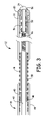
- FIG. 6 is a side view of a coil electrode illustrating a method for finishing ends of a flexible coil electrode, according to the present invention.
- FIG. 7 is front view of a coil electrode according to the present invention.
- FIG. 7A is a front view of a coil electrode according to the present invention.
- FIGS. 8 and 9 illustrate an alternative method for fixedly positioning an end of a flexible coil electrode, according to the present invention.
- FIG. 1 is a plan view of a bipolar cardiac vein lead having a flexible coil anode electrode in accordance with the present invention.
- a lead 10 includes a flexible, elongated lead body 16 extending between a proximal end 14 and a distal end 12 , and a tip electrode 20 positioned at distal lead end 12 .
- Tip electrode 20 is shown in FIG. 1 as being a ring tip electrode and may resemble the ring tip electrode disclosed in U.S. Pat. No. 5,342,414 issued to Mehra, incorporated herein by reference in its entirety.
- tip electrode 20 may alternatively be provided as a generally hemispherical electrode, a helical electrode, a barb or any other tip electrode known for use in cardiac leads.
- a monolithic controlled release device (MCRD) 22 may optionally be provided proximal to tip electrode 20 to elute an anti-inflammatory steroid to prevent degradation of the electrical properties at the electrode-tissue interface due to the body's inflammatory response.
- MCRD 22 may be provided as generally disclosed in U.S. Pat. No. 4,506,680 issued to Stokes or U.S. Pat. No. 4,972,848 issued to DiDomenico et al., both patents incorporated herein by reference in their entirety.
- a seal 24 may be provided at the distal end of lead 10 to prevent the ingress of body fluids into lead body 16 , which can pose a risk for infection.
- Seal 24 may be generally cup-shaped and may be provided as described in U.S. Pat. No. 6,192,280 issued to Sommer et al., incorporated herein by reference in its entirety. Alternatively, the seal 24 can be fabricated such that seal 24 is entirely contained within the distal end of the lead 10 .
- Alternative embodiments of a seal at or near the distal end of a medical lead or medical device that may be adapted for use with the present invention are disclosed in U.S. Pat. Application Ser. No. 20020016622 to Janke et al., and U.S. Pat. Application Ser. No. 20020077685 to Sundquist et al., both of which are incorporated herein by reference in their entirety, Other types of seals for preventing fluid from entering a tubular body of a medical device may also be used.
- Coil electrode 18 is spaced along lead body 16 spaced proximally from tip electrode 20 .
- Coil electrode 18 is preferably formed from a bifilar platinum iridium coil, though a multi-filar coil could also be used. A single filar coil electrode is conceivable, however, a bifilar or multi-filar coil provides redundancy, maintaining lead functionality should one filar fracture.
- Coil electrode 18 may be formed from any biocompatible conductive material, such as platinum, iridium, titanium, or alloys thereof. Coil 18 may be formed from wire that is generally round in cross-section or flat wire.
- coil electrode 18 is intended to serve as an anode electrode paired with the cathode tip electrode 20 for bipolar pacing and/or sensing. Anodal stimulation may also be achieved through coil electrode 18 when the energy of a delivered pacing pulse is adequately high.
- the length of coil electrode 18 is selected based on a desired electrode surface area suitable for the intended purpose and considering other design factors such as coil diameter, coil pitch, the surface area of each coil winding, etc. For example, an acceptable surface area for an anode coil electrode is approximately 30 to 40 square millimeters when used in conjunction with a cathode tip electrode having a surface area of approximately 5 to 6 square millimeters.
- Lead 10 includes a connector assembly 28 positioned at proximal end 14 of lead 10 .
- Connector assembly 28 includes two sets of sealing rings 38 for forming a fluid tight-seal within a connector bore of an associated implantable pacemaker.
- a connector pin 32 is electrically coupled via a conductor extending through lead body 16 to tip electrode 20 .
- Connector ring 30 is electrically coupled to coil electrode 18 via a second conductor extending through lead body 16 .
- a guidewire or stylet may be used to aid in deploying lead 10 .
- a guidewire 34 is shown entering proximal end 14 of lead 10 through hollow connector pin 32 and exiting the distal tip electrode 20 through seal 24 .
- the lead body 16 may be preformed with a curve or bend 26 to aid in guiding the lead to a desired implant site.
- a guidewire or stylet may be used to straighten lead 10 or to adjust the curvature of distal end 12 of lead 10 .
- FIG. 2 illustrates a multi-polar cardiac vein lead having tip electrode 20 and three flexible coil electrodes 18 , 19 and 21 for achieving bipolar pacing and/or sensing in the left ventricle and in the left atrium.
- the multi-polar lead of FIG. 2 includes some of the same elements numbered identically as in lead 10 of FIG. 1 .
- Coil electrode 18 may serve as an anode paired with the cathode tip electrode 20 as described above in conjunction with FIG. 1 .
- Coil electrodes 19 and 21 may serve as a bipolar pair for pacing and/or sensing in the left atrium or as a bipolar pair for pacing and/or sensing a second site along the left ventricle.
- the size of each coil electrode 18 , 19 , and 21 may be adjusted according to its intended purpose. For example, a relatively shorter coil electrode 19 may be provided, reducing the electrode surface area and thereby increasing pacing impedance, to serve as an anode paired with a relatively longer coil electrode 21 to serve as a cathode for pacing in the left atrium.
- Each coil electrode 18 , 19 and 21 is coupled via a corresponding conductor extending within lead body 16 to a corresponding ring connector 30 , 35 or 37 included in a proximal, quadrapolar connector assembly 29 .
- Multiple sets of sealing rings 38 serve to seal the connector assembly within the bore of an associated pacemaker and prevent fluid leakage between connector rings 30 , 35 and 37 and connector pin 32 .
- Tip electrode 20 is coupled, via a corresponding conductor, to connector pin 32 .
- the conductors extending within lead body 16 may be arranged concentrically with intervening layers of insulation, as generally described in U.S. Pat. No. 4,355,646 issued to Kallok, incorporated herein by reference in its entirety.
- lead body 17 may be provided as a multi-lumen lead body for carrying multiple conductors corresponding to each electrode 18 , 19 , 21 , and 22 .
- a suitable multi-lumen lead body is disclosed in U.S. Pat. No. 5,584,873 issued to Shoberg et al., incorporated herein by reference in its entirety.
- FIG. 3 is a side, cut-away view of a distal end of a lead having a flexible coil electrode in accordance with the present invention.
- lead body 16 includes an outer insulation sheath 40 and an inner insulation sheath 42 .
- Outer and inner insulation sheaths 40 and 42 are preferably formed from a biocompatible polymer such as polyurethane or silicone rubber.
- outer sheath 40 is formed from polyurethane and inner sheath 42 is formed from silicone rubber.
- Outer insulation sheath 40 is discontinuous in the region of coil electrode 18 , exposing electrode 18 to the surrounding tissue.
- Coil electrode 18 is electrically coupled to a conductive sleeve 48 by welding, crimping or another appropriate method.
- Sleeve 48 is formed from a biocompatible conductive metal such as stainless steel, platinum, or platinum alloys.
- the length of sleeve 48 is preferably minimized to limit the rigid length imposed on lead body 16 .
- the length of sleeve 48 is preferably no longer than the rigid length of tip electrode 20 , extending from a proximal end 23 of electrode 20 to a distal end 25 of electrode 20 , such that sleeve 48 is not a limiting factor in maneuvering lead 10 through a tortuous pathway.
- Conductive sleeve 48 is further electrically coupled to a coiled conductor 44 , which extends to connector ring 30 on proximal connector assembly 28 .
- a flexible polymer tube 50 may be provided inside the inner diameter of coil electrode 18 to provide structural support to coil electrode 18 .
- Polymer tube 50 is preferably bonded to outer insulation sheath 40 in areas where tube 50 and sheath 40 overlap.
- An adhesive such as silicone adhesive, may also be used to back fill open areas between windings of coil electrode 18 to provide a smooth surface on the outer diameter of coil electrode 18 .
- Inner insulation sheath 42 surrounds a coiled conductor 46 that is electrically coupled to tip electrode 20 .
- Seal 24 is molded onto internal sleeve 52 , which is preferably formed from a rigid, biocompatible, conductive material such as stainless steel, titanium, platinum, or titanium or platinum alloys.
- Internal sleeve 52 may alternatively be formed from a rigid, biocompatible, non-conductive material, such as polyurethane, Delrin or other high durometer polymer.
- Internal sleeve 52 is provided with an annular, laterally extending flange 54 . Seal 24 is retained by the interaction of flange 54 and tip electrode 20 .
- Internal sleeve 52 may act as a crimp core for crimping the shaft 56 of tip electrode 20 around coiled conductor 46 to establish electrical connection of tip electrode 20 to conductor 46 .
- a guidewire or stylet may be advanced through the center lumen of coiled conductor 46 and through internal sleeve 52 and seal 24 .
- Conductors 44 and 46 are shown as concentrically arranged coiled conductors and may be formed of MP35N alloy wire. Conductors 44 and 46 may alternatively be provided in the form of any of the numerous conductor types known for use in conjunction with cardiac pacing leads such as cabled or stranded conductors, for example as disclosed in U.S. Pat. No. 5,246,014, issued to Williams et al., incorporated herein by reference in its entirety, or non-concentric coils enclosed in a bitumen lead body, or a multi-filar coiled conductor wherein individual filars are insulated from each other and serve as separate conductors as disclosed in U.S. Pat. No. 4,944,088 issued to Doan, et al., incorporated herein by reference in its entirety.
- FIG. 3A is a side, cut-away view of a conductive sleeve of a lead according to an alternate embodiment of the present invention.
- sleeve 48 is provided with further flexibility by incorporating helical cuts, corrugations or other flexing mechanisms in sleeve 48 .
- spaced groove portions 49 are formed along sleeve 48 to provide sleeve 48 with increased flexibility.
- coiled conductor 44 is coupled to a flange portion 51 of sleeve 48 , using known coupling techniques, such as welding techniques, for example, to form a weld 55 along an upper portion 53 of flange 51 , fixedly engaging coiled conductor 44 to sleeve 48 at flange portion.
- groove portions 49 are cut at an angle corresponding to a pitch of coil electrode 18 in order to maximize the resulting flexibility of coiled conductor 18 .
- the present invention is intended to include groove portions 49 cut at any desired angle.
- FIG. 4 is side, cut-away view of an alternate embodiment of a coil electrode assembly according to the present invention.
- outer insulation sheath 40 is terminated exposing a distal segment 62 of a coiled conductor 60 that serves as a coil electrode.
- Exposed distal segment 62 of conductor 60 may serve as an anode or cathode with the exposed area corresponding to exposed distal segment 62 of conductor 60 varied depending on the desired electrode function of distal segment 62 .
- the present invention advantageously eliminates any rigid components needed for assembly of lead 10 , thus maintaining lead flexibility, reducing cost, and easing manufacturing processes.
- Coiled conductor 60 and electrode 62 are preferably formed from platinum iridium clad tantalum wire.
- Coil electrode 62 may resemble an outer conductor/indifferent electrode as generally disclosed in U.S. Pat. No. 6,321,123 B1, issued to Morris et al., incorporated herein by reference in its entirety.
- FIG. 5 is a side, cut-away view of an alternate embodiment of a coil electrode assembly of a lead according to the present invention.
- a proximal end 45 of coil electrode 18 extends over a distal end 47 of coiled conductor 44 to form an overlap area 66 , so that coil electrode 18 and coiled conductor 44 are electrically coupled directly to each other along overlap area 66 using welding techniques, for example.
- This method of assembly also eliminates additional rigid piece parts thus maintaining flexibility of the distal lead end.
- Outer insulation sheath 40 is discontinuous, exposing coil electrode 18 to the surrounding tissue.
- a polymer tube 50 positioned inside coil electrode 18 provides structural support and may be bonded to outer sheath 40 .
- FIG. 6 is a side view of a coil electrode illustrating a method for finishing ends of a flexible coil electrode, according to the present invention.
- each filar included in a bifilar coil is trimmed at a distal end and may be sculpt welded onto an adjacent filar.
- a distal end 70 of a filar 72 is welded to a filar 74 adjacent to filar 72 .
- FIG. 7 is front view of a coil electrode according to the present invention. As illustrated in FIGS. 6 and 7 , distal end 70 of filar 72 is trimmed and welded against filar 74 . Filar 74 is trimmed at distal end 76 , which is welded against filar 72 . Finishing the ends of coil electrode 18 in this way removes sharp edges and prevents the distal ends of filars 72 and 74 from becoming caught on anatomic structures during lead deployment. The proximal ends of filars 72 and 74 may be finished in the same manner as just described.
- proximal ends of the filars may not be necessary because the proximal ends may be contained within a weld pool when the proximal end of the coil electrode is welded to a conductor, as described in conjunction with FIG. 5 , or to a conductive sleeve, as described in conjunction with FIG. 3 .
- FIG. 7A is a front view of a coil electrode according to the present invention.
- coil electrode is a quadrafilar coil, including a first filar 71 having a distal end 73 , a second filar 75 having a distal end 77 , a third filar 79 having a distal end 81 , and a fourth filar 83 having a distal end 85
- distal end 73 is trimmed and welded against filar 75
- distal end 77 is trimmed and welded against filar 79
- distal end 81 is trimmed and welded against filar 83
- distal end 85 is trimmed and welded against filar 71 .
- conductor coil 18 is shown as being either a bifilar or quadrafilar coil, conductor coil 18 of the present invention could include any number of filars.
- welding of distal ends of filars described above is preferably performed using laser welding, although other welding techniques may also be utilized.
- FIGS. 8 and 9 illustrate an alternative method for fixedly positioning an end of a flexible coil electrode, according to the present invention.
- a multi-filar coil electrode 80 is mounted on a mandrel 82 that includes a handle 84 .
- Coil electrode 80 is advanced along mandrel 82 towards handle 84 so that a distal end portion 81 of coil electrode 80 is compressed against handle 84 as illustrated in FIG. 9 to form compressed filars 90 that are then joined by a continuous, radial weld.
- ends 73 , 77 , 81 , 85 of each of filars 71 , 75 , 79 , 83 are constrained within the weld pool and prevented from extending in a way that may cause damage to filars 71 , 75 , 79 , 83 or to surrounding tissue or lead components.
- ends 73 , 77 , 81 , 85 of filars 71 , 75 , 79 , 83 are preferably ground flush such that all of filars 71 , 75 , 79 , 83 end in a single cross-sectional plane.
- Filars 71 , 75 , 79 , 83 are ground flush, for example, by placing the distal end portion 81 of coil electrode 80 perpendicularly against a grinding wheel mounted on a rotary tool. Once ground flush, corresponding ends 73 , 77 , 81 , 85 of filars 71 , 75 , 79 , 83 are welded to adjacent filars, as described above in reference to FIG. 7A .
- the method depicted in FIGS. 8 and 9 is particularly advantageous when coil electrode 80 is formed from a multi-filar coil since each individual filar end does not need to be singly identified and welded.
- the mandrel 82 is preferably formed from a material that allows coil electrode 80 to be easily removed after welding is performed. Furthermore, the mandrel 82 is preferably formed from a material that will not contaminate the weld pool.
- a preferred mandrel material is molybdenum. Other materials, such as copper, have been found to leave contaminates in the weld pool and may adhere to the welded area of the coil making removal of the coil from the mandrel difficult.
Abstract
Description
Claims (15)
Priority Applications (5)
| Application Number | Priority Date | Filing Date | Title |
|---|---|---|---|
| US10/256,353 US7031777B2 (en) | 2002-09-27 | 2002-09-27 | Cardiac vein lead with flexible anode and method for forming same |
| EP03754903A EP1572290B1 (en) | 2002-09-27 | 2003-09-25 | Cardiac vein lead with flexible anode and method for forming same |
| CA002500227A CA2500227A1 (en) | 2002-09-27 | 2003-09-25 | Cardiac vein lead with flexible anode and method for forming same |
| PCT/US2003/030354 WO2004030747A2 (en) | 2002-09-27 | 2003-09-25 | Cardiac vein lead with flexible anode and method for forming same |
| JP2004541749A JP2006501028A (en) | 2002-09-27 | 2003-09-25 | Cardiac vein lead having a flexible anode and method of manufacturing the same |
Applications Claiming Priority (1)
| Application Number | Priority Date | Filing Date | Title |
|---|---|---|---|
| US10/256,353 US7031777B2 (en) | 2002-09-27 | 2002-09-27 | Cardiac vein lead with flexible anode and method for forming same |
Publications (2)
| Publication Number | Publication Date |
|---|---|
| US20040064173A1 US20040064173A1 (en) | 2004-04-01 |
| US7031777B2 true US7031777B2 (en) | 2006-04-18 |
Family
ID=32029260
Family Applications (1)
| Application Number | Title | Priority Date | Filing Date |
|---|---|---|---|
| US10/256,353 Expired - Lifetime US7031777B2 (en) | 2002-09-27 | 2002-09-27 | Cardiac vein lead with flexible anode and method for forming same |
Country Status (5)
| Country | Link |
|---|---|
| US (1) | US7031777B2 (en) |
| EP (1) | EP1572290B1 (en) |
| JP (1) | JP2006501028A (en) |
| CA (1) | CA2500227A1 (en) |
| WO (1) | WO2004030747A2 (en) |
Cited By (67)
| Publication number | Priority date | Publication date | Assignee | Title |
|---|---|---|---|---|
| US20050015132A1 (en) * | 2003-04-16 | 2005-01-20 | Itzhak Kronzon | Combined transesophageal echocardiography and transesophageal cardioversion probe |
| US20050288761A1 (en) * | 2004-06-24 | 2005-12-29 | Medtronic, Inc. | Multipolar medical electrical lead |
| US20060253180A1 (en) * | 2005-05-06 | 2006-11-09 | Cardiac Pacemakers, Inc. | Cable electrode assembly for a lead terminal and method therefor |
| US20070282411A1 (en) * | 2006-03-31 | 2007-12-06 | Brian Franz | Compliant electrical stimulation leads and methods of fabrication |
| US20090248127A1 (en) * | 2008-03-28 | 2009-10-01 | Medtronic, Inc. | Implantable medical electrical lead bodies providing improved electrode contact |
| US20100023097A1 (en) * | 2008-07-28 | 2010-01-28 | Boston Scientific Neuromodulation Corporation | System and method for increasing relative intensity between cathodes and anodes of neurostimulation system |
| US7676275B1 (en) * | 2005-05-02 | 2010-03-09 | Pacesetter, Inc. | Endovascular lead for chronic nerve stimulation |
| US20100137959A1 (en) * | 2008-11-29 | 2010-06-03 | Medtronic, Inc. | Medical electrical lead with backfilled electrode sub-assembly |
| US20100137954A1 (en) * | 2008-11-29 | 2010-06-03 | Medtronic, Inc. | Conductive couplings, and components thereof, for medical electrical leads |
| US20100137958A1 (en) * | 2008-11-29 | 2010-06-03 | Medtronic, Inc. | Medical electrical lead with embedded electrode sub-assembly |
| US20100133003A1 (en) * | 2008-11-29 | 2010-06-03 | Medtronic, Inc. | Implantable medical electrical leads including coil electrodes |
| US20100137964A1 (en) * | 2008-11-29 | 2010-06-03 | Medtronic, Inc. | Medical electrical lead joints and methods of manufacture |
| US7813805B1 (en) | 2006-01-11 | 2010-10-12 | Pacesetter, Inc. | Subcardiac threshold vagal nerve stimulation |
| US7869869B1 (en) | 2006-01-11 | 2011-01-11 | Pacesetter, Inc. | Subcardiac threshold vagal nerve stimulation |
| US8250754B2 (en) | 2008-11-29 | 2012-08-28 | Medtronic, Inc. | Method of manufacturing a medical electrical lead with insert-molded electrode |
| WO2013123367A1 (en) | 2012-02-17 | 2013-08-22 | Medtronic, Inc. | Criteria for optimal electrical resynchronization derived from multipolar leads or multiple electrodes during biventricular pacing |
| US8577476B2 (en) | 2010-03-09 | 2013-11-05 | Biotectix, LLC | Electrically conductive and mechanically supportive materials for biomedical leads |
| US8897879B2 (en) | 2011-11-04 | 2014-11-25 | Medtronic, Inc. | Method and apparatus for therapies of the cardiovascular and cardiorenal system |
| US8929984B2 (en) * | 2013-02-21 | 2015-01-06 | Medtronic, Inc. | Criteria for optimal electrical resynchronization during fusion pacing |
| US9155897B2 (en) | 2012-05-04 | 2015-10-13 | Medtronic, Inc. | Criteria for optimal electrical resynchronization during biventricular pacing |
| US9265951B2 (en) | 2010-02-12 | 2016-02-23 | The Brigham And Women's Hospital | System and method for automated adjustment of cardiac resynchronization therapy control parameters |
| US9265955B2 (en) | 2013-07-26 | 2016-02-23 | Medtronic, Inc. | Method and system for improved estimation of time of left ventricular pacing with respect to intrinsic right ventricular activation in cardiac resynchronization therapy |
| US9265954B2 (en) | 2013-07-26 | 2016-02-23 | Medtronic, Inc. | Method and system for improved estimation of time of left ventricular pacing with respect to intrinsic right ventricular activation in cardiac resynchronization therapy |
| US9278219B2 (en) | 2013-03-15 | 2016-03-08 | Medtronic, Inc. | Closed loop optimization of control parameters during cardiac pacing |
| US9278220B2 (en) | 2013-07-23 | 2016-03-08 | Medtronic, Inc. | Identification of healthy versus unhealthy substrate for pacing from a multipolar lead |
| US9282907B2 (en) | 2013-07-23 | 2016-03-15 | Medtronic, Inc. | Identification of healthy versus unhealthy substrate for pacing from a multipolar lead |
| US9320446B2 (en) | 2013-12-09 | 2016-04-26 | Medtronic, Inc. | Bioelectric sensor device and methods |
| US9474457B2 (en) | 2013-06-12 | 2016-10-25 | Medtronic, Inc. | Metrics of electrical dyssynchrony and electrical activation patterns from surface ECG electrodes |
| US9510763B2 (en) | 2011-05-03 | 2016-12-06 | Medtronic, Inc. | Assessing intra-cardiac activation patterns and electrical dyssynchrony |
| US9586052B2 (en) | 2014-08-15 | 2017-03-07 | Medtronic, Inc. | Systems and methods for evaluating cardiac therapy |
| US9586050B2 (en) | 2014-08-15 | 2017-03-07 | Medtronic, Inc. | Systems and methods for configuration of atrioventricular interval |
| US9591982B2 (en) | 2014-07-31 | 2017-03-14 | Medtronic, Inc. | Systems and methods for evaluating cardiac therapy |
| US9604064B2 (en) | 2013-02-21 | 2017-03-28 | Medtronic, Inc. | Criteria for optimal electrical resynchronization during fusion pacing |
| US9707400B2 (en) | 2014-08-15 | 2017-07-18 | Medtronic, Inc. | Systems, methods, and interfaces for configuring cardiac therapy |
| US9764143B2 (en) | 2014-08-15 | 2017-09-19 | Medtronic, Inc. | Systems and methods for configuration of interventricular interval |
| US9776009B2 (en) | 2014-03-20 | 2017-10-03 | Medtronic, Inc. | Non-invasive detection of phrenic nerve stimulation |
| US9877789B2 (en) | 2013-06-12 | 2018-01-30 | Medtronic, Inc. | Implantable electrode location selection |
| US9924884B2 (en) | 2013-04-30 | 2018-03-27 | Medtronic, Inc. | Systems, methods, and interfaces for identifying effective electrodes |
| US9986928B2 (en) | 2013-12-09 | 2018-06-05 | Medtronic, Inc. | Noninvasive cardiac therapy evaluation |
| US10064567B2 (en) | 2013-04-30 | 2018-09-04 | Medtronic, Inc. | Systems, methods, and interfaces for identifying optimal electrical vectors |
| US10251555B2 (en) | 2013-06-12 | 2019-04-09 | Medtronic, Inc. | Implantable electrode location selection |
| US10433746B2 (en) | 2017-12-22 | 2019-10-08 | Regents Of The University Of Minnesota | Systems and methods for anterior and posterior electrode signal analysis |
| US10456576B2 (en) | 2010-05-10 | 2019-10-29 | St. Jude Medical Luxembourg Holdings SMI S. A. R. L (“SJM LUX SMI”) | Methods, systems and devices for reducing migration |
| US10492705B2 (en) | 2017-12-22 | 2019-12-03 | Regents Of The University Of Minnesota | Anterior and posterior electrode signals |
| US10532213B2 (en) | 2017-03-03 | 2020-01-14 | Medtronic, Inc. | Criteria for determination of local tissue latency near pacing electrode |
| US10617318B2 (en) | 2018-02-27 | 2020-04-14 | Medtronic, Inc. | Mapping electrical activity on a model heart |
| US10668290B2 (en) | 2018-03-01 | 2020-06-02 | Medtronic, Inc. | Delivery of pacing therapy by a cardiac pacing device |
| US10773085B2 (en) | 2017-03-15 | 2020-09-15 | Medtronic, Inc. | QRS offset and onset determination |
| US10780279B2 (en) | 2016-02-26 | 2020-09-22 | Medtronic, Inc. | Methods and systems of optimizing right ventricular only pacing for patients with respect to an atrial event and left ventricular event |
| US10780281B2 (en) | 2018-03-23 | 2020-09-22 | Medtronic, Inc. | Evaluation of ventricle from atrium pacing therapy |
| US10786167B2 (en) | 2017-12-22 | 2020-09-29 | Medtronic, Inc. | Ectopic beat-compensated electrical heterogeneity information |
| US10799703B2 (en) | 2017-12-22 | 2020-10-13 | Medtronic, Inc. | Evaluation of his bundle pacing therapy |
| US10918870B2 (en) | 2018-03-07 | 2021-02-16 | Medtronic, Inc. | Atrial lead placement for treatment of atrial dyssynchrony |
| US10918863B2 (en) | 2017-07-28 | 2021-02-16 | Medtronic, Inc. | Generating activation times |
| US10940321B2 (en) | 2018-06-01 | 2021-03-09 | Medtronic, Inc. | Systems, methods, and interfaces for use in cardiac evaluation |
| US11219769B2 (en) | 2016-02-26 | 2022-01-11 | Medtronic, Inc. | Noninvasive methods and systems of determining the extent of tissue capture from cardiac pacing |
| US11253178B2 (en) | 2015-01-29 | 2022-02-22 | Medtronic, Inc. | Noninvasive assessment of cardiac resynchronization therapy |
| US11285312B2 (en) | 2018-03-29 | 2022-03-29 | Medtronic, Inc. | Left ventricular assist device adjustment and evaluation |
| US11304641B2 (en) | 2018-06-01 | 2022-04-19 | Medtronic, Inc. | Systems, methods, and interfaces for use in cardiac evaluation |
| US11419539B2 (en) | 2017-12-22 | 2022-08-23 | Regents Of The University Of Minnesota | QRS onset and offset times and cycle selection using anterior and posterior electrode signals |
| US11471678B2 (en) | 2017-07-28 | 2022-10-18 | Medtronic, Inc. | Cardiac cycle selection |
| US11497431B2 (en) | 2019-10-09 | 2022-11-15 | Medtronic, Inc. | Systems and methods for configuring cardiac therapy |
| US11547858B2 (en) | 2019-03-29 | 2023-01-10 | Medtronic, Inc. | Systems, methods, and devices for adaptive cardiac therapy |
| US11642533B2 (en) | 2019-11-04 | 2023-05-09 | Medtronic, Inc. | Systems and methods for evaluating cardiac therapy |
| US11697025B2 (en) | 2019-03-29 | 2023-07-11 | Medtronic, Inc. | Cardiac conduction system capture |
| US11801390B2 (en) | 2018-06-06 | 2023-10-31 | Medtronic, Inc. | Identification and adjustment for loss of effective cardiac resynchronization therapy |
| US11813464B2 (en) | 2020-07-31 | 2023-11-14 | Medtronic, Inc. | Cardiac conduction system evaluation |
Families Citing this family (30)
| Publication number | Priority date | Publication date | Assignee | Title |
|---|---|---|---|---|
| US20040249430A1 (en) * | 2003-06-03 | 2004-12-09 | Medtronic, Inc. | Implantable medical electrical lead |
| US20050080472A1 (en) * | 2003-10-10 | 2005-04-14 | Atkinson Robert Emmett | Lead stabilization devices and methods |
| US7546165B2 (en) * | 2005-12-19 | 2009-06-09 | Cardiac Pacemakers, Inc. | Interconnections of implantable lead conductors and electrodes and reinforcement therefor |
| US7801622B2 (en) | 2006-03-30 | 2010-09-21 | Medtronic, Inc. | Medical electrical lead and delivery system |
| US20080046059A1 (en) * | 2006-08-04 | 2008-02-21 | Zarembo Paul E | Lead including a heat fused or formed lead body |
| US7917229B2 (en) * | 2006-08-31 | 2011-03-29 | Cardiac Pacemakers, Inc. | Lead assembly including a polymer interconnect and methods related thereto |
| US7610101B2 (en) | 2006-11-30 | 2009-10-27 | Cardiac Pacemakers, Inc. | RF rejecting lead |
| JP5073829B2 (en) * | 2007-12-06 | 2012-11-14 | カーディアック ペースメイカーズ, インコーポレイテッド | Implantable lead with variable coil conductor pitch |
| EP2249920B1 (en) | 2008-02-06 | 2015-07-01 | Cardiac Pacemakers, Inc. | Lead with mri compatible design features |
| US8103360B2 (en) | 2008-05-09 | 2012-01-24 | Foster Arthur J | Medical lead coil conductor with spacer element |
| US8219209B2 (en) | 2008-08-15 | 2012-07-10 | Cardiac Pacemakers, Inc. | Implantable medical lead having reduced dimension tubing transition |
| WO2010104643A2 (en) | 2009-03-12 | 2010-09-16 | Cardiac Pacemakers, Inc. | Thin profile conductor assembly for medical device leads |
| EP2445577B1 (en) | 2009-06-26 | 2015-08-05 | Cardiac Pacemakers, Inc. | Medical device lead including a unifilar coil with improved torque transmission capacity and reduced mri heating |
| JP5886202B2 (en) * | 2009-09-23 | 2016-03-16 | レイク リージョン マニュファクチュアリング インコーポレイテッド | Guidewire type pacing lead |
| US8335572B2 (en) * | 2009-10-08 | 2012-12-18 | Cardiac Pacemakers, Inc. | Medical device lead including a flared conductive coil |
| US9254380B2 (en) | 2009-10-19 | 2016-02-09 | Cardiac Pacemakers, Inc. | MRI compatible tachycardia lead |
| AU2010337309B2 (en) * | 2009-12-30 | 2014-01-23 | Cardiac Pacemakers, Inc. | MRI-conditionally safe medical device lead |
| US8798767B2 (en) | 2009-12-31 | 2014-08-05 | Cardiac Pacemakers, Inc. | MRI conditionally safe lead with multi-layer conductor |
| US8391994B2 (en) | 2009-12-31 | 2013-03-05 | Cardiac Pacemakers, Inc. | MRI conditionally safe lead with low-profile multi-layer conductor for longitudinal expansion |
| US8825181B2 (en) | 2010-08-30 | 2014-09-02 | Cardiac Pacemakers, Inc. | Lead conductor with pitch and torque control for MRI conditionally safe use |
| US9198685B2 (en) | 2011-08-24 | 2015-12-01 | Gyrus Ent, L.L.C. | Surgical instrument with malleable tubing |
| WO2013066505A1 (en) | 2011-11-04 | 2013-05-10 | Cardiac Pacemakers, Inc. | Implantable medical device lead including inner coil reverse-wound relative to shocking coil |
| EP2838605A2 (en) | 2012-04-20 | 2015-02-25 | Cardiac Pacemakers, Inc. | Implantable medical device lead including a unifilar coiled cable |
| US8954168B2 (en) | 2012-06-01 | 2015-02-10 | Cardiac Pacemakers, Inc. | Implantable device lead including a distal electrode assembly with a coiled component |
| JP2015517383A (en) * | 2012-08-09 | 2015-06-22 | カーディアック ペースメイカーズ, インコーポレイテッド | Reinforced coil made from polymer-coated wire for improved torque transmission |
| US9180289B2 (en) | 2012-08-29 | 2015-11-10 | Cardiac Pacemakers, Inc. | Enhanced low friction coating for medical leads and methods of making |
| EP3156100B1 (en) | 2012-08-31 | 2019-05-01 | Cardiac Pacemakers, Inc. | Mri compatible lead coil |
| CN104736196B (en) | 2012-10-18 | 2017-06-16 | 心脏起搏器股份公司 | Sensing element for providing Magnetic resonance imaging compatibility in implantable medical device lead |
| US20170050017A1 (en) * | 2013-02-25 | 2017-02-23 | Cosman Medical, Inc. | Electrosurgical System |
| US9504821B2 (en) | 2014-02-26 | 2016-11-29 | Cardiac Pacemakers, Inc. | Construction of an MRI-safe tachycardia lead |
Citations (19)
| Publication number | Priority date | Publication date | Assignee | Title |
|---|---|---|---|---|
| US4355646A (en) | 1980-11-26 | 1982-10-26 | Medtronic, Inc. | Transvenous defibrillating lead |
| US4506680A (en) | 1983-03-17 | 1985-03-26 | Medtronic, Inc. | Drug dispensing body implantable lead |
| US4944088A (en) | 1988-05-25 | 1990-07-31 | Medtronic, Inc. | Ring electrode for multiconductor pacing leads |
| US4972848A (en) | 1989-08-23 | 1990-11-27 | Medtronic, Inc. | Medical electrical lead with polymeric monolithic controlled release device and method of manufacture |
| US5246014A (en) | 1991-11-08 | 1993-09-21 | Medtronic, Inc. | Implantable lead system |
| US5342414A (en) | 1993-07-01 | 1994-08-30 | Medtronic, Inc. | Transvenous defibrillation lead |
| US5466254A (en) | 1993-09-22 | 1995-11-14 | Pacesetter, Inc. | Coronary sinus lead with atrial sensing capability |
| US5584873A (en) | 1995-05-08 | 1996-12-17 | Medtronic, Inc. | Medical lead with compression lumens |
| US5676694A (en) | 1996-06-07 | 1997-10-14 | Medtronic, Inc. | Medical electrical lead |
| US5871530A (en) * | 1997-04-29 | 1999-02-16 | Medtronic, Inc. | Intracardiac defibrillation leads |
| US5928277A (en) * | 1998-02-19 | 1999-07-27 | Medtronic, Inc. | One piece defibrillation lead circuit |
| US5935160A (en) | 1997-01-24 | 1999-08-10 | Cardiac Pacemakers, Inc. | Left ventricular access lead for heart failure pacing |
| US6141593A (en) | 1998-11-10 | 2000-10-31 | Intermedics Inc. | Cardiac lead with ETEE coated DBS coil |
| US6192280B1 (en) | 1999-06-02 | 2001-02-20 | Medtronic, Inc. | Guidewire placed implantable lead with tip seal |
| US6295476B1 (en) * | 1999-11-01 | 2001-09-25 | Medtronic, Inc. | Medical lead conductor fracture visualization method and apparatus |
| US6321123B1 (en) | 1999-03-08 | 2001-11-20 | Medtronic Inc. | J-shaped coronary sinus lead |
| US20020016622A1 (en) | 1998-08-12 | 2002-02-07 | Cardiac Pacemakers, Inc. | Expandable seal for use with medical device and system |
| US20020077685A1 (en) | 2000-12-20 | 2002-06-20 | Medtronic, Inc. | Medical electrical lead and method of use |
| US6456888B1 (en) * | 2000-08-18 | 2002-09-24 | Cardiac Pacemakers, Inc. | Geometry for coupling and electrode to a conductor |
Family Cites Families (3)
| Publication number | Priority date | Publication date | Assignee | Title |
|---|---|---|---|---|
| US5174288A (en) * | 1990-11-30 | 1992-12-29 | Medtronic, Inc. | Method and apparatus for cardiac defibrillation |
| US6052625A (en) * | 1998-11-09 | 2000-04-18 | Medtronic, Inc. | Extractable implantable medical lead |
| US6408213B1 (en) * | 1999-09-29 | 2002-06-18 | Cardiac Pacemakers, Inc. | Low profile, ventricular, transvenous, epicardial defibrillation lead |
-
2002
- 2002-09-27 US US10/256,353 patent/US7031777B2/en not_active Expired - Lifetime
-
2003
- 2003-09-25 CA CA002500227A patent/CA2500227A1/en not_active Abandoned
- 2003-09-25 WO PCT/US2003/030354 patent/WO2004030747A2/en active Application Filing
- 2003-09-25 JP JP2004541749A patent/JP2006501028A/en active Pending
- 2003-09-25 EP EP03754903A patent/EP1572290B1/en not_active Expired - Lifetime
Patent Citations (19)
| Publication number | Priority date | Publication date | Assignee | Title |
|---|---|---|---|---|
| US4355646A (en) | 1980-11-26 | 1982-10-26 | Medtronic, Inc. | Transvenous defibrillating lead |
| US4506680A (en) | 1983-03-17 | 1985-03-26 | Medtronic, Inc. | Drug dispensing body implantable lead |
| US4944088A (en) | 1988-05-25 | 1990-07-31 | Medtronic, Inc. | Ring electrode for multiconductor pacing leads |
| US4972848A (en) | 1989-08-23 | 1990-11-27 | Medtronic, Inc. | Medical electrical lead with polymeric monolithic controlled release device and method of manufacture |
| US5246014A (en) | 1991-11-08 | 1993-09-21 | Medtronic, Inc. | Implantable lead system |
| US5342414A (en) | 1993-07-01 | 1994-08-30 | Medtronic, Inc. | Transvenous defibrillation lead |
| US5466254A (en) | 1993-09-22 | 1995-11-14 | Pacesetter, Inc. | Coronary sinus lead with atrial sensing capability |
| US5584873A (en) | 1995-05-08 | 1996-12-17 | Medtronic, Inc. | Medical lead with compression lumens |
| US5676694A (en) | 1996-06-07 | 1997-10-14 | Medtronic, Inc. | Medical electrical lead |
| US5935160A (en) | 1997-01-24 | 1999-08-10 | Cardiac Pacemakers, Inc. | Left ventricular access lead for heart failure pacing |
| US5871530A (en) * | 1997-04-29 | 1999-02-16 | Medtronic, Inc. | Intracardiac defibrillation leads |
| US5928277A (en) * | 1998-02-19 | 1999-07-27 | Medtronic, Inc. | One piece defibrillation lead circuit |
| US20020016622A1 (en) | 1998-08-12 | 2002-02-07 | Cardiac Pacemakers, Inc. | Expandable seal for use with medical device and system |
| US6141593A (en) | 1998-11-10 | 2000-10-31 | Intermedics Inc. | Cardiac lead with ETEE coated DBS coil |
| US6321123B1 (en) | 1999-03-08 | 2001-11-20 | Medtronic Inc. | J-shaped coronary sinus lead |
| US6192280B1 (en) | 1999-06-02 | 2001-02-20 | Medtronic, Inc. | Guidewire placed implantable lead with tip seal |
| US6295476B1 (en) * | 1999-11-01 | 2001-09-25 | Medtronic, Inc. | Medical lead conductor fracture visualization method and apparatus |
| US6456888B1 (en) * | 2000-08-18 | 2002-09-24 | Cardiac Pacemakers, Inc. | Geometry for coupling and electrode to a conductor |
| US20020077685A1 (en) | 2000-12-20 | 2002-06-20 | Medtronic, Inc. | Medical electrical lead and method of use |
Cited By (95)
| Publication number | Priority date | Publication date | Assignee | Title |
|---|---|---|---|---|
| US20050015132A1 (en) * | 2003-04-16 | 2005-01-20 | Itzhak Kronzon | Combined transesophageal echocardiography and transesophageal cardioversion probe |
| US20050288761A1 (en) * | 2004-06-24 | 2005-12-29 | Medtronic, Inc. | Multipolar medical electrical lead |
| US7225035B2 (en) * | 2004-06-24 | 2007-05-29 | Medtronic, Inc. | Multipolar medical electrical lead |
| US7676275B1 (en) * | 2005-05-02 | 2010-03-09 | Pacesetter, Inc. | Endovascular lead for chronic nerve stimulation |
| US20060253180A1 (en) * | 2005-05-06 | 2006-11-09 | Cardiac Pacemakers, Inc. | Cable electrode assembly for a lead terminal and method therefor |
| US7571010B2 (en) * | 2005-05-06 | 2009-08-04 | Cardiac Pacemakers, Inc. | Cable electrode assembly for a lead terminal and method therefor |
| US7813805B1 (en) | 2006-01-11 | 2010-10-12 | Pacesetter, Inc. | Subcardiac threshold vagal nerve stimulation |
| US7869869B1 (en) | 2006-01-11 | 2011-01-11 | Pacesetter, Inc. | Subcardiac threshold vagal nerve stimulation |
| US20070282411A1 (en) * | 2006-03-31 | 2007-12-06 | Brian Franz | Compliant electrical stimulation leads and methods of fabrication |
| US9844661B2 (en) | 2006-03-31 | 2017-12-19 | Advanced Neuromodulation Systems Inc. | Compliant electrical stimulation leads and methods of fabrication |
| US20090248127A1 (en) * | 2008-03-28 | 2009-10-01 | Medtronic, Inc. | Implantable medical electrical lead bodies providing improved electrode contact |
| US8041434B2 (en) | 2008-03-28 | 2011-10-18 | Medtronic, Inc. | Implantable medical electrical lead bodies providing improved electrode contact |
| US20100023097A1 (en) * | 2008-07-28 | 2010-01-28 | Boston Scientific Neuromodulation Corporation | System and method for increasing relative intensity between cathodes and anodes of neurostimulation system |
| US8660655B2 (en) * | 2008-07-28 | 2014-02-25 | Boston Scientific Neuromodulation Corporation | System and method for increasing relative intensity between cathodes and anodes of neurostimulation system |
| US8918179B2 (en) * | 2008-07-28 | 2014-12-23 | Boston Scientific Neuromodulation Corporation | System and method for increasing relative intensity between cathodes and anodes of neurostimulation system |
| US20140128956A1 (en) * | 2008-07-28 | 2014-05-08 | Boston Scientific Neuromodulation Corporation | System and method for increasing relative intensity between cathodes and anodes of neurostimulation system |
| US8494640B2 (en) * | 2008-07-28 | 2013-07-23 | Boston Scientific Neuromodulation Corporation | System and method for increasing relative intensity between cathodes and anodes of neurostimulation system |
| US20100137958A1 (en) * | 2008-11-29 | 2010-06-03 | Medtronic, Inc. | Medical electrical lead with embedded electrode sub-assembly |
| US8285395B2 (en) | 2008-11-29 | 2012-10-09 | Medtronic, Inc. | Conductive couplings, and components thereof, for medical electrical leads |
| US8437864B2 (en) | 2008-11-29 | 2013-05-07 | Medtronic, Inc. | Medical electrical lead with embedded electrode sub-assembly |
| US8442650B2 (en) | 2008-11-29 | 2013-05-14 | Medtronic, Inc. | Medical electrical lead with backfilled electrode sub-assembly |
| US20100137954A1 (en) * | 2008-11-29 | 2010-06-03 | Medtronic, Inc. | Conductive couplings, and components thereof, for medical electrical leads |
| US20100137959A1 (en) * | 2008-11-29 | 2010-06-03 | Medtronic, Inc. | Medical electrical lead with backfilled electrode sub-assembly |
| US20100137964A1 (en) * | 2008-11-29 | 2010-06-03 | Medtronic, Inc. | Medical electrical lead joints and methods of manufacture |
| US8250754B2 (en) | 2008-11-29 | 2012-08-28 | Medtronic, Inc. | Method of manufacturing a medical electrical lead with insert-molded electrode |
| US10535446B2 (en) | 2008-11-29 | 2020-01-14 | Medtronic, Inc. | Medical electrical lead joints and methods of manufacture |
| US20100133003A1 (en) * | 2008-11-29 | 2010-06-03 | Medtronic, Inc. | Implantable medical electrical leads including coil electrodes |
| US9265951B2 (en) | 2010-02-12 | 2016-02-23 | The Brigham And Women's Hospital | System and method for automated adjustment of cardiac resynchronization therapy control parameters |
| US9050454B2 (en) | 2010-03-09 | 2015-06-09 | Biotectix, LLC | Electrically conductive and mechanically supportive polymer materials for biomedical leads |
| US8577476B2 (en) | 2010-03-09 | 2013-11-05 | Biotectix, LLC | Electrically conductive and mechanically supportive materials for biomedical leads |
| US11413451B2 (en) | 2010-05-10 | 2022-08-16 | St. Jude Medical Luxembourg Holdings SMI S.A.R.L. (“SJM LUX SMI”) | Methods, systems and devices for reducing migration |
| US10456576B2 (en) | 2010-05-10 | 2019-10-29 | St. Jude Medical Luxembourg Holdings SMI S. A. R. L (“SJM LUX SMI”) | Methods, systems and devices for reducing migration |
| US9974457B2 (en) | 2011-05-03 | 2018-05-22 | Medtronic, Inc. | Assessing intra-cardiac activation patterns |
| US11027135B2 (en) | 2011-05-03 | 2021-06-08 | Medtronic, Inc. | Assessing intra-cardiac activation patterns |
| US9962097B2 (en) | 2011-05-03 | 2018-05-08 | Medtronic, Inc. | Assessing intra-cardiac activation patterns and electrical dyssynchrony |
| US9510763B2 (en) | 2011-05-03 | 2016-12-06 | Medtronic, Inc. | Assessing intra-cardiac activation patterns and electrical dyssynchrony |
| US8897879B2 (en) | 2011-11-04 | 2014-11-25 | Medtronic, Inc. | Method and apparatus for therapies of the cardiovascular and cardiorenal system |
| WO2013123386A1 (en) | 2012-02-17 | 2013-08-22 | Medtronic, Inc. | Criteria for optimal electrical resynchronization derived from multipolar leads or multiple electrodes during biventricular pacing |
| US9511234B2 (en) | 2012-02-17 | 2016-12-06 | Medtronic, Inc. | Criteria for optimal electrical resynchronization derived from multipolar leads or multiple electrodes during biventricular pacing |
| WO2013123367A1 (en) | 2012-02-17 | 2013-08-22 | Medtronic, Inc. | Criteria for optimal electrical resynchronization derived from multipolar leads or multiple electrodes during biventricular pacing |
| US9155897B2 (en) | 2012-05-04 | 2015-10-13 | Medtronic, Inc. | Criteria for optimal electrical resynchronization during biventricular pacing |
| US9700729B2 (en) | 2012-05-04 | 2017-07-11 | Medtronic, Inc. | Criteria for optimal electrical resynchronization during biventricular pacing |
| US9604064B2 (en) | 2013-02-21 | 2017-03-28 | Medtronic, Inc. | Criteria for optimal electrical resynchronization during fusion pacing |
| US8929984B2 (en) * | 2013-02-21 | 2015-01-06 | Medtronic, Inc. | Criteria for optimal electrical resynchronization during fusion pacing |
| US9649497B2 (en) | 2013-03-15 | 2017-05-16 | Medtronic, Inc. | Closed loop optimization of control parameters during cardiac pacing |
| US9278219B2 (en) | 2013-03-15 | 2016-03-08 | Medtronic, Inc. | Closed loop optimization of control parameters during cardiac pacing |
| US11648406B2 (en) | 2013-04-30 | 2023-05-16 | Medtronic, Inc. | Systems, methods, and interfaces for identifying effective electrodes |
| US9931048B2 (en) | 2013-04-30 | 2018-04-03 | Medtronic, Inc. | Systems, methods, and interfaces for identifying effective electrodes |
| US10064567B2 (en) | 2013-04-30 | 2018-09-04 | Medtronic, Inc. | Systems, methods, and interfaces for identifying optimal electrical vectors |
| US9924884B2 (en) | 2013-04-30 | 2018-03-27 | Medtronic, Inc. | Systems, methods, and interfaces for identifying effective electrodes |
| US9486151B2 (en) | 2013-06-12 | 2016-11-08 | Medtronic, Inc. | Metrics of electrical dyssynchrony and electrical activation patterns from surface ECG electrodes |
| US9474457B2 (en) | 2013-06-12 | 2016-10-25 | Medtronic, Inc. | Metrics of electrical dyssynchrony and electrical activation patterns from surface ECG electrodes |
| US9877789B2 (en) | 2013-06-12 | 2018-01-30 | Medtronic, Inc. | Implantable electrode location selection |
| US10251555B2 (en) | 2013-06-12 | 2019-04-09 | Medtronic, Inc. | Implantable electrode location selection |
| US9278220B2 (en) | 2013-07-23 | 2016-03-08 | Medtronic, Inc. | Identification of healthy versus unhealthy substrate for pacing from a multipolar lead |
| US9282907B2 (en) | 2013-07-23 | 2016-03-15 | Medtronic, Inc. | Identification of healthy versus unhealthy substrate for pacing from a multipolar lead |
| US9265954B2 (en) | 2013-07-26 | 2016-02-23 | Medtronic, Inc. | Method and system for improved estimation of time of left ventricular pacing with respect to intrinsic right ventricular activation in cardiac resynchronization therapy |
| US9265955B2 (en) | 2013-07-26 | 2016-02-23 | Medtronic, Inc. | Method and system for improved estimation of time of left ventricular pacing with respect to intrinsic right ventricular activation in cardiac resynchronization therapy |
| US10368766B2 (en) | 2013-12-09 | 2019-08-06 | Medtronic, Inc. | Bioelectric sensor device and methods |
| US9993172B2 (en) | 2013-12-09 | 2018-06-12 | Medtronic, Inc. | Noninvasive cardiac therapy evaluation |
| US9986928B2 (en) | 2013-12-09 | 2018-06-05 | Medtronic, Inc. | Noninvasive cardiac therapy evaluation |
| US10206601B2 (en) | 2013-12-09 | 2019-02-19 | Medtronic, Inc. | Noninvasive cardiac therapy evaluation |
| US9320446B2 (en) | 2013-12-09 | 2016-04-26 | Medtronic, Inc. | Bioelectric sensor device and methods |
| US11456062B2 (en) | 2013-12-09 | 2022-09-27 | Medtronic, Inc. | Noninvasive cardiac therapy evaluation |
| US9776009B2 (en) | 2014-03-20 | 2017-10-03 | Medtronic, Inc. | Non-invasive detection of phrenic nerve stimulation |
| US9591982B2 (en) | 2014-07-31 | 2017-03-14 | Medtronic, Inc. | Systems and methods for evaluating cardiac therapy |
| US9764143B2 (en) | 2014-08-15 | 2017-09-19 | Medtronic, Inc. | Systems and methods for configuration of interventricular interval |
| US9707400B2 (en) | 2014-08-15 | 2017-07-18 | Medtronic, Inc. | Systems, methods, and interfaces for configuring cardiac therapy |
| US9586052B2 (en) | 2014-08-15 | 2017-03-07 | Medtronic, Inc. | Systems and methods for evaluating cardiac therapy |
| US9586050B2 (en) | 2014-08-15 | 2017-03-07 | Medtronic, Inc. | Systems and methods for configuration of atrioventricular interval |
| US11253178B2 (en) | 2015-01-29 | 2022-02-22 | Medtronic, Inc. | Noninvasive assessment of cardiac resynchronization therapy |
| US11219769B2 (en) | 2016-02-26 | 2022-01-11 | Medtronic, Inc. | Noninvasive methods and systems of determining the extent of tissue capture from cardiac pacing |
| US10780279B2 (en) | 2016-02-26 | 2020-09-22 | Medtronic, Inc. | Methods and systems of optimizing right ventricular only pacing for patients with respect to an atrial event and left ventricular event |
| US10532213B2 (en) | 2017-03-03 | 2020-01-14 | Medtronic, Inc. | Criteria for determination of local tissue latency near pacing electrode |
| US10773085B2 (en) | 2017-03-15 | 2020-09-15 | Medtronic, Inc. | QRS offset and onset determination |
| US11471678B2 (en) | 2017-07-28 | 2022-10-18 | Medtronic, Inc. | Cardiac cycle selection |
| US10918863B2 (en) | 2017-07-28 | 2021-02-16 | Medtronic, Inc. | Generating activation times |
| US10786167B2 (en) | 2017-12-22 | 2020-09-29 | Medtronic, Inc. | Ectopic beat-compensated electrical heterogeneity information |
| US10433746B2 (en) | 2017-12-22 | 2019-10-08 | Regents Of The University Of Minnesota | Systems and methods for anterior and posterior electrode signal analysis |
| US10799703B2 (en) | 2017-12-22 | 2020-10-13 | Medtronic, Inc. | Evaluation of his bundle pacing therapy |
| US10492705B2 (en) | 2017-12-22 | 2019-12-03 | Regents Of The University Of Minnesota | Anterior and posterior electrode signals |
| US11419539B2 (en) | 2017-12-22 | 2022-08-23 | Regents Of The University Of Minnesota | QRS onset and offset times and cycle selection using anterior and posterior electrode signals |
| US10617318B2 (en) | 2018-02-27 | 2020-04-14 | Medtronic, Inc. | Mapping electrical activity on a model heart |
| US10668290B2 (en) | 2018-03-01 | 2020-06-02 | Medtronic, Inc. | Delivery of pacing therapy by a cardiac pacing device |
| US10918870B2 (en) | 2018-03-07 | 2021-02-16 | Medtronic, Inc. | Atrial lead placement for treatment of atrial dyssynchrony |
| US10780281B2 (en) | 2018-03-23 | 2020-09-22 | Medtronic, Inc. | Evaluation of ventricle from atrium pacing therapy |
| US11285312B2 (en) | 2018-03-29 | 2022-03-29 | Medtronic, Inc. | Left ventricular assist device adjustment and evaluation |
| US11304641B2 (en) | 2018-06-01 | 2022-04-19 | Medtronic, Inc. | Systems, methods, and interfaces for use in cardiac evaluation |
| US10940321B2 (en) | 2018-06-01 | 2021-03-09 | Medtronic, Inc. | Systems, methods, and interfaces for use in cardiac evaluation |
| US11801390B2 (en) | 2018-06-06 | 2023-10-31 | Medtronic, Inc. | Identification and adjustment for loss of effective cardiac resynchronization therapy |
| US11547858B2 (en) | 2019-03-29 | 2023-01-10 | Medtronic, Inc. | Systems, methods, and devices for adaptive cardiac therapy |
| US11697025B2 (en) | 2019-03-29 | 2023-07-11 | Medtronic, Inc. | Cardiac conduction system capture |
| US11497431B2 (en) | 2019-10-09 | 2022-11-15 | Medtronic, Inc. | Systems and methods for configuring cardiac therapy |
| US11642533B2 (en) | 2019-11-04 | 2023-05-09 | Medtronic, Inc. | Systems and methods for evaluating cardiac therapy |
| US11813464B2 (en) | 2020-07-31 | 2023-11-14 | Medtronic, Inc. | Cardiac conduction system evaluation |
Also Published As
| Publication number | Publication date |
|---|---|
| EP1572290B1 (en) | 2013-02-27 |
| CA2500227A1 (en) | 2004-04-15 |
| WO2004030747A3 (en) | 2005-08-18 |
| EP1572290A2 (en) | 2005-09-14 |
| WO2004030747A2 (en) | 2004-04-15 |
| US20040064173A1 (en) | 2004-04-01 |
| JP2006501028A (en) | 2006-01-12 |
| EP1572290A3 (en) | 2005-10-05 |
Similar Documents
| Publication | Publication Date | Title |
|---|---|---|
| US7031777B2 (en) | Cardiac vein lead with flexible anode and method for forming same | |
| US7313445B2 (en) | Medical lead with flexible distal guidewire extension | |
| US6968237B2 (en) | Implantable coronary sinus lead and lead system | |
| US7860580B2 (en) | Active fixation medical electrical lead | |
| US9907952B2 (en) | Active fixation medical electrical lead | |
| US6456888B1 (en) | Geometry for coupling and electrode to a conductor | |
| US7720550B2 (en) | High impedance active fixation electrode of an electrical medical lead | |
| US6973352B1 (en) | Steerable cardiac pacing and sensing catheter and guidewire for implanting leads | |
| US5800496A (en) | Medical electrical lead having a crush resistant lead body | |
| US7187980B2 (en) | Cardiac lead with steroid eluting ring | |
| US20040102830A1 (en) | System for coupling an implanatable medical device to an epicardial site | |
| US20060293737A1 (en) | Multiple electrode implantable lead | |
| CN102065947A (en) | Bundle of his stimulation system | |
| WO1992016254A1 (en) | Transvenous defibrillation lead and method of use | |
| JP2013516240A (en) | Implantable lead with conductor coil having two or more sections | |
| US20040249430A1 (en) | Implantable medical electrical lead | |
| EP3870268B1 (en) | Configurations and constructions for active fixation implantable medical electrical leads |
Legal Events
| Date | Code | Title | Description |
|---|---|---|---|
| AS | Assignment |
Owner name: MEDTRONIC, INC., MINNESOTA Free format text: ASSIGNMENT OF ASSIGNORS INTEREST;ASSIGNORS:HINE, DOUGLAS S.;BASS, WAYNE R.;MCINTYRE, PETER B.;AND OTHERS;REEL/FRAME:013729/0771;SIGNING DATES FROM 20020116 TO 20021213 |
|
| FEPP | Fee payment procedure |
Free format text: PAYOR NUMBER ASSIGNED (ORIGINAL EVENT CODE: ASPN); ENTITY STATUS OF PATENT OWNER: LARGE ENTITY |
|
| STCF | Information on status: patent grant |
Free format text: PATENTED CASE |
|
| FPAY | Fee payment |
Year of fee payment: 4 |
|
| FPAY | Fee payment |
Year of fee payment: 8 |
|
| MAFP | Maintenance fee payment |
Free format text: PAYMENT OF MAINTENANCE FEE, 12TH YEAR, LARGE ENTITY (ORIGINAL EVENT CODE: M1553) Year of fee payment: 12 |