US7038441B2 - Test apparatus with loading device - Google Patents
Test apparatus with loading device Download PDFInfo
- Publication number
- US7038441B2 US7038441B2 US10/677,524 US67752403A US7038441B2 US 7038441 B2 US7038441 B2 US 7038441B2 US 67752403 A US67752403 A US 67752403A US 7038441 B2 US7038441 B2 US 7038441B2
- Authority
- US
- United States
- Prior art keywords
- chuck
- carriage
- receiving
- test apparatus
- holding
- Prior art date
- Legal status (The legal status is an assumption and is not a legal conclusion. Google has not performed a legal analysis and makes no representation as to the accuracy of the status listed.)
- Active, expires
Links
Images


Classifications
-
- G—PHYSICS
- G01—MEASURING; TESTING
- G01R—MEASURING ELECTRIC VARIABLES; MEASURING MAGNETIC VARIABLES
- G01R31/00—Arrangements for testing electric properties; Arrangements for locating electric faults; Arrangements for electrical testing characterised by what is being tested not provided for elsewhere
- G01R31/28—Testing of electronic circuits, e.g. by signal tracer
- G01R31/2851—Testing of integrated circuits [IC]
- G01R31/2855—Environmental, reliability or burn-in testing
- G01R31/286—External aspects, e.g. related to chambers, contacting devices or handlers
- G01R31/2865—Holding devices, e.g. chucks; Handlers or transport devices
-
- G—PHYSICS
- G01—MEASURING; TESTING
- G01R—MEASURING ELECTRIC VARIABLES; MEASURING MAGNETIC VARIABLES
- G01R31/00—Arrangements for testing electric properties; Arrangements for locating electric faults; Arrangements for electrical testing characterised by what is being tested not provided for elsewhere
- G01R31/28—Testing of electronic circuits, e.g. by signal tracer
- G01R31/2851—Testing of integrated circuits [IC]
- G01R31/2886—Features relating to contacting the IC under test, e.g. probe heads; chucks
- G01R31/2887—Features relating to contacting the IC under test, e.g. probe heads; chucks involving moving the probe head or the IC under test; docking stations
-
- G—PHYSICS
- G01—MEASURING; TESTING
- G01R—MEASURING ELECTRIC VARIABLES; MEASURING MAGNETIC VARIABLES
- G01R31/00—Arrangements for testing electric properties; Arrangements for locating electric faults; Arrangements for electrical testing characterised by what is being tested not provided for elsewhere
- G01R31/28—Testing of electronic circuits, e.g. by signal tracer
- G01R31/2801—Testing of printed circuits, backplanes, motherboards, hybrid circuits or carriers for multichip packages [MCP]
- G01R31/2806—Apparatus therefor, e.g. test stations, drivers, analysers, conveyors
-
- G—PHYSICS
- G01—MEASURING; TESTING
- G01R—MEASURING ELECTRIC VARIABLES; MEASURING MAGNETIC VARIABLES
- G01R31/00—Arrangements for testing electric properties; Arrangements for locating electric faults; Arrangements for electrical testing characterised by what is being tested not provided for elsewhere
- G01R31/28—Testing of electronic circuits, e.g. by signal tracer
- G01R31/282—Testing of electronic circuits specially adapted for particular applications not provided for elsewhere
- G01R31/2831—Testing of materials or semi-finished products, e.g. semiconductor wafers or substrates
Definitions
- the invention relates to a test apparatus with loading device, which has a chuck which has a bearing surface for a test substrate, comprising a substrate carrier and component which is to be tested, and is provided with a chuck drive.
- the chuck can be displaced within a working area by means of the chuck drive.
- there is a receiving member for receiving test substrates which can be displaced from a first position within a working area of the chuck to a second receiving position outside the working area.
- Test substrates comprise a substrate carrier, on which components which are to be tested are arranged.
- Components of this type may be semiconductor chips. If these semiconductor chips are tested while they are still on the semiconductor wafer, i.e. while they are still joined to the wafer, the semiconductor wafer itself forms the substrate carrier.
- test substrates may also be other components, such as individual semiconductor chips, hybrid components, micromechanical components and the like. In this case, the test substrates are arranged on the substrate carrier during testing.
- Each substrate carrier has a smooth and planar underside for resting on the bearing surface of the chuck.
- test substrates such as for example semiconductor chips which are still joined to semiconductor wafers, i.e. to test the operational reliability of the semiconductor chips
- the latter are brought into contact with contact-making needles, then electrical signals are applied to them via these contact-making needles and the electrical reaction is measured.
- the optical reaction of the semiconductor chips it is also possible to test for the optical reaction of the semiconductor chips to the electrical signals or the electrical reaction of the semiconductor chips to the application of light or other radiation. Testing of this type is carried out in a test apparatus, in which the semiconductor wafers are placed onto a wafer receiver, known as a chuck, and are held on the latter.
- the chuck is located on an X-Y table, so that the semiconductor wafer can be positioned relative to the contact-making needles.
- Test apparatus are used to test substrates under different environmental conditions.
- the chuck is surrounded by a housing, inside which it can move freely.
- This housing allows a controlled atmosphere to be established.
- the housing can also be used to provide a shield from undesired electromagnetic radiation.
- the chuck is used not only to receive the test substrates but also to perform several further functions, such as heating or cooling of the test substrates or the setting of a controlled potential.
- the chuck is provided with media lines for external connection to corresponding media sources.
- the chuck has to be provided with a test substrate, i.e. has to be loaded, before testing is carried out.
- Loading devices are used for this purpose.
- a loading device is known for use on a test apparatus produced by Cascade Microtec Inc., in which a guide carriage, by means of which the chuck can be detached from the X-Y table and moved out of the housing, is provided on the X-Y table.
- a flap which allows the chuck to move out is provided in the housing.
- the chuck For loading purposes, the chuck is moved out of the housing on the guide carriage, through the flap, so that it moves to a receiving position.
- the receiving position is located on a side of the test apparatus on which an operator usually stands.
- a semiconductor wafer is placed onto the chuck by means of forceps.
- the chuck is moved back in until it has returned to its position above the X-Y table, before then being displaced with the X-Y table for positioning of the contact-making needles.
- the flap is closed again.
- the chuck itself forms the receiving means which is moved from the working area of the chuck into the receiving position.
- the chuck it should be noted that before the chuck is moved out to the receiving position, it adopts a position within its working area which is closest to the receiving position, in order to keep the displacement distances as short as possible.
- a first drawback of this solution is that the chuck has to cover relatively long displacement paths. In this case, all the media lines have to follow this long movement of the chuck and themselves have to be made relatively long. In particular refrigerant lines are relatively rigid and therefore impede the movement of the chuck out of the housing and also the movement of the chuck on the X-Y table. This adversely affects the accuracy of the movement.
- a second drawback is that it has to be possible to detach the chuck from the X-Y table, since this entails additional instability and therefore inaccuracies.
- a third drawback is that in this solution the chuck has to be moved out of the housing even in situations in which it has to perform cooling functions. In the process, it is then exposed to the open ambient atmosphere, from which moisture will precipitate on the cold chuck, leading to an extremely undesirable introduction of moisture into the housing.
- the invention is therefore based on the object of increasing the accuracy of the movement of the chuck. Moreover, in the case of test apparatus with a controlled atmosphere, a further object is to prevent the chuck from being exposed to the open-air atmosphere.
- a carriage which can be displaced between a first position close to the chuck, in which the chuck is located in a position inside the working area, and the receiving position.
- the carriage is provided with a receiving member, in which the test substrate can be at least indirectly inserted in such a way that the test substrate, when the carriage is in the position close to the chuck, is located above the chuck.
- the holder and the chuck can move vertically relative to one another when the carriage is in the position close to the chuck.
- test substrate This allows the carriage to move out of its first position close to the chuck to the receiving position, where it is provided with a test substrate. This can be effected in such a manner that the test substrate is placed directly into the receiving member. However, it is also possible for the test substrate to be connected to the receiving member by further member being connected between them.
- the carriage can move back from the receiving position into the position close to the chuck. This causes the test substrate to move to above the receiving surface of the chuck. The relative movement between chuck and receiving member causes the receiving surface to come into contact with the underside of the test substrate, with the result that the test substrate is transferred to the chuck.
- the working area of the chuck in one configuration of the invention, there is provision for the working area of the chuck to be surrounded by a housing.
- the receiving position lies outside the housing.
- An opening, which can be closed off by a flap, is provided in the housing.
- This housing is used to create a controlled environment around the chuck, allowing the test substrate to be tested under various conditions, such as very low temperatures or under a vacuum. It is necessary for the controlled environment to be established during testing. This is ensured by virtue of the fact that the flap can be closed again after the test substrate has been moved into the housing.
- a test substrate can be mounted on the holder in the open-air atmosphere, preferably on the operator side of the test apparatus.
- the carriage has a dedicated carriage drive, which is connected to the chuck drive. This allows short displacement paths of the carriage to be achieved, by virtue of the fact that when a test substrate is being discharged or received, the chuck moves into a position which is as close as possible to the receiving position. The carriage can then move from this close position into the receiving position.
- the carriage in another embodiment, there is provision for the carriage to have a carriage drive which is connected to the housing. This completely decouples the carriage drive from the chuck. For test substrates to be transferred, the chuck then moves into a defined position which represents the position of the carriage which is close to the chuck. The chuck is then held in this position until the transfer has been effected.
- the carriage or the carriage drive to be provided with a dedicated vertical drive, by means of which the carriage can be moved vertically relative to the chuck.
- the vertical relative movement can also be realized without a dedicated vertical drive for the carriage, by means of a vertical movement of the chuck, since the chuck is always configured such that it can be moved both horizontally and vertically, i.e. it generally has a dedicated vertical drive.
- the carriage is arranged below a plane in which the bearing surface lies.
- the latter to allow simple realization of the carriage there is provision for the latter to comprise at least one telescopic rail arranged laterally adjacent to the chuck.
- the receiving member can then be introduced into this telescopic rail; in the case of a telescopic rail, the holder is actually suspended therefrom.
- the receiving member is provided with a forceps holder for receiving forceps which hold the test substrate.
- the chuck has at least three lifting pins, which can move perpendicular to the bearing surface between a first position, in which the tip of each pin at the upper end of each pin lies in or below the bearing surface, and a second position, in which the tip of each pin is located a certain amount above the bearing surface.
- Test substrates are usually handled using forceps. These forceps engage beneath the test substrates on the underside by using a vacuum suction surface. A vacuum is then applied to this suction surface. This can be effected, for example, by means of a vacuum pump in the forceps. In this way, any manual contact, which always entails a high risk of fracture or contamination, is avoided. Forceps of this type can then be placed directly into the forceps holder, where they are moved to above the receiving surface of the chuck together with the test substrate. The vertical relative movement between holder and chuck then causes the underside of the test substrate to come into contact with the tips of the lifting pins, which are located in their second, i.e. extended position. This allows the forceps to be detached from the test substrate, e.g. through the application of air to the vacuum suction surface.
- the apparatus which release the forceps from the test substrate will expediently be located in the vicinity of the receiving position even when the carriage is retracted, i.e. when it is located in the position close to the chuck, so that they can readily be handled by an operator.
- This can be achieved, for example, by virtue of the fact that the forceps have an elongated shank, preferably of a length which is greater than the displacement path of the carriage.
- Suitable operating means for example, a valve or an actuating switch for a valve or other unlocking means, can then be arranged on this shank.
- the forceps After the forceps have been detached, they can be removed from the test substrate, since the extended pins set a distance between the bearing surface and the underside of the test substrate. The forceps can then move freely within this space and can be pulled out. This can be effected by means of the carriage, to the forceps holder of which the forceps are still secured. The carriage can therefore move the forceps back to the receiving position, where the operator again detaches the forceps from the holder. The carriage is then moved back into the housing.
- the lifting pins are moved into their first position, so that the underside of the test substrate comes into contact with the bearing surface.
- the chuck has thus been loaded with the test substrate. The above steps are performed in the reverse order for the purpose of removing the test substrate.
- the forceps holder is expedient for the forceps holder to be provided with a vertical support, with the forceps holder at a vertical distance from the carriage. This ensures that the test substrate is held at the height of the bearing surface by the forceps.
- the chuck comprises a chuck body with a chuck surface and a chuck plate which rests on the chuck surface.
- the chuck plate is provided with the bearing surface and can be detached from the chuck body.
- the chuck plate has at least three lugs projecting above the chuck surface.
- the holder has an opening, which has an opening surface area which is similar to the chuck surface, such that the holder, in the position close to the chuck, at least partially engages around the chuck body without contact and at a distance therefrom which is smaller than the extent to which the lugs project above the chuck surface.
- the opening area allows the receiving member to move vertically relative to the chuck while at least partially engaging around the chuck. If a vertical relative movement is then carried out, the receiving member engages beneath the lugs of the chuck plate and lifts them off the chuck surface. The movement of the carriage toward the receiving position can then take place. Then, at this receiving position, a test substrate is placed onto the bearing surface located on the chuck plate. Next, the carriage together with receiving member, chuck plate and test substrate is moved back into the position close to the chuck, where the chuck plate with the test substrate resting on the bearing surface is placed onto the chuck surface, once again through the execution of a vertical relative movement. In this way, the chuck is loaded with the test substrate.
- One possible configuration of the chuck plate consists in the lugs being joined integrally to the chuck plate.
- the lugs may form separate components which are fixedly connected to the chuck plate.
- the receiving member is expediently designed in such a manner that the receiving member comprises a plate in which the opening surface area is formed.
- the chuck once again comprises a chuck body with a chuck surface and a chuck plate which rests on the chuck surface, is provided with the bearing surface and can be detached from the chuck body.
- the chuck plate on its underside, has first holding members, which engage releasably in second holding members, which are connected to the chuck.
- the carriage can be pushed in from the outside from the receiving position.
- the carriage has a third holding member, which engages releasably into a fourth holding member on the chuck plate.
- the carriage is mounted outside the test apparatus and is only pushed in for loading purposes. This prevents, for example, moisture from being introduced by the carriage if the latter were, for example, to become cold inside the housing during testing.
- the substrate carrier In another configuration with a carriage which can be pushed in, the substrate carrier, on its underside, has first holding members which engage releasably in second holding members, which are connected to the chuck.
- the carriage can be pushed in from the outside from the receiving position and has a third holding member, which engages releasably in a fourth holding member on the substrate carrier.
- test substrates can be prepared outside the test apparatus.
- a substrate carrier can be mounted with a plurality of components which are to be tested.
- the first holding members comprises guide grooves, into which a holding pin engages as second holding members, or vice versa. This allows the chuck plate or the substrate carrier to be held on the chuck body or chuck simply as a result of the carriage being pushed in.
- the guide groove has a groove edge which reduces the guide groove width to a slot in the edge region of the guide groove
- the holding pin has a mushroom-like head which engages beneath the groove edge of the guide groove, it being possible for the holding pin to move longitudinally in the slot.
- a guide groove configuration of this type on the one hand produces lateral holding and also blocks the chuck plate or the substrate carrier toward the top.
- a vertical relative movement triggered by the chuck or the chuck body to establish a nonpositive connection between substrate carrier and chuck or between chuck body and chuck plate.
- only the chuck body or the chuck is moved upward and accordingly presses against the chuck plate or the substrate carrier. Since the latter is held over the groove edge of the guide groove and correspondingly over the top downward, a compressive force is produced.
- This nonpositive connection in turn increases the thermal contact between the components.
- the chuck plate or the substrate carrier on its right-hand and left-hand sides, as seen from the receiving position, has longitudinal guides which run parallel to the straight line of motion between the receiving position and the position close to the chuck.
- the carriage has two inner guide rails, in which the longitudinal guides can be pushed.
- Outer guide rails, into which the carriage can be pushed in a push-in plane, are provided in a fixed location relative to the receiving position.
- holding pins with upwardly facing heads and two guide grooves lying parallel to the straight line of movement are provided.
- two holding pins correspond to each guide groove.
- the holding pins are connected in a vertically movable manner to the chuck or the chuck body and are pulled under spring load into their lower position. As the guide grooves are pushed onto the holding pins the base surfaces of the guide grooves are supported on the top points of the heads, with the longitudinal guides being released from the inner guide rails.
- the third holding member can be detached from the fourth holding member from the outside. While the substrate carrier or chuck plate is being pulled out, there must necessarily be a connection between the third and fourth holding members in order to allow a suitable tensile force to be exerted. While the carriage is being pushed in, it is expedient likewise to produce a connection between the third and fourth holding members. Then, when the position close to the chuck is reached, the third and fourth holding members can be detached from one another from the outside.
- FIG. 1 shows a plan view of a test apparatus with loading device in a first variant having forceps
- FIG. 2 shows a side view of the test apparatus shown in FIG. 1 .
- FIG. 3 shows a perspective illustration of a test apparatus with a loading device in a second variant having a chuck plate
- FIG. 4 shows a side view, partially in section, of a test apparatus as shown in FIG. 3 , with the chuck plate in the position close to the chuck,
- FIG. 5 shows a side view, partially in section, of a test apparatus as shown in FIG. 3 , with the chuck plate in the receiving position,
- FIG. 6 shows a plan view of a test apparatus as shown in FIG. 3 with the chuck plate in the position close to the chuck
- FIG. 7 shows a plan view of a test apparatus as shown in FIG. 3 , with the chuck plate in the receiving position,
- FIG. 8 shows a perspective illustration of a test apparatus according to the invention with a carriage which can be pushed in
- FIG. 9 shows a perspective illustration of a carriage which can be pushed in
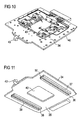
- FIG. 10 shows a perspective illustration of a substrate carrier
- FIG. 11 shows a perspective illustration of the underside of the substrate carrier
- FIG. 12 shows a perspective illustration of a carriage with inserted substrate carrier
- FIG. 13 shows an outline perspective illustration of a chuck with second holding elements.
- a test apparatus 1 has a chuck 2 which is provided with a bearing surface 3 for a semiconductor wafer 4 as test substrate.
- the chuck 2 is provided with a chuck drive 5 , by means of which the chuck 2 can be displaced in a working area 6 .
- the working area 6 of the chuck 2 is surrounded by a housing 7 which, on its operator side 8 , has an opening 9 which can be closed off with a flap 10 .
- a carriage 11 which can be displaced between a first position 12 close to the chuck, in which the chuck 2 is located in a position inside the working area 6 , and the second receiving position 13 through the opening 9 in the housing 7 , is arranged at the chuck 2 .
- the carriage 11 comprises two telescopic rails 14 which are arranged laterally adjacent to the chuck 2 and are arranged below a plane in which the bearing surface 3 lies.
- the carriage 11 also has a carriage drive 15 , which is connected to the chuck drive 5 .
- the carriage 11 is provided with a receiving member 16 .
- the receiving member 16 is provided with a forceps holder 17 for receiving forceps 18 which hold the semiconductor wafer 4 .
- Three lifting pins 19 are arranged in the chuck 2 and can move perpendicularly with respect to the bearing surface.
- the forceps holder 17 is provided with a vertical support 20 , with the result that the forceps holder 17 is at a vertical distance 21 from the carriage 11 , and therefore the semiconductor wafer 4 lies a short distance above the tips of the lifting pins 19 .
- the forceps 18 are provided with a vacuum suction surface 22 , which engages beneath the underside of the semiconductor wafer 4 .
- Vacuum grooves 23 to which a vacuum can be applied, are formed into the vacuum suction surface 22 .
- a three-way valve 25 is arranged in a shank 24 of the forceps 18 . This valve is connected, by means of a vacuum port 26 , to a vacuum source, and at the other sides is connected to the vacuum grooves 23 and to the open atmosphere. By switching the valve 25 , it is possible for the vacuum suction surface 19 to suck the semiconductor wafer 4 onto it or to apply air to the vacuum suction surface 22 .
- the forceps 18 may also be provided with a turntable in order also to align the angular position of the semiconductor wafer 4 .
- the turntable is mounted in an air pocket bearing to which a vacuum can also be applied, so that a clamping action is produced. After the aligning operation has ended, this turntable can be fixed in place using a vacuum.
- the length of the shank 24 is such that the three-way valve 25 , in the position in which the carriage 111 is located in the first position close to the chuck, is accessible from the outside, i.e. from outside the housing 7 .
- the forceps 18 After the forceps 18 have been detached, they can be removed from the semiconductor wafer 4 , since the extended lifting pins 19 set a distance between the bearing surface 3 and the underside of the semiconductor wafer 4 . The forceps 18 can then move freely within this space and can be pulled out. This once again is effected by means of the carriage 11 , to the holder 16 of which the forceps 18 are still secured via the forceps holder 17 . The carriage 11 therefore moves the forceps 18 back to the receiving position 13 , where the operator 27 releases the forceps 18 from the forceps holder 17 . After the carriage 11 has been moved back into its first position 12 close to the chuck, the flap 10 is closed.
- the chuck 2 comprises a chuck body 28 with a chuck surface 29 and a chuck plate 30 resting on the chuck surface 29 .
- the chuck plate 30 is provided with the bearing surface 3 . It can be detached from the chuck body 28 .
- the chuck plate 30 has three lugs 31 projecting above the chuck surface 29 .
- the lugs 31 are screwed to the cylindrical chuck plate 30 , including an angle of 120° with the angle point at the center of the chuck plate 30 .
- the receiving member 16 comprises a plate 32 in which an opening 33 with an opening surface area has been formed.
- the opening surface area of the opening 33 is sufficiently similar to the chuck surface area 29 for the holder 16 , in the position close to the chuck, to engage around the chuck body 28 in the region of the chuck surface 29 without contact, at a distance which is smaller than the extent to which the lugs 31 project above the chuck surface 29 .
- FIGS. 8 to 13 illustrate an exemplary embodiment with a carriage 11 which can be pushed in.
- a substrate carrier 34 as illustrated in FIG. 11 , has, on its underside 35 , the first holding member in the form of a guide groove 36 which has been formed into a guiding profiled section 37 .
- the guiding profiled section 37 is provided with a groove edge 39 which reduces the guide groove width to a slot 38 in the edge region of the guide groove 36 .
- a substrate opening 40 which is used to receive components which are to be tested and are not shown in more detail, in each case one guiding profiled section 37 of this type is connected to the underside 35 of the substrate carrier 34 .
- Two holding members in the form of holding pins 41 which are illustrated in FIG. 13 , engage releasably into the guide grooves 36 .
- These holding pins 41 are connected to the chuck 2 in such a way that they can move only in the vertical direction and are subject to downwardly directed spring load.
- the holding pins 41 are pressed onto the chuck drive 4 , while in the upper position they are released from the chuck drive 5 .
- the carriage 11 can be pushed in from the outside from the receiving position 13 .
- the substrate carrier 34 has a third holding member in the form of a first pawl 43 .
- a second pawl 45 which is connected to the carriage 11 and can be moved from the outside by the operator 27 via a pull lever 44 , engages as a fourth holding member into this first pawl 43 .
- the second pawl 45 can be released from the first pawl 43 by actuation of the pull lever 44 .
- the substrate carrier 34 is provided, on its right-hand and left-hand sides as seen from the receiving position 13 , with longitudinal guides 46 , which run parallel to the straight line of movement 47 between second receiving position 13 and first position 12 close to the chuck.
- the carriage 11 has two inner guide rails 48 , within which the longitudinal guides 46 can be pushed in.
- Outer guide rails 49 into which the carriage 11 can be pushed, are provided in a fixed position relative to the second receiving position 13 .
- the test substrate can be prepared outside the test apparatus 1 , by the substrate carrier 34 being mounted, for example, with a plurality of components which are to be tested.
- the mounted substrate carrier 34 is then pushed, by means of its longitudinal guides 46 , into the inner guide rails 48 of the substrate carrier 34 .
- the second pawl 45 latches into the first pawl 43 , preventing the substrate carrier 34 from dropping out of the carriage 11 .
- the carriage 11 together with the substrate carrier 34 , is pushed on the outer guide rails 49 from the receiving position 13 to the position 12 close to the chuck.
- the substrate carrier 34 is also blocked toward the top. This then allows a non-positive connection to be produced between the bearing surface 3 of the chuck 2 and the underside 35 of the substrate carrier 34 , resulting in good thermally conducting contact.
- the chuck 2 moves upward when the substrate carrier 34 has been pushed on and accordingly presses against the substrate carrier 34 . Since the latter is held at the top by means of the groove edge 39 and correspondingly by means of the head 42 at the bottom, a compressive force is produced.
- the holding pins 41 are pulled under spring load into their lower position.
- the base surfaces 50 of the guide grooves 36 are supported on the top points 51 of the heads 42 , with the guiding longitudinal sides 46 becoming detached from the inner guide rails 48 .
- the second pawl 45 is released from the first pawl 43 by means of the pull lever 44 .
- the carriage 11 can be pulled completely back out, with the carriage 11 once again sliding in the outer guide rails 49 until it can be removed again at the receiving position 13 .
- the chuck 2 moves back downward, with the result that the substrate carrier 34 is then resting on the holding pins 41 only under its own weight.
- the carriage 11 is now pushed back through the flap 10 .
- the substrate carrier slides into the inner guide rails 48 of the carriage 11 .
- the second pawl 45 then latched into the first pawl 43 .
- the carriage 11 which has been provided with the substrate carrier 34 can then be moved back out of the housing and the test apparatus 1 is ready for the next testing operation.
Abstract
Description
Claims (20)
Applications Claiming Priority (4)
| Application Number | Priority Date | Filing Date | Title |
|---|---|---|---|
| DE2002146282 DE10246282B4 (en) | 2002-10-02 | 2002-10-02 | Prober for testing substrates at low temperatures |
| DE2002146232 DE10246232B4 (en) | 2002-10-02 | 2002-10-02 | Test device with loading device |
| DE10246282.8 | 2002-10-02 | ||
| DE10246232.1 | 2002-10-02 |
Publications (2)
| Publication Number | Publication Date |
|---|---|
| US20040108847A1 US20040108847A1 (en) | 2004-06-10 |
| US7038441B2 true US7038441B2 (en) | 2006-05-02 |
Family
ID=32070711
Family Applications (2)
| Application Number | Title | Priority Date | Filing Date |
|---|---|---|---|
| US10/677,178 Expired - Fee Related US7046025B2 (en) | 2002-10-02 | 2003-10-02 | Test apparatus for testing substrates at low temperatures |
| US10/677,524 Active 2024-05-09 US7038441B2 (en) | 2002-10-02 | 2003-10-02 | Test apparatus with loading device |
Family Applications Before (1)
| Application Number | Title | Priority Date | Filing Date |
|---|---|---|---|
| US10/677,178 Expired - Fee Related US7046025B2 (en) | 2002-10-02 | 2003-10-02 | Test apparatus for testing substrates at low temperatures |
Country Status (1)
| Country | Link |
|---|---|
| US (2) | US7046025B2 (en) |
Cited By (3)
| Publication number | Priority date | Publication date | Assignee | Title |
|---|---|---|---|---|
| US20070132474A1 (en) * | 2005-08-16 | 2007-06-14 | Professional Testing (Emi), Inc. | Automated platform for electronic apparatus environmental testing & method of use |
| US20080116918A1 (en) * | 2006-11-17 | 2008-05-22 | Suss Microtec Test Systems Gmbh | Probe station to testing semiconductor substrates and comprising emi shielding |
| US20090315581A1 (en) * | 2008-06-24 | 2009-12-24 | Suss Microtec Test Systems Gmbh | Chuck for supporting and retaining a test substrate and a calibration substrate |
Families Citing this family (41)
| Publication number | Priority date | Publication date | Assignee | Title |
|---|---|---|---|---|
| US5914613A (en) | 1996-08-08 | 1999-06-22 | Cascade Microtech, Inc. | Membrane probing system with local contact scrub |
| US6256882B1 (en) | 1998-07-14 | 2001-07-10 | Cascade Microtech, Inc. | Membrane probing system |
| US6914423B2 (en) | 2000-09-05 | 2005-07-05 | Cascade Microtech, Inc. | Probe station |
| US6965226B2 (en) | 2000-09-05 | 2005-11-15 | Cascade Microtech, Inc. | Chuck for holding a device under test |
| DE10143173A1 (en) | 2000-12-04 | 2002-06-06 | Cascade Microtech Inc | Wafer probe has contact finger array with impedance matching network suitable for wide band |
| AU2002327490A1 (en) | 2001-08-21 | 2003-06-30 | Cascade Microtech, Inc. | Membrane probing system |
| DE10216786C5 (en) * | 2002-04-15 | 2009-10-15 | Ers Electronic Gmbh | Method and apparatus for conditioning semiconductor wafers and / or hybrids |
| US7492172B2 (en) | 2003-05-23 | 2009-02-17 | Cascade Microtech, Inc. | Chuck for holding a device under test |
| US7057404B2 (en) | 2003-05-23 | 2006-06-06 | Sharp Laboratories Of America, Inc. | Shielded probe for testing a device under test |
| US7250626B2 (en) | 2003-10-22 | 2007-07-31 | Cascade Microtech, Inc. | Probe testing structure |
| KR20060126700A (en) | 2003-12-24 | 2006-12-08 | 캐스케이드 마이크로테크 인코포레이티드 | Active wafer probe |
| US7187188B2 (en) | 2003-12-24 | 2007-03-06 | Cascade Microtech, Inc. | Chuck with integrated wafer support |
| US6833717B1 (en) * | 2004-02-12 | 2004-12-21 | Applied Materials, Inc. | Electron beam test system with integrated substrate transfer module |
| EP1628132B1 (en) | 2004-08-17 | 2015-01-07 | Sensirion Holding AG | Method and device for calibrating sensors |
| KR20070058522A (en) | 2004-09-13 | 2007-06-08 | 캐스케이드 마이크로테크 인코포레이티드 | Double sided probing structures |
| US7535247B2 (en) | 2005-01-31 | 2009-05-19 | Cascade Microtech, Inc. | Interface for testing semiconductors |
| US7656172B2 (en) | 2005-01-31 | 2010-02-02 | Cascade Microtech, Inc. | System for testing semiconductors |
| JP2007042911A (en) * | 2005-08-04 | 2007-02-15 | Sumitomo Electric Ind Ltd | Wafer holder and wafer prober mounted with the same |
| JP2007165390A (en) * | 2005-12-09 | 2007-06-28 | Fujitsu Ltd | Inspection apparatus and method therefor |
| US7723999B2 (en) | 2006-06-12 | 2010-05-25 | Cascade Microtech, Inc. | Calibration structures for differential signal probing |
| US7764072B2 (en) | 2006-06-12 | 2010-07-27 | Cascade Microtech, Inc. | Differential signal probing system |
| US7403028B2 (en) | 2006-06-12 | 2008-07-22 | Cascade Microtech, Inc. | Test structure and probe for differential signals |
| DE102006038457B4 (en) * | 2006-08-16 | 2014-05-22 | Cascade Microtech, Inc. | Method and device for tempering electronic components |
| US7876114B2 (en) | 2007-08-08 | 2011-01-25 | Cascade Microtech, Inc. | Differential waveguide probe |
| DE112008002615B4 (en) * | 2007-10-10 | 2015-02-19 | Cascade Microtech, Inc. | Method for testing a test substrate under defined thermal conditions and thermally conditionable prober |
| US8424594B2 (en) * | 2007-12-10 | 2013-04-23 | Presto Engineering, Inc. | Apparatus for thermal control in the analysis of electronic devices |
| TW201011848A (en) * | 2008-09-04 | 2010-03-16 | Star Techn Inc | Apparatus for testing integrated circuits |
| DE102008048081B4 (en) * | 2008-09-19 | 2015-06-18 | Cascade Microtech, Inc. | Method for testing electronic components of a repeating structure under defined thermal conditions |
| US7888957B2 (en) | 2008-10-06 | 2011-02-15 | Cascade Microtech, Inc. | Probing apparatus with impedance optimized interface |
| WO2010059247A2 (en) | 2008-11-21 | 2010-05-27 | Cascade Microtech, Inc. | Replaceable coupon for a probing apparatus |
| US8319503B2 (en) | 2008-11-24 | 2012-11-27 | Cascade Microtech, Inc. | Test apparatus for measuring a characteristic of a device under test |
| EP2259027B1 (en) * | 2009-06-04 | 2012-12-05 | Sensirion AG | Method and apparatus for processing individual sensor devices |
| US8613288B2 (en) * | 2009-12-18 | 2013-12-24 | Lam Research Ag | High temperature chuck and method of using same |
| US8608146B2 (en) * | 2009-12-18 | 2013-12-17 | Lam Research Ag | Reinforced pin for being used in a pin chuck, and a pin chuck using such reinforced pin |
| JP5459907B2 (en) * | 2010-01-27 | 2014-04-02 | 東京エレクトロン株式会社 | Evaluation apparatus for substrate mounting apparatus, evaluation method therefor, and evaluation substrate used therefor |
| DE202010003817U1 (en) * | 2010-03-18 | 2010-07-29 | Cascade Microtech Dresden Gmbh | Prober for on-water measurements under EMI shielding |
| EP2418503B1 (en) | 2010-07-14 | 2013-07-03 | Sensirion AG | Needle head |
| WO2016148855A1 (en) | 2015-03-19 | 2016-09-22 | Applied Materials, Inc. | Method and apparatus for reducing radiation induced change in semiconductor structures |
| EP3734301A1 (en) * | 2019-05-03 | 2020-11-04 | Afore Oy | Cryogenic wafer prober with movable thermal radiation shield |
| EP4062445A4 (en) | 2019-11-19 | 2023-12-20 | High Precision Devices Inc. | Cryogenic wafer testing system |
| CN111257717A (en) * | 2020-03-03 | 2020-06-09 | 李鑫 | Detection device for PIN diode |
Citations (6)
| Publication number | Priority date | Publication date | Assignee | Title |
|---|---|---|---|---|
| US5077523A (en) * | 1989-11-03 | 1991-12-31 | John H. Blanz Company, Inc. | Cryogenic probe station having movable chuck accomodating variable thickness probe cards |
| US5410259A (en) * | 1992-06-01 | 1995-04-25 | Tokyo Electron Yamanashi Limited | Probing device setting a probe card parallel |
| US5936416A (en) * | 1996-05-17 | 1999-08-10 | Tokyo Electron Limited | Probe inspection apparatus |
| US6420864B1 (en) * | 2000-04-13 | 2002-07-16 | Nanophotonics Ag | Modular substrate measurement system |
| US6545458B2 (en) * | 2000-03-30 | 2003-04-08 | Nagase Sangyo Kabushiki Kaisha | Low-temperature test equipment |
| US6762616B2 (en) * | 2001-12-13 | 2004-07-13 | Tokyo Electron Limited | Probe system |
Family Cites Families (12)
| Publication number | Priority date | Publication date | Assignee | Title |
|---|---|---|---|---|
| JPS6090684U (en) * | 1983-11-28 | 1985-06-21 | 株式会社椿本チエイン | Power supply device for energized load test equipment |
| US5266889A (en) * | 1992-05-29 | 1993-11-30 | Cascade Microtech, Inc. | Wafer probe station with integrated environment control enclosure |
| US5775416A (en) * | 1995-11-17 | 1998-07-07 | Cvc Products, Inc. | Temperature controlled chuck for vacuum processing |
| JP3388271B2 (en) * | 1997-05-19 | 2003-03-17 | 東京エレクトロン株式会社 | Probe device |
| US6222990B1 (en) * | 1997-12-03 | 2001-04-24 | Steag Rtp Systems | Heating element for heating the edges of wafers in thermal processing chambers |
| US5930456A (en) * | 1998-05-14 | 1999-07-27 | Ag Associates | Heating device for semiconductor wafers |
| US6198299B1 (en) * | 1998-08-27 | 2001-03-06 | The Micromanipulator Company, Inc. | High Resolution analytical probe station |
| JP2000183120A (en) * | 1998-12-17 | 2000-06-30 | Mitsubishi Electric Corp | Prober device and electrical evaluation method for semiconductor device |
| US6771895B2 (en) * | 1999-01-06 | 2004-08-03 | Mattson Technology, Inc. | Heating device for heating semiconductor wafers in thermal processing chambers |
| US6344750B1 (en) * | 1999-01-08 | 2002-02-05 | Schlumberger Technologies, Inc. | Voltage contrast method for semiconductor inspection using low voltage particle beam |
| US6538440B2 (en) * | 2001-06-20 | 2003-03-25 | Ge Medical Systems Global Technology Co., Llc | Non-conductive long wave thermal radiation shield |
| US6735378B1 (en) * | 2003-05-29 | 2004-05-11 | Axcelis Technologies, Inc. | Pressure controlled heat source and method for using such for RTP |
-
2003
- 2003-10-02 US US10/677,178 patent/US7046025B2/en not_active Expired - Fee Related
- 2003-10-02 US US10/677,524 patent/US7038441B2/en active Active
Patent Citations (6)
| Publication number | Priority date | Publication date | Assignee | Title |
|---|---|---|---|---|
| US5077523A (en) * | 1989-11-03 | 1991-12-31 | John H. Blanz Company, Inc. | Cryogenic probe station having movable chuck accomodating variable thickness probe cards |
| US5410259A (en) * | 1992-06-01 | 1995-04-25 | Tokyo Electron Yamanashi Limited | Probing device setting a probe card parallel |
| US5936416A (en) * | 1996-05-17 | 1999-08-10 | Tokyo Electron Limited | Probe inspection apparatus |
| US6545458B2 (en) * | 2000-03-30 | 2003-04-08 | Nagase Sangyo Kabushiki Kaisha | Low-temperature test equipment |
| US6420864B1 (en) * | 2000-04-13 | 2002-07-16 | Nanophotonics Ag | Modular substrate measurement system |
| US6762616B2 (en) * | 2001-12-13 | 2004-07-13 | Tokyo Electron Limited | Probe system |
Cited By (7)
| Publication number | Priority date | Publication date | Assignee | Title |
|---|---|---|---|---|
| US20070132474A1 (en) * | 2005-08-16 | 2007-06-14 | Professional Testing (Emi), Inc. | Automated platform for electronic apparatus environmental testing & method of use |
| US7372252B2 (en) * | 2005-08-16 | 2008-05-13 | Professional Testing (Emi), Inc. | Automated platform for electronic apparatus environmental testing & method of use |
| US20080116918A1 (en) * | 2006-11-17 | 2008-05-22 | Suss Microtec Test Systems Gmbh | Probe station to testing semiconductor substrates and comprising emi shielding |
| US8278951B2 (en) * | 2006-11-17 | 2012-10-02 | Cascade Microtech, Inc. | Probe station for testing semiconductor substrates and comprising EMI shielding |
| US20090315581A1 (en) * | 2008-06-24 | 2009-12-24 | Suss Microtec Test Systems Gmbh | Chuck for supporting and retaining a test substrate and a calibration substrate |
| US7999563B2 (en) * | 2008-06-24 | 2011-08-16 | Cascade Microtech, Inc. | Chuck for supporting and retaining a test substrate and a calibration substrate |
| US8680879B2 (en) | 2008-06-24 | 2014-03-25 | Cascade Microtech, Inc. | Chuck for supporting and retaining a test substrate and a calibration substrate |
Also Published As
| Publication number | Publication date |
|---|---|
| US20040108847A1 (en) | 2004-06-10 |
| US7046025B2 (en) | 2006-05-16 |
| US20040070415A1 (en) | 2004-04-15 |
Similar Documents
| Publication | Publication Date | Title |
|---|---|---|
| US7038441B2 (en) | Test apparatus with loading device | |
| JP4123408B2 (en) | Probe card changer | |
| KR100503516B1 (en) | Probe card transfer mechanism | |
| KR100986396B1 (en) | Substrate attracting device and substrate transfer apparatus | |
| US9121901B2 (en) | Semiconductor wafer test apparatus | |
| JP6961907B2 (en) | Prober | |
| US20080240891A1 (en) | Transfer and inspection devices of object to be inspected | |
| JP5517344B2 (en) | Probe card transport mechanism, probe card transport method, and probe apparatus | |
| US20150123685A1 (en) | Module for exchanging an interface unit in a testing system for testing semiconductor components and testing system comprising such a module | |
| KR101696682B1 (en) | Electronic device handling apparatus and electronic device testing apparatus | |
| JP3567803B2 (en) | IC device test equipment | |
| JP7324992B2 (en) | prober | |
| KR101839214B1 (en) | Probe card transferring apparatus, probe card transferring method and probe apparatus | |
| KR100911337B1 (en) | Carrier board transferring apparatus for test handler and test handler | |
| KR20190103957A (en) | Inspection system | |
| US8262993B2 (en) | Slidable autosampler tray | |
| TW201016574A (en) | Position alignment device for cassette of exposure equipment | |
| US6471462B1 (en) | Carrier handling apparatus of an IC module handler | |
| US10782341B2 (en) | Semiconductor device handler with a floating clamp | |
| JP3339608B2 (en) | IC test equipment | |
| KR102304704B1 (en) | Aligner Device And Alignment Method | |
| JP2002261144A (en) | Method and device for delivering substrate | |
| JP7218495B2 (en) | prober | |
| JP4163477B2 (en) | Support device for substrate to be inspected | |
| JP6076788B2 (en) | Substrate fixing device for substrate to be inspected and method for fixing the substrate |
Legal Events
| Date | Code | Title | Description |
|---|---|---|---|
| AS | Assignment |
Owner name: SUSS MICROTEC TESTSYSTEMS (GMBH), GERMANY Free format text: ASSIGNMENT OF ASSIGNORS INTEREST;ASSIGNORS:STOLL, KARSTEN;KREIBIG, STEFAN;WACHTVEITL, ALF;AND OTHERS;REEL/FRAME:014969/0075;SIGNING DATES FROM 20040112 TO 20040115 |
|
| STCF | Information on status: patent grant |
Free format text: PATENTED CASE |
|
| FPAY | Fee payment |
Year of fee payment: 4 |
|
| SULP | Surcharge for late payment | ||
| AS | Assignment |
Owner name: CASCADE MICROTECH, INC., OREGON Free format text: MERGER;ASSIGNOR:SUSS MICROTEC TEST SYSTEMS GMBH;REEL/FRAME:026246/0706 Effective date: 20100127 |
|
| FEPP | Fee payment procedure |
Free format text: PAT HOLDER CLAIMS SMALL ENTITY STATUS, ENTITY STATUS SET TO SMALL (ORIGINAL EVENT CODE: LTOS); ENTITY STATUS OF PATENT OWNER: LARGE ENTITY |
|
| REMI | Maintenance fee reminder mailed | ||
| FPAY | Fee payment |
Year of fee payment: 8 |
|
| SULP | Surcharge for late payment |
Year of fee payment: 7 |
|
| FEPP | Fee payment procedure |
Free format text: PAT HOLDER NO LONGER CLAIMS SMALL ENTITY STATUS, ENTITY STATUS SET TO UNDISCOUNTED (ORIGINAL EVENT CODE: STOL); ENTITY STATUS OF PATENT OWNER: LARGE ENTITY |
|
| AS | Assignment |
Owner name: HSBC BANK USA, NATIONAL ASSOCIATION, CALIFORNIA Free format text: SECURITY INTEREST IN UNITED STATES PATENTS AND TRADEMARKS;ASSIGNORS:FORMFACTOR, INC.;ASTRIA SEMICONDUCTOR HOLDINGS, INC.;CASCADE MICROTECH, INC.;AND OTHERS;REEL/FRAME:039184/0280 Effective date: 20160624 |
|
| MAFP | Maintenance fee payment |
Free format text: PAYMENT OF MAINTENANCE FEE, 12TH YEAR, LARGE ENTITY (ORIGINAL EVENT CODE: M1553) Year of fee payment: 12 |
|
| AS | Assignment |
Owner name: FORMFACTOR BEAVERTON, INC., OREGON Free format text: CHANGE OF NAME;ASSIGNOR:CASCADE MICROTECH, INC.;REEL/FRAME:046573/0664 Effective date: 20180514 |
|
| AS | Assignment |
Owner name: FORMFACTOR, INC., CALIFORNIA Free format text: ASSIGNMENT OF ASSIGNORS INTEREST;ASSIGNOR:FORMFACTOR BEAVERTON, INC.;REEL/FRAME:057393/0609 Effective date: 20210826 |