US7040349B2 - Piezo-electric actuated multi-valve manifold - Google Patents
Piezo-electric actuated multi-valve manifold Download PDFInfo
- Publication number
- US7040349B2 US7040349B2 US10/817,512 US81751204A US7040349B2 US 7040349 B2 US7040349 B2 US 7040349B2 US 81751204 A US81751204 A US 81751204A US 7040349 B2 US7040349 B2 US 7040349B2
- Authority
- US
- United States
- Prior art keywords
- rigid
- arm portions
- folded
- pivotable
- valve
- Prior art date
- Legal status (The legal status is an assumption and is not a legal conclusion. Google has not performed a legal analysis and makes no representation as to the accuracy of the status listed.)
- Expired - Fee Related, expires
Links
- 239000012530 fluid Substances 0.000 claims abstract description 31
- 230000004044 response Effects 0.000 claims abstract description 18
- 230000004913 activation Effects 0.000 claims abstract description 14
- 238000007789 sealing Methods 0.000 claims description 4
- 230000007423 decrease Effects 0.000 description 5
- 238000002156 mixing Methods 0.000 description 5
- 230000008901 benefit Effects 0.000 description 4
- 230000000295 complement effect Effects 0.000 description 4
- 238000010276 construction Methods 0.000 description 4
- 239000000463 material Substances 0.000 description 4
- 238000006073 displacement reaction Methods 0.000 description 3
- 238000004448 titration Methods 0.000 description 3
- 239000002131 composite material Substances 0.000 description 2
- 230000003247 decreasing effect Effects 0.000 description 2
- 238000010586 diagram Methods 0.000 description 2
- 230000005672 electromagnetic field Effects 0.000 description 2
- 230000017525 heat dissipation Effects 0.000 description 2
- 239000007769 metal material Substances 0.000 description 2
- 238000000034 method Methods 0.000 description 2
- 238000005497 microtitration Methods 0.000 description 2
- 238000012986 modification Methods 0.000 description 2
- 230000004048 modification Effects 0.000 description 2
- 230000004075 alteration Effects 0.000 description 1
- 239000003153 chemical reaction reagent Substances 0.000 description 1
- 230000002860 competitive effect Effects 0.000 description 1
- 238000001816 cooling Methods 0.000 description 1
- 230000007613 environmental effect Effects 0.000 description 1
- 230000020169 heat generation Effects 0.000 description 1
- 239000002184 metal Substances 0.000 description 1
- 229910001092 metal group alloy Inorganic materials 0.000 description 1
- 238000004806 packaging method and process Methods 0.000 description 1
- 238000009428 plumbing Methods 0.000 description 1
- 239000012255 powdered metal Substances 0.000 description 1
- 239000010935 stainless steel Substances 0.000 description 1
- 229910001220 stainless steel Inorganic materials 0.000 description 1
- 230000000638 stimulation Effects 0.000 description 1
Images


Classifications
-
- F—MECHANICAL ENGINEERING; LIGHTING; HEATING; WEAPONS; BLASTING
- F16—ENGINEERING ELEMENTS AND UNITS; GENERAL MEASURES FOR PRODUCING AND MAINTAINING EFFECTIVE FUNCTIONING OF MACHINES OR INSTALLATIONS; THERMAL INSULATION IN GENERAL
- F16K—VALVES; TAPS; COCKS; ACTUATING-FLOATS; DEVICES FOR VENTING OR AERATING
- F16K27/00—Construction of housing; Use of materials therefor
- F16K27/003—Housing formed from a plurality of the same valve elements
-
- F—MECHANICAL ENGINEERING; LIGHTING; HEATING; WEAPONS; BLASTING
- F16—ENGINEERING ELEMENTS AND UNITS; GENERAL MEASURES FOR PRODUCING AND MAINTAINING EFFECTIVE FUNCTIONING OF MACHINES OR INSTALLATIONS; THERMAL INSULATION IN GENERAL
- F16K—VALVES; TAPS; COCKS; ACTUATING-FLOATS; DEVICES FOR VENTING OR AERATING
- F16K31/00—Actuating devices; Operating means; Releasing devices
- F16K31/004—Actuating devices; Operating means; Releasing devices actuated by piezoelectric means
- F16K31/005—Piezo-electric benders
- F16K31/006—Piezo-electric benders having a free end
-
- Y—GENERAL TAGGING OF NEW TECHNOLOGICAL DEVELOPMENTS; GENERAL TAGGING OF CROSS-SECTIONAL TECHNOLOGIES SPANNING OVER SEVERAL SECTIONS OF THE IPC; TECHNICAL SUBJECTS COVERED BY FORMER USPC CROSS-REFERENCE ART COLLECTIONS [XRACs] AND DIGESTS
- Y10—TECHNICAL SUBJECTS COVERED BY FORMER USPC
- Y10T—TECHNICAL SUBJECTS COVERED BY FORMER US CLASSIFICATION
- Y10T137/00—Fluid handling
- Y10T137/8593—Systems
- Y10T137/877—With flow control means for branched passages
- Y10T137/87877—Single inlet with multiple distinctly valved outlets
-
- Y—GENERAL TAGGING OF NEW TECHNOLOGICAL DEVELOPMENTS; GENERAL TAGGING OF CROSS-SECTIONAL TECHNOLOGIES SPANNING OVER SEVERAL SECTIONS OF THE IPC; TECHNICAL SUBJECTS COVERED BY FORMER USPC CROSS-REFERENCE ART COLLECTIONS [XRACs] AND DIGESTS
- Y10—TECHNICAL SUBJECTS COVERED BY FORMER USPC
- Y10T—TECHNICAL SUBJECTS COVERED BY FORMER US CLASSIFICATION
- Y10T137/00—Fluid handling
- Y10T137/8593—Systems
- Y10T137/877—With flow control means for branched passages
- Y10T137/87885—Sectional block structure
Definitions
- the present invention relates to at least one piezo-electric actuated valve capable of two-way or three-way operation for on/off or proportional control of fluid passing between at least one inlet port and at least one outlet port of a fluid passageway.
- solenoid operated valves typically are available in sizes down to a minimum 6 mm in diameter. Although valves smaller than 4.5 mm exist, the valves are much smaller, and are based on alternate construction and/or actuation techniques such as MEMS. In general, smaller solenoid based valves do not exist, because as the solenoid decreases in size, the work capability of the solenoid is reduced to the point where the solenoid is incapable of providing operation of the valve for the desired valve pressures and flow rates. It would be desirable in the present invention to provide an electrically actuated valve capable of being sized to 4.5 mm or less.
- Typical commercially available solenoid valves respond with times in a range from 5 ms to 20 ms. Higher speed for the solenoids can be achieved, but generally require special electronic control such as overexcitation or special coil construction. It would be desirable to provide an electrically actuated, direct acting valve capable of response times in a range less than 5 ms, and preferably approximately 1 ms.
- piezo valves that do have the desired level of pressure and flow capability typically reach the desired levels when acting as a pilot valve for a larger valve, where the larger valve provides the desired level of pressure and flow capability.
- piezo valves can reach the desired performance levels but require greater width. It would be desirable in the present invention to provide a direct acting electrically actuated valve with high pressure and high flow capabilities without acting as a pilot valve for a larger valve and with a narrow width.
- proportional valves can be, for example, approximately 22.2 mm in diameter and 39.6 mm tall.
- the version of such a commercially available proportional valve with an orifice size of ⁇ 1.5 mm can flow up to fourteen standard liters per minute (slpm) at the maximum pressure of twenty-five pounds per square inch (psi). Further, the maximum rated pressure at any flow for the commercially available proportional valve is 100 psi. It would be desirable to provide an electrically actuated proportional valve which can operate at over 120 psi with a 1.5 mm equivalent orifice, and to provide an electrically actuated proportional valve which at 80 psi can flow up to approximately 50 slpm.
- An apparatus controls the flow of a fluid from at least one inlet port to at least one outlet port through a fluid flow passage in response to an electrical activation.
- the apparatus can include a support having a rigid, non-flexible portion, at least one pivotable relatively rigid, non-flexible, folded-back arm portion extending from the rigid portion, at least one surface associated with the at least one folded-back arm portion for movement relative to the support, and a rigid, non-flexible force transfer member operably positioned for driving the at least one pivotable folded-back arm portion in rotational movement.
- An electrically operated actuator operably engages between the rigid, non-flexible portion and the force transfer member to drive the force transfer member relative to the rigid, non-flexible portion to pivot the at least one pivotable folded-back arm portion in response to an electrical activation of the actuator wherein the work produced by the rotational movement of the at least one pivotable folded-back arm portion can be greater than 60% of the work produced by the electrically operated actuator.
- a manifold includes a fluid passage communicating with at least one valve seat and operably engageable with respect to at least one corresponding valve body for movement between a closed position in sealing engagement with the valve seat and an opened position spaced from the valve seat, wherein at least one of the valve seat and valve body is operably movable with respect to the other by the electrically operated actuator through the support in response to an electrical activation.
- the multi-valve manifold according to the present invention can house and provide fluid connections for multiple piezo actuated, direct acting valves.
- the current design of the valves is three-way on-off. These valves can be used for various applications including, by way of example and not limitation, mixing and diverting.
- the manifold provides a common inlet port, a common exhaust port, and an outlet port unique to each valve. It also provides a single point for electrical connection and in some configurations the manifold will also house the system power supply and valve control.
- This same three-way valve configuration can be operated in a proportional mode for mixing or blending applications. In such applications, the common exhaust port, described above, would be used as a second common inlet port. Alteration of the flow can enable use for diverting applications.
- check valves can be incorporated to prevent undesirable flow.
- valve spacing is set at 4.5 mm. This tight spacing allows, for example, the valve to provide direct dispensing of analytical fluids. Such fluids can be transferred into titration wells that are currently spaced 4.5 mm apart in typical titration trays using, for example, a nozzle directly attached to the outlet ports of the manifold or minimal interface tubing from the valves to the wells. This can improve dispensing accuracy, save reagent volumes and improve dispensing times. Typical existing valve manifolds use 10 mm spacing, thus requiring complex valve mounting geometries and extensive tubing or manifolding to transfer the fluid being dispensed from the valve.
- the present invention provides for nozzles attached to the manifold on 4.5 mm pitch and in line with the valves located at 4.5 mm spacing from one another mounted on the manifold, i.e. the valve is inline and very close so that there is minimal “dead volume” from the valve to the dispensing orifice or nozzle.
- valve of the present invention can, by way of example and not limitation, also be used very effectively to pilot much larger pneumatically actuated valves.
- valves In a two-way configuration the valves can operate as proportional fluid controls. This level of control is believed to be unique in such small packaging. Further, the flow rates of valves according to the present invention would substantially exceed the performance of known comparable valves.
- FIG. 1 is an exploded view of a multi-valve manifold according to the present invention
- FIG. 2 is a schematic diagram illustrating two-way operation of a multi-valve manifold according to the present invention
- FIG. 3 is a schematic diagram illustrating three-way operation of a multi-valve manifold according to the present invention
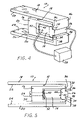
- FIG. 4 is a perspective view of an actuator assembly for moving at least one folded-back arm having at least one surface in response to an electrical activation, the actuator assembly having a support member and an electrical actuator according to the present invention
- FIG. 5 is a side view of the actuator assembly of FIG. 4 with the electrical actuator deactivated
- FIG. 6 is an exaggerated side view of the actuator assembly of FIG. 4 with the electrical actuator fully activated
- FIG. 7 is a side view of the actuator assembly with mechanically fastened pivotable relatively rigid, non-flexible arm portions connected to the rigid, non-flexible portion of the support and extending outwardly from a location of a living hinge.
- the present invention includes a multi-valve manifold 100 .
- Each valve 102 in the manifold 100 can be, by way of example and not limitation, 4.2 millimeters (mm) wide by 31 mm tall by 46 mm long.
- the narrow width of the actuator/valve combinations according to the present invention allows the actuator/valve combinations to be located on the manifold at a center-to-center spacing, or pitch, of 4.5 mm apart from one another in order to provide an advantageous titration tray dispensing embodiment discussed in greater detail below.
- the 4.2 mm width is believed to be narrower than any other “meso-scale” electrically actuated valve, and therefore unique in the industry.
- the closest known commercially available solenoid operated valve is 6 mm in diameter. Although electrically actuated valves smaller than 4.5 mm exist, the valves are much smaller, and are based on alternate construction and/or actuation techniques. In general, smaller solenoid based valve does not exist, because as the solenoid decreases in size, the work capability of the solenoid is reduced to the point where the solenoid is incapable of providing operation of the valve for the desired valve pressures and flow rates.
- Minimal heat generation is also important, because it eliminates, or at least greatly reduces the requirement for cooling considerations.
- the heat generated and associated heat transfer to the fluid being metered is not only a function of the solenoid coil versus piezo, it is also related to the fact that the present invention is able to separate the fluid control portion of the valve from the heat generating, actuation portion.
- a solenoid based valve frequently the fluid passages are very close to the coil. As the size decreases, the relative proximity tends to increase. In some cases, the fluid passage of a solenoid based valve actually pass “through” a passage within the heat generating coil of the solenoid.
- the multi-valve manifold having fluid control portions separate from piezo actuator portions according to the present invention avoids this disadvantage of the solenoid based valve.
- valve spacing is 4.5 mm pitch (4.5 mm on center valve to valve) allows the valves to line up exactly with the well in a standard 384 well microtitration tray.
- MEMS micro electromechanical system
- the multi-valve manifold according to the present invention can include an eight-pack manifold which can be doubled up to provide a sixteen valve version in order to allow direct dispensing into a complete row of wells in a standard 384 microtitration tray.
- Each valve is capable of on/off operation and also proportional operation.
- the closest known commercially available solenoid actuated proportional valve is no smaller than 15 mm in diameter. The issue is not merely the raw power of the electromagnetic field as the coil decreases. The ability to control the operation of the valve in a predictable linear fashion is also much more difficult. Further, a proportional valve is continually operating, thus requiring greater heat dissipation/handling ability than a simple on/off valve.
- valves have the potential to respond to on/off operations faster than 1 millisecond (ms).
- Typical competitive solenoid valves respond in 5 ms to 20 ms. Higher speed for the solenoids can be achieved, but typically require special electronics such as overexcitation or use special coil construction.
- each valve can be pressure balanced. This allows the use of a comparatively smaller actuator while providing high flow and pressure capability.
- the recently announced Clippard EVP proportional valve is 22.2 mm in diameter and 39.6 mm tall.
- the version with an orifice sized comparable to the orifice in each valve of the present invention can flow fourteen standard liters per minute (slpm) at the maximum pressure of twenty-five pounds per square inch (psi). Further, the maximum rated pressure at any flow for the Clippard EVP proportional valve is 100 psi.
- each valve according to the present invention can operate at over 120 psi with the standard 1.5 mm equivalent orifice, and at 80 psi the valve according to the present invention can flow up to approximately 50 slpm.
- the combination of the pressure balanced fluid control valve with the piezo actuator according to the present invention provides the improved performance, i.e. pressure balancing reduces the work that the actuator must produce thereby allowing the use of smaller piezo actuators.
- the unique basic form factor of the piezo actuator according to the present invention i.e. narrow relative to the other dimensions, especially when compared to solenoids, enables the overall narrow form of the valves according to the present invention.
- control electronics located in the manifold “bottom” rather than merely an electrical interface; for either two-way or three-way operation; simplified valve mounting into the manifold so that additional screws are not needed; a manifold with valves in any quantity other than 8 valves, for example 2, 3, 4, 5, . . . 8, . . . 16, . . .
- a fluid inlet port located in alternate position, by way of example and not limitation, such as a “bottom” entry and located central to the valves to reduce the distance from the inlet to the furthest valve (manifold dead volume); for use of non-pressured balanced valve, which would offer less flow but can offer other benefits, by way of example and not limitation, such as longer life or simpler assembly; various size multi-valve manifolds since the valve width according to the present invention is potentially scalable to smaller sizes, by way of example and limitation, to approximately half the width of the valve discussed above (i.e.
- FIG. 4 is a perspective view of an actuator assembly 10 having a support 12 and an electrical actuator 14 in accordance with the present invention.
- the support 12 includes a rigid, non-flexible portion 16 , at least one pivotable relatively rigid, non-flexible arm portion, such as first and second pivotable arm portions 18 , 20 extending rearward from the rigid portion 16 , at least one opposing surface 22 , 24 on the at least one pivotable arm portion 18 , 20 for movement relative to to the rigid portion 16 , and a rigid, non-flexible force transfer member 26 operably connected with the at least one pivotable arm portion 18 , 20 .
- the support 12 is a unitary, integral, single-piece monolithic body.
- the electrical actuator 14 can be operably engaged between the rigid, non-flexible portion 16 and the rigid, non-flexible force transfer member 26 to drive the force transfer member 26 in linear motion away from the rigid, non-flexible portion 16 in response to electrical stimulation of the electrical actuator 14 .
- the rigid, non-flexible portions of the support 12 can provide transfer of motion from the electrical actuator 14 with a loss of work of less than 40%, preferably with a loss of work of less than 20%, and most preferably with a loss of work of less than 10%.
- the at least one pivotable relatively rigid non-flexible arm 18 , 20 is rigid and non-flexible in an environment with relatively limited temperature variations or in a temperature controlled environment. It should be recognized that the at least one pivotable arm 18 , 20 can include temperature compensation for improved on/off operation and/or proportional operation control over a wider range of environmental temperatures, if desired.
- the rigid non-flexible portion 16 can receive an adjustable support 54 with an adjustable seat 52 having a complementary surface to the end 42 of the actuator 14 .
- the complementary surface of the adjustable seat 52 can be flat or shaped in any manner to support the actuator 14 in a position suitable for driving the force transfer member 26 in response to an electrical actuation of the actuator 14 . Movement of the rigid, non-flexible force transfer member 26 pivots the at least one pivotable arm portion 18 , 20 about at least one living hinge 36 , 38 .
- At least one living hinge 36 , 38 extends between each rigid arm portion and a pivotal base portion 46 , 48 of each corresponding pivotable relatively rigid, non-flexible arm portion, and at least one living hinge 32 , 34 extends between the corresponding base portion 46 , 48 of the pivotable relatively rigid, non-flexible arm portions and the rigid force transfer member 26 .
- a controller 28 can be provided to operate the apparatus 10 .
- the controller can provide a charging voltage across the piezoelectric device to produce spatial displacement along a predetermined axis.
- the amount of electrical charge stored by the piezoelectric device is generally proportional to the amount of voltage applied across the piezoelectric device.
- varying the amount of voltage applied across the piezoelectric device can control the amount of spatial displacement along one predetermined axis.
- This spatial displacement is transferred and amplified via the living integral hinge 36 , 38 into the at least one rigid, non-flexible pivotable arm 18 , 20 causing the corresponding one of the opposing surfaces 22 , 24 to move in a curvilinear path with respect to the other.
- the actuator 14 is deactivated.
- the opposing surfaces 22 , 24 are furthest from each other when the actuator 14 is deactivated.
- This type of configuration can sometimes be referred to as a normally open design.
- the electrical actuator 14 is electrically activated, the set end 42 of actuator 14 is held fixed by the rigid portion 16 , the driving end 44 of the actuator 14 drives the rigid, non-flexible force transfer member 26 away or apart from the rigid web 30 , and the at least one pivotable relatively rigid, non-flexible arm portion 18 , 20 is pivoted about at least one corresponding living hinge 36 , 38 . In this manner, the space or distance between the opposing surfaces 22 , 24 is decreased.
- the distance between the opposing surfaces can be increased or decreased by adjusting the voltage across an electrical actuator 14 , such as a piezo-electric actuator.
- FIG. 6 illustrates the planar driving end 44 of the actuator 14 in operable contact with the planar seat surface 40 of the rigid, non-flexible force transfer member 26 , when the actuator 14 is fully activated and is exaggerated to show a larger closing between the opposing surfaces 22 , 24 .
- these components have been machined from a single monolithic piece of metallic material for example stainless steel.
- suitable materials can include powdered metal, metallic alloys, composite materials, or a combination of metallic and composite materials. Although these materials given as examples provide excellent performance, depending on the requirements of a particular application, use of other materials for the support can be appropriate.
- Some components like the pivotable rigid, non-fexible arm portions can be manufactured separate from the rigid non-flexible generally C-shaped or generally U-shaped structure and joined later to define the generally W-shaped or generally M-shaped combined structure as illustrated in FIG. 6 .
- the apparatus 10 a is made with four discrete components.
- the first component includes the rigid, non-flexible support 12 a including a rigid, non-flexible web 30 a connecting rigid, non-flexible arm portions to define a generally C-shaped or generally U-shaped portion of the apparatus 10 a .
- At least one living hinge 36 a , 38 a extends between each rigid arm portion and a pivotal base portion 46 a , 48 a of each corresponding pivotable rigid, non-flexible arm portion, and at least one living hinge 32 a , 34 a extends between the corresponding base portion 46 a , 48 a of the pivotable rigid, non-flexible arm portions and the rigid, non-flexible force transfer member 26 a .
- the second and third components are the separable and pivotable rigid, non-flexible arm portions 18 a , 20 a attached to the corresponding bases 46 a , 48 a of the support 12 a using fasteners 50 .
- the fourth component is the actuator 14 a operably engaged between the rigid, non-flexible web 30 a and the rigid, non-flexible force transfer member 26 a .
- An adjustable support 54 a can be provided with an adjustable seat 52 a having a complementary surface to an end 42 a of the actuator 14 a .
- the complementary surface of the adjustable seat 52 a can be flat or shaped in any manner to support the actuator 14 a in a position suitable for driving the rigid, non-flexible force transfer member 26 a in response to electrical actuation of the actuator 14 a.
Abstract
Description
Claims (20)
Priority Applications (1)
| Application Number | Priority Date | Filing Date | Title |
|---|---|---|---|
| US10/817,512 US7040349B2 (en) | 2002-03-27 | 2004-04-02 | Piezo-electric actuated multi-valve manifold |
Applications Claiming Priority (4)
| Application Number | Priority Date | Filing Date | Title |
|---|---|---|---|
| US10/107,951 US6759790B1 (en) | 2001-01-29 | 2002-03-27 | Apparatus for moving folded-back arms having a pair of opposing surfaces in response to an electrical activation |
| US46066603P | 2003-04-04 | 2003-04-04 | |
| US10/613,138 US7132781B2 (en) | 2002-07-03 | 2003-07-03 | Temperature compensating insert for a mechanically leveraged smart material actuator |
| US10/817,512 US7040349B2 (en) | 2002-03-27 | 2004-04-02 | Piezo-electric actuated multi-valve manifold |
Related Parent Applications (2)
| Application Number | Title | Priority Date | Filing Date |
|---|---|---|---|
| US10/107,951 Continuation-In-Part US6759790B1 (en) | 2001-01-29 | 2002-03-27 | Apparatus for moving folded-back arms having a pair of opposing surfaces in response to an electrical activation |
| US10/613,138 Continuation-In-Part US7132781B2 (en) | 2002-03-27 | 2003-07-03 | Temperature compensating insert for a mechanically leveraged smart material actuator |
Publications (2)
| Publication Number | Publication Date |
|---|---|
| US20050016606A1 US20050016606A1 (en) | 2005-01-27 |
| US7040349B2 true US7040349B2 (en) | 2006-05-09 |
Family
ID=34084340
Family Applications (1)
| Application Number | Title | Priority Date | Filing Date |
|---|---|---|---|
| US10/817,512 Expired - Fee Related US7040349B2 (en) | 2002-03-27 | 2004-04-02 | Piezo-electric actuated multi-valve manifold |
Country Status (1)
| Country | Link |
|---|---|
| US (1) | US7040349B2 (en) |
Cited By (38)
| Publication number | Priority date | Publication date | Assignee | Title |
|---|---|---|---|---|
| US20090312785A1 (en) * | 2008-06-11 | 2009-12-17 | Allergan, Inc. | Implantable Pump System |
| US20100044605A1 (en) * | 2008-08-22 | 2010-02-25 | Veilleux Leo J | Piezoelectric bending element actuator for servo valve |
| US20100099945A1 (en) * | 2008-10-22 | 2010-04-22 | Allergan, Inc. | Electrically activated valve for implantable fluid handling system |
| US20110201875A1 (en) * | 2010-02-12 | 2011-08-18 | Allergan, Inc. | Remotely adjustable gastric banding system |
| US20110201874A1 (en) * | 2010-02-12 | 2011-08-18 | Allergan, Inc. | Remotely adjustable gastric banding system |
| US8236023B2 (en) | 2004-03-18 | 2012-08-07 | Allergan, Inc. | Apparatus and method for volume adjustment of intragastric balloons |
| US8251888B2 (en) | 2005-04-13 | 2012-08-28 | Mitchell Steven Roslin | Artificial gastric valve |
| US8308630B2 (en) | 2006-01-04 | 2012-11-13 | Allergan, Inc. | Hydraulic gastric band with collapsible reservoir |
| US8317677B2 (en) | 2008-10-06 | 2012-11-27 | Allergan, Inc. | Mechanical gastric band with cushions |
| US8377081B2 (en) | 2004-03-08 | 2013-02-19 | Allergan, Inc. | Closure system for tubular organs |
| US8382780B2 (en) | 2002-08-28 | 2013-02-26 | Allergan, Inc. | Fatigue-resistant gastric banding device |
| US8517915B2 (en) | 2010-06-10 | 2013-08-27 | Allergan, Inc. | Remotely adjustable gastric banding system |
| US8621756B2 (en) | 2009-09-04 | 2014-01-07 | Viking At, Llc | Smart material actuator adapted for resonant operation |
| US8669689B2 (en) | 2009-07-10 | 2014-03-11 | Viking At, Llc | Mountable arm smart material actuator and energy harvesting apparatus |
| US8669691B2 (en) | 2009-07-10 | 2014-03-11 | Viking At, Llc | Small scale smart material actuator and energy harvesting apparatus |
| US8698373B2 (en) | 2010-08-18 | 2014-04-15 | Apollo Endosurgery, Inc. | Pare piezo power with energy recovery |
| US8729774B2 (en) | 2010-12-09 | 2014-05-20 | Viking At, Llc | Multiple arm smart material actuator with second stage |
| US8758221B2 (en) | 2010-02-24 | 2014-06-24 | Apollo Endosurgery, Inc. | Source reservoir with potential energy for remotely adjustable gastric banding system |
| US8764624B2 (en) | 2010-02-25 | 2014-07-01 | Apollo Endosurgery, Inc. | Inductively powered remotely adjustable gastric banding system |
| US8840541B2 (en) | 2010-02-25 | 2014-09-23 | Apollo Endosurgery, Inc. | Pressure sensing gastric banding system |
| US8845513B2 (en) | 2002-08-13 | 2014-09-30 | Apollo Endosurgery, Inc. | Remotely adjustable gastric banding device |
| US8850892B2 (en) | 2010-02-17 | 2014-10-07 | Viking At, Llc | Smart material actuator with enclosed compensator |
| US8876694B2 (en) | 2011-12-07 | 2014-11-04 | Apollo Endosurgery, Inc. | Tube connector with a guiding tip |
| US8900117B2 (en) | 2004-01-23 | 2014-12-02 | Apollo Endosurgery, Inc. | Releasably-securable one-piece adjustable gastric band |
| US8900118B2 (en) | 2008-10-22 | 2014-12-02 | Apollo Endosurgery, Inc. | Dome and screw valves for remotely adjustable gastric banding systems |
| US8905915B2 (en) | 2006-01-04 | 2014-12-09 | Apollo Endosurgery, Inc. | Self-regulating gastric band with pressure data processing |
| US8961394B2 (en) | 2011-12-20 | 2015-02-24 | Apollo Endosurgery, Inc. | Self-sealing fluid joint for use with a gastric band |
| US8961393B2 (en) | 2010-11-15 | 2015-02-24 | Apollo Endosurgery, Inc. | Gastric band devices and drive systems |
| US9028394B2 (en) | 2010-04-29 | 2015-05-12 | Apollo Endosurgery, Inc. | Self-adjusting mechanical gastric band |
| US9044298B2 (en) | 2010-04-29 | 2015-06-02 | Apollo Endosurgery, Inc. | Self-adjusting gastric band |
| US9050165B2 (en) | 2010-09-07 | 2015-06-09 | Apollo Endosurgery, Inc. | Remotely adjustable gastric banding system |
| US9192501B2 (en) | 2010-04-30 | 2015-11-24 | Apollo Endosurgery, Inc. | Remotely powered remotely adjustable gastric band system |
| US9211207B2 (en) | 2010-08-18 | 2015-12-15 | Apollo Endosurgery, Inc. | Power regulated implant |
| US9226840B2 (en) | 2010-06-03 | 2016-01-05 | Apollo Endosurgery, Inc. | Magnetically coupled implantable pump system and method |
| US9295573B2 (en) | 2010-04-29 | 2016-03-29 | Apollo Endosurgery, Inc. | Self-adjusting gastric band having various compliant components and/or a satiety booster |
| US20160322558A1 (en) * | 2013-12-24 | 2016-11-03 | Viking, AT LLC | Mechanically Amplified Smart Material Actuator Utilizing Layered Web Assembly |
| US20230236613A1 (en) * | 2022-01-21 | 2023-07-27 | Hamilton Sundstrand Corporation | Active flow control system |
| US11931741B2 (en) | 2019-03-06 | 2024-03-19 | Princeton Biochemicals, Inc | Uniformly pressing micro-valve system for controlling path of fluids in miniaturized capillary connections and methods of fabrication |
Families Citing this family (1)
| Publication number | Priority date | Publication date | Assignee | Title |
|---|---|---|---|---|
| US10690261B2 (en) * | 2016-12-23 | 2020-06-23 | Rosemount Inc. | Multi-pressure rated valve assembly |
Citations (64)
| Publication number | Priority date | Publication date | Assignee | Title |
|---|---|---|---|---|
| US3099289A (en) | 1960-06-20 | 1963-07-30 | Zeno Hydraulic Corp | Pressure fluid control system and flow control means therefor |
| US4080873A (en) | 1974-05-23 | 1978-03-28 | Pneumo Corporation | Servoactuator |
| US4106390A (en) | 1975-12-01 | 1978-08-15 | Kuroda Seiko Co., Ltd. | Pneumatic linear actuator |
| US4121504A (en) | 1977-01-21 | 1978-10-24 | Inovec, Inc. | Cylinder positioning systems |
| US4379335A (en) | 1980-10-28 | 1983-04-05 | Auto-Place, Inc. | Electronic controller and portable programmer system for a pneumatically-powered point-to-point robot |
| US4431873A (en) | 1981-01-09 | 1984-02-14 | Her Majesty The Queen In Right Of Canada, As Represented By The Minister Of National Defence | Diaphragm design for a bender type acoustic sensor |
| US4450753A (en) | 1980-05-12 | 1984-05-29 | Ford Motor Company | Electro-hydraulic proportional actuator |
| US4481451A (en) | 1982-08-20 | 1984-11-06 | Johnson Service Company | Electronically controlled positioner for pneumatic actuators |
| US4481768A (en) | 1981-08-14 | 1984-11-13 | International Robomation/Intelligence | Pneumatic control system for machines |
| JPS61276981A (en) | 1985-03-20 | 1986-12-06 | オ−エムアイ・インタ−ナシヨナル・コ−ポレ−シヨン | Passivation composition and method |
| US4628499A (en) | 1984-06-01 | 1986-12-09 | Scientific-Atlanta, Inc. | Linear servoactuator with integrated transformer position sensor |
| US4686338A (en) | 1984-02-25 | 1987-08-11 | Kabushiki Kaisha Meidensha | Contact electrode material for vacuum interrupter and method of manufacturing the same |
| US4736131A (en) | 1985-07-30 | 1988-04-05 | Nec Corporation | Linear motor driving device |
| US4741247A (en) | 1986-09-17 | 1988-05-03 | Rexa Corporation | Pneumatic actuator apparatus |
| US4763560A (en) | 1984-05-25 | 1988-08-16 | Tokyo Precision Instruments Co., Ltd. | Method and apparatus of controlling and positioning fluid actuator |
| GB2203195A (en) | 1987-03-19 | 1988-10-12 | Festo Kg | Circuit for operating a fluid-pressure driven piston |
| US4790233A (en) | 1984-09-04 | 1988-12-13 | South Bend Lathe, Inc. | Method and apparatus for controlling hydraulic systems |
| US4808874A (en) | 1988-01-06 | 1989-02-28 | Ford Aerospace Corporation | Double saggital stroke amplifier |
| US4819543A (en) | 1987-10-23 | 1989-04-11 | Topworks, Inc. | Electric and pneumatic feedback controlled positioner |
| EP0325764A2 (en) | 1987-12-25 | 1989-08-02 | Toyota Jidosha Kabushiki Kaisha | Piezoelectric actuator having parallel arrangement of a single piezoelectric element and a pair of displacement magnification arms |
| US4878417A (en) | 1986-06-12 | 1989-11-07 | Bertin & Cie | Method and apparatus for servo-controlling the position of a pneumatic actuator |
| US4901625A (en) | 1989-01-03 | 1990-02-20 | Increcyl, Inc. | Apparatus and method for positioning equipment |
| US4932311A (en) | 1987-12-29 | 1990-06-12 | Daihatsu Diesel Mfg. Co., Ltd. | Fluid apparatus |
| US5154207A (en) | 1991-08-02 | 1992-10-13 | Mosier Industries, Inc. | Pressure control valve and transducer package |
| US5211196A (en) | 1990-08-31 | 1993-05-18 | Hydrolux S.A.R.L. | Proportional seat-type 4-way valve |
| US5271226A (en) | 1992-04-24 | 1993-12-21 | The United States Of America, As Represented By The Secretary Of Commerce | High speed, amplitude variable thrust control |
| US5333455A (en) | 1991-09-26 | 1994-08-02 | Nissan Motor Co., Ltd. | Displacement magnifier for piezoelectric element |
| US5388751A (en) | 1993-03-09 | 1995-02-14 | Kabushiki Kaisha Shinkawa | Wire clamper |
| US5400824A (en) * | 1991-01-21 | 1995-03-28 | Robert Bosch Gmbh | Microvalve |
| US5424941A (en) | 1991-08-02 | 1995-06-13 | Mosier Industries, Inc. | Apparatus and method for positioning a pneumatic actuator |
| US5425941A (en) | 1991-08-16 | 1995-06-20 | The United States Of America As Represented By The Secretary Of Agriculture | Biological control of diseases of harvested agricultural commodities using strains of the yeast Candida oleophola |
| US5431086A (en) | 1992-11-25 | 1995-07-11 | Canon Kabushiki Kaisha | Method of controlling cylinder apparatus |
| US5465021A (en) | 1992-10-02 | 1995-11-07 | U. S. Philips Corporation | Electromechanical displacement device and actuator suitable for use in such a electromechanical displacement device |
| US5546847A (en) | 1995-09-12 | 1996-08-20 | Caterpillar Inc. | Hydraulic cylinder snubbing arrangement |
| US5587536A (en) | 1995-08-17 | 1996-12-24 | Rasmussen; John | Differential pressure sensing device for pneumatic cylinders |
| US5881767A (en) | 1997-06-04 | 1999-03-16 | Dragerwerk Ag | Modular piezo valve arrangement |
| US5950668A (en) | 1996-10-09 | 1999-09-14 | Fisher Controls International, Inc. | Control valve positioners having improved operating characteristics |
| US6003428A (en) | 1998-07-24 | 1999-12-21 | Smc Pneumatics, Inc. | Electro-pneumatic pressure control system for welding and like apparatus |
| US6023121A (en) * | 1996-12-16 | 2000-02-08 | Mcnc | Thermal arched beam microelectromechanical structure |
| US6085632A (en) | 1998-01-16 | 2000-07-11 | Festo Ag & Co. | Apparatus for the damped positioning of a piston |
| DE19912334A1 (en) | 1999-03-19 | 2000-09-28 | Bosch Gmbh Robert | Precontrol device e.g. for pneumatic valve, has housing with horizontal running blind hole bore with end face locked via a stopper with flange plate projecting into a second bore section and elastomeric ring at the collar |
| US6230606B1 (en) | 1998-05-15 | 2001-05-15 | Smc Kabushiki Kaisha | Speed control apparatus for cylinder |
| US6234060B1 (en) | 1999-03-08 | 2001-05-22 | Lord Corporation | Controllable pneumatic apparatus including a rotary-acting brake with field responsive medium and control method therefor |
| US6255934B1 (en) * | 1998-07-31 | 2001-07-03 | Eltek S.P.A. | Bistable actuation device |
| US6291928B1 (en) | 1998-12-16 | 2001-09-18 | Active Control Experts, Inc. | High bandwidth, large stroke actuator |
| US20010030306A1 (en) | 2000-04-18 | 2001-10-18 | Jeff Moler | Apparatus having a pair of opposing surfaces driven by a piezoelectric actuator |
| WO2001078160A1 (en) | 2000-04-10 | 2001-10-18 | Siemens Aktiengesellschaft | Piezoceramic bending transducer and use thereof |
| US6305264B1 (en) | 1998-11-05 | 2001-10-23 | Smc Kabushiki Kaisha | Actuator control circuit |
| US6333583B1 (en) * | 2000-03-28 | 2001-12-25 | Jds Uniphase Corporation | Microelectromechanical systems including thermally actuated beams on heaters that move with the thermally actuated beams |
| EP1185175A1 (en) | 1999-06-17 | 2002-03-13 | Basf Aktiengesellschaft | Method of increasing the content of flavonoids and phenolic substances in plants |
| DE10122297C1 (en) | 2001-05-08 | 2002-06-27 | Festo Ag & Co | Hydraulic circuit and control system for moving piston and locking it in position has proximity switches measuring cylinder position and sending signals to control circuit |
| US6431340B1 (en) | 2000-11-07 | 2002-08-13 | Siemens Vdo Automotive Corporation | Soft stop mechanism and method |
| US6453261B2 (en) | 1997-07-23 | 2002-09-17 | Dresser, Inc. | Valve positioner system |
| US6467264B1 (en) | 2001-05-02 | 2002-10-22 | Husco International, Inc. | Hydraulic circuit with a return line metering valve and method of operation |
| US6523451B1 (en) | 1999-10-27 | 2003-02-25 | Tol-O-Matic, Inc. | Precision servo control system for a pneumatic actuator |
| US6567255B1 (en) | 1997-06-19 | 2003-05-20 | Bosch Rexroth Ag | Electromagnetic actuator |
| US6619142B1 (en) * | 2000-09-21 | 2003-09-16 | Festo Ag & Co. | Integrated fluid sensing device |
| US6642067B2 (en) | 2000-10-03 | 2003-11-04 | Honeywell International, Inc. | Method of trimming micro-machined electromechanical sensors (MEMS) devices |
| EP1391647A1 (en) | 2002-08-17 | 2004-02-25 | FESTO AG & Co | Multiple way valve |
| US20040035106A1 (en) | 2002-07-03 | 2004-02-26 | Jeff Moler | Temperature compensating insert for a mechanically leveraged smart material actuator |
| US20040045148A1 (en) | 2002-06-21 | 2004-03-11 | Jeff Moler | Uni-body piezoelectric motor |
| US20040125472A1 (en) | 2002-12-12 | 2004-07-01 | R. Todd Belt | Actuated deformable membrane mirror |
| US6759790B1 (en) | 2001-01-29 | 2004-07-06 | Viking Technologies, L.C. | Apparatus for moving folded-back arms having a pair of opposing surfaces in response to an electrical activation |
| US6870305B2 (en) | 2002-02-06 | 2005-03-22 | Viking Technologies, L.C. | Apparatus for moving a pair of opposing surfaces in response to an electrical activation |
Family Cites Families (2)
| Publication number | Priority date | Publication date | Assignee | Title |
|---|---|---|---|---|
| DE69521235T2 (en) * | 1994-03-30 | 2002-05-16 | Oxford Instr Uk Ltd | Test mass carrier and detection arrangement |
| US6465021B2 (en) * | 2000-05-22 | 2002-10-15 | Enitan Ablsogun Bababunmi | Formulation and method for treating skeletal muscle degeneration caused by malnutrition and disease |
-
2004
- 2004-04-02 US US10/817,512 patent/US7040349B2/en not_active Expired - Fee Related
Patent Citations (65)
| Publication number | Priority date | Publication date | Assignee | Title |
|---|---|---|---|---|
| US3099289A (en) | 1960-06-20 | 1963-07-30 | Zeno Hydraulic Corp | Pressure fluid control system and flow control means therefor |
| US4080873A (en) | 1974-05-23 | 1978-03-28 | Pneumo Corporation | Servoactuator |
| US4106390A (en) | 1975-12-01 | 1978-08-15 | Kuroda Seiko Co., Ltd. | Pneumatic linear actuator |
| US4121504A (en) | 1977-01-21 | 1978-10-24 | Inovec, Inc. | Cylinder positioning systems |
| US4450753A (en) | 1980-05-12 | 1984-05-29 | Ford Motor Company | Electro-hydraulic proportional actuator |
| US4379335A (en) | 1980-10-28 | 1983-04-05 | Auto-Place, Inc. | Electronic controller and portable programmer system for a pneumatically-powered point-to-point robot |
| US4431873A (en) | 1981-01-09 | 1984-02-14 | Her Majesty The Queen In Right Of Canada, As Represented By The Minister Of National Defence | Diaphragm design for a bender type acoustic sensor |
| US4481768A (en) | 1981-08-14 | 1984-11-13 | International Robomation/Intelligence | Pneumatic control system for machines |
| US4481451A (en) | 1982-08-20 | 1984-11-06 | Johnson Service Company | Electronically controlled positioner for pneumatic actuators |
| US4686338A (en) | 1984-02-25 | 1987-08-11 | Kabushiki Kaisha Meidensha | Contact electrode material for vacuum interrupter and method of manufacturing the same |
| US4763560A (en) | 1984-05-25 | 1988-08-16 | Tokyo Precision Instruments Co., Ltd. | Method and apparatus of controlling and positioning fluid actuator |
| US4628499A (en) | 1984-06-01 | 1986-12-09 | Scientific-Atlanta, Inc. | Linear servoactuator with integrated transformer position sensor |
| US4790233A (en) | 1984-09-04 | 1988-12-13 | South Bend Lathe, Inc. | Method and apparatus for controlling hydraulic systems |
| JPS61276981A (en) | 1985-03-20 | 1986-12-06 | オ−エムアイ・インタ−ナシヨナル・コ−ポレ−シヨン | Passivation composition and method |
| US4736131A (en) | 1985-07-30 | 1988-04-05 | Nec Corporation | Linear motor driving device |
| US4878417A (en) | 1986-06-12 | 1989-11-07 | Bertin & Cie | Method and apparatus for servo-controlling the position of a pneumatic actuator |
| US4741247A (en) | 1986-09-17 | 1988-05-03 | Rexa Corporation | Pneumatic actuator apparatus |
| GB2203195A (en) | 1987-03-19 | 1988-10-12 | Festo Kg | Circuit for operating a fluid-pressure driven piston |
| US4819543A (en) | 1987-10-23 | 1989-04-11 | Topworks, Inc. | Electric and pneumatic feedback controlled positioner |
| EP0325764A2 (en) | 1987-12-25 | 1989-08-02 | Toyota Jidosha Kabushiki Kaisha | Piezoelectric actuator having parallel arrangement of a single piezoelectric element and a pair of displacement magnification arms |
| US4932311A (en) | 1987-12-29 | 1990-06-12 | Daihatsu Diesel Mfg. Co., Ltd. | Fluid apparatus |
| US4808874A (en) | 1988-01-06 | 1989-02-28 | Ford Aerospace Corporation | Double saggital stroke amplifier |
| US4901625A (en) | 1989-01-03 | 1990-02-20 | Increcyl, Inc. | Apparatus and method for positioning equipment |
| US5211196A (en) | 1990-08-31 | 1993-05-18 | Hydrolux S.A.R.L. | Proportional seat-type 4-way valve |
| US5400824A (en) * | 1991-01-21 | 1995-03-28 | Robert Bosch Gmbh | Microvalve |
| US5154207A (en) | 1991-08-02 | 1992-10-13 | Mosier Industries, Inc. | Pressure control valve and transducer package |
| US5424941A (en) | 1991-08-02 | 1995-06-13 | Mosier Industries, Inc. | Apparatus and method for positioning a pneumatic actuator |
| US5425941A (en) | 1991-08-16 | 1995-06-20 | The United States Of America As Represented By The Secretary Of Agriculture | Biological control of diseases of harvested agricultural commodities using strains of the yeast Candida oleophola |
| US5333455A (en) | 1991-09-26 | 1994-08-02 | Nissan Motor Co., Ltd. | Displacement magnifier for piezoelectric element |
| US5271226A (en) | 1992-04-24 | 1993-12-21 | The United States Of America, As Represented By The Secretary Of Commerce | High speed, amplitude variable thrust control |
| US5465021A (en) | 1992-10-02 | 1995-11-07 | U. S. Philips Corporation | Electromechanical displacement device and actuator suitable for use in such a electromechanical displacement device |
| US5431086A (en) | 1992-11-25 | 1995-07-11 | Canon Kabushiki Kaisha | Method of controlling cylinder apparatus |
| US5388751A (en) | 1993-03-09 | 1995-02-14 | Kabushiki Kaisha Shinkawa | Wire clamper |
| US5587536A (en) | 1995-08-17 | 1996-12-24 | Rasmussen; John | Differential pressure sensing device for pneumatic cylinders |
| US5546847A (en) | 1995-09-12 | 1996-08-20 | Caterpillar Inc. | Hydraulic cylinder snubbing arrangement |
| US5950668A (en) | 1996-10-09 | 1999-09-14 | Fisher Controls International, Inc. | Control valve positioners having improved operating characteristics |
| US6023121A (en) * | 1996-12-16 | 2000-02-08 | Mcnc | Thermal arched beam microelectromechanical structure |
| US5881767A (en) | 1997-06-04 | 1999-03-16 | Dragerwerk Ag | Modular piezo valve arrangement |
| US6567255B1 (en) | 1997-06-19 | 2003-05-20 | Bosch Rexroth Ag | Electromagnetic actuator |
| US6453261B2 (en) | 1997-07-23 | 2002-09-17 | Dresser, Inc. | Valve positioner system |
| US6085632A (en) | 1998-01-16 | 2000-07-11 | Festo Ag & Co. | Apparatus for the damped positioning of a piston |
| US6230606B1 (en) | 1998-05-15 | 2001-05-15 | Smc Kabushiki Kaisha | Speed control apparatus for cylinder |
| US6003428A (en) | 1998-07-24 | 1999-12-21 | Smc Pneumatics, Inc. | Electro-pneumatic pressure control system for welding and like apparatus |
| US6255934B1 (en) * | 1998-07-31 | 2001-07-03 | Eltek S.P.A. | Bistable actuation device |
| US6305264B1 (en) | 1998-11-05 | 2001-10-23 | Smc Kabushiki Kaisha | Actuator control circuit |
| US6291928B1 (en) | 1998-12-16 | 2001-09-18 | Active Control Experts, Inc. | High bandwidth, large stroke actuator |
| US6234060B1 (en) | 1999-03-08 | 2001-05-22 | Lord Corporation | Controllable pneumatic apparatus including a rotary-acting brake with field responsive medium and control method therefor |
| DE19912334A1 (en) | 1999-03-19 | 2000-09-28 | Bosch Gmbh Robert | Precontrol device e.g. for pneumatic valve, has housing with horizontal running blind hole bore with end face locked via a stopper with flange plate projecting into a second bore section and elastomeric ring at the collar |
| EP1185175A1 (en) | 1999-06-17 | 2002-03-13 | Basf Aktiengesellschaft | Method of increasing the content of flavonoids and phenolic substances in plants |
| US6523451B1 (en) | 1999-10-27 | 2003-02-25 | Tol-O-Matic, Inc. | Precision servo control system for a pneumatic actuator |
| US6333583B1 (en) * | 2000-03-28 | 2001-12-25 | Jds Uniphase Corporation | Microelectromechanical systems including thermally actuated beams on heaters that move with the thermally actuated beams |
| WO2001078160A1 (en) | 2000-04-10 | 2001-10-18 | Siemens Aktiengesellschaft | Piezoceramic bending transducer and use thereof |
| US20010030306A1 (en) | 2000-04-18 | 2001-10-18 | Jeff Moler | Apparatus having a pair of opposing surfaces driven by a piezoelectric actuator |
| US6548938B2 (en) | 2000-04-18 | 2003-04-15 | Viking Technologies, L.C. | Apparatus having a pair of opposing surfaces driven by a piezoelectric actuator |
| US6619142B1 (en) * | 2000-09-21 | 2003-09-16 | Festo Ag & Co. | Integrated fluid sensing device |
| US6642067B2 (en) | 2000-10-03 | 2003-11-04 | Honeywell International, Inc. | Method of trimming micro-machined electromechanical sensors (MEMS) devices |
| US6431340B1 (en) | 2000-11-07 | 2002-08-13 | Siemens Vdo Automotive Corporation | Soft stop mechanism and method |
| US6759790B1 (en) | 2001-01-29 | 2004-07-06 | Viking Technologies, L.C. | Apparatus for moving folded-back arms having a pair of opposing surfaces in response to an electrical activation |
| US6467264B1 (en) | 2001-05-02 | 2002-10-22 | Husco International, Inc. | Hydraulic circuit with a return line metering valve and method of operation |
| DE10122297C1 (en) | 2001-05-08 | 2002-06-27 | Festo Ag & Co | Hydraulic circuit and control system for moving piston and locking it in position has proximity switches measuring cylinder position and sending signals to control circuit |
| US6870305B2 (en) | 2002-02-06 | 2005-03-22 | Viking Technologies, L.C. | Apparatus for moving a pair of opposing surfaces in response to an electrical activation |
| US20040045148A1 (en) | 2002-06-21 | 2004-03-11 | Jeff Moler | Uni-body piezoelectric motor |
| US20040035106A1 (en) | 2002-07-03 | 2004-02-26 | Jeff Moler | Temperature compensating insert for a mechanically leveraged smart material actuator |
| EP1391647A1 (en) | 2002-08-17 | 2004-02-25 | FESTO AG & Co | Multiple way valve |
| US20040125472A1 (en) | 2002-12-12 | 2004-07-01 | R. Todd Belt | Actuated deformable membrane mirror |
Non-Patent Citations (21)
| Title |
|---|
| A Hybrid Pneumatic/Electrostatic Mili-Actuator; Kenneth H. Chiang, Ronald S. Fearing; Robotics and Intteligent Machines Laboratory; Dept. of Electrical Engrg. And Computer Sciences; 265M Cory Hall, University of California, Berkeley, CA 94720-1770. |
| Adaptive Neuron Control Based on Predictive Model in Pneumatic Servo System; Huang Wenmei, Yang Yong, Tang Yali; College of Mechanical and Automotive Engrg. Human University, 410082, Changsha, Huna, P.R. China. |
| Axis Controller SPC 200; Festo AG&Co.; Products 2001. |
| Block-Oriented Nonlinear Control of Pneumatic Actuator Systems; fulin Xiang; Doctoral Thesis, Mechatronics Lab, Deprtment of Machine Design, Royal Institute of Technology, KTH; S-100 44, Stockholm, Sweden, 2001. |
| High Speed Servo Pneumatic Actuator Systems; (modified on Jan. 13, 2004); Design of High Speed Machinery (DHSM) LINK Programme; Engineering & Physical Sciences Research Council; Department of Trade & Industry; Mar. 1995 to Aug. 1997, Grant Reference: GR/K38663. |
| High Steady-State Accuracy Pneumatic Servo Positioning System with PVA/PV Control and Friction Compensation; Shu Ning and Gary M. Bone; Dept. of Mechanical Engrg., McMaster University, Hamilton, Ontario, Canada, L8S 4L7. Proceedings of the 2002 IEEE, International Conference On Robotics & Automation, Washington, DC-May 2002. |
| Hydraulic & Pneumatic Actuators; Sensors & Actuators for Mechatronics Hydaulic and Pneumatic Actuators; K. Craig. |
| Introducing Precisionaire-A Breakthrough Pneumatic Motion System. |
| Journal of Zhejiang University SCIENCE; (ISSN 1009-3095, Monthly), 2001 vol. 2, No. 2, pp. 128-131; CLC No.: TP271, 32: Document Code: A Research on the Continuous Positioning Control to Servo-Pneumatic System; Tao Guo-liang, Wang Xuan-yin, & Lu Yong-xiang. |
| Karim Khayati, Pascal Bigras, and Louis-A. Dessaint; Nonlinear Control of Pneumatic Systems; Ecole de Technologie Superieure; 1100, rue Notre-Dame Quest, Montreal (Quebec) H3C 1K3. |
| Kuhnke "SPEEDY" Machine Building Process Module; Switched Pneumatic Electrical Endposition Damping-E635 GM/02 92.652. |
| Modelica-Proceedings of the 3<SUP>rd </SUP>International Modelica Conference, Linkoping, Nov. 3-4, 2003, Peter Fritzson (editor). |
| Modeling and Simulation of a Servopneumatic Gripper; Salvador Esque and Jose LM Lastra, date Dec. 10, 1999. |
| Modeling Identification, and Control of Pneumatically Actuated, Force Controllable Robot; J.E. Bobrow and B.W. McDonell; Irvine, California 92697. |
| Modelling and Simulation of Pneumatic Cylinders for a Physiotherapy Robot; R. Richardson, A.R. Plummer, M. Brown; School of Mechanical Engrg., University of Leeds, UK; Instron Ltd., UK. |
| Modified Feedback Linearization Controller for Pneumatic System with Non-Negligible Connection Port Restriction; Pascal Bigras, Karim Khayati, Tony Wong; University of Quebec. |
| ND9000 Intelligent Valve Controller; Metso Automation; date Jul. 7, 2003. |
| Pneumatic Servo Systems Controled By Self-Tuning Fuzzy Rules; Akira Shimizu, Satoru Shibata, and Mitsuru Jindai, Dept. of Mech. Eng. Ehime Univerity, 3, Bunkyo-cho, 790-8577, Matsuyama, Ehime, Japan. |
| Propneu-An Intelligent Software Tool; Hong Zhou, Ph..D., Festo AG & Co., Ruiterstr, 82, D-73734, Esslingen, Germany. |
| Study of Pneumatic Motion Base, Control Characteristics; Kenji Okiyama and Ken Ichiryu, Tokyo University of Technology, Katakuracho 1404-1, Hachioji-city, Tokyo, Japan, date unspecified. |
| Switched Pneumatic Electrical Endposition Damping; Werner Brockman; University of Lubeck Institute of Computer Engrg. Lubeck, Germany. |
Cited By (47)
| Publication number | Priority date | Publication date | Assignee | Title |
|---|---|---|---|---|
| US8845513B2 (en) | 2002-08-13 | 2014-09-30 | Apollo Endosurgery, Inc. | Remotely adjustable gastric banding device |
| US8382780B2 (en) | 2002-08-28 | 2013-02-26 | Allergan, Inc. | Fatigue-resistant gastric banding device |
| US8900117B2 (en) | 2004-01-23 | 2014-12-02 | Apollo Endosurgery, Inc. | Releasably-securable one-piece adjustable gastric band |
| US8377081B2 (en) | 2004-03-08 | 2013-02-19 | Allergan, Inc. | Closure system for tubular organs |
| US8236023B2 (en) | 2004-03-18 | 2012-08-07 | Allergan, Inc. | Apparatus and method for volume adjustment of intragastric balloons |
| US8251888B2 (en) | 2005-04-13 | 2012-08-28 | Mitchell Steven Roslin | Artificial gastric valve |
| US8623042B2 (en) | 2005-04-13 | 2014-01-07 | Mitchell Roslin | Artificial gastric valve |
| US8905915B2 (en) | 2006-01-04 | 2014-12-09 | Apollo Endosurgery, Inc. | Self-regulating gastric band with pressure data processing |
| US8308630B2 (en) | 2006-01-04 | 2012-11-13 | Allergan, Inc. | Hydraulic gastric band with collapsible reservoir |
| US8323180B2 (en) | 2006-01-04 | 2012-12-04 | Allergan, Inc. | Hydraulic gastric band with collapsible reservoir |
| US8292800B2 (en) | 2008-06-11 | 2012-10-23 | Allergan, Inc. | Implantable pump system |
| US20090312785A1 (en) * | 2008-06-11 | 2009-12-17 | Allergan, Inc. | Implantable Pump System |
| US8082952B2 (en) | 2008-08-22 | 2011-12-27 | Hamilton Sundstrand Corporation | Piezoelectric bending element actuator for servo valve |
| US20100044605A1 (en) * | 2008-08-22 | 2010-02-25 | Veilleux Leo J | Piezoelectric bending element actuator for servo valve |
| US8317677B2 (en) | 2008-10-06 | 2012-11-27 | Allergan, Inc. | Mechanical gastric band with cushions |
| US8900118B2 (en) | 2008-10-22 | 2014-12-02 | Apollo Endosurgery, Inc. | Dome and screw valves for remotely adjustable gastric banding systems |
| US8366602B2 (en) | 2008-10-22 | 2013-02-05 | Allergan, Inc. | Electrically activated valve for implantable fluid handling system |
| US20100099945A1 (en) * | 2008-10-22 | 2010-04-22 | Allergan, Inc. | Electrically activated valve for implantable fluid handling system |
| US8669689B2 (en) | 2009-07-10 | 2014-03-11 | Viking At, Llc | Mountable arm smart material actuator and energy harvesting apparatus |
| US8669691B2 (en) | 2009-07-10 | 2014-03-11 | Viking At, Llc | Small scale smart material actuator and energy harvesting apparatus |
| US8621756B2 (en) | 2009-09-04 | 2014-01-07 | Viking At, Llc | Smart material actuator adapted for resonant operation |
| US8678993B2 (en) | 2010-02-12 | 2014-03-25 | Apollo Endosurgery, Inc. | Remotely adjustable gastric banding system |
| US20110201875A1 (en) * | 2010-02-12 | 2011-08-18 | Allergan, Inc. | Remotely adjustable gastric banding system |
| US20110201874A1 (en) * | 2010-02-12 | 2011-08-18 | Allergan, Inc. | Remotely adjustable gastric banding system |
| US8850892B2 (en) | 2010-02-17 | 2014-10-07 | Viking At, Llc | Smart material actuator with enclosed compensator |
| US8879775B2 (en) | 2010-02-17 | 2014-11-04 | Viking At, Llc | Smart material actuator capable of operating in three dimensions |
| US8758221B2 (en) | 2010-02-24 | 2014-06-24 | Apollo Endosurgery, Inc. | Source reservoir with potential energy for remotely adjustable gastric banding system |
| US8764624B2 (en) | 2010-02-25 | 2014-07-01 | Apollo Endosurgery, Inc. | Inductively powered remotely adjustable gastric banding system |
| US8840541B2 (en) | 2010-02-25 | 2014-09-23 | Apollo Endosurgery, Inc. | Pressure sensing gastric banding system |
| US9295573B2 (en) | 2010-04-29 | 2016-03-29 | Apollo Endosurgery, Inc. | Self-adjusting gastric band having various compliant components and/or a satiety booster |
| US9028394B2 (en) | 2010-04-29 | 2015-05-12 | Apollo Endosurgery, Inc. | Self-adjusting mechanical gastric band |
| US9044298B2 (en) | 2010-04-29 | 2015-06-02 | Apollo Endosurgery, Inc. | Self-adjusting gastric band |
| US9192501B2 (en) | 2010-04-30 | 2015-11-24 | Apollo Endosurgery, Inc. | Remotely powered remotely adjustable gastric band system |
| US9226840B2 (en) | 2010-06-03 | 2016-01-05 | Apollo Endosurgery, Inc. | Magnetically coupled implantable pump system and method |
| US8517915B2 (en) | 2010-06-10 | 2013-08-27 | Allergan, Inc. | Remotely adjustable gastric banding system |
| US9211207B2 (en) | 2010-08-18 | 2015-12-15 | Apollo Endosurgery, Inc. | Power regulated implant |
| US8698373B2 (en) | 2010-08-18 | 2014-04-15 | Apollo Endosurgery, Inc. | Pare piezo power with energy recovery |
| US9050165B2 (en) | 2010-09-07 | 2015-06-09 | Apollo Endosurgery, Inc. | Remotely adjustable gastric banding system |
| US8961393B2 (en) | 2010-11-15 | 2015-02-24 | Apollo Endosurgery, Inc. | Gastric band devices and drive systems |
| US8729774B2 (en) | 2010-12-09 | 2014-05-20 | Viking At, Llc | Multiple arm smart material actuator with second stage |
| US8876694B2 (en) | 2011-12-07 | 2014-11-04 | Apollo Endosurgery, Inc. | Tube connector with a guiding tip |
| US8961394B2 (en) | 2011-12-20 | 2015-02-24 | Apollo Endosurgery, Inc. | Self-sealing fluid joint for use with a gastric band |
| US20160322558A1 (en) * | 2013-12-24 | 2016-11-03 | Viking, AT LLC | Mechanically Amplified Smart Material Actuator Utilizing Layered Web Assembly |
| US10276776B2 (en) * | 2013-12-24 | 2019-04-30 | Viking At, Llc | Mechanically amplified smart material actuator utilizing layered web assembly |
| US11931741B2 (en) | 2019-03-06 | 2024-03-19 | Princeton Biochemicals, Inc | Uniformly pressing micro-valve system for controlling path of fluids in miniaturized capillary connections and methods of fabrication |
| US20230236613A1 (en) * | 2022-01-21 | 2023-07-27 | Hamilton Sundstrand Corporation | Active flow control system |
| US11914408B2 (en) * | 2022-01-21 | 2024-02-27 | Hamilton Sundstrand Corporation | Active flow control system |
Also Published As
| Publication number | Publication date |
|---|---|
| US20050016606A1 (en) | 2005-01-27 |
Similar Documents
| Publication | Publication Date | Title |
|---|---|---|
| US7040349B2 (en) | Piezo-electric actuated multi-valve manifold | |
| US6759790B1 (en) | Apparatus for moving folded-back arms having a pair of opposing surfaces in response to an electrical activation | |
| US4711379A (en) | Proportional flow control dispensing gun | |
| EP3153750B1 (en) | Shape memory alloy actuated valve assembly | |
| EP2301677B1 (en) | A dispenser having a pivoting actuator assembly | |
| US6682059B1 (en) | Microvalve controller for pneumatically contoured support | |
| US6520479B1 (en) | Flow rate control valve | |
| JP2007503560A (en) | Adjustable pressure supply for variable displacement reversible hydraulic motor | |
| JPH10267147A (en) | Suck back valve | |
| WO2004090399A2 (en) | Piezo-electric actuated multi-valve manifold | |
| CN102187135B (en) | Fluid control device and application thereof in vehicle | |
| JP2020012552A (en) | Electrically driven flow rate control valve | |
| WO2009149137A1 (en) | Piezo-actuated pinch valve | |
| EP0202413A1 (en) | Remote control proportional flow adhesive dispensing gun | |
| US6717332B2 (en) | Apparatus having a support structure and actuator | |
| JPH0435649Y2 (en) | ||
| JPH023017Y2 (en) | ||
| JPH0477840B2 (en) | ||
| JPH0315888Y2 (en) | ||
| KR101865642B1 (en) | Multiflex coupling | |
| KR20230138823A (en) | A hydraulic pressure control valve and A hydraulic drive system comprising the hydraulic pressure control valve | |
| JPH0315889Y2 (en) | ||
| JPH057589B2 (en) | ||
| JPS6231784A (en) | Piezoelectric driving type valve | |
| JPH0578686B2 (en) | Servo valve |
Legal Events
| Date | Code | Title | Description |
|---|---|---|---|
| AS | Assignment |
Owner name: VIKING TECHNOLOGIES, LC, FLORIDA Free format text: ASSIGNMENT OF ASSIGNORS INTEREST;ASSIGNORS:MOLER, JEFF;WOOZLEY, MARK;BUGEL, JOHN;REEL/FRAME:015191/0246 Effective date: 20040922 |
|
| FEPP | Fee payment procedure |
Free format text: PAT HOLDER NO LONGER CLAIMS SMALL ENTITY STATUS, ENTITY STATUS SET TO UNDISCOUNTED (ORIGINAL EVENT CODE: STOL); ENTITY STATUS OF PATENT OWNER: LARGE ENTITY |
|
| AS | Assignment |
Owner name: PARKER-HANNIFIN CORPORATION, OHIO Free format text: ASSIGNMENT OF ASSIGNORS INTEREST;ASSIGNOR:VIKING TECHNOLOGIES, L.C.;REEL/FRAME:020690/0098 Effective date: 20080228 |
|
| FEPP | Fee payment procedure |
Free format text: PAYOR NUMBER ASSIGNED (ORIGINAL EVENT CODE: ASPN); ENTITY STATUS OF PATENT OWNER: LARGE ENTITY |
|
| AS | Assignment |
Owner name: PARKER INTANGIBLES LLC, OHIO Free format text: ASSIGNMENT OF ASSIGNORS INTEREST;ASSIGNOR:PARKER-HANNIFIN CORPORATION;REEL/FRAME:023180/0380 Effective date: 20090825 Owner name: PARKER INTANGIBLES LLC,OHIO Free format text: ASSIGNMENT OF ASSIGNORS INTEREST;ASSIGNOR:PARKER-HANNIFIN CORPORATION;REEL/FRAME:023180/0380 Effective date: 20090825 |
|
| FPAY | Fee payment |
Year of fee payment: 4 |
|
| FPAY | Fee payment |
Year of fee payment: 8 |
|
| FEPP | Fee payment procedure |
Free format text: MAINTENANCE FEE REMINDER MAILED (ORIGINAL EVENT CODE: REM.) |
|
| LAPS | Lapse for failure to pay maintenance fees |
Free format text: PATENT EXPIRED FOR FAILURE TO PAY MAINTENANCE FEES (ORIGINAL EVENT CODE: EXP.) |
|
| STCH | Information on status: patent discontinuation |
Free format text: PATENT EXPIRED DUE TO NONPAYMENT OF MAINTENANCE FEES UNDER 37 CFR 1.362 |
|
| FP | Lapsed due to failure to pay maintenance fee |
Effective date: 20180509 |