US7055911B2 - Mesh chair - Google Patents
Mesh chair Download PDFInfo
- Publication number
- US7055911B2 US7055911B2 US10/434,667 US43466703A US7055911B2 US 7055911 B2 US7055911 B2 US 7055911B2 US 43466703 A US43466703 A US 43466703A US 7055911 B2 US7055911 B2 US 7055911B2
- Authority
- US
- United States
- Prior art keywords
- cover
- crossbar
- open
- side rails
- chair according
- Prior art date
- Legal status (The legal status is an assumption and is not a legal conclusion. Google has not performed a legal analysis and makes no representation as to the accuracy of the status listed.)
- Expired - Lifetime, expires
Links
Images


Classifications
-
- A—HUMAN NECESSITIES
- A47—FURNITURE; DOMESTIC ARTICLES OR APPLIANCES; COFFEE MILLS; SPICE MILLS; SUCTION CLEANERS IN GENERAL
- A47C—CHAIRS; SOFAS; BEDS
- A47C31/00—Details or accessories for chairs, beds, or the like, not provided for in other groups of this subclass, e.g. upholstery fasteners, mattress protectors, stretching devices for mattress nets
- A47C31/02—Upholstery attaching means
-
- A—HUMAN NECESSITIES
- A47—FURNITURE; DOMESTIC ARTICLES OR APPLIANCES; COFFEE MILLS; SPICE MILLS; SUCTION CLEANERS IN GENERAL
- A47C—CHAIRS; SOFAS; BEDS
- A47C7/00—Parts, details, or accessories of chairs or stools
- A47C7/02—Seat parts
- A47C7/28—Seat parts with tensioned springs, e.g. of flat type
- A47C7/282—Seat parts with tensioned springs, e.g. of flat type with mesh-like supports, e.g. elastomeric membranes
-
- A—HUMAN NECESSITIES
- A47—FURNITURE; DOMESTIC ARTICLES OR APPLIANCES; COFFEE MILLS; SPICE MILLS; SUCTION CLEANERS IN GENERAL
- A47C—CHAIRS; SOFAS; BEDS
- A47C7/00—Parts, details, or accessories of chairs or stools
- A47C7/36—Support for the head or the back
- A47C7/40—Support for the head or the back for the back
Definitions
- the invention relates to an office chair, and more particularly, to an office chair having a back rest formed from a rigid frame and a flexible cover.
- Office chairs with this type of back arrangement have relied upon various constructions for a back frame and cover material. It is an object of the invention to provide an improved frame and cover construction which overcomes disadvantages associated with prior chair constructions.
- the invention relates to an office chair wherein the back construction comprises an internal multi-component frame and a fabric cover which covers the frame and supports the occupant's back in an open area of the frame.
- the back frame comprises laterally spaced apart rigid uprights which project upwardly from a seat assembly and define the contour and overall shape of the back.
- the frame includes a crossbar which defines a top edge of the back and has opposite ends which are removably engagable with the side rail.
- the crossbar is removable to permit fitting of a fabric cover on the side rails wherein the crossbar then is fitted into the cover into engagement with the side rails such that the fabric cover conforms to the crossbar and the side rails.
- the fabric cover includes a pocket at least at the upper edge thereof in which is received the crossbar. As such, the crossbar when engaged with the side rails is received within the pocket and pulled downwardly thereby.
- the cover further includes an attachment arrangement at the lower edge of the cover which is engagable with the back frame by first pulling the fabric cover tight and then engaging the cover to the chair. This tensions the fabric material such that the cover pulls downwardly on the crossbar and restrains the crossbar to prevent disengagement from the side rails.
- the fabric cover may be formed as a sock that is hemmed on at least three sides and on a central portion of the bottom edge.
- the engagement structure in this arrangement comprises an attachment or retaining rod which inserts into the interior of the cover and nests within the lower hem wherein the opposite ends of the rod project outwardly of the sock and are engaged with the bottom of the back frame.
- a single-layer cover or sock which is hemmed about the periphery thereof to define tubular pockets along the sides and top edge and along a center section of the bottom edge.
- the pocket along the lower edge of the cover includes openings near the bottom corners to allow for an attachment or retaining rod to be fitted therethrough in the same manner as the multi-layer sock.
- the upper edge of the hem also includes relatively small openings near the upper corners of the cover. First, one end of the crossbar is inserted into a corner opening, and then, the crossbar is slid entirely into the upper pocket. The opposite ends of the crossbar fit on the upper ends of the side rails such that the cover holds the crossbar in place.
- it is preferable to provide an exterior trim assembly which clamps onto the upper edge of the cover and the crossbar to hide the crossbar and the corner openings.
- a fabric cover can be readily fitted onto the side rails of a back frame and a crossbar assembled in place.
- the crossbar thereby is held in place by the cover and the tensioning of the cover by the attachment rod. This provides for ready assembly and tensioning of the fabric material while improving upon the construction of the frame and simplifying the assembly process.
- FIG. 1 is a left side elevational view of a chair according to the invention.
- FIG. 2 is a perspective exploded view illustrating a universal back frame, three alternate embodiments of a crossbar for the back frame, and two alternate embodiments of a flexible fabric cover therefore.
- FIG. 3 is a front perspective view of the back frame.
- FIG. 4 is a front elevational view of the back frame.
- FIG. 5 is a bottom view of the back frame.
- FIG. 6 is a front view of the first embodiment of the fabric cover.
- FIG. 7 is a top cross-sectional view of the fabric cover assembled on the back frame as taken along line 7 — 7 of FIG. 6 .
- FIG. 8 is a side view of the cover as taken along line 8 — 8 of FIG. 6 .
- FIG. 9 is a front view of a multi-layer fabric cover.
- FIG. 10 is a top cross-sectional view of the cover mounted on the back frame as taken along line 10 — 10 of FIG. 9 .
- FIG. 11 is a side cross-sectional view of the fabric cover as taken along line 11 — 11 of FIG. 9 .
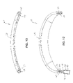
- FIG. 12 is a front view of a first crossbar construction with upper ends of the back frame illustrated in cross-section.
- FIG. 13 is a bottom view of the crossbar of FIG. 12 .
- FIG. 14 is a front view of a further embodiment of a crossbar having an alternate shape.
- FIG. 15 is an exploded view of the fabric cover construction of FIG. 9 being installed on the back frame with the crossbar of FIG. 14 .
- FIG. 16 is a perspective view of the crossbar installed on the side rails with the fabric cover in a raised position.
- FIG. 17 is a perspective view of the back frame assembly with the fabric cover lowered to an installed position.
- FIG. 18 is a perspective view of the back frame with the fabric cover of FIG. 6 illustrated in a raised position and aligned for installation on the side rails of the back frame.
- FIG. 19 is a perspective view of the fabric cover slid downwardly to a lowered position with a crossbar being slid into an upper hem pocket of the fabric cover.
- FIG. 20 is a perspective view of the back frame assembly with upper trim pieces shown prior to and after installation.
- FIG. 21 is a front view illustrating the upper corner connection of the crossbar and the back frame.
- FIG. 22 is an end cross-sectional view of the upper corner connection.
- FIG. 23 is a rear perspective view showing a fabric cover illustrated in phantom outline in a raised, partially installed position and a lowered, installed position.
- FIG. 24 illustrates the fabric cover with a retaining rod slid into nested engagement with a lower hem of the cover.
- FIG. 25 is a side cross-sectional view illustrating the retaining rod being swung forwardly into engagement with a locking bracket.
- FIG. 26 is a bottom view of the retaining rod fully engaged with the locking bracket.
- FIG. 27 is a side cross-sectional view illustrating a cover bracket positioned on the retaining rod.
- the invention relates to a chair 10 having an open-mesh back assembly 12 .
- the chair includes a base 14 comprising a plurality of legs 15 that extend radially outwardly and are supported on casters 16 .
- the base 14 further includes an upstanding post 17 .
- a seat assembly 19 is supported on the post 17 , which said seat assembly 19 includes a tilt control mechanism 20 which controls rearward tilting of the back assembly 12 relative to the seat assembly 19 .
- the tilt control mechanism 20 may be of any conventional construction and is illustrated as having a control housing 21 supported on the post 17 .
- a cushioned seat 22 is supported on the control housing 21 to provide an upward facing support surface 23 upon which a chair occupant is supported.
- the back assembly 12 comprises a generally L-shaped back frame 25 which includes a horizontally-extending mounting bracket 26 that is pivotally connected to the control housing 21 by a pivot pin 27 .
- the mounting bracket has a generally U-shaped, downward-opening configuration defined by a horizontal top plate 28 and downwardly depending sidewalls 29 .
- Each sidewall 29 includes a pivot hole 30 near the front thereof through which the pivot pin 27 is pivotally connected such that the entire back frame 25 is pivotally supported on the tilt control housing 21 and tiltable rearwardly about a horizontal pivot axis.
- the back frame 25 therefore may pivot rearwardly, i.e., clockwise about the pivot pin 27 as viewed in FIG. 1 .
- the pivotal connection between the mounting bracket 26 and the tilt control housing 21 is conventional and further detailed discussion as to this pivot connection is not required for an understanding of the present invention.
- the L-shape of the back frame 25 is defined by tubular uprights or siderails 32 which extend rearwardly from the mounting bracket 26 and then turn upwardly in a generally vertical direction to define the contour and shape of the back assembly 12 .
- each side post 32 is formed substantially identical to each other except for being formed in a mirror-image. Therefore, the following discussion references one of the posts 32 although it is equally applicable to the opposite post 32 .
- Each post 32 has a lower horizontal section 33 which extends forwardly into the hollow interior of the mounting bracket 26 and is rigidly affixed to the bracket 26 by welding or the like.
- the lower section 33 projects rearwardly and then turns outwardly to the side through a sidewardly curved section 34 which then curves upwardly through an upwardly curved section 35 .
- the upwardly curved sections 35 generally define the lower corners of the back assembly 12 as described in further detail herein.
- the curved sections 35 then extend upwardly and transition into vertical side sections 36 .
- the side sections 36 are provided with a contoured shape that generally defines the overall curvature and outline of the back assembly 12 .
- the side sections 36 not only may curve forwardly and rearwardly as seen in FIG. 1 but also inwardly or outwardly in the side-to-side direction as seen in FIG. 4 .
- the side sections 36 thereby are spaced sidewardly apart from each other to define an open interior region or back opening 38 which is the primary area in which the back of the chair occupant will be located and supported by the back assembly 12 as described in further detail herein.
- each side section 36 is formed with a tubular shape that defines an upper opening 41 .
- the inner sidewall of the upper end 40 also is formed with a rectangular lock notch 42 opening sidewardly through the entire thickness of the wall.
- a horizontal cross-brace 44 is provided with its opposite ends rigidly connected to the curved sections 34 .
- the cross-brace 44 has a central section which spans the open area 45 disposed between the lower rail sections 33 .
- retainer brackets 46 are mounted to each curved section 34 as seen in FIGS. 3 and 24 – 26 .
- Each retainer bracket 46 has a generally triangular shape when viewed from below as seen in FIG. 26 , and is defined by upper and lower walls 48 and 49 and an interior sidewall 50 .
- Each retainer bracket 46 also includes a connector notch 52 having a three-dimensional shape formed in the lower wall 49 and sidewall 50 . More particularly, each notch 52 includes a horizontal bottom portion 53 which is formed in the lower bracket wall 49 as seen in FIG. 26 . The notch 52 then further includes a vertical portion 54 which is formed in the sidewall 50 and extends continuously vertically from the inner end of the bottom portion 53 as seen in FIGS. 25 and 26 . The notch 52 also includes a horizontal top portion 55 which extends rearwardly from the upper end of the vertical portion 54 as seen in FIG. 25 to generally define an inverted L-shape in the sidewall 50 .
- the back assembly 12 also includes a retaining rod 56 ( FIGS. 23 and 24 ) which is adapted to span the open space 45 between the horizontal rail sections 33 and also have its opposite ends 57 seat within a respective notch 52 of a retainer bracket 46 .
- the retaining rod 56 is a separate component which is positionable in a horizontal orientation. The lateral spacing between the bottom notch portions 53 is sufficient to allow the opposite ends 57 of the retaining rod 56 to be slid vertically upwardly into the notches 52 as generally illustrated in FIGS. 25 and 26 .
- the retaining rod 56 is slid vertically along the vertical notch portions 54 and then slid rearwardly along the horizontal notch portions 55 such that the retaining rod 56 is supported vertically within the horizontal notch portions 55 as seen in FIG. 25 .
- the purpose of the retaining rod 56 is described in further detail hereinafter.
- the back assembly 12 additionally includes an interchangeable crossbar arrangement or spreader arrangement at the upper ends 40 of the siderails 32 .
- an interchangeable crossbar arrangement or spreader arrangement at the upper ends 40 of the siderails 32 .
- FIG. 2 three different crossbar embodiments are illustrated including a generally right-angle crossbar 60 wherein the corners 61 thereof have a right-angle shape.
- An additional curved crossbar 62 may alternatively be provided wherein the crossbar 62 is structurally and functionally the same as the crossbar 60 except for the overall aesthetic appearance thereof.
- a third rod-type crossbar 64 may be provided in combination with connector plugs 65 which permit the crossbar 64 to be supported on the siderails 32 and with a trim arrangement 66 which overlies the crossbar 64 and provides a finished aesthetic appearance.
- the crossbar 62 is formed with a main body 68 that is generally arch-shaped as seen in FIG. 12 and also curves forwardly as seen in FIG. 13 .
- the main body 68 is formed of a suitable molded material such as plastic.
- the main body 68 on the opposite lower ends thereof includes inserts 69 which are adapted to fit downwardly within the upper opening 41 on each rail end 40 .
- the insert 69 has an x-shaped cross-section as viewed from below in FIG. 13 which is adapted to be frictionally engaged within the tube end 40 in tight fitting engagement therewith.
- the insert 69 also includes a cantilevered locking finger 70 which projects vertically ( FIG.
- the finger 70 is able to deflect inwardly as the projection 71 slides along the interior surface 72 of the rail end 40 .
- the projection 71 is able to snap sidewardly into the lock notch 42 to prevent inadvertent removal of the crossbar 62 .
- the crossbar 62 is able to snap into the upper ends 40 of the siderails 32 such that the back frame 25 thereby has a generally rectangular configuration that is sized to support the entire back of a chair occupant. Additionally, the inserts 69 of the crossbar 62 are laterally spaced apart a sufficient distance so as to maintain the siderails 32 in a fully spread condition and prevent inward flexing of the siderails 32 .
- the crossbar 60 is structurally and functionally equivalent to the crossbar 62 .
- the crossbar 60 includes a horizontally elongate main body 73 having downwardly depending vertical sections 74 .
- the main body 73 includes inserts 75 at the lower ends of the vertical sections 74 which inserts 75 are formed identical to the inserts 69 and structurally cooperate and lock into the upper rail ends 40 as described above relative to FIGS. 12 and 13 .
- the primary difference between the crossbar 60 and the crossbar 62 is that the crossbar 60 has a more right-angle shape as opposed to the enhanced curvature provided in the crossbar 62 .
- the main body 73 of the crossbar 60 also is similar to the main body 68 in that it curves generally rearwardly to conform to the shape of a chair occupant's back.
- the inserts 75 further include cantilevered resilient fingers 76 having a lock projection 77 on the upper most end thereof.
- the crossbar 64 is provided as part of an overall crossbar assembly 80 comprising the aforementioned crossbar 64 , the connector plugs 65 and the trim arrangement 66 .
- the connector plug comprises a crossbar support section 81 which is formed with a blind bore 82 projecting downwardly therein.
- the support section 81 tapers upwardly as seen in FIG. 22 with the open upper end of the bore 82 adapted to receive one end of crossbar 64 therein.
- the plug 65 further includes a connector insert 83 which is formed substantially identical to the insert 69 described above.
- the insert 83 includes a cantilevered finger with a projection that is adapted to engage the lock notch 42 formed in the upper rail end 40 in the same manner as that generally illustrated in FIG. 12 .
- the insert 83 seats within the upper rail end 40 and has an annular rim 84 which is supported vertically on the upper edge 85 of the upper rail end 40 .
- the connector plug 65 therefore serves as an adapter to accommodate a different type of crossbar, namely the rod-type crossbar 64 .
- the crossbar 64 is formed of a steel rod that is bent at its opposite ends to define a connector flange 87 at each opposite end that is adapted to slide vertically downwardly into and be seated within the bore 82 .
- the crossbar 64 not only defines rectangular shape for the back frame 25 but also maintains the siderails 32 in the spread position.
- the crossbar assembly 80 further includes the trim arrangement 66 which comprises a horizontally-elongate front trim piece 89 and a rear trim piece 90 .
- the trim pieces 89 and 90 include cooperating connector parts which allow the trim pieces 89 and 90 to be snap locked together with the crossbar 64 sandwiched therebetween.
- the cooperating locking parts preferably include snap posts 92 which project forwardly from an inside face 93 of the rear trim piece 90 .
- the posts 92 are adapted to snap into respective openings on the opposing inside face of the front trim piece 89 . When snapped together the trim pieces 89 and 90 define an exposed upper edge section for the back assembly 12 as seen in FIG. 20 .
- three different back assemblies can be formed by providing one common back frame, in combination with the different, removable and interchangeable crossbars 60 , 62 and 64 .
- the different crossbars 60 , 62 and 64 define different aesthetic shapes and appearances for the back assembly 12 and are readily interchangeable and held in place without separate fasteners. As such, the construction of different chairs 10 can be readily varied during manufacture depending upon the crossbar construction being used.
- the back assembly 12 includes a fabric cover arrangement which overlies the back frame 25 and completes the finished aesthetic appearance of the back assembly 12 .
- the cover arrangements include either a dual-layer fabric cover 100 which is useable with the crossbar 60 or 62 , or a single-layer cover 101 which is useable with the crossbar 64 .
- the covers are formed of a resiliently stretchable or elastomeric material, and open interior pocket sections of the covers are adapted to receive the frame siderails 32 and the crossbars 60 , 62 or 64 therein.
- the covers 100 and 101 generally are formed of a resiliently stretchable open-mesh material wherein the lower edge of the covers 100 or 101 are stretched downwardly and then fixed to the back frame 25 to maintain the cover material taut and pull downwardly on any of the crossbars 60 , 62 or 64 to help retain the crossbars in fixed engagement with the siderails 32 .
- the cover 100 basically performs as an elastomeric fabric sock which fits over the back frame 25 and provides the finished aesthetic surfaces thereof.
- the cover 100 is formed of an elastomeric open-mesh material which is resiliently stretchable to tight fittingly conform to the shape of the back frame 25 and the contours provided by the siderails 32 . Further, the cover 100 is adapted to overlie the open area 38 defined between the siderails 32 and thereby resiliently support the occupant's back.
- the cover 100 is diagrammatically illustrated in FIGS. 9–11 as having first and second layers 103 and 104 which are joined together along the entirety of the side edges 105 and top edge 106 and a portion of the bottom edge 108 . More particularly, the fabric layers 103 and 104 are hemmed or seamed along the opposite side edges 105 and the top edge 106 to thereby define an open interior or pocket 107 between these opposing layers 103 and 104 .
- the seams or hems extend partially from the lower most corners along end portions 109 while a central portion 110 also is hemmed. This thereby defines two openings 111 which open into the hollow interior 107 and provide access thereto.
- the central hem portion 110 also serves as an engagement point which engages the retaining rod 56 to fixedly secure the bottom edge 108 to the retainer brackets 46 of the back frame 25 as will be discussed in greater detail herein.
- FIGS. 15–17 Assembly of the cover 100 to the back frame 25 is diagrammatically illustrated in FIGS. 15–17 .
- the cover 100 is adapted to completely enclose the siderails 32 any of the crossbars 60 or 62 within the open interior 107 . Since the cover 100 is completely closed along the side edges 105 and top edge 106 and partially enclosed across the bottom edge 108 , installment of the cover 100 is accomplished through the steps illustrated in FIGS. 15–17 .
- the crossbar 60 has one end inserted into one of the openings 111 and then threaded out of the other opening 111 such that the opposite ends of the crossbar 60 , such as the end portions 74 , project downwardly from the openings 111 .
- the inserts 75 on the crossbar 60 are then plugged into the openings 41 formed in the siderails 32 which then traps the cover 100 on the back frame 25 .
- the cover 100 is slid downwardly so as to completely enclose the back frame 25 as seen in FIG. 17 .
- the lower edge 108 thereof is fixedly attached to the retainer brackets 46 as diagrammatically illustrated in FIGS. 23–25 .
- the cover 100 is slid downwardly as indicated by reference arrow 112 to the fully installed position designated by reference arrow 113 .
- the central hem section 110 hangs downwardly while the retaining rod 56 is then inserted into one opening 111 until the opposite ends 57 project outwardly from the opposite sides of the central hem section 110 as seen in FIG. 24 .
- the retaining rod 56 when engaged with the central hem section 110 is pulled downwardly as indicated by reference arrow 114 such that the overall fabric material of the cover 100 is stretched taut. Thereafter, the retaining rod 56 is swung forwardly as indicated by reference arrow 115 and then seated within the connector notches 52 as indicated by reference arrow 116 .
- the cover material 100 therefore extends rearwardly and then wraps forwardly about the cross brace 44 so that the back is fully enclosed by the cover material 100 as seen in the various Figures including FIG. 26 .
- the only retaining device holding the cover 100 in position as well as holding the crossbar 60 or 62 in place on the siderails 32 is the retaining rod 56 and the resilient stretching of the fabric material.
- a cover channel 120 is provided having upper and lower walls 121 and 122 , a forward wall 123 and opposite sidewalls 124 .
- the sidewalls 124 include an engagement channel 125 having an entry section 126 and a vertical interior section 127 .
- the cover channel 120 thereby fits rearwardly over the retaining rod 56 and is locked in place thereon to enclose the arrangement of the retaining rod 56 .
- the cover 100 thereby may fit onto either of the crossbars 60 and 62 . Due to the resiliency of this cover 100 , the upper cover edge 106 is adapted to stretch and conform to the different geometric configurations of the crossbars 60 and 62 .
- this cover is illustrated in FIGS. 6–8 .
- the same fabric material is used except that it is hemmed so as to define a tubular pocket extending about the entire periphery of the cover 101 .
- the tubular pocket is defined by a rectangular hemline 130 which forms vertical side pockets 131 , a horizontal top pocket 132 and a horizontal bottom pocket 133 .
- the side pockets 131 are completely enclosed along the vertical side edges 134 while the bottom pocket 133 has opposite end hem portions 135 and a central hem portion 136 which are formed substantially the same as the hem portions 108 and 109 on the cover 100 .
- the lower portion of the cover 101 thereby functions and is connected to the back frame 25 similar to the cover 100 as will be described in further detail herein.
- a pair of laterally spaced apart pocket openings 137 are formed on the opposite ends of the central hem section 136 .
- the upper pocket 132 functions similar to the cover 100 in that it receives the crossbar horizontally therein and holds the crossbar 64 on the siderails 32 .
- the upper edge 140 of the cover 101 is formed with a pair of relatively small crossbar openings 141 in the seam near the upper corners thereof. Therefore, the cover 101 functions similar to the cover 100 in that a crossbar 64 is received within an open interior portion or pocket of the cover 100 through appropriate corner openings.
- the corner openings are defined by openings 141 at the top corners while separate bottom openings 137 are provided to accommodate the retaining rod 56 as described further herein.
- the cover 101 When installed, the cover 101 defines a body support area 142 which completely overlies the open region 38 between the uprights 32 to support the occupant's back.
- the siderails 32 include the plugs 65 thereon wherein the upper ends of the siderails 32 are inserted into the side pockets 131 through the lower corner openings 137 .
- one end of the crossbar 64 is inserted into the upper right corner opening 141 as indicated by reference arrow 144 and then slid horizontally through the top pocket 132 until the crossbar 64 is enclosed entirely within this top pocket 132 .
- the opposite crossbar ends 87 thereby align with and then are inserted downwardly into engagement with the plugs 65 as generally illustrated in FIGS. 21 and 22 .
- the lower end of the cover 101 is pulled downwardly over the entire back frame 25 similar to the cover 100 described above.
- the trim pieces 89 and 90 are snapped over the exterior of the cover 101 to enclose the corner openings 141 as well as the crossbar 64 and end plugs 65 which may be visible therethrough.
- the central hem portion 136 and the openings 137 are adapted to receive the retaining rod 56 therethrough in the same manner as the cover 100 and therefore, the structure and assembly steps illustrated in FIGS. 23–27 are also applicable to the cover 101 and are not described in greater detail herein.
- fasteners 150 may be snapped through the cover material 101 into engagement with the fastener openings 151 illustrated in FIG. 26 which thereby holds the cover 101 in place and ensures that the cover 101 completely encloses the lower structure of the back frame 25 .
- the cover channel 120 ( FIG. 27 ) then is positioned in place on the retaining rod 56 to further finish the aesthetic appearance of the back frame 25 .
- the back assembly 12 provides an improved construction which may be readily assembled and manufactured using a common back frame 25 , different style crossbars 60 , 62 or 64 and an appropriate cover 100 or 101 . Assembly of the back assembly 12 is accomplished without the use of separate fasteners or the like and only requires a retaining rod 56 which is held in place due to the resilient stretching force generated by the covers 100 or 101 . This provides for easy assembly and a cover 100 or 101 which readily conforms to the shape of the back frame 25 .
Abstract
Description
Claims (26)
Priority Applications (2)
| Application Number | Priority Date | Filing Date | Title |
|---|---|---|---|
| US10/434,667 US7055911B2 (en) | 2003-05-08 | 2003-05-08 | Mesh chair |
| CA2430574A CA2430574C (en) | 2003-05-08 | 2003-05-30 | Mesh chair |
Applications Claiming Priority (1)
| Application Number | Priority Date | Filing Date | Title |
|---|---|---|---|
| US10/434,667 US7055911B2 (en) | 2003-05-08 | 2003-05-08 | Mesh chair |
Publications (2)
| Publication Number | Publication Date |
|---|---|
| US20040222683A1 US20040222683A1 (en) | 2004-11-11 |
| US7055911B2 true US7055911B2 (en) | 2006-06-06 |
Family
ID=33416752
Family Applications (1)
| Application Number | Title | Priority Date | Filing Date |
|---|---|---|---|
| US10/434,667 Expired - Lifetime US7055911B2 (en) | 2003-05-08 | 2003-05-08 | Mesh chair |
Country Status (2)
| Country | Link |
|---|---|
| US (1) | US7055911B2 (en) |
| CA (1) | CA2430574C (en) |
Cited By (48)
| Publication number | Priority date | Publication date | Assignee | Title |
|---|---|---|---|---|
| US20070126267A1 (en) * | 2005-12-01 | 2007-06-07 | Hoffman D S | Reclining seating unit with backrest support frame and cloth backrest support deck |
| US20080290712A1 (en) * | 2006-10-04 | 2008-11-27 | Formway Furniture Limited | Chair |
| KR100883189B1 (en) | 2006-07-24 | 2009-02-12 | 가부시끼가이샤 오까무라세이사꾸쇼 | A backrest device in a chair |
| USD613084S1 (en) | 2008-12-12 | 2010-04-06 | Formway Furniture Limited | Chair |
| USD615784S1 (en) | 2008-04-09 | 2010-05-18 | Formway Furniture Limited | Chair back |
| USD616213S1 (en) | 2008-04-09 | 2010-05-25 | Formway Furniture Limited | Chair |
| US20100176646A1 (en) * | 2009-01-15 | 2010-07-15 | Rowland David L | Panel |
| US20110175423A1 (en) * | 2007-09-20 | 2011-07-21 | Herman Miller, Inc. | Load support structure |
| US20120007400A1 (en) * | 2010-04-13 | 2012-01-12 | Yves Behar | Seating structure with a contoured flexible backrest |
| US20120025574A1 (en) * | 2008-12-12 | 2012-02-02 | Formway Furniture Limited | Chair, a support, and components |
| US20120212027A1 (en) * | 2009-10-19 | 2012-08-23 | Okamura Corporation | Backrest for chair |
| US20120223566A1 (en) * | 2009-10-19 | 2012-09-06 | Ken Nakayama | Backrest for chair |
| US20120313419A1 (en) * | 2010-02-10 | 2012-12-13 | Okamura Corporation | Stretching structure of chair upholstery material |
| USD688497S1 (en) | 2012-09-20 | 2013-08-27 | Steelcase Inc. | Chair |
| USD689314S1 (en) | 2012-09-20 | 2013-09-10 | Steelcase Inc. | Chair |
| USD689317S1 (en) | 2012-09-20 | 2013-09-10 | Steelcase Inc. | Chair |
| USD694538S1 (en) | 2012-09-20 | 2013-12-03 | Steelcase Inc. | Chair |
| USD699959S1 (en) | 2012-09-20 | 2014-02-25 | Steelcase Inc. | Chair |
| US8973990B2 (en) | 2012-09-20 | 2015-03-10 | Steelcase Inc. | Chair assembly |
| US8998338B2 (en) | 2012-09-20 | 2015-04-07 | Steelcase Inc. | Chair assembly with upholstery covering |
| US8998339B2 (en) | 2012-09-20 | 2015-04-07 | Steelcase Inc. | Chair assembly with upholstery covering |
| US20150283927A1 (en) * | 2014-04-03 | 2015-10-08 | Howard Velasco | Lightweight headrest assembly |
| USD742678S1 (en) | 2012-09-20 | 2015-11-10 | Steelcase Inc. | Chair assembly |
| USD743712S1 (en) | 2013-03-15 | 2015-11-24 | Herman Miller, Inc. | Chair |
| USD758774S1 (en) | 2015-04-24 | 2016-06-14 | Steelcase Inc. | Headrest assembly |
| USD759415S1 (en) | 2015-04-24 | 2016-06-21 | Steelcase Inc. | Headrest |
| USD760526S1 (en) | 2015-04-24 | 2016-07-05 | Steelcase Inc. | Headrest assembly |
| US20160242550A1 (en) * | 2015-02-21 | 2016-08-25 | Ben Alton Hammock | Chair Assembly |
| USD781604S1 (en) | 2015-04-24 | 2017-03-21 | Steelcase Inc. | Chair |
| USD781605S1 (en) | 2015-04-24 | 2017-03-21 | Steelcase Inc. | Chair |
| US9913540B2 (en) | 2012-09-21 | 2018-03-13 | Steelcase Inc. | Chair construction |
| US10874220B2 (en) | 2015-01-16 | 2020-12-29 | Herman Miller, Inc. | Zoned suspension seating structure |
| US11109683B2 (en) | 2019-02-21 | 2021-09-07 | Steelcase Inc. | Body support assembly and method for the use and assembly thereof |
| USD935824S1 (en) | 2020-02-19 | 2021-11-16 | Steelcase Inc. | Seat |
| USD937024S1 (en) | 2020-02-19 | 2021-11-30 | Steelcase Inc. | Backrest |
| USD936985S1 (en) | 2020-02-19 | 2021-11-30 | Steelcase Inc. | Chair |
| USD936984S1 (en) | 2020-02-19 | 2021-11-30 | Steelcase Inc. | Chair |
| USD937595S1 (en) | 2020-02-19 | 2021-12-07 | Steelcase Inc. | Chair |
| US11229294B2 (en) | 2012-09-20 | 2022-01-25 | Steelcase Inc. | Chair assembly with upholstery covering |
| US11304528B2 (en) | 2012-09-20 | 2022-04-19 | Steelcase Inc. | Chair assembly with upholstery covering |
| USD951690S1 (en) | 2020-02-19 | 2022-05-17 | Steelcase Inc. | Chair |
| US11357329B2 (en) | 2019-12-13 | 2022-06-14 | Steelcase Inc. | Body support assembly and methods for the use and assembly thereof |
| USD961315S1 (en) | 2020-02-19 | 2022-08-23 | Steelcase Inc. | Chair |
| USD961317S1 (en) | 2020-02-19 | 2022-08-23 | Steelcase Inc. | Backrest |
| USD988048S1 (en) | 2021-01-20 | 2023-06-06 | Steelcase Inc. | Lumbar support |
| USD988049S1 (en) | 2021-05-12 | 2023-06-06 | Steelcase Inc. | Lumbar support |
| USD995179S1 (en) | 2021-01-20 | 2023-08-15 | Steelcase Inc. | Chair with lumbar support |
| USD995180S1 (en) | 2021-05-12 | 2023-08-15 | Steelcase Inc. | Chair with lumbar support |
Families Citing this family (5)
| Publication number | Priority date | Publication date | Assignee | Title |
|---|---|---|---|---|
| ES2344824B1 (en) * | 2009-03-06 | 2011-06-20 | Figueras International Seating, S.L. | "ARMCHAIR FOR AUDITORIAL OR SIMILAR ROOMS". |
| JP6529154B2 (en) * | 2014-10-24 | 2019-06-12 | 株式会社オカムラ | Chair load support member and chair |
| US10150538B1 (en) | 2015-04-16 | 2018-12-11 | David Salz | Resilient structural boat seating and rowing apparatus |
| USD793758S1 (en) * | 2015-12-28 | 2017-08-08 | Kraco Enterprises, Llc | Seat cushion |
| US10631651B1 (en) * | 2019-08-06 | 2020-04-28 | Sunflow, Inc. | Chair |
Citations (23)
| Publication number | Priority date | Publication date | Assignee | Title |
|---|---|---|---|---|
| US2204722A (en) | 1940-06-18 | -x xx xx | ||
| US2251318A (en) | 1937-12-17 | 1941-08-05 | Mishawaka Rubber & Woolen Mfg | Cushioning facility for seats and the like |
| US2716443A (en) | 1954-05-25 | 1955-08-30 | Myron P Laughlin | Seat back support |
| US3230011A (en) * | 1963-07-05 | 1966-01-18 | Miller Herman Inc | Seating |
| US4230364A (en) * | 1978-04-12 | 1980-10-28 | Parker Charles F | Multipurpose chair |
| US4284305A (en) | 1979-02-01 | 1981-08-18 | Nautical Interiors Corporation | Apparatus for upholstering a vehicle chair |
| USD267757S (en) | 1981-01-26 | 1983-02-01 | Leib Roger K | Chair |
| US4431229A (en) | 1981-12-15 | 1984-02-14 | Knoll International, Inc. | Webbing tensioning assembly |
| US5207478A (en) | 1991-02-28 | 1993-05-04 | Gerry Baby Products Company | Collapsible infant seat |
| US5360258A (en) | 1992-01-07 | 1994-11-01 | Maurice Adam | Portable single and multiple unit baby support seat |
| US5393126A (en) * | 1993-06-21 | 1995-02-28 | Art Design International Inc. | Tubular frame seating structure with tension sleeve |
| US5582463A (en) | 1995-07-10 | 1996-12-10 | Hoover Universal, Inc. | Seat assembly with improved attachment of a suspension mat to a seat frame |
| US6050646A (en) | 1997-12-10 | 2000-04-18 | Sedus Stoll Ag | Backrest |
| USD423260S (en) | 1999-05-17 | 2000-04-25 | Grove James E | Mesh back chair with cushions |
| USD423259S (en) | 1999-05-10 | 2000-04-25 | Grove James E | Mesh back chair |
| US6113186A (en) | 1999-05-21 | 2000-09-05 | Chromcraft/Revington Company | Multiple seat assembly I |
| US6220661B1 (en) | 1999-04-19 | 2001-04-24 | Steelcase Development Inc. | Chair back and method of assembly |
| US6231125B1 (en) | 1997-12-26 | 2001-05-15 | Ts Tech Co., Ltd. | Seat with resilient sheet-formed seat cushion |
| US6254190B1 (en) * | 1999-09-29 | 2001-07-03 | Peter G. G. Gregory | Chair having a seat with differential front and rear support portions |
| US20020003371A1 (en) | 2000-07-06 | 2002-01-10 | Werner Link | Back of a chair |
| US6341822B2 (en) * | 1999-08-13 | 2002-01-29 | Homecrest Industries Incorporated | Chair construction and method of making same |
| US6375269B1 (en) | 1997-11-25 | 2002-04-23 | Ts Tech Co., Ltd. | Seat having seating face made of sheet resilient material |
| US6698839B2 (en) * | 2001-10-02 | 2004-03-02 | Dauphin Entwicklungs-U. Beteiligungs-Gmbh | Back of chair |
-
2003
- 2003-05-08 US US10/434,667 patent/US7055911B2/en not_active Expired - Lifetime
- 2003-05-30 CA CA2430574A patent/CA2430574C/en not_active Expired - Lifetime
Patent Citations (26)
| Publication number | Priority date | Publication date | Assignee | Title |
|---|---|---|---|---|
| US2204722A (en) | 1940-06-18 | -x xx xx | ||
| US2251318A (en) | 1937-12-17 | 1941-08-05 | Mishawaka Rubber & Woolen Mfg | Cushioning facility for seats and the like |
| US2716443A (en) | 1954-05-25 | 1955-08-30 | Myron P Laughlin | Seat back support |
| US3230011A (en) * | 1963-07-05 | 1966-01-18 | Miller Herman Inc | Seating |
| US4230364A (en) * | 1978-04-12 | 1980-10-28 | Parker Charles F | Multipurpose chair |
| US4284305A (en) | 1979-02-01 | 1981-08-18 | Nautical Interiors Corporation | Apparatus for upholstering a vehicle chair |
| USD267757S (en) | 1981-01-26 | 1983-02-01 | Leib Roger K | Chair |
| US4431229A (en) | 1981-12-15 | 1984-02-14 | Knoll International, Inc. | Webbing tensioning assembly |
| US5207478A (en) | 1991-02-28 | 1993-05-04 | Gerry Baby Products Company | Collapsible infant seat |
| US5360258A (en) | 1992-01-07 | 1994-11-01 | Maurice Adam | Portable single and multiple unit baby support seat |
| US5393126A (en) * | 1993-06-21 | 1995-02-28 | Art Design International Inc. | Tubular frame seating structure with tension sleeve |
| US5582463A (en) | 1995-07-10 | 1996-12-10 | Hoover Universal, Inc. | Seat assembly with improved attachment of a suspension mat to a seat frame |
| US6375269B1 (en) | 1997-11-25 | 2002-04-23 | Ts Tech Co., Ltd. | Seat having seating face made of sheet resilient material |
| US6050646A (en) | 1997-12-10 | 2000-04-18 | Sedus Stoll Ag | Backrest |
| US6231125B1 (en) | 1997-12-26 | 2001-05-15 | Ts Tech Co., Ltd. | Seat with resilient sheet-formed seat cushion |
| US6220661B1 (en) | 1999-04-19 | 2001-04-24 | Steelcase Development Inc. | Chair back and method of assembly |
| USD423259S (en) | 1999-05-10 | 2000-04-25 | Grove James E | Mesh back chair |
| USD423260S (en) | 1999-05-17 | 2000-04-25 | Grove James E | Mesh back chair with cushions |
| US6113186A (en) | 1999-05-21 | 2000-09-05 | Chromcraft/Revington Company | Multiple seat assembly I |
| US6341822B2 (en) * | 1999-08-13 | 2002-01-29 | Homecrest Industries Incorporated | Chair construction and method of making same |
| US6345428B2 (en) | 1999-08-13 | 2002-02-12 | Homecrest Industries Incorporated | Chair construction and method of making same |
| US6254190B1 (en) * | 1999-09-29 | 2001-07-03 | Peter G. G. Gregory | Chair having a seat with differential front and rear support portions |
| US20010030457A1 (en) | 1999-09-29 | 2001-10-18 | Gregory Peter G. G. | Chair |
| US6623079B2 (en) * | 1999-09-29 | 2003-09-23 | Peter G. G. Gregory | Chair |
| US20020003371A1 (en) | 2000-07-06 | 2002-01-10 | Werner Link | Back of a chair |
| US6698839B2 (en) * | 2001-10-02 | 2004-03-02 | Dauphin Entwicklungs-U. Beteiligungs-Gmbh | Back of chair |
Cited By (108)
| Publication number | Priority date | Publication date | Assignee | Title |
|---|---|---|---|---|
| US20070126267A1 (en) * | 2005-12-01 | 2007-06-07 | Hoffman D S | Reclining seating unit with backrest support frame and cloth backrest support deck |
| KR100883189B1 (en) | 2006-07-24 | 2009-02-12 | 가부시끼가이샤 오까무라세이사꾸쇼 | A backrest device in a chair |
| US8029060B2 (en) | 2006-10-04 | 2011-10-04 | Formway Furniture Limited | Chair |
| US20080290712A1 (en) * | 2006-10-04 | 2008-11-27 | Formway Furniture Limited | Chair |
| US8613481B2 (en) | 2006-10-04 | 2013-12-24 | Formway Furniture Limited | Chair |
| US8096615B2 (en) | 2006-10-04 | 2012-01-17 | Formay Furniture Limited | Chair |
| US8668265B2 (en) | 2006-10-04 | 2014-03-11 | Formway Furniture Limited | Chair |
| US8888183B2 (en) | 2006-10-04 | 2014-11-18 | Formway Furniture Limited | Chair |
| US8087727B2 (en) | 2006-10-04 | 2012-01-03 | Formway Furniture Limited | Chair |
| US10856662B2 (en) | 2007-09-20 | 2020-12-08 | Herman Miller, Inc. | Load support structure |
| US20130099548A1 (en) * | 2007-09-20 | 2013-04-25 | Herman Miller, Inc. | Load support structure |
| US8967726B2 (en) * | 2007-09-20 | 2015-03-03 | Herman Miller, Inc. | Load support structure |
| US11330905B2 (en) | 2007-09-20 | 2022-05-17 | MillerKnoll, Inc. | Load support structure |
| US20110175423A1 (en) * | 2007-09-20 | 2011-07-21 | Herman Miller, Inc. | Load support structure |
| US9668580B2 (en) | 2007-09-20 | 2017-06-06 | Herman Miller, Inc. | Load support structure |
| US10016060B2 (en) * | 2007-09-20 | 2018-07-10 | Herman Miller, Inc. | Load support structure |
| US10820706B2 (en) | 2007-09-20 | 2020-11-03 | Herman Miller, Inc. | Load support structure |
| US8282169B2 (en) * | 2007-09-20 | 2012-10-09 | Herman Miller, Inc. | Load support structure |
| US20150238016A1 (en) * | 2007-09-20 | 2015-08-27 | Herman Miller, Inc. | Load support structure |
| USD615784S1 (en) | 2008-04-09 | 2010-05-18 | Formway Furniture Limited | Chair back |
| USD616213S1 (en) | 2008-04-09 | 2010-05-25 | Formway Furniture Limited | Chair |
| US9033421B2 (en) * | 2008-12-12 | 2015-05-19 | Formway Furniture Limited | Chair, a support, and components |
| USD613084S1 (en) | 2008-12-12 | 2010-04-06 | Formway Furniture Limited | Chair |
| US20120025574A1 (en) * | 2008-12-12 | 2012-02-02 | Formway Furniture Limited | Chair, a support, and components |
| US9622579B2 (en) | 2008-12-12 | 2017-04-18 | Formway Furniture Limited | Chair, a support, and components |
| US7871131B2 (en) * | 2009-01-15 | 2011-01-18 | Rowland David L | Panel |
| WO2010083142A1 (en) * | 2009-01-15 | 2010-07-22 | Rowland David L | Improved panel |
| US20100176646A1 (en) * | 2009-01-15 | 2010-07-15 | Rowland David L | Panel |
| US20120223566A1 (en) * | 2009-10-19 | 2012-09-06 | Ken Nakayama | Backrest for chair |
| US20120212027A1 (en) * | 2009-10-19 | 2012-08-23 | Okamura Corporation | Backrest for chair |
| US8794701B2 (en) * | 2009-10-19 | 2014-08-05 | Okamura Corporation | Backrest for chair |
| US20120313419A1 (en) * | 2010-02-10 | 2012-12-13 | Okamura Corporation | Stretching structure of chair upholstery material |
| US8777321B2 (en) * | 2010-02-10 | 2014-07-15 | Okamura Corporation | Stretching structure of chair upholstery material |
| US8449037B2 (en) * | 2010-04-13 | 2013-05-28 | Herman Miller, Inc. | Seating structure with a contoured flexible backrest |
| US9301615B2 (en) | 2010-04-13 | 2016-04-05 | Herman Miller, Inc. | Seating structure with a contoured flexible backrest |
| US20120007400A1 (en) * | 2010-04-13 | 2012-01-12 | Yves Behar | Seating structure with a contoured flexible backrest |
| US9706853B2 (en) | 2012-09-20 | 2017-07-18 | Steelcase Inc. | Chair assembly |
| USD698166S1 (en) | 2012-09-20 | 2014-01-28 | Steelcase Inc. | Chair |
| US8998339B2 (en) | 2012-09-20 | 2015-04-07 | Steelcase Inc. | Chair assembly with upholstery covering |
| US9526339B2 (en) | 2012-09-20 | 2016-12-27 | Steelcase Inc. | Control assembly for chair |
| US9049935B2 (en) | 2012-09-20 | 2015-06-09 | Steelcase Inc. | Control assembly for chair |
| USD694538S1 (en) | 2012-09-20 | 2013-12-03 | Steelcase Inc. | Chair |
| US10842281B2 (en) | 2012-09-20 | 2020-11-24 | Steelcase Inc. | Control assembly for chair |
| US9167910B2 (en) | 2012-09-20 | 2015-10-27 | Steelcase Inc. | Chair assembly |
| US9173491B2 (en) | 2012-09-20 | 2015-11-03 | Steelcase Inc. | Chair assembly with upholstery covering |
| USD742678S1 (en) | 2012-09-20 | 2015-11-10 | Steelcase Inc. | Chair assembly |
| US9179777B2 (en) | 2012-09-20 | 2015-11-10 | Steelcase Inc. | Method of assembling a chair component |
| US11229294B2 (en) | 2012-09-20 | 2022-01-25 | Steelcase Inc. | Chair assembly with upholstery covering |
| USD750406S1 (en) | 2012-09-20 | 2016-03-01 | Steelcase Inc. | Chair assembly |
| US10765212B2 (en) | 2012-09-20 | 2020-09-08 | Steelcase Inc. | Chair assembly with upholstery covering |
| US8973990B2 (en) | 2012-09-20 | 2015-03-10 | Steelcase Inc. | Chair assembly |
| US9345328B2 (en) | 2012-09-20 | 2016-05-24 | Steelcase Inc. | Chair assembly with upholstery covering |
| US10413083B2 (en) | 2012-09-20 | 2019-09-17 | Steelcase Inc. | Chair assembly |
| US10264889B2 (en) | 2012-09-20 | 2019-04-23 | Steelcase Inc. | Chair assembly with upholstery covering |
| US11464341B2 (en) | 2012-09-20 | 2022-10-11 | Steelcase Inc. | Chair assembly with upholstery covering |
| US10165861B2 (en) | 2012-09-20 | 2019-01-01 | Steelcase Inc. | Chair assembly with upholstery covering |
| USD688497S1 (en) | 2012-09-20 | 2013-08-27 | Steelcase Inc. | Chair |
| US9408467B2 (en) | 2012-09-20 | 2016-08-09 | Steelcase Inc. | Chair assembly with upholstery covering |
| USD694539S1 (en) | 2012-09-20 | 2013-12-03 | Steelcase Inc. | Chair |
| US8998338B2 (en) | 2012-09-20 | 2015-04-07 | Steelcase Inc. | Chair assembly with upholstery covering |
| USD689318S1 (en) | 2012-09-20 | 2013-09-10 | Steelcase Inc. | Chair |
| US9986848B2 (en) | 2012-09-20 | 2018-06-05 | Steelcase Inc. | Chair assembly method |
| USD689312S1 (en) | 2012-09-20 | 2013-09-10 | Steelcase Inc. | Chair |
| US11304528B2 (en) | 2012-09-20 | 2022-04-19 | Steelcase Inc. | Chair assembly with upholstery covering |
| USD689317S1 (en) | 2012-09-20 | 2013-09-10 | Steelcase Inc. | Chair |
| USD689314S1 (en) | 2012-09-20 | 2013-09-10 | Steelcase Inc. | Chair |
| US9681750B2 (en) | 2012-09-20 | 2017-06-20 | Steelcase Inc. | Chair assembly with upholstery covering |
| USD699959S1 (en) | 2012-09-20 | 2014-02-25 | Steelcase Inc. | Chair |
| US9826839B2 (en) | 2012-09-20 | 2017-11-28 | Steelcase Inc. | Chair assembly with upholstery covering |
| US9913540B2 (en) | 2012-09-21 | 2018-03-13 | Steelcase Inc. | Chair construction |
| US10674826B2 (en) | 2012-09-21 | 2020-06-09 | Steelcase Inc. | Chair construction |
| USD761029S1 (en) | 2013-03-15 | 2016-07-12 | Herman Miller, Inc. | Chair with desk |
| USD761048S1 (en) | 2013-03-15 | 2016-07-12 | Herman Miller, Inc. | Chair |
| USD777474S1 (en) | 2013-03-15 | 2017-01-31 | Herman Miller, Inc. | Desk |
| USD752893S1 (en) | 2013-03-15 | 2016-04-05 | Herman Miller, Inc. | Chair |
| USD743712S1 (en) | 2013-03-15 | 2015-11-24 | Herman Miller, Inc. | Chair |
| US9579999B2 (en) * | 2014-04-03 | 2017-02-28 | Franklin Products, Inc. | Lightweight headrest assembly |
| US20150283927A1 (en) * | 2014-04-03 | 2015-10-08 | Howard Velasco | Lightweight headrest assembly |
| US11825957B2 (en) | 2015-01-16 | 2023-11-28 | MillerKnoll, Inc. | Zoned suspension seating structure |
| US10874220B2 (en) | 2015-01-16 | 2020-12-29 | Herman Miller, Inc. | Zoned suspension seating structure |
| US20160242550A1 (en) * | 2015-02-21 | 2016-08-25 | Ben Alton Hammock | Chair Assembly |
| USD759415S1 (en) | 2015-04-24 | 2016-06-21 | Steelcase Inc. | Headrest |
| USD758774S1 (en) | 2015-04-24 | 2016-06-14 | Steelcase Inc. | Headrest assembly |
| USD781605S1 (en) | 2015-04-24 | 2017-03-21 | Steelcase Inc. | Chair |
| USD781604S1 (en) | 2015-04-24 | 2017-03-21 | Steelcase Inc. | Chair |
| USD760526S1 (en) | 2015-04-24 | 2016-07-05 | Steelcase Inc. | Headrest assembly |
| US11910934B2 (en) | 2019-02-21 | 2024-02-27 | Steelcase Inc. | Body support assembly and methods for the use and assembly thereof |
| US11109683B2 (en) | 2019-02-21 | 2021-09-07 | Steelcase Inc. | Body support assembly and method for the use and assembly thereof |
| US11602223B2 (en) | 2019-02-21 | 2023-03-14 | Steelcase Inc. | Body support assembly and methods for the use and assembly thereof |
| US11357329B2 (en) | 2019-12-13 | 2022-06-14 | Steelcase Inc. | Body support assembly and methods for the use and assembly thereof |
| US11805913B2 (en) | 2019-12-13 | 2023-11-07 | Steelcase Inc. | Body support assembly and methods for the use and assembly thereof |
| US11786039B2 (en) | 2019-12-13 | 2023-10-17 | Steelcase Inc. | Body support assembly and methods for the use and assembly thereof |
| USD961281S1 (en) | 2020-02-19 | 2022-08-23 | Steelcase Inc. | Chair |
| USD951690S1 (en) | 2020-02-19 | 2022-05-17 | Steelcase Inc. | Chair |
| USD935824S1 (en) | 2020-02-19 | 2021-11-16 | Steelcase Inc. | Seat |
| USD961315S1 (en) | 2020-02-19 | 2022-08-23 | Steelcase Inc. | Chair |
| USD961280S1 (en) | 2020-02-19 | 2022-08-23 | Steelcase Inc. | Chair |
| USD961317S1 (en) | 2020-02-19 | 2022-08-23 | Steelcase Inc. | Backrest |
| USD951691S1 (en) | 2020-02-19 | 2022-05-17 | Steelcase Inc. | Chair |
| USD961316S1 (en) | 2020-02-19 | 2022-08-23 | Steelcase Inc. | Chair |
| USD937024S1 (en) | 2020-02-19 | 2021-11-30 | Steelcase Inc. | Backrest |
| USD936985S1 (en) | 2020-02-19 | 2021-11-30 | Steelcase Inc. | Chair |
| USD936984S1 (en) | 2020-02-19 | 2021-11-30 | Steelcase Inc. | Chair |
| USD937595S1 (en) | 2020-02-19 | 2021-12-07 | Steelcase Inc. | Chair |
| USD995179S1 (en) | 2021-01-20 | 2023-08-15 | Steelcase Inc. | Chair with lumbar support |
| USD988048S1 (en) | 2021-01-20 | 2023-06-06 | Steelcase Inc. | Lumbar support |
| USD995180S1 (en) | 2021-05-12 | 2023-08-15 | Steelcase Inc. | Chair with lumbar support |
| USD988049S1 (en) | 2021-05-12 | 2023-06-06 | Steelcase Inc. | Lumbar support |
Also Published As
| Publication number | Publication date |
|---|---|
| US20040222683A1 (en) | 2004-11-11 |
| CA2430574C (en) | 2011-06-21 |
| CA2430574A1 (en) | 2004-11-08 |
Similar Documents
| Publication | Publication Date | Title |
|---|---|---|
| US7055911B2 (en) | Mesh chair | |
| US7025424B2 (en) | Chair back for a chair | |
| CA2881698C (en) | Chair assembly | |
| US5662383A (en) | Apparatus for attaching fabric to a chair frame | |
| US8251454B2 (en) | Backrest of the chair and adaptation device for the same | |
| US6508509B2 (en) | Back for seating unit and method of assembly | |
| US8403421B2 (en) | Single frame sling chair | |
| WO2006041078A1 (en) | Stretching structure of stretching material in chair and backrest of chair | |
| US5288136A (en) | Chair membrane fastener | |
| US5248186A (en) | Bumper edge guard for upholstered seating furniture having a core member | |
| US5244249A (en) | Lawn chair | |
| CN110027447A (en) | Vehicle seat | |
| JP4642346B2 (en) | Chair upholstery structure | |
| US7731291B2 (en) | Single frame sling chair | |
| US20030160495A1 (en) | Retention method for flexible seating material | |
| US20020043186A1 (en) | Securement arrangement | |
| JP7057998B2 (en) | Chair | |
| US5652982A (en) | Wall hammock for use in the sitting position | |
| JP7448354B2 (en) | Chair | |
| CA2470488C (en) | Chair back for a chair | |
| KR200164640Y1 (en) | The back of a chair | |
| JPS5927794Y2 (en) | cushion cover | |
| JPS6038919Y2 (en) | chair back member | |
| JPH08337138A (en) | Collapsible child seat | |
| JP2020049116A (en) | Chair |
Legal Events
| Date | Code | Title | Description |
|---|---|---|---|
| AS | Assignment |
Owner name: HAWORTH, INC., MICHIGAN Free format text: ASSIGNMENT OF ASSIGNORS INTEREST;ASSIGNORS:SIMPSON, STEPHEN J.;GESSLER, BRIAN;RUTMAN, MATT;REEL/FRAME:014436/0687 Effective date: 20030813 |
|
| STCF | Information on status: patent grant |
Free format text: PATENTED CASE |
|
| CC | Certificate of correction | ||
| FEPP | Fee payment procedure |
Free format text: PAT HOLDER NO LONGER CLAIMS SMALL ENTITY STATUS, ENTITY STATUS SET TO UNDISCOUNTED (ORIGINAL EVENT CODE: STOL); ENTITY STATUS OF PATENT OWNER: LARGE ENTITY |
|
| REFU | Refund |
Free format text: REFUND - SURCHARGE, PETITION TO ACCEPT PYMT AFTER EXP, UNINTENTIONAL (ORIGINAL EVENT CODE: R2551); ENTITY STATUS OF PATENT OWNER: LARGE ENTITY |
|
| FPAY | Fee payment |
Year of fee payment: 4 |
|
| FEPP | Fee payment procedure |
Free format text: PAYOR NUMBER ASSIGNED (ORIGINAL EVENT CODE: ASPN); ENTITY STATUS OF PATENT OWNER: LARGE ENTITY |
|
| FPAY | Fee payment |
Year of fee payment: 8 |
|
| AS | Assignment |
Owner name: PNC BANK, NATIONAL ASSOCIATION, AS ADMINISTRATIVE Free format text: COLLATERAL ASSIGNMENT OF PATENTS;ASSIGNOR:HAWORTH, INC., HAWORTH, LTD. AND SUCCESSORS;REEL/FRAME:032606/0875 Effective date: 20140403 |
|
| MAFP | Maintenance fee payment |
Free format text: PAYMENT OF MAINTENANCE FEE, 12TH YEAR, LARGE ENTITY (ORIGINAL EVENT CODE: M1553) Year of fee payment: 12 |
|
| AS | Assignment |
Owner name: HAWORTH, INC., MICHIGAN Free format text: RELEASE BY SECURED PARTY;ASSIGNOR:PNC BANK, NATIONAL ASSOCIATION;REEL/FRAME:052788/0497 Effective date: 20200528 Owner name: HAWORTH, LTD., MICHIGAN Free format text: RELEASE BY SECURED PARTY;ASSIGNOR:PNC BANK, NATIONAL ASSOCIATION;REEL/FRAME:052788/0497 Effective date: 20200528 |
|
| AS | Assignment |
Owner name: PNC BANK, PENNSYLVANIA Free format text: COLLATERAL ASSIGNMENT OF PATENTS;ASSIGNORS:HAWORTH, INC.;AFFORDABLE INTERIOR SYSTEMS, INC.;REEL/FRAME:062078/0770 Effective date: 20221129 |