US7057357B2 - Rapid warmup light actuator - Google Patents
Rapid warmup light actuator Download PDFInfo
- Publication number
- US7057357B2 US7057357B2 US10/862,354 US86235404A US7057357B2 US 7057357 B2 US7057357 B2 US 7057357B2 US 86235404 A US86235404 A US 86235404A US 7057357 B2 US7057357 B2 US 7057357B2
- Authority
- US
- United States
- Prior art keywords
- lighting load
- energy storage
- light actuator
- storage circuit
- voltage
- Prior art date
- Legal status (The legal status is an assumption and is not a legal conclusion. Google has not performed a legal analysis and makes no representation as to the accuracy of the status listed.)
- Expired - Fee Related
Links
Images


Classifications
-
- H—ELECTRICITY
- H05—ELECTRIC TECHNIQUES NOT OTHERWISE PROVIDED FOR
- H05B—ELECTRIC HEATING; ELECTRIC LIGHT SOURCES NOT OTHERWISE PROVIDED FOR; CIRCUIT ARRANGEMENTS FOR ELECTRIC LIGHT SOURCES, IN GENERAL
- H05B41/00—Circuit arrangements or apparatus for igniting or operating discharge lamps
- H05B41/14—Circuit arrangements
- H05B41/26—Circuit arrangements in which the lamp is fed by power derived from dc by means of a converter, e.g. by high-voltage dc
- H05B41/28—Circuit arrangements in which the lamp is fed by power derived from dc by means of a converter, e.g. by high-voltage dc using static converters
- H05B41/282—Circuit arrangements in which the lamp is fed by power derived from dc by means of a converter, e.g. by high-voltage dc using static converters with semiconductor devices
- H05B41/2821—Circuit arrangements in which the lamp is fed by power derived from dc by means of a converter, e.g. by high-voltage dc using static converters with semiconductor devices by means of a single-switch converter or a parallel push-pull converter in the final stage
Definitions
- the invention relates to a light actuator and, in particular, to a light actuator that can rapidly warm up a lighting load and keep it illuminating in a stable way.
- the cold cathode fluorescent lamp has wide applications. For example, it is used as the backlit source of liquid crystal display (LCD) screens, in scanners, and in multiple function peripherals (MFP). Other applications such as the transparent media adaptor (TMA), the scan of negative film or XPA also use the CCFL as the light source.
- the driving device or inverter Since the CCFL requires an extremely high voltage (about several hundred volts) when it is started and working, the driving device or inverter has to be able provide such a high-voltage output.
- the output power quality of the driving device determines the lighting quality and stability of the CCFL.
- the temperature of the CCFL has to reach a certain temperature. Therefore, normal scanners have to spend some time to warm up the CCFL after it is turned on. This is why the CCFL of many existing scanners requires a warmup time of about three minutes. In colder areas or environments, the warmup time may be even longer.
- the above-mentioned patent uses the frequency oscillator built in the inverter.
- the oscillatory frequency often drifts randomly between 35 and 45 kHz under different voltages and temperatures. Consequently, the lighting may become unstable and thus affect the scanning quality.
- Another rapid warmup method is to install a NiCr wire coiling around the CCFL. Using the heat generated by the NiCr wire, the lamp tube is forced to raise its temperature. Although this method can achieve the goal of rapidly warming up the CCFL, the addition of the NiCr wire complicates the manufacturing process. Secondly, the NiCr wire also increases the cost, including the equipment and power consumption. The most serious problem is the light blocking by the heating wire around the lamp tube. Therefore, the light intensity of the CCFL is inhomogeneous and affects the scanning quality. Furthermore, the NiCr wire is fragile and thus increases the maintenance cost.
- an objective of the invention is to provide a rapid warmup light actuator.
- the disclosed light actuator designs a temperature lowering curve according to the natural warmup curve of the lighting load to be started. Using the rising and lowering curves, an energy storage circuit and the oscillatory circuit in the light actuator are designed to reduce the time for the lighting load to become a stable light source. When the light is instantaneously turned off and restarted, it can continue sending out stable light.
- the disclosed rapid warmup light actuator has an energy storage circuit, an oscillatory circuit, and a transformer.
- the energy storage circuit is charged so that the energy stored in the energy storage circuit rapidly warms up the lighting load for stable illumination.
- FIG. 1 shows a first embodiment of the disclosed rapid warmup light actuator
- FIG. 2 shows a second embodiment of the disclosed rapid warmup light actuator
- FIG. 3 shows a third embodiment of the disclosed rapid warmup light actuator
- FIG. 4 shows a fourth embodiment of the disclosed rapid warmup light actuator
- FIG. 5 shows the relation between starting time and brightness of the CCFL using the inverter in the prior art
- FIG. 6 shows the relation between starting time and brightness of the CCFL using the inverter disclosed in the first embodiment
- FIG. 7 shows the relation between restarting time and brightness of the CCFL using the inverter disclosed in the prior art
- FIG. 8 shows the relation between restarting time and brightness of the CCFL using the inverter disclosed in the first embodiment
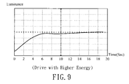
- FIG. 9 shows the relation between restarting time and brightness of the CCFL using the inverter disclosed in the second embodiment.
- FIG. 5 shows a temperature rising curve of a normal CCFL that is naturally warmed up.
- the horizontal X-axis is labeled in units of 5 seconds; the Y-axis shows the brightness.
- the invention finds a temperature lowering curve corresponding to the temperature rising curve. They are symmetric about the X axis. Since the sum of the temperature rising curve and the temperature lowering curve is a constant, we take the cross point of the two curves as a balance time.
- An energy storage circuit is designed accordingly so that the lighting load started by the disclosed inverter can rapidly reach stable illumination. Moreover, the stable illumination can be maintained after the lighting load is instantaneously disconnected and restarted. This is because the energy storage circuit can generate a lowering curve.
- FIG. 1 Please refer to FIG. 1 for a preferred embodiment of the invention. It includes an energy storage circuit, an oscillatory circuit, and a transformer.
- the light actuator has a power input terminal IN, a ground terminal GND, and output terminals OUT 1 , OUT 2 . Between the power input terminal IN and the connecting point A , there can be additionally designed capacitor or spike protection circuits for filtering or a switch that controls the light actuator.
- the energy storage circuit is connected between point A and point C. It is made of a voltage storage device C 3 and an impedance R 3 . According to a preferred embodiment, it is an RC circuit consisting of capacitors and resistors, such as the third capacitor C 3 and the third resistor R 3 shown in the drawing. The RC circuit is selected according to the temperature rising and temperature lowering curves of the lighting load; otherwise, the device cannot achieve the expected goal of rapid warmup. In addition, the energy storage circuit is connected with a first resistor R 1 in parallel.
- An oscillatory circuit is connected among points A, D, F, and G. It includes a first transistor Q 1 , a second transistor Q 2 , and a first capacitor C 1 .
- the base of the first transistor Q 1 connects to point C and one end of the coil NB.
- the other end of the coil NB connects to the base of the second transistor Q 2 .
- the common input point I of the coils NB 1 , NB 2 connects to point A so that power can be supplied through point I.
- the emitters of the first transistor Q 1 and the second transistor Q 2 connects to point E and the ground GND.
- the collector of the first transistor Q 1 connects to the other end of the coil NP 1 through point F.
- the collector of the second transistor Q 2 connects to the other end of the coil NP 2 .
- Both collectors connect to the first capacitor C 1 in parallel at points F and G.
- the coil NS of the output terminal connects to a second capacitor C 2 in series.
- the output terminal OUT 1 and OUT 2 connects to a lighting load M in parallel.
- the power is supplied to the base of the first transistor Q 1 via the input terminal IN.
- the voltage between points C and E varies. Therefore, the on and off of the first transistor Q 1 change with the pulse variation of the power input.
- the first transistor Q 1 and the second transistor Q 2 are disposed in a symmetric way, and so are the coil NP 1 and the coil NP 2 .
- the symmetry will be broken when the power supply sends in a high voltage. Consequently, the voltages on point F and point G are different.
- the input voltage is converted by the coils N 1 , NP 2 into an alternate output voltage. If the power supply sends a low voltage (usually 0), the work voltage or output voltage Vout is also zero because of the unbroken symmetry.
- the first transistor Q 1 and the second transistor Q 2 become a switch so that the input voltage is converted into the work voltage. Therefore, an output voltage Vout is obtained through the transformer conversion.
- the main function of the second capacitor C 2 is to stabilize the output voltage Vout.
- the first transistor Q 1 and the second transistor Q 2 continuously switch between on and off to output an oscillatory frequency.
- the energy stored in the energy storage circuit is immediately supplied to the transistors without delay. This can shorten the time for the lighting load M to reach its stable illumination.
- the light load M is off. Due to its properties, the lighting load M rapidly cools down. If the inverter restarts the lighting load M, it has to return to its original stable state. At this moment, the energy stored in the energy storage circuit does not disappear immediately because of the discontinuity of electrical power. Therefore, the stored energy can be quickly supplied to the transistors once the system restarts. The temperature of the lighting load M therefore does not drop too quickly.
- FIG. 2 shows a second embodiment of the disclosed inverter.
- the energy storage circuit is comprised of a fourth capacitor C 4 and a fourth resistor R 4 , connected in parallel with a third transistor Q 3 to amplify the voltage released from the fourth capacitor C 4 .
- the base of the third transistor Q 3 connects between the fourth capacitor C 4 and the fourth resistor R 4 .
- the collector connects to point A.
- the emitter connects to point D, the base of the second transistor Q 2 , via a second resistor R 2
- the operation principles of the second embodiment are the same as the first embodiment. The only difference is that the second embodiment can use a capacitor with a smaller capacitance and the voltage stored in the capacitor is amplified by a transistor.
- FIG. 3 Please refer to FIG. 3 for a third embodiment.
- a voltage-lowering device such as the MC34063 microprocessor, can be used along with the disclosed energy storage circuit.
- the energy storage circuit is comprised of the fifth resistor R 5 and the fifth capacitor C 5 , connected in parallel with necessary circuits such as the sixth resistor R 6 , a first diode D 1 , and a sixth capacitor C 6 .
- the fifth resistor R 5 is connected to a seventh resistor R 7 in series.
- the microprocessor U 1 can be an integrated circuit (IC) with eight pins. As shown in the drawing, a seventh capacitor C 7 is connected between the third pin and the ground GND. The fourth pin directly connects to the ground. The voltage input terminal connects to the sixth and eighth pins and couples to an eighth resistor R 8 . An eighth capacitor C 8 is coupled between the voltage input terminal and the ground terminal. The input voltage after the voltage drop is output via the second pin. The output voltage passes through a first inductor L 1 . Through the energy storage circuit made of the fifth resistor R 5 and the fifth capacitor C 5 , and the on and off of the first transistor Q 1 and the second transistor Q 2 , the lighting load M is started.
- IC integrated circuit
- a fourth embodiment of the invention is shown in FIG. 4 .
- one does not need the first transistor Q 1 and the second transistor Q 2 as the elements in the oscillatory circuit.
- a microprocessor U 1 is also used to provide an oscillatory frequency and voltage drop. It can again be an eight-pin IC with pins shown in the drawing.
- a seventh capacitor C 7 is connected between the third pin and the ground GND. The second and fourth pins directly connect to the ground.
- An eighth resistor R 8 and a ninth resistor R 9 are connected in series between the sixth and eights pins.
- the seventh pin is coupled between the eighth resistor R 8 and the ninth resistor R 9 .
- the fifth pin connects to the ground via the sixth resistor R 6 .
- a second inductor L 2 and a ninth capacitor C 9 are coupled between the voltage input terminal and the ground.
- the voltage is supplied between the second inductor L 2 and the ninth capacitor C 9 to the sixth pin of the microprocessor U 1 .
- the oscillatory frequency generated after the voltage drop is output via the first pin.
- the energy storage circuit is comprised of the fifth resistor R 5 and the fifth capacitor C 5 . It is connected in parallel with a sixth resistor R 6 and a sixth capacitor C 6 .
- a variable resistor RV 1 is connected between the sixth resistor R 6 and the sixth capacitor C 6 .
- the output energy is sent to point G via the second diode D 2 .
- Point I is connected between the eighth resistor R 8 and the ninth resistor R 9 .
- the transformer only needs two sets of first-order coils.
- the disclosed rapid warmup light actuator uses the CCFL as the lighting load to verify the feasibility of the invention.
- FIG. 6 shows a temperature rising curve of the CCFL using the disclosed inverter. Comparing the results of FIG. 5 and FIG. 6 , one finds that the disclosed inverter can greatly shorten the time to reach stable illumination. When using a 470 ⁇ F capacitor and a 2.7K resistor, only 9 seconds are needed. Therefore, a scanning device using the invention can be quickly started without wasting too much to wait.
- FIG. 7 shows the relation between the restarting time and brightness when using the inverter in the prior art. It is obvious that the brightness rapidly drops when the circuit is suddenly shut down. However, as shown in FIG. 8 , the continuity in instantaneous shutdown is better once lighting load has been illuminating in a stable state.
- the relation between time and brightness is given in FIG. 9 .
- the stabilizing time is as short as six seconds.
Abstract
A rapid warmup light actuator is disclosed to solve the problems that the light actuator cannot rapidly warm up the lighting load in the prior art and that unstable light sources result from the rapid temperature drop if the light is instantaneously disconnected and restarted. The device consists of an energy storage circuit, an oscillatory circuit, and a transformer. In the beginning of power supply, the energy storage circuit is charged. When starting the lighting load, the energy stored in the energy storage circuit rapidly warms up the lighting load in order to illuminate stable light. Using the energy stored in the energy storage circuit, the lighting load can continue its stable status even it is instantaneously disconnected and restarted.
Description
This Non-provisional application claims priority under 35 U.S.C. § 119(a) on Patent Application No(s). 092125592 filed in Taiwan on Sep. 17, 2003, the entire contents of which are hereby incorporated by reference.
1. Field of Invention
The invention relates to a light actuator and, in particular, to a light actuator that can rapidly warm up a lighting load and keep it illuminating in a stable way.
2. Related Art
The cold cathode fluorescent lamp (CCFL) has wide applications. For example, it is used as the backlit source of liquid crystal display (LCD) screens, in scanners, and in multiple function peripherals (MFP). Other applications such as the transparent media adaptor (TMA), the scan of negative film or XPA also use the CCFL as the light source.
Since the CCFL requires an extremely high voltage (about several hundred volts) when it is started and working, the driving device or inverter has to be able provide such a high-voltage output. The output power quality of the driving device determines the lighting quality and stability of the CCFL.
To ensure the quality of the light source, the temperature of the CCFL has to reach a certain temperature. Therefore, normal scanners have to spend some time to warm up the CCFL after it is turned on. This is why the CCFL of many existing scanners requires a warmup time of about three minutes. In colder areas or environments, the warmup time may be even longer.
Therefore, methods for rapidly warming up the CCFL have been proposed. For example, in the U.S. Pat. No. 5,907,742 uses a dual input voltage control method. That means a higher input voltage (about 12V) is used to make the temperature of the CCFL quickly rise to its work temperature. A lower input voltage (about 8V) is then used after the warmup. Although the method can reduce the CCFL's warmup time down to about 30 seconds, it nevertheless makes the CCFL to sustain a higher current during the warmup time, thereby resulting in a shorter lifetime.
Secondly, to have two different input voltages (for warmup and work times), it uses a pulse width modulation control circuit to control the input voltage. Their circuit design is more complicated.
Moreover, the above-mentioned patent uses the frequency oscillator built in the inverter. The oscillatory frequency often drifts randomly between 35 and 45 kHz under different voltages and temperatures. Consequently, the lighting may become unstable and thus affect the scanning quality.
Another rapid warmup method is to install a NiCr wire coiling around the CCFL. Using the heat generated by the NiCr wire, the lamp tube is forced to raise its temperature. Although this method can achieve the goal of rapidly warming up the CCFL, the addition of the NiCr wire complicates the manufacturing process. Secondly, the NiCr wire also increases the cost, including the equipment and power consumption. The most serious problem is the light blocking by the heating wire around the lamp tube. Therefore, the light intensity of the CCFL is inhomogeneous and affects the scanning quality. Furthermore, the NiCr wire is fragile and thus increases the maintenance cost.
Therefore, current methods of rapidly warming up the CCFL have their own limitations and problems. It is an important subject of the field how to rapidly warm up the CCFL at the same time elongating its lifetime and maintaining a stable light source.
In view of the foregoing problems, an objective of the invention is to provide a rapid warmup light actuator. The disclosed light actuator designs a temperature lowering curve according to the natural warmup curve of the lighting load to be started. Using the rising and lowering curves, an energy storage circuit and the oscillatory circuit in the light actuator are designed to reduce the time for the lighting load to become a stable light source. When the light is instantaneously turned off and restarted, it can continue sending out stable light.
To achieve the above objective, the disclosed rapid warmup light actuator has an energy storage circuit, an oscillatory circuit, and a transformer. In the beginning of the power supply, the energy storage circuit is charged so that the energy stored in the energy storage circuit rapidly warms up the lighting load for stable illumination.
The invention will become more fully understood from the detailed description given hereinbelow illustration only, and thus are not limitative of the present invention, and wherein:
We first explain the main idea of the invention. We take the CCFL of a lighting load as an example. FIG. 5 shows a temperature rising curve of a normal CCFL that is naturally warmed up. The horizontal X-axis is labeled in units of 5 seconds; the Y-axis shows the brightness. One sees from the plots that it takes about 50 seconds for the lighting load to reach its stable illumination. The invention finds a temperature lowering curve corresponding to the temperature rising curve. They are symmetric about the X axis. Since the sum of the temperature rising curve and the temperature lowering curve is a constant, we take the cross point of the two curves as a balance time. An energy storage circuit is designed accordingly so that the lighting load started by the disclosed inverter can rapidly reach stable illumination. Moreover, the stable illumination can be maintained after the lighting load is instantaneously disconnected and restarted. This is because the energy storage circuit can generate a lowering curve.
Please refer to FIG. 1 for a preferred embodiment of the invention. It includes an energy storage circuit, an oscillatory circuit, and a transformer. The light actuator has a power input terminal IN, a ground terminal GND, and output terminals OUT1, OUT2. Between the power input terminal IN and the connecting point A , there can be additionally designed capacitor or spike protection circuits for filtering or a switch that controls the light actuator.
The energy storage circuit is connected between point A and point C. It is made of a voltage storage device C3 and an impedance R3. According to a preferred embodiment, it is an RC circuit consisting of capacitors and resistors, such as the third capacitor C3 and the third resistor R3 shown in the drawing. The RC circuit is selected according to the temperature rising and temperature lowering curves of the lighting load; otherwise, the device cannot achieve the expected goal of rapid warmup. In addition, the energy storage circuit is connected with a first resistor R1 in parallel.
An oscillatory circuit is connected among points A, D, F, and G. It includes a first transistor Q1, a second transistor Q2, and a first capacitor C1. The base of the first transistor Q1 connects to point C and one end of the coil NB. The other end of the coil NB connects to the base of the second transistor Q2. The common input point I of the coils NB1, NB2 connects to point A so that power can be supplied through point I. The emitters of the first transistor Q1 and the second transistor Q2 connects to point E and the ground GND. The collector of the first transistor Q1 connects to the other end of the coil NP1 through point F. The collector of the second transistor Q2 connects to the other end of the coil NP2. Both collectors connect to the first capacitor C1 in parallel at points F and G. The coil NS of the output terminal connects to a second capacitor C2 in series. The output terminal OUT1 and OUT2 connects to a lighting load M in parallel. The power is supplied to the base of the first transistor Q1 via the input terminal IN. The voltage between points C and E varies. Therefore, the on and off of the first transistor Q1 change with the pulse variation of the power input. The first transistor Q1 and the second transistor Q2 are disposed in a symmetric way, and so are the coil NP1 and the coil NP2. The symmetry will be broken when the power supply sends in a high voltage. Consequently, the voltages on point F and point G are different. The input voltage is converted by the coils N1, NP2 into an alternate output voltage. If the power supply sends a low voltage (usually 0), the work voltage or output voltage Vout is also zero because of the unbroken symmetry.
When the power supply sends a voltage to point C, the first transistor Q1 and the second transistor Q2 become a switch so that the input voltage is converted into the work voltage. Therefore, an output voltage Vout is obtained through the transformer conversion. The main function of the second capacitor C2 is to stabilize the output voltage Vout. In the following paragraphs, we describe the operation principles of the invention. Before the inclusion of the energy storage device, when the power is supplied from the input terminal, the oscillatory frequency output by the oscillatory circuit composed of the first transistor Q1 and the second transistor Q2 is converted by the transformer made of the coils NP1, NP2, NB, and NS into an appropriate output voltage. In this case, the lighting load M is started. Under this circuit structure, the lighting load requires a longer time to illuminate in a stable way.
Once the energy storage circuit (composed of the third resistor R3 and the third capacitor C3), the first transistor Q1 and the second transistor Q2 continuously switch between on and off to output an oscillatory frequency. The energy stored in the energy storage circuit is immediately supplied to the transistors without delay. This can shorten the time for the lighting load M to reach its stable illumination. When the circuit is instantaneously shut down, the light load M is off. Due to its properties, the lighting load M rapidly cools down. If the inverter restarts the lighting load M, it has to return to its original stable state. At this moment, the energy stored in the energy storage circuit does not disappear immediately because of the discontinuity of electrical power. Therefore, the stored energy can be quickly supplied to the transistors once the system restarts. The temperature of the lighting load M therefore does not drop too quickly.
The operation principles of the second embodiment are the same as the first embodiment. The only difference is that the second embodiment can use a capacitor with a smaller capacitance and the voltage stored in the capacitor is amplified by a transistor.
Please refer to FIG. 3 for a third embodiment. Consider the situation when the input voltage is higher and the inverter needs a lower voltage. For example, when the input voltage is over 24V while the inverter only requires a 12V input. In this case, one can use the inverter disclosed here. As shown in the drawing, a voltage-lowering device, such as the MC34063 microprocessor, can be used along with the disclosed energy storage circuit. The energy storage circuit is comprised of the fifth resistor R5 and the fifth capacitor C5, connected in parallel with necessary circuits such as the sixth resistor R6, a first diode D1, and a sixth capacitor C6. The fifth resistor R5 is connected to a seventh resistor R7 in series. One end of the fifth capacitor C5 connects to the ground GND. The microprocessor U1 can be an integrated circuit (IC) with eight pins. As shown in the drawing, a seventh capacitor C7 is connected between the third pin and the ground GND. The fourth pin directly connects to the ground. The voltage input terminal connects to the sixth and eighth pins and couples to an eighth resistor R8. An eighth capacitor C8 is coupled between the voltage input terminal and the ground terminal. The input voltage after the voltage drop is output via the second pin. The output voltage passes through a first inductor L1. Through the energy storage circuit made of the fifth resistor R5 and the fifth capacitor C5, and the on and off of the first transistor Q1 and the second transistor Q2, the lighting load M is started.
A fourth embodiment of the invention is shown in FIG. 4 . In this embodiment, one does not need the first transistor Q1 and the second transistor Q2 as the elements in the oscillatory circuit. A microprocessor U1 is also used to provide an oscillatory frequency and voltage drop. It can again be an eight-pin IC with pins shown in the drawing. A seventh capacitor C7 is connected between the third pin and the ground GND. The second and fourth pins directly connect to the ground. An eighth resistor R8 and a ninth resistor R9 are connected in series between the sixth and eights pins. The seventh pin is coupled between the eighth resistor R8 and the ninth resistor R9. The fifth pin connects to the ground via the sixth resistor R6. A second inductor L2 and a ninth capacitor C9 are coupled between the voltage input terminal and the ground. The voltage is supplied between the second inductor L2 and the ninth capacitor C9 to the sixth pin of the microprocessor U1. The oscillatory frequency generated after the voltage drop is output via the first pin.
The energy storage circuit is comprised of the fifth resistor R5 and the fifth capacitor C5. It is connected in parallel with a sixth resistor R6 and a sixth capacitor C6. A variable resistor RV1 is connected between the sixth resistor R6 and the sixth capacitor C6. The output energy is sent to point G via the second diode D2. Point I is connected between the eighth resistor R8 and the ninth resistor R9. In the fourth embodiment, the transformer only needs two sets of first-order coils.
The disclosed rapid warmup light actuator uses the CCFL as the lighting load to verify the feasibility of the invention. FIG. 6 shows a temperature rising curve of the CCFL using the disclosed inverter. Comparing the results of FIG. 5 and FIG. 6 , one finds that the disclosed inverter can greatly shorten the time to reach stable illumination. When using a 470 μF capacitor and a 2.7K resistor, only 9 seconds are needed. Therefore, a scanning device using the invention can be quickly started without wasting too much to wait.
As to the continuous performance, please refer to FIG. 7 and FIG. 8 . FIG. 7 shows the relation between the restarting time and brightness when using the inverter in the prior art. It is obvious that the brightness rapidly drops when the circuit is suddenly shut down. However, as shown in FIG. 8 , the continuity in instantaneous shutdown is better once lighting load has been illuminating in a stable state.
For the second embodiment of the invention, the relation between time and brightness is given in FIG. 9 . We see that the stabilizing time is as short as six seconds.
Certain variations would be apparent to those skilled in the art, which variations are considered within the spirit and scope of the claimed invention.
Claims (17)
1. A light actuator for starting a lighting load, which comprises:
an oscillatory circuit, which outputs an oscillatory frequency from a direct current (DC) power;
a transformer, which connects to the oscillatory circuit in parallel and output an alternate current (AC) voltage to drive the lighting load at the oscillatory frequency;
an energy storage circuit, which is connected in series between the oscillatory circuit and the power input terminal for storing energy and for using the stored energy to maintain stable illumination of the lighting load when the light actuator starts to restarts after an instantaneous shutdown.
2. The light actuator of claim 1 , wherein the energy storage circuit further comprises a voltage storage device and an impedance device connected in series.
3. The light actuator of claim 1 , wherein the energy stored in the energy storage circuit is determined by the temperature rising curve of the lighting load.
4. The light actuator of claim 1 further comprising a third transistor connected in parallel with the energy storage circuit.
5. The light actuator of claim 1 , wherein the oscillatory circuit further comprises a first transistor and a second transistor connected in series.
6. The light actuator of claim 4 , wherein the oscillatory circuit further comprises a capacitor connected in parallel with the first transistor and the second transistor.
7. The light actuator of claim 1 , wherein the output terminal of the transformer is connected in series with a capacitor.
8. A light actuator for starting a lighting load, which comprises:
a microprocessor, which drops the voltage of an input voltage;
an energy storage circuit, which is coupled to the microprocessor for storing the lowered input voltage;
an oscillatory circuit, which outputs an oscillatory frequency according to the lowered input voltage; and
a transformer, which is connected to the oscillatory circuit in parallel to output an AC voltage according to the oscillatory frequency for driving the lighting load;
wherein the energy stored in the energy storage circuit keeps the lighting load illuminate in a stable way when the lighting load is started/restarted.
9. The light actuator of claim 8 , wherein the energy storage circuit further includes a voltage storage device and an impedance device connected in series.
10. The light actuator of claim 8 , wherein the energy stored in the energy storage circuit is determined by the temperature rising curve of the lighting load.
11. The light actuator of claim 8 , wherein the oscillatory circuit further comprises a first transistor and a second transistor connected in series.
12. The light actuator of claim 11 , wherein the oscillatory circuit further comprises a capacitor connected in parallel with the first transistor and the second transistor.
13. The light actuator of claim 8 , wherein the output terminal of the transformer is connected in series with a capacitor.
14. A light actuator for starting a lighting load, which comprises:
a microprocessor, which sends out an oscillatory frequency and an output voltage according to an input voltage;
an energy storage circuit, which is coupled to the microprocessor for storing the output voltage;
a transformer, which is connected to the microprocessor to output an AC voltage according to the oscillatory frequency for driving the lighting load;
wherein the energy stored in the energy storage circuit keeps the lighting load illuminate in a stable way when the lighting load is started/restarted.
15. The light actuator of claim 14 , wherein the energy storage circuit further includes a voltage storage device and an impedance device connected in series.
16. The light actuator of claim 14 , wherein the energy stored in the energy storage circuit is determined by the temperature rising curve of the lighting load.
17. The light actuator of claim 14 , wherein the output terminal of the transformer is connected in series with a capacitor.
Priority Applications (1)
| Application Number | Priority Date | Filing Date | Title |
|---|---|---|---|
| CA 2471927 CA2471927A1 (en) | 2004-06-08 | 2004-06-30 | Drill |
Applications Claiming Priority (2)
| Application Number | Priority Date | Filing Date | Title |
|---|---|---|---|
| TW092125592A TWI220853B (en) | 2003-09-17 | 2003-09-17 | Quick warm-up lighting device |
| TW092125592 | 2003-09-17 |
Publications (2)
| Publication Number | Publication Date |
|---|---|
| US20050057163A1 US20050057163A1 (en) | 2005-03-17 |
| US7057357B2 true US7057357B2 (en) | 2006-06-06 |
Family
ID=34114743
Family Applications (1)
| Application Number | Title | Priority Date | Filing Date |
|---|---|---|---|
| US10/862,354 Expired - Fee Related US7057357B2 (en) | 2003-09-17 | 2004-06-08 | Rapid warmup light actuator |
Country Status (2)
| Country | Link |
|---|---|
| US (1) | US7057357B2 (en) |
| TW (1) | TWI220853B (en) |
Cited By (1)
| Publication number | Priority date | Publication date | Assignee | Title |
|---|---|---|---|---|
| US20090002776A1 (en) * | 2007-06-27 | 2009-01-01 | Samsung Electronics Co., Ltd | Image scanning apparatus and method thereof |
Citations (7)
| Publication number | Priority date | Publication date | Assignee | Title |
|---|---|---|---|---|
| US5581158A (en) * | 1989-09-21 | 1996-12-03 | Etta Industries, Inc. | Lamp brightness control circuit with ambient light compensation |
| US5770925A (en) * | 1997-05-30 | 1998-06-23 | Motorola Inc. | Electronic ballast with inverter protection and relamping circuits |
| US5907742A (en) | 1997-03-09 | 1999-05-25 | Hewlett-Packard Company | Lamp control scheme for rapid warmup of fluorescent lamp in office equipment |
| US6281636B1 (en) * | 1997-04-22 | 2001-08-28 | Nippo Electric Co., Ltd. | Neutral-point inverter |
| US6429603B1 (en) * | 1999-04-28 | 2002-08-06 | Mitsubishi Denki Kabushiki Kaisha | Discharge lamp lighting apparatus |
| US6853155B2 (en) * | 2002-03-11 | 2005-02-08 | Denso Corporation | Electric discharge lamp device |
| US6906473B2 (en) * | 2003-08-26 | 2005-06-14 | Osram Sylvania Inc. | Feedback circuit and method of operating ballast resonant inverter |
-
2003
- 2003-09-17 TW TW092125592A patent/TWI220853B/en not_active IP Right Cessation
-
2004
- 2004-06-08 US US10/862,354 patent/US7057357B2/en not_active Expired - Fee Related
Patent Citations (7)
| Publication number | Priority date | Publication date | Assignee | Title |
|---|---|---|---|---|
| US5581158A (en) * | 1989-09-21 | 1996-12-03 | Etta Industries, Inc. | Lamp brightness control circuit with ambient light compensation |
| US5907742A (en) | 1997-03-09 | 1999-05-25 | Hewlett-Packard Company | Lamp control scheme for rapid warmup of fluorescent lamp in office equipment |
| US6281636B1 (en) * | 1997-04-22 | 2001-08-28 | Nippo Electric Co., Ltd. | Neutral-point inverter |
| US5770925A (en) * | 1997-05-30 | 1998-06-23 | Motorola Inc. | Electronic ballast with inverter protection and relamping circuits |
| US6429603B1 (en) * | 1999-04-28 | 2002-08-06 | Mitsubishi Denki Kabushiki Kaisha | Discharge lamp lighting apparatus |
| US6853155B2 (en) * | 2002-03-11 | 2005-02-08 | Denso Corporation | Electric discharge lamp device |
| US6906473B2 (en) * | 2003-08-26 | 2005-06-14 | Osram Sylvania Inc. | Feedback circuit and method of operating ballast resonant inverter |
Cited By (2)
| Publication number | Priority date | Publication date | Assignee | Title |
|---|---|---|---|---|
| US20090002776A1 (en) * | 2007-06-27 | 2009-01-01 | Samsung Electronics Co., Ltd | Image scanning apparatus and method thereof |
| US8373913B2 (en) * | 2007-06-27 | 2013-02-12 | Samsung Electronics Co., Ltd. | Image scanning apparatus and method thereof |
Also Published As
| Publication number | Publication date |
|---|---|
| TW200513150A (en) | 2005-04-01 |
| US20050057163A1 (en) | 2005-03-17 |
| TWI220853B (en) | 2004-09-01 |
Similar Documents
| Publication | Publication Date | Title |
|---|---|---|
| EP1814367B1 (en) | Backlight inverter and its driving method | |
| CN100423438C (en) | DC-AC transformer and controller IC thereof | |
| US7215087B2 (en) | Discharge lamp lighting apparatus for lighting multiple discharge lamps | |
| JP2006245005A (en) | Lamp coupling structure capable of driving in parallel | |
| EP1566991A1 (en) | Discharge lamp driving apparatus | |
| JP2002203689A (en) | Driving device and driving method of cold cathode fluorescent tube using piezoelectric transformer | |
| TW200411620A (en) | Inverter apparatus and liquid crystal display including inverter apparatus | |
| US7235931B2 (en) | Discharge lamp lighting apparatus for lighting multiple discharge lamps | |
| US7230390B2 (en) | Cold cathode fluorescent lamp assembly | |
| CN101507366A (en) | High voltage discharge lamp lighting apparatus and illuminating equipment | |
| CN100558212C (en) | The driving lamp of liquid crystal display device and driving method | |
| TW556445B (en) | Discharge lamp apparatus and driving apparatus for discharge lamp | |
| US7057357B2 (en) | Rapid warmup light actuator | |
| KR100463093B1 (en) | Apparatus and method for driving a cathode discharge tube | |
| JP2981993B2 (en) | Liquid crystal backlight lighting device and liquid crystal display device | |
| KR20040042849A (en) | Device for operating discharge lamps | |
| US7298093B2 (en) | Method and device for driving CCFL circuit | |
| JP4966055B2 (en) | Discharge lamp lighting device, illumination device using the same, and liquid crystal display device | |
| KR101777566B1 (en) | LED Lamp | |
| US6703797B2 (en) | Method for activating illuminator and illumination device | |
| CN220106005U (en) | Display backlight control circuit, circuit board, display screen and television | |
| JP4690296B2 (en) | Discharge lamp lighting device | |
| JPH04233193A (en) | Electroluminescence (el)element driving circuit | |
| JP4703626B2 (en) | Discharge lamp lighting device | |
| JP4442241B2 (en) | Discharge lamp lighting device and lighting apparatus using the same |
Legal Events
| Date | Code | Title | Description |
|---|---|---|---|
| AS | Assignment |
Owner name: LITE-ON TECHNOLOGY CORPORATION, TAIWAN Free format text: ASSIGNMENT OF ASSIGNORS INTEREST;ASSIGNOR:CHANG, CHING-CHUNG;REEL/FRAME:015444/0355 Effective date: 20040501 |
|
| FPAY | Fee payment |
Year of fee payment: 4 |
|
| REMI | Maintenance fee reminder mailed | ||
| LAPS | Lapse for failure to pay maintenance fees | ||
| STCH | Information on status: patent discontinuation |
Free format text: PATENT EXPIRED DUE TO NONPAYMENT OF MAINTENANCE FEES UNDER 37 CFR 1.362 |
|
| FP | Lapsed due to failure to pay maintenance fee |
Effective date: 20140606 |