US7057442B2 - Temperature-independent current source circuit - Google Patents
Temperature-independent current source circuit Download PDFInfo
- Publication number
- US7057442B2 US7057442B2 US10/833,693 US83369304A US7057442B2 US 7057442 B2 US7057442 B2 US 7057442B2 US 83369304 A US83369304 A US 83369304A US 7057442 B2 US7057442 B2 US 7057442B2
- Authority
- US
- United States
- Prior art keywords
- current
- transistor
- terminal
- temperature
- current source
- Prior art date
- Legal status (The legal status is an assumption and is not a legal conclusion. Google has not performed a legal analysis and makes no representation as to the accuracy of the status listed.)
- Active, expires
Links
Images


Classifications
-
- G—PHYSICS
- G05—CONTROLLING; REGULATING
- G05F—SYSTEMS FOR REGULATING ELECTRIC OR MAGNETIC VARIABLES
- G05F1/00—Automatic systems in which deviations of an electric quantity from one or more predetermined values are detected at the output of the system and fed back to a device within the system to restore the detected quantity to its predetermined value or values, i.e. retroactive systems
- G05F1/10—Regulating voltage or current
- G05F1/46—Regulating voltage or current wherein the variable actually regulated by the final control device is dc
- G05F1/52—Regulating voltage or current wherein the variable actually regulated by the final control device is dc using discharge tubes in series with the load as final control devices
-
- G—PHYSICS
- G05—CONTROLLING; REGULATING
- G05F—SYSTEMS FOR REGULATING ELECTRIC OR MAGNETIC VARIABLES
- G05F3/00—Non-retroactive systems for regulating electric variables by using an uncontrolled element, or an uncontrolled combination of elements, such element or such combination having self-regulating properties
- G05F3/02—Regulating voltage or current
- G05F3/08—Regulating voltage or current wherein the variable is dc
- G05F3/10—Regulating voltage or current wherein the variable is dc using uncontrolled devices with non-linear characteristics
- G05F3/16—Regulating voltage or current wherein the variable is dc using uncontrolled devices with non-linear characteristics being semiconductor devices
- G05F3/20—Regulating voltage or current wherein the variable is dc using uncontrolled devices with non-linear characteristics being semiconductor devices using diode- transistor combinations
- G05F3/26—Current mirrors
- G05F3/265—Current mirrors using bipolar transistors only
Definitions
- the present invention relates to current sources. More specifically, the present invention relates to a temperature-independent current source circuits.
- Exisiting circuits are illustrated in FIGS. 1( a ) and 1 ( b ), showing a PTAT (proportional to absolute temperature) current source and an NTAT (inversely proportional to absolute temperature) current source.
- a PTAT source includes two transistors Q 1 and Q 2 , a resistor R 1 , and a current mirror.
- the collector currents of transistors Q 1 and Q 2 are essentially the same when the current ratio of the current mirror is equal to one. Values of the collector currents are given:
- IPTAT is a value that corresponds to the collector current of the transistor
- N is a ratio of the emitter area of the transistors Q 1 and Q 2
- q is the absolute value of the charge of an electron
- k is Boltzmann's constant
- T is the absolute temperature.
- a current source that outputs a current that is inversely proportional to the absolute temperature T includes two transistors Q 3 and Q 4 , a resistor R 2 , and a current mirror 10 .
- Current mirror 10 of FIG. 1( b ) has the same function as that of the current mirror of FIG. 1( a ). Since the ratio of the input and output of the current mirror is essentially one, the values of the collector currents of transistors Q 3 and Q 4 are the same. This collector current value is determined by transistor Q 3 and resistor R 2 :
- INTAT is the collector current of transistors Q 3 and Q 4 and VBE is a base-emitter voltage of transistor Q 3 , which can be a bipolar transistor. Since VBE decreases as the temperature increases, VBE is reduced by about ⁇ 2 mV when a junction temperature is increased by about 1 degree. Accordingly, the circuit of FIG. 1( b ) is an NTAT current source as described by Equation (2).
- the current sources of FIGS. 1( a ) and 1 ( b ) are influenced by the temperature.
- Temperature-independent current sources have been created in the past by combining a PTAT current source and an NTAT current source, as described in U.S. Pat. Nos. 6,310,510 and 6,023,185.
- U.S. Pat. No. 6,310,510 described a circuit functioning as an NTAT current source and a circuit functioning as a PTAT current source, and combined them into a temperature-independent current source, thereby requiring a lot of circuit elements, increasing the cost.
- This architecture also lowers the quality of the current source because of a problem of matching both circuits. This matching problem leads to an increased sensitivity of the output current to the temperature.
- U.S. Pat. No. 6,023,185 requires a band gap reference.
- Embodiments of the present invention include essentially temperature-independent high quality current sources, employing a simple circuit design.
- embodiments of the invention do not require a band gap reference.
- a current source includes: a first transistor having a first terminal for receiving a first current, and a grounded second terminal; a second transistor having a first terminal for outputting a predetermined part of a second current, a second terminal grounded through a first resistor, and a control terminal coupled to a control terminal of the first transistor.
- the current source further includes a third transistor having a first terminal coupled to the first terminal of the second transistor, for outputting a residual part of the second current, a second terminal coupled to the control terminal of the second transistor, and a control terminal coupled to the first terminal of the first transistor; and a second resistor coupled between the control terminal of the first and second transistors and the ground.
- An essentially temperature-independent current is generated at the output terminal of the current mirror by controlling a size ratio of the first and second transistors, and choosing the first and second resistors appropriately.
- a current source comprises: a first transistor having a first terminal for receiving a first current, and a second transistor having a control terminal coupled to a control terminal of the first transistor, a first terminal for outputting a predetermined part of a second current, and a second terminal grounded through a first resistor, wherein the first and second transistors and the first resistor generate a current that is proportional to the temperature at the first terminal of the second transistor.
- the current source further includes a third transistor having a control terminal coupled to the first terminal of the first transistor, a second terminal coupled to a control terminal of the first transistor, functioning as a buffer, and a first terminal coupled to the first terminal of the second transistor for outputting a residual part of the second current.
- first transistor and a second resistor that is coupled between the control terminal of the first transistor and the ground, generate a current that is inversely proportional to the temperature at the first terminal of the third transistor.
- this current source the first current and the second current are essentially independent of the temperature.
- a current source in still another aspect of the present invention, includes a first Darlington transistor having a first terminal for receiving a first current, a grounded second terminal, and a control terminal coupled to the first terminal, and a second Darlington transistor having a first terminal for outputting a second current, a second terminal grounded through a first resistor, and first and second control terminals respectively coupled to the first and second control terminals of the first Darlington transistor.
- FIG. 1( a ) shows a configuration of a conventional PTAT current source.
- FIG. 1( b ) shows a configuration of a conventional NTAT current source.
- FIG. 2 shows a configuration of a temperature-independent current source according to an embodiment of the invention.
- FIG. 3( a ) shows a dual base Darlington bipolar transistor included in a temperature-independent current source circuit according to an embodiment of the invention.
- FIG. 3( b ) shows a symbol diagram of the dual base Darlington bipolar transistor shown in FIG. 3( a ).
- FIG. 4 shows a configuration of a temperature-independent current source according to an embodiment of the invention.
- FIG. 5 shows a detailed diagram of FIG. 4 .
- FIGS. 6( a )–( c ) show a simulation of the temperature dependence of a current in an embodiment of the invention.
- FIG. 2 shows a configuration of a TI (temperature-independent) current source according to an embodiment of the invention.
- the TI current source comprises three transistors Q 10 , Q 20 , and Q 30 , two resistors R 10 and R 20 , and a current mirror 100 for mirroring an input current from an input port to an output port.
- the current ratio of the input current and the output current is approximately one.
- transistors Q 10 and Q 20 are coupled and the base and the emitter of transistor Q 30 are coupled to the collector and the base of transistor Q 10 . Therefore, transistors Q 10 and Q 20 and resistor R 10 function as a PTAT current source, in analogy to the one described in relation to FIG. 1( a ).
- transistors Q 10 and Q 30 and resistor R 20 function as the NTAT current source described in relation to FIG. 1( b ).
- One of the functions of transistor Q 30 is to be a buffer for the circuit-part that produces the PTAT current source.
- Another function is to provide a predetermined part of the NTAT current for the circuit-part that functions as the NTAT current source.
- the collector current INTAT of transistor Q 30 from the part that produces the NTAT current source is given by Equation (2).
- the TI (temperature independent) current source includes the combination of the circuit-part that functions as the PTAT current source and the circuit-part that functions as the NTAT current source.
- the collector currents of transistors Q 20 and Q 30 are the currents of the PTAT current source and the NTAT current source, respectively.
- the currents INTAT and IPTAT of the NTAT and PTAT current sources are combined and the combined current is mirrored to the collector of transistor Q 10 by current mirror 100 .
- the mirrored collector current of transistor Q 10 is an essentially temperature independent current.
- ITI is the current of the TI current source
- IPTAT and INTAT are the currents of the PTAT and NTAT current sources, respectively.
- the temperature independence of ITI can be seen by performing partial differentiation on Equation (3) with respect to the temperature:
- VT R1 ⁇ ln ⁇ ⁇ N ⁇ T 300 ⁇ ⁇ K ⁇ ⁇ ( 1 VBE ⁇ ⁇ V
- IPTAT the value of the IPTAT at room temperature of 300K is denoted as IPTAT,0.
- Equation (4) Substituting the expressions from Equations (5) to (9) into Equation (4) gives a final form for the temperature derivative of the ITI current with respect to the temperature. If this derivative is zero, then ITI is independent of the temperature.
- IPTAT , 0 INTAT , 0 TC , R - TC , VBE TC , VT - TC , R ( 11 )
- Equation (10) the ratio of the sizes of transistors Q 10 and Q 20 , N, and the values of the resistors R 10 and R 20 are found to satisfy Equation (10).
- Temperature-independent current sources can be implemented by using simple circuits depicted in FIG. 2 .
- temperature dependencies of the parameters of transistors Q 10 , Q 20 , and 30 are different, and hence, it is difficult to find a value N that satisfies Equation (10), and to find suitable values of resistors R 10 and R 20 .
- FIGS. 3–5 illustrate temperature independent current sources according to embodiments of the invention.
- FIG. 3( a ) shows a DB2T (dual-base Darlington bipolar transistor) included in a temperature-independent current source circuit.
- FIG. 3( b ) illustrates a symbol of the DB2T shown in FIG. 3( a ).
- the DB2T comprises two transistors Q 50 and Q 60 , and a resistor R 50 .
- the collectors of transistors Q 50 and Q 60 are coupled, the emitter of transistor Q 50 is coupled to the base B 2 of transistor Q 60 , and resistor Q 50 is coupled to the base B 2 of transistor Q 60 .
- a function of transistor Q 50 is to generate a NTAT current
- a function of transistor Q 60 is to generate a PTAT current
- Resistor R 50 and the VBE (a voltage of the base with respect to the emitter) value of transistor Q 60 determine the amount of the INTAT.
- the DB2T has two parameters, which include an emitter size (referred to as SIZE,Q 50 hereinafter) of transistor Q 50 and an emitter size (referred to as SIZE,Q 60 hereinafter) of transistor Q 60 .
- the parameter SIZE,Q 60 is greater than the parameter SIZE,Q 50 .
- FIG. 4 illustrates another current source according to an embodiment of the invention.
- the temperature-independent current source comprises two DB2Ts: DQ 1 and DQ 2 , a resistor R 60 , and current mirror 100 .
- DQ 1 , DQ 2 , resistor R 60 , and current mirror 100 have similar functions as those described in relation to FIGS. 2 and 3 .
- the collector of DQ 1 is coupled to the first base B 1 of DQ 2
- the two bases B 1 and B 2 of DQ 1 are respectively coupled to the two bases B 1 and B 2 of DQ 2
- resistor R 60 is coupled between the emitter of DQ 1 and the ground.
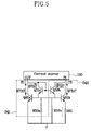
- FIG. 5 shows a diagram of FIG. 4 in some detail.
- Transistor Q 60 a in DQ 1 , transistor Q 60 b in DQ 2 , the coupled second bases of DQ 1 and DQ 2 , and resistor R 60 function as the PTAT current source.
- the size of the emitter of DQ 2 is N times larger than that of the other transistors as shown in FIG. 4 .
- the N-times size difference and the value of the resistor R 60 determines the IPTAT current.
- the INTAT current is determined by the values of resistors R 50 a and R 50 b and the respective VBE values of transistors Q 50 a and Q 50 b.
- IPTAT the current of the temperature-independent current source, as shown by Equation (3).
- the values of resistors R 60 , R 50 a , and R 50 b , and the value of N are chosen so that Equation (10) is satisfied. With this choice of parameters the circuit of FIG. 5 describes a temperature-independent current source.
- FIGS. 6( a )–( c ) show the results of a simulation of the temperature dependence of the currents INTAT, IPTAT and ITI.
- FIG. 6( a ) displays INTAT as a function of the temperature
- FIG. 6( b ) shows IPTAT
- FIG. 6( c ) shows ITI as a function of the temperature in the range of ⁇ 40 degree to 150 degree.
- FIG. 6( a ) shows that INTAT is inversely proportional to the temperature.
- FIG. 6( b ) shows that IPTAT is proportional to the temperature.
- FIG. 6( c ) illustrates that ITI exhibits a variation of 0.63% in the temperature range of ⁇ 40 degree and 150 degree. This value of the ITI variation is lower than that of existing circuits.
- NPN bipolar junction transistors were described in some embodiments, but corresponding circuits with PNP transistors, SiGe BJTs, or HBTs can also be used. Further, equivalent circuits utilizing MOS transistors, biased in the weak inversion region can be used as well.
- An aspect of the invention is that the circuit-part that functions as the NTAT current source and the circuit-part that functions as the PTAT current source are realized in an integrated manner, without realizing each circuit separately and then combining them. This aspect is partially responsible for the current source having a simpler circuit, yet exhibiting an improved performance.
Abstract
Description
ITI=IPTAT+INTAT (3)
where the value of INTAT at room temperature of 300K is denoted as INTAT,0.
Claims (7)
Priority Applications (1)
| Application Number | Priority Date | Filing Date | Title |
|---|---|---|---|
| US11/447,586 US7453314B2 (en) | 2003-05-23 | 2006-06-05 | Temperature-independent current source circuit |
Applications Claiming Priority (2)
| Application Number | Priority Date | Filing Date | Title |
|---|---|---|---|
| KR1020030032911A KR101072611B1 (en) | 2003-05-23 | 2003-05-23 | Temperature Independent Current Source Circuit |
| KR10-2003-0032911 | 2003-05-23 |
Related Child Applications (1)
| Application Number | Title | Priority Date | Filing Date |
|---|---|---|---|
| US11/447,586 Division US7453314B2 (en) | 2003-05-23 | 2006-06-05 | Temperature-independent current source circuit |
Publications (2)
| Publication Number | Publication Date |
|---|---|
| US20040232976A1 US20040232976A1 (en) | 2004-11-25 |
| US7057442B2 true US7057442B2 (en) | 2006-06-06 |
Family
ID=33448221
Family Applications (2)
| Application Number | Title | Priority Date | Filing Date |
|---|---|---|---|
| US10/833,693 Active 2024-06-07 US7057442B2 (en) | 2003-05-23 | 2004-04-28 | Temperature-independent current source circuit |
| US11/447,586 Expired - Lifetime US7453314B2 (en) | 2003-05-23 | 2006-06-05 | Temperature-independent current source circuit |
Family Applications After (1)
| Application Number | Title | Priority Date | Filing Date |
|---|---|---|---|
| US11/447,586 Expired - Lifetime US7453314B2 (en) | 2003-05-23 | 2006-06-05 | Temperature-independent current source circuit |
Country Status (2)
| Country | Link |
|---|---|
| US (2) | US7057442B2 (en) |
| KR (1) | KR101072611B1 (en) |
Cited By (5)
| Publication number | Priority date | Publication date | Assignee | Title |
|---|---|---|---|---|
| US20050122139A1 (en) * | 2003-12-08 | 2005-06-09 | Isao Yamamoto | Current drive circuit reducing VDS dependency |
| US20060220733A1 (en) * | 2003-05-23 | 2006-10-05 | Fairchild Korea Semiconductor Ltd. | Temperature-independent current source circuit |
| US7230472B1 (en) * | 2005-10-11 | 2007-06-12 | National Semiconductor Corporation | Base current cancellation for bipolar junction transistor current summing bias voltage generator |
| US20100166035A1 (en) * | 2008-12-30 | 2010-07-01 | Jang-Hyun Yoon | Temperature measuring device |
| US20110158286A1 (en) * | 2008-11-18 | 2011-06-30 | Peterson Luverne R | Digital output temperature sensor and method of temperature sensing |
Families Citing this family (6)
| Publication number | Priority date | Publication date | Assignee | Title |
|---|---|---|---|---|
| DE102004002423B4 (en) * | 2004-01-16 | 2015-12-03 | Infineon Technologies Ag | Bandgap reference circuit |
| US7250806B2 (en) * | 2005-03-02 | 2007-07-31 | Avago Technologies Ecbu Ip (Singapore) Pte. Ltd. | Apparatus and method for generating an output signal that tracks the temperature coefficient of a light source |
| US7688112B2 (en) * | 2006-12-13 | 2010-03-30 | Advanced Science & Novel Technology | Anti-SEE protection techniques for high-speed ICs with a current-switching architecture |
| TWI470394B (en) * | 2012-12-13 | 2015-01-21 | Issc Technologies Corp | Voltage generator |
| CN107515639B (en) * | 2017-08-25 | 2018-11-23 | 电子科技大学 | A kind of circuit for generating source voltage of Low Drift Temperature |
| KR102293671B1 (en) * | 2017-11-29 | 2021-08-24 | 삼성전자주식회사 | Apparatus for testing semiconductor device method tof testing semiconductor device |
Citations (3)
| Publication number | Priority date | Publication date | Assignee | Title |
|---|---|---|---|---|
| US4467289A (en) * | 1979-11-05 | 1984-08-21 | Sony Corporation | Current mirror circuit |
| US4687984A (en) * | 1984-05-31 | 1987-08-18 | Precision Monolithics, Inc. | JFET active load input stage |
| US5675243A (en) * | 1995-05-31 | 1997-10-07 | Motorola, Inc. | Voltage source device for low-voltage operation |
Family Cites Families (4)
| Publication number | Priority date | Publication date | Assignee | Title |
|---|---|---|---|---|
| US4639684A (en) * | 1984-11-06 | 1987-01-27 | Harris Corporation | Differential input stage for the realization of low noise and high precision bipolar transistor amplifiers |
| US5859568A (en) * | 1997-04-11 | 1999-01-12 | Raytheon Company | Temperature compensated amplifier |
| JP2002116831A (en) | 2000-10-05 | 2002-04-19 | Sharp Corp | Constant current generating circuit |
| KR101072611B1 (en) * | 2003-05-23 | 2011-10-11 | 페어차일드코리아반도체 주식회사 | Temperature Independent Current Source Circuit |
-
2003
- 2003-05-23 KR KR1020030032911A patent/KR101072611B1/en active IP Right Grant
-
2004
- 2004-04-28 US US10/833,693 patent/US7057442B2/en active Active
-
2006
- 2006-06-05 US US11/447,586 patent/US7453314B2/en not_active Expired - Lifetime
Patent Citations (3)
| Publication number | Priority date | Publication date | Assignee | Title |
|---|---|---|---|---|
| US4467289A (en) * | 1979-11-05 | 1984-08-21 | Sony Corporation | Current mirror circuit |
| US4687984A (en) * | 1984-05-31 | 1987-08-18 | Precision Monolithics, Inc. | JFET active load input stage |
| US5675243A (en) * | 1995-05-31 | 1997-10-07 | Motorola, Inc. | Voltage source device for low-voltage operation |
Cited By (12)
| Publication number | Priority date | Publication date | Assignee | Title |
|---|---|---|---|---|
| US20060220733A1 (en) * | 2003-05-23 | 2006-10-05 | Fairchild Korea Semiconductor Ltd. | Temperature-independent current source circuit |
| US7453314B2 (en) | 2003-05-23 | 2008-11-18 | Fairchild Korea Semiconductor, Ltd. | Temperature-independent current source circuit |
| US20050122139A1 (en) * | 2003-12-08 | 2005-06-09 | Isao Yamamoto | Current drive circuit reducing VDS dependency |
| US7230474B2 (en) * | 2003-12-08 | 2007-06-12 | Rohm Co., Ltd. | Current drive circuit reducing VDS dependency |
| US20070205812A1 (en) * | 2003-12-08 | 2007-09-06 | Isao Yamamoto | Current drive circuit reducing VDS dependency |
| US7372322B2 (en) | 2003-12-08 | 2008-05-13 | Rohm Co., Ltd. | Current drive circuit reducing VDS dependency |
| US20080169870A1 (en) * | 2003-12-08 | 2008-07-17 | Rohm Co., Ltd. | Current drive circuit reducing vds dependency |
| US7479822B2 (en) | 2003-12-08 | 2009-01-20 | Rohm Co., Ltd. | Current drive circuit reducing VDS dependency |
| US7230472B1 (en) * | 2005-10-11 | 2007-06-12 | National Semiconductor Corporation | Base current cancellation for bipolar junction transistor current summing bias voltage generator |
| US20110158286A1 (en) * | 2008-11-18 | 2011-06-30 | Peterson Luverne R | Digital output temperature sensor and method of temperature sensing |
| US8596864B2 (en) * | 2008-11-18 | 2013-12-03 | Toshiba America Electronic Components, Inc. | Digital output temperature sensor and method of temperature sensing |
| US20100166035A1 (en) * | 2008-12-30 | 2010-07-01 | Jang-Hyun Yoon | Temperature measuring device |
Also Published As
| Publication number | Publication date |
|---|---|
| US7453314B2 (en) | 2008-11-18 |
| KR20040100522A (en) | 2004-12-02 |
| KR101072611B1 (en) | 2011-10-11 |
| US20060220733A1 (en) | 2006-10-05 |
| US20040232976A1 (en) | 2004-11-25 |
Similar Documents
| Publication | Publication Date | Title |
|---|---|---|
| US7453314B2 (en) | Temperature-independent current source circuit | |
| US5926062A (en) | Reference voltage generating circuit | |
| JP2682470B2 (en) | Reference current circuit | |
| US7173481B2 (en) | CMOS reference voltage circuit | |
| US7511568B2 (en) | Reference voltage circuit | |
| US6987416B2 (en) | Low-voltage curvature-compensated bandgap reference | |
| US6351111B1 (en) | Circuits and methods for providing a current reference with a controlled temperature coefficient using a series composite resistor | |
| US7053694B2 (en) | Band-gap circuit with high power supply rejection ratio | |
| EP0601540A1 (en) | Reference voltage generator of a band-gap regulator type used in CMOS transistor circuit | |
| US6426669B1 (en) | Low voltage bandgap reference circuit | |
| US20080265860A1 (en) | Low voltage bandgap reference source | |
| JP3039611B2 (en) | Current mirror circuit | |
| US4308496A (en) | Reference current source circuit | |
| US6342781B1 (en) | Circuits and methods for providing a bandgap voltage reference using composite resistors | |
| US6288525B1 (en) | Merged NPN and PNP transistor stack for low noise and low supply voltage bandgap | |
| US20030001660A1 (en) | Temperature-dependent reference generator | |
| JPH08272468A (en) | Reference voltage generation circuit | |
| CN105574228A (en) | Circuit and method for compensating for early effects | |
| US20140152290A1 (en) | Reference voltage circuit | |
| US20070069709A1 (en) | Band gap reference voltage generator for low power | |
| KR19990007418A (en) | Constant current circuit | |
| JP2581492B2 (en) | Input buffer circuit | |
| JPH0228165B2 (en) | ||
| US11480989B2 (en) | High accuracy zener based voltage reference circuit | |
| US6310519B1 (en) | Method and apparatus for amplifier output biasing for improved overall temperature stability |
Legal Events
| Date | Code | Title | Description |
|---|---|---|---|
| AS | Assignment |
Owner name: FAIRCHILD KOREA SEMICONDUCTOR, LTD., KOREA, REPUBL Free format text: ASSIGNMENT OF ASSIGNORS INTEREST;ASSIGNORS:HWANG, JONG-TAE;KIM, DONG-HWAN;LEE, YUN-KEE;REEL/FRAME:017642/0499 Effective date: 20060417 |
|
| STCF | Information on status: patent grant |
Free format text: PATENTED CASE |
|
| FEPP | Fee payment procedure |
Free format text: PAYOR NUMBER ASSIGNED (ORIGINAL EVENT CODE: ASPN); ENTITY STATUS OF PATENT OWNER: LARGE ENTITY |
|
| FPAY | Fee payment |
Year of fee payment: 4 |
|
| FPAY | Fee payment |
Year of fee payment: 8 |
|
| AS | Assignment |
Owner name: SEMICONDUCTOR COMPONENTS INDUSTRIES, LLC, ARIZONA Free format text: ASSIGNMENT OF ASSIGNORS INTEREST;ASSIGNOR:FAIRCHILD KOREA SEMICONDUCTOR, LTD.;REEL/FRAME:044361/0205 Effective date: 20171102 |
|
| MAFP | Maintenance fee payment |
Free format text: PAYMENT OF MAINTENANCE FEE, 12TH YEAR, LARGE ENTITY (ORIGINAL EVENT CODE: M1553) Year of fee payment: 12 |
|
| AS | Assignment |
Owner name: DEUTSCHE BANK AG NEW YORK BRANCH, AS COLLATERAL AGENT, NEW YORK Free format text: PATENT SECURITY AGREEMENT;ASSIGNORS:SEMICONDUCTOR COMPONENTS INDUSTRIES, LLC;FAIRCHILD SEMICONDUCTOR CORPORATION;REEL/FRAME:046530/0460 Effective date: 20171110 Owner name: DEUTSCHE BANK AG NEW YORK BRANCH, AS COLLATERAL AG Free format text: PATENT SECURITY AGREEMENT;ASSIGNORS:SEMICONDUCTOR COMPONENTS INDUSTRIES, LLC;FAIRCHILD SEMICONDUCTOR CORPORATION;REEL/FRAME:046530/0460 Effective date: 20171110 |
|
| AS | Assignment |
Owner name: FAIRCHILD SEMICONDUCTOR CORPORATION, ARIZONA Free format text: RELEASE OF SECURITY INTEREST IN PATENTS RECORDED AT REEL 046530, FRAME 0460;ASSIGNOR:DEUTSCHE BANK AG NEW YORK BRANCH, AS COLLATERAL AGENT;REEL/FRAME:064075/0001 Effective date: 20230622 Owner name: SEMICONDUCTOR COMPONENTS INDUSTRIES, LLC, ARIZONA Free format text: RELEASE OF SECURITY INTEREST IN PATENTS RECORDED AT REEL 046530, FRAME 0460;ASSIGNOR:DEUTSCHE BANK AG NEW YORK BRANCH, AS COLLATERAL AGENT;REEL/FRAME:064075/0001 Effective date: 20230622 |