US7074610B2 - System and method of microdispensing and arrays of biolayers provided by same - Google Patents
System and method of microdispensing and arrays of biolayers provided by same Download PDFInfo
- Publication number
- US7074610B2 US7074610B2 US09/941,661 US94166101A US7074610B2 US 7074610 B2 US7074610 B2 US 7074610B2 US 94166101 A US94166101 A US 94166101A US 7074610 B2 US7074610 B2 US 7074610B2
- Authority
- US
- United States
- Prior art keywords
- array
- layer
- wafer
- sensor
- enzyme
- Prior art date
- Legal status (The legal status is an assumption and is not a legal conclusion. Google has not performed a legal analysis and makes no representation as to the accuracy of the status listed.)
- Expired - Fee Related, expires
Links
- QAGJIINHZCXXLM-UHFFFAOYSA-N C=CCNC(=O)CC(O)(CC(=O)NCC=C)C(=O)NCC=C Chemical compound C=CCNC(=O)CC(O)(CC(=O)NCC=C)C(=O)NCC=C QAGJIINHZCXXLM-UHFFFAOYSA-N 0.000 description 2
- 0 *OC1CNC2=CC=CC=C21.O.OC1CNC2=CC=CC=C21 Chemical compound *OC1CNC2=CC=CC=C21.O.OC1CNC2=CC=CC=C21 0.000 description 1
- NLHHRLWOUZZQLW-UHFFFAOYSA-N C=CC#N Chemical compound C=CC#N NLHHRLWOUZZQLW-UHFFFAOYSA-N 0.000 description 1
- PDTPPOGRMPEBFS-UHFFFAOYSA-N C=CC(=O)CCOC(=O)C=C Chemical compound C=CC(=O)CCOC(=O)C=C PDTPPOGRMPEBFS-UHFFFAOYSA-N 0.000 description 1
- HFBMWMNUJJDEQZ-UHFFFAOYSA-N C=CC(=O)Cl Chemical compound C=CC(=O)Cl HFBMWMNUJJDEQZ-UHFFFAOYSA-N 0.000 description 1
- BEBLKGACCOKESH-UHFFFAOYSA-N C=CC(=O)N1CCC(CCC2CCN(C(=O)C=C)CC2)CC1 Chemical compound C=CC(=O)N1CCC(CCC2CCN(C(=O)C=C)CC2)CC1 BEBLKGACCOKESH-UHFFFAOYSA-N 0.000 description 1
- YERHJBPPDGHCRJ-UHFFFAOYSA-N C=CC(=O)N1CCN(C(=O)C=C)CC1 Chemical compound C=CC(=O)N1CCN(C(=O)C=C)CC1 YERHJBPPDGHCRJ-UHFFFAOYSA-N 0.000 description 1
- ZMLXKXHICXTSDM-UHFFFAOYSA-N C=CC(=O)NC(O)C(O)NC(=O)C=C Chemical compound C=CC(=O)NC(O)C(O)NC(=O)C=C ZMLXKXHICXTSDM-UHFFFAOYSA-N 0.000 description 1
- PCFWWFDIAGJLCX-UHFFFAOYSA-N C=CC(=O)NC.C=CC(N)=O Chemical compound C=CC(=O)NC.C=CC(N)=O PCFWWFDIAGJLCX-UHFFFAOYSA-N 0.000 description 1
- JDQOXPIFVWUPNN-UHFFFAOYSA-N C=CC(=O)NCC(=O)CNC(=O)C=C Chemical compound C=CC(=O)NCC(=O)CNC(=O)C=C JDQOXPIFVWUPNN-UHFFFAOYSA-N 0.000 description 1
- OXTCFMNURZMJFQ-UHFFFAOYSA-N C=CC(=O)NCC(C)(C)CNC(=O)C=C Chemical compound C=CC(=O)NCC(C)(C)CNC(=O)C=C OXTCFMNURZMJFQ-UHFFFAOYSA-N 0.000 description 1
- YTMJJBYCQDTILJ-UHFFFAOYSA-N C=CC(=O)NCC(C)(C)NC(=O)C=C Chemical compound C=CC(=O)NCC(C)(C)NC(=O)C=C YTMJJBYCQDTILJ-UHFFFAOYSA-N 0.000 description 1
- DJVKJGIZQFBFGS-UHFFFAOYSA-N C=CC(=O)NCCSSCCNC(=O)C=C Chemical compound C=CC(=O)NCCSSCCNC(=O)C=C DJVKJGIZQFBFGS-UHFFFAOYSA-N 0.000 description 1
- NIXOWILDQLNWCW-UHFFFAOYSA-N C=CC(=O)O Chemical compound C=CC(=O)O NIXOWILDQLNWCW-UHFFFAOYSA-N 0.000 description 1
- KUDUQBURMYMBIJ-UHFFFAOYSA-N C=CC(=O)OCCOC(=O)C=C Chemical compound C=CC(=O)OCCOC(=O)C=C KUDUQBURMYMBIJ-UHFFFAOYSA-N 0.000 description 1
- HRPVXLWXLXDGHG-UHFFFAOYSA-N C=CC(N)=O Chemical compound C=CC(N)=O HRPVXLWXLXDGHG-UHFFFAOYSA-N 0.000 description 1
- OBWGMYALGNDUNM-UHFFFAOYSA-N C=CC(OC)OC Chemical compound C=CC(OC)OC OBWGMYALGNDUNM-UHFFFAOYSA-N 0.000 description 1
- UTGFOWQYZKTZTN-UHFFFAOYSA-N C=CCC(O)CC=C Chemical compound C=CCC(O)CC=C UTGFOWQYZKTZTN-UHFFFAOYSA-N 0.000 description 1
- ZRKLEAHGBNDKHM-UHFFFAOYSA-N C=CCNC(=O)C(O)C(O)C(=O)NCC=C Chemical compound C=CCNC(=O)C(O)C(O)C(=O)NCC=C ZRKLEAHGBNDKHM-UHFFFAOYSA-N 0.000 description 1
- CLJFDRKGHKJAKZ-UHFFFAOYSA-N N.N.O.O=[C+]O Chemical compound N.N.O.O=[C+]O CLJFDRKGHKJAKZ-UHFFFAOYSA-N 0.000 description 1
- MYMOFIZGZYHOMD-UHFFFAOYSA-N O.O=O.[OH3+] Chemical compound O.O=O.[OH3+] MYMOFIZGZYHOMD-UHFFFAOYSA-N 0.000 description 1
- HGINCPLSRVDWNT-UHFFFAOYSA-N [H]C(=O)C=C Chemical compound [H]C(=O)C=C HGINCPLSRVDWNT-UHFFFAOYSA-N 0.000 description 1
Images


Classifications
-
- B—PERFORMING OPERATIONS; TRANSPORTING
- B01—PHYSICAL OR CHEMICAL PROCESSES OR APPARATUS IN GENERAL
- B01L—CHEMICAL OR PHYSICAL LABORATORY APPARATUS FOR GENERAL USE
- B01L3/00—Containers or dishes for laboratory use, e.g. laboratory glassware; Droppers
- B01L3/50—Containers for the purpose of retaining a material to be analysed, e.g. test tubes
- B01L3/502—Containers for the purpose of retaining a material to be analysed, e.g. test tubes with fluid transport, e.g. in multi-compartment structures
- B01L3/5027—Containers for the purpose of retaining a material to be analysed, e.g. test tubes with fluid transport, e.g. in multi-compartment structures by integrated microfluidic structures, i.e. dimensions of channels and chambers are such that surface tension forces are important, e.g. lab-on-a-chip
-
- B—PERFORMING OPERATIONS; TRANSPORTING
- B01—PHYSICAL OR CHEMICAL PROCESSES OR APPARATUS IN GENERAL
- B01L—CHEMICAL OR PHYSICAL LABORATORY APPARATUS FOR GENERAL USE
- B01L3/00—Containers or dishes for laboratory use, e.g. laboratory glassware; Droppers
- B01L3/02—Burettes; Pipettes
- B01L3/0241—Drop counters; Drop formers
- B01L3/0268—Drop counters; Drop formers using pulse dispensing or spraying, eg. inkjet type, piezo actuated ejection of droplets from capillaries
-
- B—PERFORMING OPERATIONS; TRANSPORTING
- B01—PHYSICAL OR CHEMICAL PROCESSES OR APPARATUS IN GENERAL
- B01L—CHEMICAL OR PHYSICAL LABORATORY APPARATUS FOR GENERAL USE
- B01L3/00—Containers or dishes for laboratory use, e.g. laboratory glassware; Droppers
- B01L3/50—Containers for the purpose of retaining a material to be analysed, e.g. test tubes
- B01L3/502—Containers for the purpose of retaining a material to be analysed, e.g. test tubes with fluid transport, e.g. in multi-compartment structures
- B01L3/5027—Containers for the purpose of retaining a material to be analysed, e.g. test tubes with fluid transport, e.g. in multi-compartment structures by integrated microfluidic structures, i.e. dimensions of channels and chambers are such that surface tension forces are important, e.g. lab-on-a-chip
- B01L3/502707—Containers for the purpose of retaining a material to be analysed, e.g. test tubes with fluid transport, e.g. in multi-compartment structures by integrated microfluidic structures, i.e. dimensions of channels and chambers are such that surface tension forces are important, e.g. lab-on-a-chip characterised by the manufacture of the container or its components
-
- B—PERFORMING OPERATIONS; TRANSPORTING
- B01—PHYSICAL OR CHEMICAL PROCESSES OR APPARATUS IN GENERAL
- B01L—CHEMICAL OR PHYSICAL LABORATORY APPARATUS FOR GENERAL USE
- B01L3/00—Containers or dishes for laboratory use, e.g. laboratory glassware; Droppers
- B01L3/50—Containers for the purpose of retaining a material to be analysed, e.g. test tubes
- B01L3/508—Containers for the purpose of retaining a material to be analysed, e.g. test tubes rigid containers not provided for above
- B01L3/5088—Containers for the purpose of retaining a material to be analysed, e.g. test tubes rigid containers not provided for above confining liquids at a location by surface tension, e.g. virtual wells on plates, wires
-
- C—CHEMISTRY; METALLURGY
- C12—BIOCHEMISTRY; BEER; SPIRITS; WINE; VINEGAR; MICROBIOLOGY; ENZYMOLOGY; MUTATION OR GENETIC ENGINEERING
- C12Q—MEASURING OR TESTING PROCESSES INVOLVING ENZYMES, NUCLEIC ACIDS OR MICROORGANISMS; COMPOSITIONS OR TEST PAPERS THEREFOR; PROCESSES OF PREPARING SUCH COMPOSITIONS; CONDITION-RESPONSIVE CONTROL IN MICROBIOLOGICAL OR ENZYMOLOGICAL PROCESSES
- C12Q1/00—Measuring or testing processes involving enzymes, nucleic acids or microorganisms; Compositions therefor; Processes of preparing such compositions
- C12Q1/001—Enzyme electrodes
-
- G—PHYSICS
- G01—MEASURING; TESTING
- G01N—INVESTIGATING OR ANALYSING MATERIALS BY DETERMINING THEIR CHEMICAL OR PHYSICAL PROPERTIES
- G01N33/00—Investigating or analysing materials by specific methods not covered by groups G01N1/00 - G01N31/00
- G01N33/48—Biological material, e.g. blood, urine; Haemocytometers
- G01N33/50—Chemical analysis of biological material, e.g. blood, urine; Testing involving biospecific ligand binding methods; Immunological testing
- G01N33/53—Immunoassay; Biospecific binding assay; Materials therefor
- G01N33/543—Immunoassay; Biospecific binding assay; Materials therefor with an insoluble carrier for immobilising immunochemicals
- G01N33/54366—Apparatus specially adapted for solid-phase testing
- G01N33/54373—Apparatus specially adapted for solid-phase testing involving physiochemical end-point determination, e.g. wave-guides, FETS, gratings
- G01N33/5438—Electrodes
-
- G—PHYSICS
- G01—MEASURING; TESTING
- G01N—INVESTIGATING OR ANALYSING MATERIALS BY DETERMINING THEIR CHEMICAL OR PHYSICAL PROPERTIES
- G01N35/00—Automatic analysis not limited to methods or materials provided for in any single one of groups G01N1/00 - G01N33/00; Handling materials therefor
- G01N35/0099—Automatic analysis not limited to methods or materials provided for in any single one of groups G01N1/00 - G01N33/00; Handling materials therefor comprising robots or similar manipulators
-
- B—PERFORMING OPERATIONS; TRANSPORTING
- B01—PHYSICAL OR CHEMICAL PROCESSES OR APPARATUS IN GENERAL
- B01L—CHEMICAL OR PHYSICAL LABORATORY APPARATUS FOR GENERAL USE
- B01L2200/00—Solutions for specific problems relating to chemical or physical laboratory apparatus
- B01L2200/12—Specific details about manufacturing devices
-
- B—PERFORMING OPERATIONS; TRANSPORTING
- B01—PHYSICAL OR CHEMICAL PROCESSES OR APPARATUS IN GENERAL
- B01L—CHEMICAL OR PHYSICAL LABORATORY APPARATUS FOR GENERAL USE
- B01L2300/00—Additional constructional details
- B01L2300/06—Auxiliary integrated devices, integrated components
- B01L2300/0627—Sensor or part of a sensor is integrated
- B01L2300/0636—Integrated biosensor, microarrays
-
- B—PERFORMING OPERATIONS; TRANSPORTING
- B01—PHYSICAL OR CHEMICAL PROCESSES OR APPARATUS IN GENERAL
- B01L—CHEMICAL OR PHYSICAL LABORATORY APPARATUS FOR GENERAL USE
- B01L2300/00—Additional constructional details
- B01L2300/06—Auxiliary integrated devices, integrated components
- B01L2300/0627—Sensor or part of a sensor is integrated
- B01L2300/0645—Electrodes
-
- B—PERFORMING OPERATIONS; TRANSPORTING
- B01—PHYSICAL OR CHEMICAL PROCESSES OR APPARATUS IN GENERAL
- B01L—CHEMICAL OR PHYSICAL LABORATORY APPARATUS FOR GENERAL USE
- B01L2300/00—Additional constructional details
- B01L2300/08—Geometry, shape and general structure
- B01L2300/0809—Geometry, shape and general structure rectangular shaped
- B01L2300/0819—Microarrays; Biochips
-
- B—PERFORMING OPERATIONS; TRANSPORTING
- B01—PHYSICAL OR CHEMICAL PROCESSES OR APPARATUS IN GENERAL
- B01L—CHEMICAL OR PHYSICAL LABORATORY APPARATUS FOR GENERAL USE
- B01L2300/00—Additional constructional details
- B01L2300/08—Geometry, shape and general structure
- B01L2300/089—Virtual walls for guiding liquids
-
- G—PHYSICS
- G01—MEASURING; TESTING
- G01N—INVESTIGATING OR ANALYSING MATERIALS BY DETERMINING THEIR CHEMICAL OR PHYSICAL PROPERTIES
- G01N35/00—Automatic analysis not limited to methods or materials provided for in any single one of groups G01N1/00 - G01N33/00; Handling materials therefor
- G01N35/00029—Automatic analysis not limited to methods or materials provided for in any single one of groups G01N1/00 - G01N33/00; Handling materials therefor provided with flat sample substrates, e.g. slides
- G01N2035/00039—Transport arrangements specific to flat sample substrates, e.g. pusher blade
- G01N2035/00059—Transport arrangements specific to flat sample substrates, e.g. pusher blade vacuum chucks
-
- G—PHYSICS
- G01—MEASURING; TESTING
- G01N—INVESTIGATING OR ANALYSING MATERIALS BY DETERMINING THEIR CHEMICAL OR PHYSICAL PROPERTIES
- G01N35/00—Automatic analysis not limited to methods or materials provided for in any single one of groups G01N1/00 - G01N33/00; Handling materials therefor
- G01N2035/00178—Special arrangements of analysers
- G01N2035/00237—Handling microquantities of analyte, e.g. microvalves, capillary networks
-
- G—PHYSICS
- G01—MEASURING; TESTING
- G01N—INVESTIGATING OR ANALYSING MATERIALS BY DETERMINING THEIR CHEMICAL OR PHYSICAL PROPERTIES
- G01N35/00—Automatic analysis not limited to methods or materials provided for in any single one of groups G01N1/00 - G01N33/00; Handling materials therefor
- G01N2035/00346—Heating or cooling arrangements
- G01N2035/00455—Controlling humidity in analyser
-
- G—PHYSICS
- G01—MEASURING; TESTING
- G01N—INVESTIGATING OR ANALYSING MATERIALS BY DETERMINING THEIR CHEMICAL OR PHYSICAL PROPERTIES
- G01N35/00—Automatic analysis not limited to methods or materials provided for in any single one of groups G01N1/00 - G01N33/00; Handling materials therefor
- G01N2035/00465—Separating and mixing arrangements
- G01N2035/00534—Mixing by a special element, e.g. stirrer
-
- G—PHYSICS
- G01—MEASURING; TESTING
- G01N—INVESTIGATING OR ANALYSING MATERIALS BY DETERMINING THEIR CHEMICAL OR PHYSICAL PROPERTIES
- G01N35/00—Automatic analysis not limited to methods or materials provided for in any single one of groups G01N1/00 - G01N33/00; Handling materials therefor
- G01N35/10—Devices for transferring samples or any liquids to, in, or from, the analysis apparatus, e.g. suction devices, injection devices
- G01N2035/1027—General features of the devices
- G01N2035/1034—Transferring microquantities of liquid
-
- G—PHYSICS
- G01—MEASURING; TESTING
- G01N—INVESTIGATING OR ANALYSING MATERIALS BY DETERMINING THEIR CHEMICAL OR PHYSICAL PROPERTIES
- G01N35/00—Automatic analysis not limited to methods or materials provided for in any single one of groups G01N1/00 - G01N33/00; Handling materials therefor
- G01N35/10—Devices for transferring samples or any liquids to, in, or from, the analysis apparatus, e.g. suction devices, injection devices
- G01N35/1065—Multiple transfer devices
- G01N2035/1076—Multiple transfer devices plurality or independently movable heads
-
- G—PHYSICS
- G01—MEASURING; TESTING
- G01N—INVESTIGATING OR ANALYSING MATERIALS BY DETERMINING THEIR CHEMICAL OR PHYSICAL PROPERTIES
- G01N35/00—Automatic analysis not limited to methods or materials provided for in any single one of groups G01N1/00 - G01N33/00; Handling materials therefor
- G01N35/10—Devices for transferring samples or any liquids to, in, or from, the analysis apparatus, e.g. suction devices, injection devices
- G01N35/1081—Devices for transferring samples or any liquids to, in, or from, the analysis apparatus, e.g. suction devices, injection devices characterised by the means for relatively moving the transfer device and the containers in an horizontal plane
- G01N35/109—Devices for transferring samples or any liquids to, in, or from, the analysis apparatus, e.g. suction devices, injection devices characterised by the means for relatively moving the transfer device and the containers in an horizontal plane with two horizontal degrees of freedom
-
- Y—GENERAL TAGGING OF NEW TECHNOLOGICAL DEVELOPMENTS; GENERAL TAGGING OF CROSS-SECTIONAL TECHNOLOGIES SPANNING OVER SEVERAL SECTIONS OF THE IPC; TECHNICAL SUBJECTS COVERED BY FORMER USPC CROSS-REFERENCE ART COLLECTIONS [XRACs] AND DIGESTS
- Y10—TECHNICAL SUBJECTS COVERED BY FORMER USPC
- Y10S—TECHNICAL SUBJECTS COVERED BY FORMER USPC CROSS-REFERENCE ART COLLECTIONS [XRACs] AND DIGESTS
- Y10S435/00—Chemistry: molecular biology and microbiology
- Y10S435/81—Packaged device or kit
-
- Y—GENERAL TAGGING OF NEW TECHNOLOGICAL DEVELOPMENTS; GENERAL TAGGING OF CROSS-SECTIONAL TECHNOLOGIES SPANNING OVER SEVERAL SECTIONS OF THE IPC; TECHNICAL SUBJECTS COVERED BY FORMER USPC CROSS-REFERENCE ART COLLECTIONS [XRACs] AND DIGESTS
- Y10—TECHNICAL SUBJECTS COVERED BY FORMER USPC
- Y10S—TECHNICAL SUBJECTS COVERED BY FORMER USPC CROSS-REFERENCE ART COLLECTIONS [XRACs] AND DIGESTS
- Y10S436/00—Chemistry: analytical and immunological testing
- Y10S436/807—Apparatus included in process claim, e.g. physical support structures
- Y10S436/809—Multifield plates or multicontainer arrays
Definitions
- This invention relates to wholly microfabricated biosensors, methods and materials for the mass production thereof, and their use in the determination of the presence and/or concentration of a variety of selected analyte species.
- the integrated biosensors of the present invention may be manufactured by a process which allows the incorporation of a variety of bioactive molecules, which bioactive molecules provide the basis of the analytical technique, through the use of materials which are compatible with the bioactive molecules and which materials have been especially adapted for that purpose.
- the integrated biosensors of the instant invention are also fully compatible with undiluted biological fluids and may be utilized in a wide range of medical, as well as nonmedical, applications.
- this invention relates to novel electrochemical assay procedures and to novel wholly microfabricated biosensors useful in determining the presence and/or concentration of biological species (analytes) of interest.
- the invention also relates to the novel use of a non-electroactive substrate (hereinafter the “substrate”) that does not undergo detectable oxidation or reduction at an electrode's operating potential, but which substrate undergoes a reaction with a substrate converter which gives rise to changes in the concentration of detectable electroactive species, these changes are measured and related to the concentration of the biological species of interest.
- the invention pertains to methods for the microfabrication of the biosensor.
- the assay procedures and biosensor of this invention are also exemplified as being useful in effecting immunoassays.
- immunoassays are also exemplified wherein the substrate converter is an enzyme (alkaline phosphatase) that reacts with the substrate (5-bromo-4-chloro-3-indoxyl phosphate) to produce changes in the concentration of electroactive species (dioxygen and hydrogen peroxide) which are electrochemically detected with the biosensor, an immunosensor in this instance.
- the substrate converter is an enzyme (alkaline phosphatase) that reacts with the substrate (5-bromo-4-chloro-3-indoxyl phosphate) to produce changes in the concentration of electroactive species (dioxygen and hydrogen peroxide) which are electrochemically detected with the biosensor, an immunosensor in this instance.
- electroactive species dioxygen and hydrogen peroxide
- one embodiment of the biosensor comprises a base sensor comprising a catalytic electrode and optional reference electrode, an adhesion promoter layer overlaid on the biosensor, and a bioactive layer that is covalently immobilized on the adhesion promoter layer, which bioactive layer is a receptor of the immunological analyte of interest.
- a layer containing the enzyme urease and an ammonium ion-selective electrode or an ammonia gas sensing electrode is known in the art.
- a recent example of such a diagnostic system is described by Conover, G., et al. in U.S. Pat. No. 4,713,165.
- a nitrocellulose membrane is immersed in a solution of the enzyme urease which is absorbed into the membrane.
- This enzyme-containing membrane in its dessicated state, is then mounted onto the surface of an ammonium ISE.
- the resulting macroelectrode device is used to perform a blood urea nitrogen (BUN) measurement in biological fluids, such as serum, plasma, blood, and the like.
- BUN blood urea nitrogen
- a urease layer is coated over a cation-sensitive electrode, which layer may comprise urease and gelatin, fibrin, or filter paper pulp.
- An outer semipermeable membrane made from collodion (a cellulosic material) or cellophane is common, also.
- a base sensor typically an electrode
- a planar surface such as a silicon wafer
- Such complex layers would contain relatively labile biological molecules such as ionophores, enzymes, antibodies, antigens or fragments thereof and are, in general, weak and sensitive to mechanical agitation.
- Such layers may be applied onto a wafer, preventing their inactivation and/or destruction due to further processing steps is not readily achieved because such processing commonly includes exposing the wafer to organic chemicals, strong acids and bases, heat, or subjecting the wafer to mechanical agitation, dicing, or scribing, usually accompanied by wash steps which employ low-pressure water-jets.
- European Patent Application No. 0 012 035 provides ample discussion regarding the deficiencies of current FET devices, foremost of which is their limited applicability to the analysis of nonionic species. In an attempt to combine electrochemistry and semiconductor technology, miniaturized multiple sensors are fabricated on a single chip. The utility of this reference is limited, however, because the disclosure only speaks in general terms and contains no enabling description of the critical biolayers and protective barriers which are critical to the successful microfabrication of functional biosensors. In fact, only materials such as cellulose and a poly(vinyl chloride) (PVC) layer containing valinomycin (sensitive to potassium ions) or nonactin (sensitive to ammonium ions) are specifically disclosed, and the deficiencies of these materials have been known in the biosensor art for sometime.
- PVC poly(vinyl chloride)
- Japanese Application No. 61-234349 describes a FET semiconductor biosensor coated with a solution of enzyme and a crosslinking agent to provide a crosslinked layer over the entire semiconductor. Separate applications of commonly used photoresist materials are then required to protect desired areas from a subsequent treatment of protease. Reliance on enzymatic digestion of undesired protein layers is expected to give unreliable and unsuitable dimensional control. Precise dimensional control is an important consideration in the mass production of microstructures. Japanese Application No.
- 61-283862 discloses a procedure for fixing an enzyme membrane by applying a polymer solution containing an enzyme on a solid surface, drying, applying a crosslinking agent to the resulting film through a mask, and removing noncrosslinked portions of said film. Again, such a technique fails to take advantage of standard photoresist technology and can only lead to a poorly resolved pattern.
- Japanese Application No. 61-254845 employs the typical approach of immersing sensor elements in enzyme-containing solutions and then selectively inactivating the membranes.
- photosensitive synthetic polymers to provide patterned membranes.
- glucose oxidase has been mixed with a photosensitive synthetic polymer mixture consisting of poly(vinyl pyrrolidone) (PVP) and 2,5-bis(4′-azo-2′-sulfobenzal)cyclopentanone (BASC) (See, Hanazato, Y. et al. Anal. Chim. Acta 1987, 193, 87; Hanazato, Y. et al. in European Patent Application No. 0 228 259).
- PVP poly(vinyl pyrrolidone)
- BASC 2,5-bis(4′-azo-2′-sulfobenzal)cyclopentanone
- a system similar to that described above has been devised for applying the enzymes glucose oxidase and urease onto adjacent ISFET gates using a photosensitive synthetic polymer consisting of poly(vinyl alcohol) (PVA) and styrylpyridinium or stilbazolium salt (see, Takatsu, I. and Moriizumi, T. in Sensors and Actuators 1987, 11, 309; Ichimura, K. U.S. Pat. No. 4,272,620). Also, Moriizumi, T. and Miyahara, Y. in Sensors and Actuators 1985, 7, 1 and in an article published in Proceedings, Int'l. Conf.
- PVA poly(vinyl alcohol)
- styrylpyridinium or stilbazolium salt see, Takatsu, I. and Moriizumi, T. in Sensors and Actuators 1987, 11, 309; Ichimura, K. U.S. Pat. No. 4,272,620.
- Published Japanese Patent Application No. 62-223557 discloses a means for manufacturing an array of different enzyme layers on an integrted ISFET device.
- a hydrophilic porous film is established over the gate on the ISFET and then an ink jet nozzle is used to deposit enzyme onto the film.
- This process utilizes spray type technology with the fluid drop being first electrically charged and then fired from the nozzle. In this system the nozzle, fluid drop, and substrate surface are never in a contiguous physical contact. The diameter of the drops range from 20 to 100 micrometers.
- published Japanese Patent Application No. 59-24244 discloses a similar membrane deposition process based on ink jet nozzle technology.
- ISFET devices are described in which various membrane compositions are deposited with the aid of a microsyringe. Again, a thick film resist polymer must be employed to delineate the area about the gate region of the ISFET device. In this manner, four types of membranes are applied and made separate from one another.
- the injected enzyme e.g., urease or glucose oxidase
- BSA glutaraldehyde
- silane coupling reagents especially those of the formula R′Si(OR) 3 in which R′ is typically an aliphatic group with a terminal amine and R is a lower alkyl group
- R′ is typically an aliphatic group with a terminal amine and R is a lower alkyl group
- a chemically modified platinum electrode has been described in which ⁇ -aminopropyltriethoxysilane and glutaraldehyde were used in a step-wise process to attach and to co-crosslink bovine serum albumin (BSA) and glucose oxidase (GOX) to the platinum surface (Yao, T. Analytica Chim. Acta 1983, 148, 27–33).
- BSA bovine serum albumin
- GOX glucose oxidase
- Fujihara and co-workers in J. Electroanalytical Chem. 1985, 195, 197–201, describes the use of a toluene solution of n-dodecyltriethoxysilane as a means for blocking the active sites of a catalytic gold electrode surface toward the reduction of hydrogen peroxide.
- the preparation of a permselective layer of variable thickness and its use to screen out undesired electroactive species while maintaining the high catalytic activity of the electrode surface are not disclosed or suggested.
- Japanese Patent Applications refer to the establishment of selective layers on non-microfabricated electrodes.
- Japanese Application No. 62-261952 describes the use of certain silane compounds, for the formation of a silicon layer which excludes the passage of uric and ascorbic acids but allows the permeation of hydrogen peroxide.
- Application No. JP 63-101743 pertains to a hydrogen peroxide permselective film which is derived from a high polymer film of poly(allylamine) crosslinked by the action of a suitable chemical agent. None of the references cited above discloses patterned permselective silane layers established on microfabricated devices.
- Particle latex materials and the distinct “film-forming” latices are old materials.
- Methods for producing film-forming latices by emulsion polymerization, their properties, and some of their uses have been reviewed (See, for example, Wagner and Fisher Kolloid Z. 1936, 77, 12; Vanderhoff, J. W. and Hwa, J. C. Polymer Symposia Wiley-Interscience, New York (1969)). Additional references include: Whitley, G. S. and Katz, M. K. Indust. Eng. Chem. 1933, 25, 1204–1211 and 1338–1348; Matsumoto, T. Emulsions and Emulsion Technology Vol. II , Lissant, K. J.
- This reference contains no teaching or suggestion that film-forming latices can be used as a medium containing anything other than an inorganic salt.
- Immunoassays are sensitive diagnostic tools for the in vitro detection of a variety of antigens or antibodies and their association with diseases or other significant physiological conditions.
- a polyclonal antibody preparation bound to a solid phase was used in heterogeneous assays whereby a solution of labeled antigen was allowed to compete directly with antigen in a sample to determine the extent of bound labeled antigen or to detect the extent of antigen present in the liquid phase. This method provided a way for measuring the presence and quantity of antigen in the sample being analyzed.
- the bound antibody is generally affixed to beads or small particles.
- the antibody can also be coated onto a surface.
- an incubation period is generally required of both the solid phase and labeled antibodies. A prolonged incubation period is particularly troublesome if results are needed quickly. Additionally, the long incubation periods and multiple washings have significantly limited the use of the assays to clinical laboratories, which have highly trained personnel and sophisticated equipment to undertake the assay. Consequently, there is presently a need for simpler and more rapid immunoassay protocols, and simpler apparatuses for use in emergency rooms, physicians' offices and even for in-home health care services.
- Ward Proc. Natl. Acad. Sci. USA 1983, 80(13), 4045) utilized bromo-chloro-indoxyl phosphate for visualizing biotin-labeled DNA probes hybridized to DNA or RNA immobilized onto nitrocellulose i.e., bioblots.
- S. J. Holt and P. W. Sadler Proc. Roy. Soc. B 1958, 148, 481) described the application of the conversion of indoxyl or a substituted indoxyl into the corresponding indigoid dye to cytochemical staining methods for the localization of cellular enzymes.
- Examples of other chromogenic applications of the oxidative conversion of indoxyl compounds to indigoid dye have included: an indigogenic reaction for alkaline and acid phosphatase histochemical demonstration in disk electrophoresis (E. Epstein, P. L. Wolf, J. P. Horwitz, and B. Zak in Am. J. Clin. Pathol. 1967, 48(5), 530); the comparison of simultaneous azo-dye coupling methods and an indigogenic reaction for alkaline phosphatase in polyacrylamide disc gels (T. F. Savage, E. C. Smith, and Collins in Stain Technol. 1972, 47 (2), 77); protein blotting principles and applications (J. M. Gershoni and G. E. Palade in Anal.
- electrochemical detection as an alternative to color detection is described in Anal. Chem. 1984 56, 2355.
- the reference discloses an assay in which an enzyme label converts an electroinactive compound to a detectable electroactive compound.
- the electroactive compound, phenol is oxidized at a potential of +750 mV.
- the method is not generally applicable since other electroactive components are present in blood or serum which are also oxidizable at this potential.
- the alcohol products resulting from the hydrolysis reaction catalyzed by the enzyme (i.e., phenol, p-nitrophenol, and p-aminophenol, respectively), themselves, are detected.
- the enzyme i.e., phenol, p-nitrophenol, and p-aminophenol, respectively.
- European Patent Applications Nos. 0247796 and 0270206 describe methods for conducting immunoassays which involve primarily moveable magnetic particles to which are bound immunoactive molecules. Enzyme conjugates are described which generate electroactive species such as H 2 O 2 . However, the principal means of detection involves chemiluminescence and, in any event, indoxyl compounds are not mentioned and no microfabricated sensing devices useful in performing immunoassays are disclosed.
- the present invention relates to wholly microfabricated biosensors and various processes for the mass microfabrication thereof.
- the microfabrication processes establish a plurality of thin films and related structures over a planar wafer in a fashion which allows exemplary reproducibility and control over the dimensional features of the overlaid structures.
- reproducibility and dimensional control have been realized at the wafer level for the mass production of chemical sensors, which sensors incorporate biologically active macromolecules and other reagents necessary for the conversion of selected analyte molecules to more readily detectable species.
- This invention also relates to novel electrochemical assay procedures and to novel wholly microfabricated biosensors useful in determining the presence and/or concentration of biological species (analytes) of interest.
- the invention also relates to the novel use of a substrate (hereinafter the “substrate”) that does not undergo detectable electrochemical oxidation or reduction but which undergoes a reaction with a substrate converter producing changes in the concentration of electroactive species. These changes are measured and related proportionately to the concentration of the analyte of interest. Additionally, the invention pertains to methods for making the biosensor.
- the assay procedures and biosensor of this invention are particularly exemplified as being useful in effecting immunoassays.
- immunoassays are also exemplified wherein the substrate convertor is an enzyme that hydrolyzes the substrate. This hydrolyzed substrate can then undergo reactions which produce changes in the concentration of electroactive species (dioxygen and hydrogen peroxide) which are electrochemically detected with the biosensor, a ligand/ligand receptor-based (LLR-based) biosensor in this instance.
- LLR-based ligand/ligand receptor-based
- one embodiment of the present biosensor comprises a catalytic electrode and optional reference electrode (base sensor), an adhesion promoter layer overlaid on the biosensor, and a bioactive layer that is immobilized on the adhesion promoter layer, which bioactive layer is a receptor (first member) of the immunological analyte of interest.
- the wholly microfabricated biosensor of the present invention comprises a substantially planar wafer on which a first structure comprising a suitable base sensor is established. Additional structures are then established over the resulting base sensor, which additional structures include a semipermeable solid film or permselective layer capable of acting as a barrier against interfering chemical species while allowing the transport of smaller detectable chemical moieties of interest. These detectable chemical moieties are typically electroactive molecules and may include low molecular weight ionic species.
- the semipermeable solid film may further comprise compounds or molecules which may serve to sensitize the base sensor to a preselected ionic species (e.g., ammonium ion).
- such permselective layers may also function as adhesion promoters by which the preselected ligand receptor may be immobilized to the wholly microfabricated LLR-based biosensor embodiment of the present invention.
- support matrices described in the instant invention which matrices possess the physical and chemical features necessary to support the various bioactive molecules that constitute the principal means for converting the particular analytes in a given analytical sample into detectable and/or quantitatively measureable species.
- Techniques are disclosed for localizing or patterning said matrices on certain desired areas of the wholly microfabricated biosensor which allow for the optimum control over dimensional features of the biolayers as well as the versatility to accommodate a wide range of bioactive molecules.
- the present invention also discloses materials which serve, in particular embodiments of the instant biosensor, as overlaid structures for the attenuation of the transport of selected analyte species which are present in high concentrations in the sample.
- Such analyte attenuation (AA) layers allow for a linear sensor response over a wider range of analyte concentrations than would be observed in the absence of an AA layer.
- the overlaid AA layer which is preferably derived from a siloxane/nonsiloxane copolymer, is capable of excluding very large molecules or other contaminating constituents of the sample whose direct contact with the underlying structures would result in interference with or fouling and an eventual reduction in the reliability of the biosensor.
- the AA layer may also function as a gas permeable membrane.
- a gas permeable membrane has the practical advantage of allowing only very small molecules to pass through.
- the gas permeable membrane also insulates the immediate environment of the electrode portion of the biosensor from external fluid turbulence. Thus, the measurements performed by the preferred LLR-based sensor is rendered free of flow dependence.
- a semipermeable solid film which is able to function as a molecular weight-sensitive transmissive film is among the layers which can be established by the methods of the present invention.
- this semipermeable solid film also referred to as a permselective layer
- molecules having molecular weights above a given threshold can be effectively excluded from entering and diffusing through such a film.
- molecules having a molecular weight of about 120 or above are effectively blocked by a solid film having a thickness of about 5 to about 10 nm.
- Varying degrees of control over the size of the molecules excluded and the rates of transport of smaller molecules which are able to diffuse through the solid film can be obtained with solid films having a thickness in the range of about 2 to about 50 nm.
- these permselective layers may be as thin as 1 nm or may be as thick as 100 nm.
- This film may be established on the substrate wafer or any planar analyte-sensing device in a number of ways but most conveniently as an initial liquid film, comprising a silane compound mixed with a suitable solvent, which is spin-coated across the wafer.
- the silane compound has a formula, R′ n Si(OR) 4-n , in which n is an integer which may be 0, 1, or 2, R′ is a hydrocarbon radical comprising 3–12 carbon atoms, and R is a hydrogen radical or a lower alkyl radical comprising 1–4 carbon atoms.
- the solvent contains an amount of moisture sufficient to hydrolyze the alkoxy groups of the silane compound, if present.
- the wafer bearing the liquid film is then heated to a temperature of about 90–250° C. for a period of time effective to form the solid film. Typically about 5 to 30 minutes of heating at this temperature is required.
- the non-volatile content of the initial silane solution determines the final thickness of the permselective layer which can thus be controlled.
- this permselective layer may be formed at specific preselected areas of the device by means of photolithographic processing techniques. Techniques such as “lift-off” and use of a photoresist cap in combination with a plasma-etching or, alternatively, a wet-etching step may thus be employed to define the location and configuration of the semipermeable solid film.
- the initial liquid silane mixture much like the majority of other liquid mixtures disclosed for use in the present invention, can also be microdispensed at multiple preselected areas of the sensing device. Such microdispensing of fluid media may be performed automatically and in uniform predetermined quantities by a computer-controlled syringe interfaced with the controlled movements of a vacuum chuck holding the substrate wafer. Such microdispensing techniques are consistent with a microfabrication method and is discussed in further detail below.
- interfering electroactive species having a molecular weight above a desired threshold may effectively be excluded from interacting with the catalytic electrode surface by employing the permselective silane layer of the present invention.
- a permselective layer allows lower molecular weight electroactive species, like dioxygen and hydrogen peroxide, to undergo a redox reaction with the underlying electrode surface.
- a polymeric material having functional groups and chemical properties conducive to the further incorporation of certain ionophoric compounds may be used as a semipermeable ion-sensitive film which is established on the indicator electrode of said sensing device.
- the development of a potential at the electrode-film interface depends on the charge density, established at equilibrium, of some preselected ionic species. The identity of such ionic species is determined by the choice of the ionophore incorporated in the semipermeable film.
- An enzyme which is, in turn, immobilized in the novel biolayers described herein catalyzes the conversion of a particular analyte species, present in the analytical sample, to the preselected ionic species.
- the permselective layers discussed above are selected for their specificity to the ionic electroactive chemical species which are produced by chemical processes taking place in the overlaid structures referred to herein as the biolayer.
- the chemical process which converts a selected analyte species or exogenous reagent into an ionic electroactive chemical species is effected by at least one biologically active molecule, such as an enzyme, which is incorporated in the biolayer.
- the support matrices of the biolayer and methods of the instant invention help to stabilize the bioactive molecules against degradation caused by further processing, storage, handling, or exposure to analyte or reagent compositions. These support matrices must retain a certain degree of porosity such that analytes of interest may freely diffuse through the matrix and undergo chemical transformation.
- the support matrix is also able to accept and immobilize enzymes introduced, for instance, from a solution after the matrix has been established locally and/or photolithographically patterned and developed. In any event, a sufficient amount of biocatalyst and/or ligand receptor must be present in the biolayer to overcome any inactivation due to subsequent processing or handling, or due simply to the passage of time during storage.
- the biolayer of the present invention comprises a sufficient amount of a bioactive molecule capable of selectively interacting with an analyte species and a support matrix in which the bioactive molecule is incorporated, which matrix may be a photoformable proteinaceous mixture, a film-forming latex, or combinations of these materials.
- the analyte species must be able to freely permeate through the support matrix and interact with the bioactive molecule contained therein.
- a variety of additives disclosed above may be added to the support matrices to further achieve desirable functional and structural characteristics not inconsistent with the objectives of the present invention.
- these biolayers are established with the dimensional and geometric control characteristic of wafer level manufacturing procedures.
- Thin-film techniques, spin-coating, use of photoresist materials, masking, exposure to radiant energy, and developing methods can be utilized for the majority of biologically active molecules.
- photoformable proteinaceous mixtures are most conveniently used as the support matrix. If necessary, however, extremely labile enzymes may be introduced later, after the photodefined structures have been established.
- support matrices may also serve as electrolyte layers, as well as the photoresist layers over which the ligand receptors of interest may be immobilized.
- the immunoreactive species or ligand receptors are introduced after the photodefined structures have been established.
- film-forming compositions which may include synthetic as well as naturally-derived polymeric materials, can be used to establish the solid matrices especially when microdispensing is the method of choice for establishing the biolayers.
- Combinations of photoformable gelatins and film-forming latices may be employed. Again, reagents or additives may be incorporated into these layered structures as might be dictated by the particular application or analysis at hand.
- the present invention thus relates also to a method of establishing a dispensed layer onto a substantially planar surface.
- This method succeeds in providing layers having predictable and reproducible dimensions by adjusting the composition of a fluid to be dispensed, until its surface tension and viscosity characteristics are optimized, providing a movable microsyringe assembly, and using the assembly in a manner which allows for close control over the amount of fluid dispensed.
- the microdispensing method disclosed herein may be coupled effectively with known techniques for altering the free energy of a given surface such that the physical characteristics of the established layer (e.g., contact angle, thickness, volume, or area) may be tailored even further to accommodate a desired application.
- analyte attenuation layer certain copolymers comprising siloxane and nonsiloxane units may be employed advantageously. These materials may also be layered or established at a given thickness, anywhere from about 5 to about 500 nm, and may be localized by photolithographic methods. Typically, the analyte attenuation layer should have a thickness sufficient to attenuate the transport therethrough of analyte species having a molecular weight of about 120 or more.
- these AA layers may also be established at a thickness sufficient to provide a gas permeable membrane.
- a “resist cap” method may be employed, for instance, using a type of photoformable proteinaceous mixture which is also a nonbarrier (i.e., it does not impede or exclude the transport of relevant analyte species).
- FIG. 1 Top elevation of a differential amperometric glucose sensor on a 6 ⁇ 3 mm rectangular silicon chip. The significance of the different layers is discussed further in Section 5.1, below. The same general configuration may also be employed for the LLR-based biosensor embodiment of the present invention. Alternatively, FIG. 1 may also illustrate a differential amperometric LLR-based biosensor on a 6 ⁇ 3 mm rectangular chip.
- the various areas/layers of the chip refer to contact pads ( 1 ), signal line ( 2 ), passivation ( 3 ), silver/silver chloride reference electrode ( 4 ), metal catalytic indicator electrode ( 5 ), adhesion promoter ( 6 ), or localized adhesion promoter ( 7 ), coupling means ( 8 ), and ligand receptor layer ( 9 ).
- FIG. 2 Side elevation of one, of the glucose sensor pair of FIG. 1 with surrounding silver/silver chloride reference electrode.
- FIG. 3 Side elevation of a potentiometric blood urea nitrogen (BUN) sensor and reference electrode.
- BUN potentiometric blood urea nitrogen
- FIG. 4 Top elevation of the sensor of FIG. 3 showing an array of different biosensors on a single chip.
- FIG. 5 Current output (in namps) of the present glucose sensor (oxidation/reduction of hydrogen peroxide) as a function of electrode potential (mV) using a 20 mM glucose in HEPES buffer sample (O) or HEPES buffer only (X).
- FIG. 6 Current output (in namps) of the present glucose sensor as a function of glucose concentration (mM) in the sample.
- FIG. 7A An alternative embodiment of an amperometric oxygen sensor of the instant invention which utilizes a gas permeable layer.
- This configuration is also well-suited for the LIR-based biosensor application of the present invention.
- the electrolyte layer ( 12 ) is also the first photoresist layer;
- the gas permeable membrane ( 8 ′) (also referred to as the AA or gas permeable layer) is established over the first photoresist layer; and the photoresist cap ( 9 , also the second photoresist layer) is present above the AA layer.
- FIG. 7B The diagram illustrates a configuration in which the gas permeable layer substantially encloses an underlying electrolyte layer (or first photoresist layer in the LLR-based biosensor embodiment).
- FIG. 8A An alternative configuration of a glucose biosensor based upon the dioxygen sensor described herein.
- FIG. 8B A Ligand/Ligand Receptor-based (LLR-based) biosensor with immobilized ligand receptor or immunoreactive species ( 45 ).
- the underlying sensor configuration is derived from that of FIG. 7B .
- This illustration also employs coupling means ( 40 ) to immobilize the active species ( 45 ).
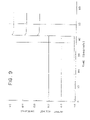
- FIG. 9 Uniformity of the response of three blood urea nitrogen (BUN) sensors, wholly microfabricated by the process of the present invention, to a change in the ammonium ion concentration of an aqueous sample from 2 to 20 mM.
- BUN blood urea nitrogen
- FIG. 10 Response of the present BUN sensor to a change in the urea concentration of an aqueous solution from 1 to 10 mM.
- FIG. 11 Response of the present BUN sensor to a whole blood sample spiked with urea.
- FIG. 12 An illustration of one possible configuration of the automated microsdispensing system of the present invention in which syringe ( 5 ), holding the material to be dispensed, is attached to a means, ( 8 ), for controlling its displacement in the direction, z, while wafer, ( 2 ), is held to a vacuum chuck, ( 1 ), whose movement in all directions is, likewise, controlled by an automated, computerized means.
- the system may also include a visual means for alignment (e.g., video camera equipped with a raticle alignable with appropriate alignment features on the wafer).
- FIG. 13 An alternative configuration of the automated microdispensing system comprising multiple syringe holders, ( 7 ).
- the syringes are inserted into openings, ( 13 ), and the vacuum chuck and wafer are positioned below the ring, ( 11 ), and through large opening, ( 12 ).
- FIG. 14 A schematic rendering of a typical sandwich assay performed using the present invention is shown.
- An immobilized ligand receptor (the first member) is positioned near the surface of the biosensor and encounters an analyte molecule (the ligand).
- the ligand binds to the receptor and is subsequently attached by an antibody-enzyme conjugate (the labeled antibody or the second member).
- a substrate is added next which undergoes a chemical transformation mediated by the enzyme (the label or substrate converter).
- the resulting intermediate product then undergoes a cascade of reactions involving the consumption of dioxygen and the production of hydrogen peroxide (both O 2 and H 2 O 2 are detectable, electroactive species) and final product (indigo when the initial substrate is an indoxyl derivative).
- FIGS. 15 a – 15 e illustrate the effect of pretreating the electrode surface to alter its surface free energy characteristics.
- the contact angle, ⁇ , of a microdispensed fluid, and eventually, the thickness of the membrane layer above the electrode, is thus controlled.
- FIGS. 16 a – 16 c show various embodiments of microdispensed biolayers including one which has a large contact angle ( FIG. 16 a ), one with a small contact angle ( FIG. 16 b ), and one which has subsequently been subjected to a photopatterning step ( FIG. 16 c ).
- the present manufacturing method is directed to the mass production of biosensors having predictable, uniform response characteristics and which biosensors are useful in a clinical setting for the convenient and real-time detection and quantitative measurement of selected analyte species.
- the integrated biochemical sensing device is formed on a transducer array by establishing discrete layered structures which are robust and possess a controlled degree of porosity, at least one of which layered structures is capable of immobilizing one or more biologically active species.
- biologically active or bioactive molecule is used to encompass ionophores, ion-exchangers, enzymes, antibodies, antigens, lectins, neurochemical receptors, oligonucleotides, polynucleotides, polypeptides, molecules of DNA, molecules of RNA, proteins, glycoproteins, metalloproteins, cofactors, immunoglobulins, and other macromolecules of physiological significance including mixtures or active fragments or subunits thereof.
- biocatalyst may also be employed especially with reference to an enzyme, enzyme-complex or mixture thereof.
- a broad class of ligand receptors may be immobilized and used in the present biosensors.
- the microfabricated sensing device, or biosensor for short is available for the analysis of most liquid samples including biological fluids such as whole-blood, lymph, plasma, serum, saliva, urine, stool, perspiration, mucus, tears, cerebrospinal fluid, nasal secretion, cervical or vaginal secretion, semen, pleural fluid, amniotic fluid, peritoneal fluid, middle ear fluid, joint fluid, gastric aspirate or the like.
- biological fluids such as whole-blood, lymph, plasma, serum, saliva, urine, stool, perspiration, mucus, tears, cerebrospinal fluid, nasal secretion, cervical or vaginal secretion, semen, pleural fluid, amniotic fluid, peritoneal fluid, middle ear fluid,
- a second and related part of the invention is a means of photodefining optional additional layers over the active layer to protect it from contact with any deleterious components of the analytical sample or solution containing the analyte (i.e., the species to be analyzed or determined).
- additional layers serve to attenuate the transport of the selected analyte into the biologically active layer, particularly when the selected analyte is present in high concentration in the sample. In so doing, the effective range of analyte concentrations in which the biosensor has a linear response is extended to higher values.
- Such analyte attenuation (AA) layers can also impair the responsiveness of the resulting sensing device and, therefore, their thickness must be carefully considered and controlled. Where the concentrations of selected analytes in the sample are not so great as to result in a nonlinear sensor response, such AA layers need not be established.
- this AA or gas permeable layer in addition to attenuating the transport of certain analytes or electroactive species, is also responsible for “insulating” the response of the sensor against the effects of sample turbulence or flow. Having a sensor response which is less sensitive to the external sample flow provides a more reproducible, reliable signal, and such a configuration is preferred particularly for the LLR-based biosensor embodiments described further herein.
- a semipermeable solid film has also been discovered, which solid film may be established and patterned (photodefined) over preselected areas of a chemical sensing device.
- This permselective layer is able to act as a barrier against the intrusion of interfering electroactive species while the desired electroactive species may freely diffuse through said film.
- the permselective layer is derived from a silanizing agent.
- a relatively stable silane precursor is dissolved or mixed in a solution which is able to hydrolyze at least two of the groups attached to the central silicon atom of the silane precursor.
- the resulting reagent solution is then established as a film across the wafer or localized over preselected areas of the wafer or base sensor.
- a semipermeable or permselective layer is then obtained under carefully controlled heating conditions.
- the permselective properties of the layer are governed, in part, by the thickness of the layer which is, in turn, dependent upon the nature and amount of silanizing agent employed as well as the method used to establish the film. Whenever desirable, mixtures of silanizing agents may be employed.
- the base transducer which frequently comprises a catalytic metal surface, may be heated in the presence of said permselective layer, to temperatures in excess of about 150° C. to about 250° C.
- This deliberate heating step provides an enhanced responsiveness of the base sensor to the primary electroactive species of interest (e.g., hydrogen peroxide or dioxygen) while maintaining the exclusionary nature of the solid film towards interfering electroactive species of higher molecular weight (e.g., uric acid or ascorbic acid).
- the transduction of the analyte concentration into a processable signal is by electrochemical means.
- These transducers may include amperometric, potentiometric, or conductimetric base sensors.
- the microfabrication techniques and materials of the instant invention may clearly be applied to other types of transducers (e.g., acoustic wave sensing devices, thermistors, gas-sensing electrodes, field-effect transistors, optical and evanescent field wave guides, and the like) fabricated in a substantially planar manner.
- potentiometric and amperometric techniques are preferred because the output signal may most easily be related directly to the response of the base sensor to a particular analyte. Specific examples directed to the production of potentiometric and amperometric type biosensors are found in the Examples Section of the present disclosure.
- this invention also relates to novel electrochemical assay procedures and to a novel wholly microfabricated LLR-based biosensor useful in determining the presence and/or concentration of selected biological (analytes) species of interest.
- This aspect of the invention relates to the discovery that a non-electroactive substrate (hereinafter the “substrate”), which does not undergo detectable electrochemical oxidation or reduction at an electrode at operating potentials which are accessible in aqueous based systems, but which undergoes a reaction with a substrate converter to form an unstable intermediate.
- the intermediate undergoes rapid auto-oxidation causing changes in the concentration of electrochemically detectable species.
- detectable species include dioxygen and hydrogen peroxide. The changes are measured and related to the concentration of the analyte of interest.
- Such novel assay procedures and LLR-based biosensor are useful in detecting the presence of, or monitoring the level of, one or more analytes in a mixture at a particular concentration, in the presence of potentially interfering substances.
- the presence or absence of a particular analyte is determined from the extent of a specific binding interaction between an analyte and the first member (a capture receptor).
- the binding interaction itself, is detected when a second member (the detection receptor), which is conjugated with a label (substrate converter), reacts with a substrate to give rise to the production and/or consumption (change in concentration) of detectable species (e.g., hydrogen peroxide or dioxygen); See FIG. 14 .
- detectable species e.g., hydrogen peroxide or dioxygen
- FIG. 14 concentration changes are electrochemically detected using the apparatus and assaying procedures of this invention.
- labeled analyte species may also be employed in “competitive assay” procedures.
- a conjugated enzyme is used as the substrate converter (label) to effect a change in the concentration of the electroactive species.
- the enzyme may be conjugated to the analyte. Any change is detected electrochemically and related to the analyte of interest.
- the invention pertains to the preferred use of the enzyme alkaline phosphatase as the label and an indoxyl phosphate derivative as the substrate.
- an esterase or hydrolase can be used to hydrolyze any indoxyl ester as long as the product undergoes rapid auto-oxidation.
- the reaction of the enzyme with the substrate itself produces such a change in the concentration of electroactive species.
- the invention is concerned with electrochemical immunoassay procedures and devices to determine analytes of interest.
- an enzyme-labeled antibody or an enzyme-labeled antigen reacts with a substrate to effect a change in the concentration of electroactive species that is susceptible to electrochemical detection.
- the enzyme-labeled antibody or enzyme-labeled antigen species is bound respectively to a complementary antigen or antibody species in a biological sample, the electrochemically detected enzyme reaction, therefore, provides for the qualitative or quantitative determination of species of interest.
- this invention pertains to the reaction of the non-electroactive indoxyl phosphoric acid ester, which is the substrate, with an alkaline-phosphatase labeled goat anti-human Immunoglobulin G (antibody) or with an alkaline-phosphatase labeled theophylline (antigen). These two reactions are associated with sandwich-type or competitive-type immunoassay methods, respectively.
- any ligand/ligand receptor pair in which at least one member can be immobilized onto the present biosensor can be incorporated into an assay procedure.
- Table II (Section 5.2.2) lists just a few examples of such ligand receptor/ligand pairs.
- substrates whose reaction with the label, or subsequent auto-oxidation, produces and/or consumes dioxygen or hydrogen peroxide may be readily contemplated.
- the invention is, therefore, not limited to the use of a phosphatase enzyme as the label, as already mentioned, because other hydrolases and labeling enzymes which are capable of reacting with a reagent to effectuate a change in the concentration of electroactive species are equally suitable (See, for example, Table II).
- the present invention therefore, provides processes and devices for performing simply and rapidly analyte-receptor assays, for example immuno- and immunometric assays, which utilize an electrochemical sensor, and which do not require lengthy incubation steps.
- the electrochemical procedure and apparatuses described herein for the detection of phosphatase (label) activity are also highly specific and relatively sensitive.
- chromogenic and turbidimetric interferences are eliminated due to the nature of the detection system.
- the use of enzyme labels in the assay together with a non-electroactive enzyme substrate also potentially facilitates the extension of known specific binding assays to greater levels of resolution than those previously accomplished, usually without the requirement of pretreatment of samples to remove interfering substances. More particularly, the assay of an analyte in the nanomolar and above concentration range is thereby achieved.
- the wholly microfabricated glucose sensor of the present invention comprises a silicon substrate on which is established thin-film structures which make up an amperometric electrochemical transducer, or base sensor.
- succeeding overlaid structures can be described as (i) a semipermeable solid film or permselective layer, superimposed over at least a portion of the base sensor, whose function is to promote the adhesion of succeeding layers over the base sensor and most importantly to prevent interfering electroactive species which are usually present in venous blood or other biological fluid samples from reaching the catalytic electroactive surface of the base sensor; (ii) a biolayer, superimposed over at least a portion of the permselective layer, in which is incorporated a sufficient amount of the bioactive molecule, in this case the enzyme glucose oxidase; and (iii) a layer responsible for attenuating the transport of the analyte species, in this case glucose, from the sample to the biolayer.
- incorporated as used herein is meant to describe any state or condition by which the material incorporated is held on the outer surface of or within a solid phase or supporting matrix.
- the material “incorporated” may, for example, be immobilized, physically entrapped, attached covalently to functional groups of the matrix, or adsorbed onto the porous surface thereof.
- any process, reagents, additives, or molecular linker agents which promote the “incorporation” of said material may be employed if these additional steps or agents are not detrimental to, but are consistent with the objectives of the present invention. This definition applies, of course, to any of the embodiments of the present invention in which a bioactive molecule is “incorporated.”
- the succeeding overlaid structures are preferably confined to the locality of the electroactive surface of the indicator electrode of the base sensor. These structures may be localized by means of micro-dispensing or photolithographic techniques.
- An additional layer which comprises a photoresist cap may optionally be present over the AA layer as a consequence of the photoforming steps. This outermost cap can be established such that it does not act as a barrier to any species of interest, if any, and, therefore, need not be removed.
- the basic chemical and electrochemical transformations on which the analytical value of the present device is premised include the convertion of glucose to gluconolactone by the action of the enzyme glucose oxidase (GOX):
- dioxygen and hydrogen peroxide are electroactive species which can undergo redox reactions on the electrocatalytic surface of the indicator electrode of the base transducer.
- Other electroactive species such as Na + , K + , Ca 2+ , NH 4 + , etc.
- the potential required for the oxidation of hydrogen peroxide is about +300 to about +600 mV, preferably +350 mV, vs. silver/silver chloride reference electrode.
- the current produced as a function of the indicator electrode potential of a glucose sensor of the present invention is illustrated in FIG. 5 for test samples comprising a HEPES buffer (X) and a 20 mM glucose solution in HEPES (Sigma Chemical Company) buffer (O).
- HEPES buffer HEPES buffer
- O Sigma Chemical Company
- This steady-state range extends from about +350 to about +600 mV as shown in FIG. 5 .
- a negative current is observed with a more negative indicator electrode potential as electrons are used up in the reduction of hydrogen peroxide to water (Eq. 3).
- a limiting steady-state negative value for the current is reached at a certain negative potential (about ⁇ 100 mV) and remains relatively constant through further increase in the negative value of the indicator electrode potential.
- One preferably operates the indicator electrode at the plateau to avoid large incremental changes in the current produced by small changes in the indicator electrode potential versus the reference electrode.
- the current generated as a result of the preceding electrochemical reactions may be related ultimately to the concentration of glucose present in the sample.
- the measured variable i.e., the current, i
- Faraday's laws in combination with Fick's Law of diffusion (Eq. 5):
- n the number of electrons involved in the fundamental electrochemical reaction at the electrode
- F Faraday's constant
- A the area of the electrode
- Dp the diffusion coefficient of the electroactive species, P.
- the rate of the enzymatic reaction in the biolayer is equal to the rate of supply of the glucose analyte through the AA layer.
- the degree of permeability (Q AS ) of the AA layer to the analyte species (AS) governs the upper limit of analyte concentration for which the sensor has a linear response, along with the activity of the enzyme, as measured by the Michaelis-Menton constant, Km.
- the steady-state current response is independent of the amount of enzyme activity in the enzyme layer. Such a condition enhances the operational stability and extends the useful shelf-life of the resulting biosensor.
- the amperometric base sensor that is a particular embodiment of the instant invention is fabricated on a substantially planar silicon substrate by means of photolithography in combination with the plasma deposition of metallic substances.
- the base sensor may comprise a unit cell containing two catalytic electrodes of identical geometry and area. This configuration allows a differential type of measurement because on only one of these catalytic electrodes is established a biolayer with active enzyme. Such a differential measurement may, in turn, enable the device to measure a current due to the activity of selected bioactive molecules over and above a background level, especially in circumstances where an interfering species may not be readily excluded by a permselective membrane.
- FIG. 1 illustrates a preferred amperometric glucose sensor unit cell which is repeated in a geometric array several hundred times on a single silicon wafer.
- Each catalytic indicator electrode, 5 iridium metal is used in this case
- the electrodes are each connected to one of three contact pads, 1 , by means of an over-passivated signal line, 2 .
- These contact pads serve as the means by which the biosensor is connected to external controlling electronics.
- the dashed area outlined by 3 represents the passivation layer.
- the permselective silane layer (functioning as an adhesion promoter and a semipermeable solid film), 6 , can be present over the entire structure or, preferably, may be localized on the electrode portions of the unit cell.
- Over the iridium catalyst are successive overlaid structures: the biolayer or enzyme layer, 7 ; the AA layer, 8 ; and the outermost layer, 9 , a photoresist cap.
- FIG. 2 illustrates the layered structures of one of the pair of indicator electrodes and the reference electrode portion of the preferred differential glucose sensor unit cell.
- the other member of the pair of indicator electrodes contains no active enzyme in the biolayer, 7 .
- the substrate wafer, 20 is silicon, in this case, with a nonconductive layer of silicon dioxide, 15 , present above it.
- Patterned titanium metal structures, 10 also serve as conducting signal lines to the contact pads of FIG. 1 .
- the iridium electrocatalyst layer is indicated by 5 in the indicator electrode structure while silver and silver chloride are designated by 4 and 4 ′, respectively, in the reference electrode structure.
- the polyimide passivation layer is 3 and the permselective silane layer (and adhesion promoter) is 6 .
- 8 is the analyte attenuation (AA) layer (also, sometimes referred to as the gas permeable membrane elsewhere in this disclosure) and 9 is the photoresist cap.
- AA analyte attenu
- the catalytic metal of the indicator electrode may be made of any of the noble late transition metals.
- other metals such as gold, platinum, silver, rhodium, iridium, ruthenium, palladium, or osmium are also suitable.
- Other elements such as carbon or mercury are also useful.
- a mixed metal oxide alloy such as iridium tantalum oxide may also be used as the metal surface.
- a dioxygen sensor is comprised preferably of a gold indicator electrode. Of these metals, silver, gold, or platinum is preferred as a reference electrode metal. A silver electrode which is subsequently chloridized is most preferred as the reference electrode.
- metals can be deposited by any means known in the art, including the plasma deposition method cited, supra, or by an electroless method which may involve the deposition of a metal onto a previously metallized region when the substrate is dipped into a solution containing a metal salt and a reducing agent.
- the electroless method proceeds as the reducing agent donates electrons to the conductive (metallized) surface with the concommitant reduction of the metal salt at the conductive surface. The result is a layer of adsorbed metal.
- the substantially planar substrate need not be a silicon wafer but can be a polished alumina wafer, glass sheet, controlled pore glass, or a planarized plastic liquid crystal polymer.
- the planar substrate may be derived from any material containing one or more of a variety of elements including, but not limited to, carbon, nitrogen, oxygen, silicon, aluminum, copper, gallium, arsenic, lanthanum, neodymium, strontium, titanium, yttrium, or combinations thereof.
- the substrate may be coated onto a solid support by a variety of methods well-known in the art including chemical vapor deposition, physical vapor deposition, or spin-coating with materials such as spin glasses, chalcogenides, graphite, silicon dioxide, organic synthetic polymers, and the like.
- Additional substrates may include gallium arsenide, lanthanum gallate, neodymium gallate, or, less desirably, strontium titanate should the establishment of superconductive materials be deemed desirable.
- good metal-substrate adhesion can be promoted by etching the substrate wafer in an argon plasma prior to plasma deposition of titanium metal.
- the titanium layer serves as the conductive material for the signal lines and also promotes the adhesion of subsequent metal layers onto the substrate surface.
- the titanium is deposited at a rate of about 2 nm/sec, to a thickness of about 20 to about 500 nm, preferably about 80 nm.
- This step is followed by plasma deposition of iridium, at a rate of about 0.5 nm/sec to a thickness of about 10 to about 100 nm, preferably to about 20 nm. It is important to exclude dioxygen during metal deposition, since even traces of dioxygen lead to the formation of iridium oxide. Excessive amounts of the oxide provide an inferior sensor surface with a substantially increased capacitance and, therefore, a slower response.
- passivation of the signal lines is an optional step.
- This omission is possible, perhaps, because of the observation that titanium, as the metal comprising the signal line, is a poor electrocatalyst for the redox conversion of the electroactive species (e.g., hydrogen peroxide, ascorbate, urate).
- a coupling reagent commonly used for this purpose is ⁇ -aminopropyltrimethoxysilane.
- the silane compound is usually mixed with a suitable solvent to form a liquid mixture.
- the liquid mixture can then be applied or established on the wafer or planar sensing device by any number of ways including, but not limited to, spin-coating, dip-coating, spray-coating, and microdispensing.
- microdispensing process can be carried out as an automated process in which microspots of material are dispensed at multiple preselected areas of the device (See, further Section 5.4, below).
- photolithographic techniques such as “lift-off” or using a photoresist cap may be used to localize and define the geometry of the resulting permselective film (See, Section 6.1.2, infra).
- Solvents suitable for use in forming the silane mixtures include aqueous as well as water-miscible organic solvents, and mixtures thereof. Alcoholic water-miscible organic solvents and aqueous mixtures thereof are particularly useful. These solvent mixtures may further comprise nonionic surfactants, such as polyethylene glycols (PEG) having a molecular weight in the range of about 200 to about 6,000. The addition of these surfactants to the liquid mixtures, at a concentration of about 0.005 to about 0.2 g/dL of the mixture, aids in planarizing the resulting thin films. Also, plasma treatment of the wafer surface prior to the application of the silane reagent can provide a modified surface which promotes a more planar established layer.
- PEG polyethylene glycols
- Water-immiscible organic solvents may also be used in preparing solutions of the silane compound.
- these organic solvents include, but are not limited to, diphenylether, benzene, toluene, methylene chloride, dichloroethane, trichloroethane, tetrachloroethane, chlorobenzene, dichlorobenzene, or mixtures thereof.
- These hydrolyzed silane reagents are also able to condense with polar groups, such as hydroxyls, which may be present on the substrate surface.
- polar groups such as hydroxyls
- the R′ group usually contains a terminal amine group useful for the covalent attachment of an enzyme to the substrate surface (a compound, such as glutaraldehyde, for example, may be used as a linking agent as described by Murakami, T. et al., Analytical Letters 1986, 19, 1973–86; and the article by Yao, T. referred to previously).
- the R′ fragment of the silane is a hydrocarbon radical comprised of 3–12 carbon atoms and R is a lower alkyl radical comprised of 1–4 carbons.
- the R′ hydrocarbon fragment may further comprise at least one heteroatom such as an oxygen, nitrogen, phosphorus, or sulfur.
- functional groups which represent stable combination of these heteroatoms such as isocyanato, cyanato, phosphate, and the like may also be present.
- organosilane reagent in which the hydrocarbon fragment R′ further comprises a suitable leaving group, preferably at the terminus of the hydrocarbon fragment.
- a silane reagent is 3-chloropropyltrimethoxysilane. In this manner, nucleophilic moieties may be covalently bound to the silane layer by displacement of the potential leaving group.
- the lower alkyl radical, R may be a methyl, ethyl, n-propyl, isopropyl, n-butyl, isobutyl, tertiary butyl group, or mixtures thereof. Routine experimentation will determine which groups are best suited to the particular manufacturing conditions being employed. Such factors as volatility, boiling point, and viscosity properties may be important considerations. The ease by which the alkoxy groups are hydrolyzed may also be dispositive. Also, because the —OR groups are substantially hydrolyzed in an aqueous environment, silane reagents in which R is also a hydrogen radical, is within the scope of the present invention.
- silane reagents can be formulated into a convenient medium, established onto a substantially planar surface, and subsequently treated under controlled conditions to provide a layer or coating with permselective properties. It should be pointed out that prior to these observations, silane reagents were employed as mere adhesion promoters, on the one hand, or to establish impermeable glasses, at the other extreme.
- freshly prepared alcoholic solutions of silicon hydroxides can be spun onto a wafer and heated to an intermediate degree such that the dehydration reaction which accompanies such heating produces a material having semipermeable properties.
- the —OR groups of the silane reagent are preferably hydrolyzed (and later dehydrated), it should be pointed out that such hydrolysis is not always necessary.
- the thermal conversion of a tetraalkoxysilane to an intermediate form of silicon dioxide can be accompanied by the evolution of an ether compound.
- the thickness and composition of the silane layer must be controlled. Such control is achieved by carefully selecting the identity of the silane reagent used, adjusting its concentration in the solvent mixture, and determining the proper rotation speed if the solution of the silane is deposited onto the wafer by spin-coating.
- silane compounds such as 3-aminopropyltriethoxysilane, N-(2-aminoethyl)-3-aminopropyltriethoxysilane, 3-aminopropyltrimethoxysilane, N-(2-aminoethyl)-3-aminopropyltrimethoxysilane, 3-isocyanatopropyltriethoxysilane, 10-aminodecyltrimethoxysilane, 11-aminoundecyltrimethoxysilane, 2-[p- ⁇ N-(2-aminoethyl)aminomethyl ⁇ phenyl]ethyltrimethoxysilane, n-propyltrimethoxysilane, phenyltrimethoxysilane, diethylphosphatoethyltriethoxysilane, or N,N-bis(2-hydroxyethyl)aminopropyltriethoxysilane, 3-
- silanes include tetrahydroxyorthosilicates (silicic acid) or tetraalkylorthosilicates such as tetramethyl, tetraethyl, tetrapropyl, tetrabutyl orthosilicates, or their mixtures.
- the preferred silane compound is N-(2-aminoethyl)-3-aminopropyl(trimethoxy)silane.
- the degree of permeability of the permselective silane membrane is due not only to the nature of the silane reagent but is also largely dependent on its thickness.
- a useful range of thickness lies in the range of about 1 to about 1000 nm, preferably between about 2 to about 20 nm.
- the preferred thickness of the silane layer particularly when the preferred silane compound is used, should be in the range of about 5 to about 10 nm.
- interfering electroactive species that one may wish to exclude from interacting with the metal catalyst surface include, but are not limited to, uric acid, ascorbic acid, salicylic acid, 2-(p-isobutylphenyl)propionic acid, cysteine, 4-acetamidophenol (acetaminophen), reduced glutathione, and the like, including their physiological salts in addition to any drug or metabolite thereof.
- the applied potential may be cycled from positive to negative values before the actual sample is introduced.
- the current signal that is measured may be small compared to the background noise. This condition may arise either from incomplete wet-up of the membrane layers or from deactivation of the electrode surface. It has been found that this signal-to-noise ratio may be increased by applying potential pulses to the electrode prior to making the measurement. Such a procedure can be conveniently carried out automatically by a suitable programmed sequence effected by the external electronics.
- the iridium electrocatalyst is poised at a potential of +350 mV versus the silver-silver chloride reference electrode with a permselective silane layer is localized over the working electrode.
- this permselective silane layer may be replaced by a gas permeable layer which preferably comprised a siloxane-nonsiloxane copolymer.
- a gas permeable layer which preferably comprised a siloxane-nonsiloxane copolymer.
- such materials can be established at a sufficient thickness and can be localized over preselected areas of the sensor, chip, or wafer.
- the support matrix in which the biologically active molecule is immobilized is preferably photoformable in addition to providing a stabilizing environment for the biocatalyst.
- a photoformable matrix behaves like a negative photoresist (although the methods are adaptable to positive resists) so that discrete structures may be applied and formed over predetermined areas of the transducer array; the biolayer is usually aligned with the iridium catalyst layer. Therefore, the support matrix material is first applied as a liquid solution in a suitable solvent, usually water, onto the wafer by spin-coating.
- the support matrix material may be about 0.02 ⁇ m to about 20 ⁇ m in thickness at this stage, preferably 0.1–2.0 ⁇ m.
- the layer may be applied in other ways including, but not limited to, dip-coating, spray-coating, or automated microdispensing.
- the radiation-sensitive material is exposed to radiant energy (e.g., visible light, ultraviolet, infrared, X-ray, electron beam, ion beam, and the like) through a patterning mask for a sufficient length of time to initiate the transformations necessary for fixing the exposed areas of the matrix to the wafer (in the case of a negative photoresist).
- radiant energy e.g., visible light, ultraviolet, infrared, X-ray, electron beam, ion beam, and the like
- the developing stage of the lithographic procedure usually involves exposing the irradiated wafer to further chemical reagents or solvents which ultimately results in the removal of unexposed matrix material while exposed areas remain fixed to the wafer.
- hydrated proteinaceous substances which contain a sufficient amount of a photosensitizer (photoactivator or photoinitiator) are able to behave as suitable negative photoresist materials but in which a wide range of bioactive molecules may be immobilized or incorporated. It has also been found that these water-based photoformable multicomponent negative resist materials may also comprise various other components (sometimes nonproteinaceous) which modify the characteristics and properties of the resulting resist.
- the proteinaceous substance of the resist mixture acts as a crosslinkable matrix, and the photoactivator serves to nitiate the crosslinking reaction upon exposure to radiant energy.
- a proteinaceous substance is meant to encompass substances which are generally derived from proteins whether the actual substance is a native protein, an inactivated protein, a denatured protein, a hydrolyzed species, or a derivatized product thereof.
- suitable proteinaceous materials include, but are not limited to, albumin, casein, gamma-globulin, collagen and collagen derived products (e.g., fish gelatin, fish glue, animal gelatin, and animal glue). It is important to note that the photoformable proteinaceous mixtures of the present invention are comprised substantially of the protein-derived material.
- proteinaceous material itself, which serves as the immobilization matrix brought about by the photoinitiated crosslinking reaction.
- This matrix is uniquely suited to act as a photodefinable membrane which also provides a very hospitable environment for the bioactive molecule.
- the preferred substance is fish gelatin derived from the skin of Northern cold water fish, also known as “Teleostean Gelatin” (Sigma Chemical Co., St. Louis, Mo.).
- the multicomponent photoformable resist material may contain 0.01–50 g/dL fish gelatin solids, preferrably 0.5–10 g/dL.
- a wide range of high oxidation state transition metal compounds can serve as a suitable photosensitizer.
- Representative compounds include, but are not limited to, ferric chloride, ferric ammonium citrate, ferric potassium citrate, ferric ammonium oxalate, ferric sodium oxalate, ferric potassium oxalate, ferric oxalate, ferric ammonium tartrate, manganese tartrate, potassium dichromate, and ammonium dichromate.
- the most preferred materials are ferric ammonium citrate and ammonium dichromate which may be present in the material at about 0.1–10 g/dL, preferrably about 1–2 g/dL.
- the photoactivator can itself be a multi-component system comprising a photosensitizing dye and a transition metal compound, preferably of high oxidation state.
- the photosensitizing dye may be a xanthine-based dye, such as fluoroscein (or a halogenated derivative thereof), eiosin, rhodamine, or methylene blue, and the like.
- the metallic component may include, but is not limited to, salts of Pb 2+ , Hg 2+ , Ti 4+ , Cu 2+ , CrO 4 ⁇ , Ag + , and MoO 4 ⁇ in which the appropriate counterion is preferably selected to confer solubility to the metal salt.
- the appropriate counterion is preferably selected to confer solubility to the metal salt.
- radiant energy such as UV light
- suitable electron donors such as citrate ion
- hydroxyl radicals are produced (Eq. 8) which, in turn, promote the crosslinking of the proteinaceous material, especially in the presence of added crosslinking agents, such as a polyunsaturated compound.
- the chromium system works slightly differently in effectuating a change in the solubility of the protein material.
- exposure of the dichromate initiates the transformation shown in Eq. 9.
- the chromate ion may then combine with functional groups of the gelatin to alter its solubility characteristics.
- the developing medium for the chromium system may be composed solely of water.
- Additional compounds may be added to the resist material to modify its characteristics and properties.
- Crosslinkers such as N,N′-methylenebisacrylamide can be used to promote patternability.
- Other additives are listed in Table I.
- the preferred additive is N,N′-methylenebisacrylamide which may be at a concentration range of about 0.01 to about 10 g/dL, preferably about 1–2 g/dL. It is understood that the examples listed in Table I are not exhaustive and are not meant to limit the scope of the present invention.
- many other types of crosslinking agents maybe employed so long as two functional groups are present in the compound.
- the preferred functional group is a vinyl group.
- Polyhydroxylated compounds such as glycerol, and alcohol sugars, such as sorbitol, erythritol, and mannitol, ° may be added to the crosslinked matrix to promote the formation of a more open (porous) structure.
- porosity-altering substances may also include simple salts and may be used in combination with the polyhydroxylated compounds.
- Detergents may be added also to promote planarization of the matrix during spin-coating onto the wafer.
- Nonionic surfactant materials such as polyethylene glycol, Triton X-100, or reduced Triton X-100 may be used at a concentration of about 0.01 to about 1 g/dL, preferrably at about 0.1 g/dL.
- the biologically active component can either be pre-mixed with the negative photoresist (e.g., fish gelatin/ferric ammonium citrate) and co-deposited therewith or may be impregnated thereafter into the patterned support matrices.
- the negative photoresist e.g., fish gelatin/ferric ammonium citrate
- spin-coating a negative resist is preferred since spinning offers the best dimensional control over the thickness of the layer. It may also be less wasteful, of course, if the biologically active component is impregnated into the already patterned structure.
- microdispensing enough material to cover an area about three times the diameter of the catalytic electrode will dry to leave a substantially planar region directly above the catalytic electrode. Additional details of the automated microdispensing system are given in Section 5.4 and in FIGS. 12 and 13 .
- reagents comprising adenosine diphosphate (ADP) and glycerol may be microdispensed in the vicinity of an ATP sensor, which reagents may be dissolved by an added fluid during the operation of the sensor.
- ADP adenosine diphosphate
- glycerol may be microdispensed in the vicinity of an ATP sensor, which reagents may be dissolved by an added fluid during the operation of the sensor.
- the wafer can either be partially diced (the dicing saw is used to score the wafer surface so that it can easily be broken along the score line after processing) or completely diced.
- wafer dicing using a commercial dicing saw such as those supplied by Microautomations Inc., Santa Clara, Calif. or Kulicke and Soffa Industries Inc., Willow Grove, Pa. is performed with the wafer stuck on a flat plastic sheet in the center of a metal frame.
- the thickness of this layer after patterning is controlled largely by the solids content of the resist, its viscosity, the surface energy of the substrate wafer, and the subsequent development time.
- the surface can actually be tailored to spread the microdispensed material in a controlled manner. For instance, if the surface surrounding the indicator electrode is either polyimide or silicon dioxide, it can be made hydrophilic by exposure to an oxygen, water, argon, or nitrogen plasma. (A fluorocarbon plasma treatment makes silicon dioxide hydrophilic but a polyimide hydrophobic) (See, Section 5.4.1.3, below).
- oxido-reductases with an organic cofactor, e.g., the flavoproteins: glucose oxidase, sarcosine oxidase, cholesterol oxidase, NADH oxidase, and glycerol-3-phosphate oxidase; oxidoreductases with a metal ion at the active site, e.g., uricase; hydrolases, e.g., creatininase; and kinases, e.g., glycerol kinase and hexokinase.
- organic cofactor e.g., the flavoproteins: glucose oxidase, sarcosine oxidase, cholesterol oxidase, NADH oxidase, and glycerol-3-phosphate oxidase
- oxidoreductases with a metal ion at the active site e.g., uricase
- hydrolases
- enzymes which may be immobilized within the proteinaceous matrix include, but are not limited to, urease, creatinine amidohydrolase, creatinase, creatine kinase, cholesterol esterase, glucose dehydrogenase, lactate dehydrogenase, alkaline phosphatase, alanine transaminase, aspartate transaminase, amylase, lipase, esterase, ⁇ -glutamyl transpeptidase, L-glutamate oxidase, pyruvate oxidase, diaphorase, bilirubin oxidase, or appropriate mixtures of these and the above-mentioned enzymes.
- Additional macromolecules of biological significance such as proteins, lectins, neurochemical receptors, molecules of deoxyribonucleic acid (DNA), molecules of ribonucleic acid (RNA), polypeptides, glycoproteins, metalloproteins, immunoglobulins, cofactors, antibodies, antigens, receptors, ionophores, ion-exchangers, oligonucleotides, polynucleotides and mixtures, active fragments or subunits thereof, may also be immobilized by means of the negative photoresist process described herein.
- the above-mentioned substances must not be sensitive to brief exposure to ultraviolet light, dichromate ion, ferric ion, ferrous ion, crosslinking agents, or hydrogen peroxide (with certain photosensitizing agents), however, if they are to be present before the photoforming and subsequent development steps. Those that are denatured or inactivated under these conditions may be introduced subsequent to the patterning step as an aqueous solution, for example, as mentioned previously and further, infra.
- the thickness and porosity of the preferred proteinaceous layer is important in controlling the final properties of the sensor. If the layer is too thick, the response will be impaired, and if it is insufficiently porous, the amount of enzyme which can be loaded into the structure will be too low.
- the proteinaceous layer may range in thickness from about 10 nm to about 0.5 mm, preferably about 0.05 to about 5 ⁇ m.
- bioactive molecule e.g., enzyme
- Sensors manufactured with defects in the thickness or porosity of the proteinaceous layer will unavoidably have a limited shelf-life or useful lifetime, and will have impaired performance characteristics. It is therefore a crucial object of the present invention to provide a microfabrication process which is reliable and establishes overlaid biolayers in a reproducible and controllable manner.
- the thickness of the layer can be controlled, among other things, by the content of solids in the negative photoresist, the spin speed, and the development time.
- the porosity of the crosslinked layer can be controlled, for example, by adding certain reagents to the negative photoresist which are radical scavengers (free-radical inhibitors) and can thus impede the degree of crosslinking.
- One such reagent is sorbitol.
- Other porosity-altering substances may include monosaccharides, disaccharides, oligosaccharides, polysaccharides, sugar alcohols, simple salts, or combinations thereof.
- the photoformable gelatin layer is formulated to contain from about 0.01 to about 4 g/dL of sorbitol. It has been found that too much sorbitol, for example over 5 g/dL, results in a composition which undergoes very little crosslinking and is, therefore, not photoformable.
- porous characteristics of the immobilizing layer also aid in the initial “wet-up” stage of the operable biosensor. This stage involves the “wetting” and calibration of the biosensor which is stored essentially dry under a controlled humidity environment. Any structural features which speed up this process shortens the waiting time needed before the results are obtained.
- analyte species of interest may include, although this list is by no means exhaustive, dissolved and total amounts of carbon dioxide, carbon monoxide, ammonia, dioxygen, ethanol, ionized calcium, sodium ion, potassium ion, lithium ion, hydrogen ion, chloride ion, magnesium ion, ammonium ion, hydrogen peroxide, ascorbic acid, glucose, cholesterol, uric acid, esterified cholesterol, urea, creatinine, creatine, triglycerides, lactate dehydrogenase, creatine kinase, alkaline phosphatase, creatine kinase-MB, alanine transaminase, aspartate transaminase, bilirubin, amylase
- biolayers of the present invention have utility in a wide range of applications in which a biologically active molecule is to be incorporated in the solid phase at preselected areas of a given device.
- biolayers may be spin-coated across a surface, painted, screen-printed, dipped, or dispensed as microspots, they may be localized at strategic, precise areas by, for example, photolithography.
- these materials can be applied to any surface comprising part of a diagnostic system or kit, for example.
- the components of the test can be separated in different sections of the test surface and only later combined during the actual performance of the test.
- Such binary, ternary, or higher multicomponent systems can incorporate a chromogenic reagent which may then produce a characteristic color.
- the film-forming latices may also be coated onto reactor beads, hollow fibers, or the inside walls of a bioreactor to promote the chemical transformation of reactive substrates.
- more than one number or one type of biolayer may be established to accomplish a series of transormations leading to the overall detection of a complex analyte like adenosine triphosphate, for example, or more than one analyte (e.g., cholesterol and glucose).
- film-forming latices may be microdispensed, for instance, over proteinaceous layers.
- the reverse sequence, proteinaceous layers over microdispensed film-forming latices may also be accomplished.
- a plurality of proteinaceous layers may also be established readily.
- the sensor can function as a glucose sensor per se; that is, glucose solutions placed in contact with this device will produce a signal output (i.e., current) which is proportional to the concentration of glucose in the sample.
- a signal output i.e., current
- two limitations must still be overcome.
- a sensor would have a response proportional (i.e., linear response) to the concentration of glucose in a sample over only a very narrow range of glucose concentration. Typically, this range spans about 0.1 to about 2.0 mM in glucose, hardly appropriate for the range of glucose concentrations (1–25 mM) encountered in fluid samples obtained from diabetic subjects, for instance.
- the proteins, cells, and other components of whole blood, or any other biological fluid would quickly foul such a sensor and prevent the uniform transport of analyte molecules.
- the blood sample may first be centrifuged or filtered to remove its heavier constituents, one would ideally, and most conveniently, wish to perform the tests on whole blood.
- glucose oxidase becomes saturated kinetically at a glucose concentration as low as 4 mM.
- the sensor provides no analytical information at higher analyte concentrations (i.e., the response becomes nonlinear, even zero order).
- a possible solution to this problem of low saturation levels would involve providing some means for allowing only a certain, but constant, fraction of the glucose, or any other desired analyte, to reach the enzyme-containing layer without significantly attenuating the transport of the co-reactant dioxygen (Eq. 1). In other words, such a layer would tend to attenuate the amount of analyte reaching the biolayer but would also serve as a gas permeable membrane.
- an additional layer of material termed the analyte attenuation (AA) layer
- AA an additional layer of material
- the thickness of the AA layer governs to a large degree the amount of analyte that reaches the active enzyme. Its application must, therefore, be carried out under strict processing conditions, and its dimensional thickness must be closely controlled. In other words, the AA layer must be established in a manner which is consistent with one of the primary objects of the instant invention.
- An AA layer which is too thin fails to provide a sufficiently linearized signal, while an overly thick layer is expected to reduce the current excessively and also slow down the response time of the sensor. In utilizing an AA layer, the problem of sensor fouling by extraneous materials is also obviated.
- AA material As in the microfabrication of the underlying layers, an important factor which affects close dimensional control over the AA layer is the composition of the AA material itself.
- copolymers for example, a copolymer of a siloxane and a nonsiloxane moiety, are particularly useful. These materials can be microdispensed or spin-coated to a controlled thickness. Their final architecture may also be designed by patterning and photolithographic techniques in conformity with the other discrete structures described herein.
- nonsiloxane-siloxane copolymers examples include, but are not limited to, dimethylsiloxane-alkene oxide, tetramethyldisiloxane-divinylbenzene, tetramethyldisiloxane-ethylene, dimethylsiloxane-silphenylene, dimethylsiloxane-silphenylene oxide, dimethylsiloxane- ⁇ -methylstyrene, dimethylsiloxane-bisphenol A carbonate copolymers, or suitable combinations thereof.
- the percent by weight of the nonsiloxane component of the copolymer can be preselected to any useful value but typically this proportion lies in the range of about 40–80 wt %.
- the dimethylsiloxane-bisphenol A carbonate copolymer which comprises 50–55 wt % of the nonsiloxane component is preferred.
- These materials may be purchased from Petrarch Systems, Bristol, Pa. (USA) and are described in this company's products catalog.
- AA layers include, but are not limited to, polyurethanes, cellulose acetate, cellulose nitrate, silicone rubber, or combinations of these materials including the siloxane nonsiloxane copolymer, where compatible.
- a solution of dimethylsiloxane-bisphenol A carbonate block copolymer in a mixture of chlorinated and aromatic solvents is spin-coated onto the wafer.
- Ethereal and carbonyl-containing solvents may also be used advantageously in the solvent mixtures.
- the thickness of this layer is controlled by the non-volatile content of the mixture and the spin-speed; its porosity to glucose is controlled also by the solvent composition.
- suitable solvents include, but are not necessarily limited to, diphenylether, benzene, toluene, xylenes, methylene chloride, trichloroethane, tetrachloroethane, chlorobenzene, dichlorobenzene, phenetole, 2-methoxyethylether, acetophenone, propiophenone, and cyclohexanone.
- the AA layer thickness may be in the range of about 2 nm to about 10 ⁇ m, but is preferably between about 5 nm to about 10 nm for most applications.
- the thinner layers are most useful for the attenuation of low-molecular weight molecules (e.g., those having a molecular weight of about 100 to about 300). If the layer is sufficiently thick and cast from the appropriate solvent system, it can act as a gas permeable layer in which only gaseous molecules like ammonia, dioxygen, or hydrogen peroxide can permeate. It should be understood that the nature of the polymer film, along with its thickness, governs the dimensional threshold at which the analyte attenuation layer becomes a gas permeable layer.
- a given layer may function as a gas permeable layer at a lesser or greater thickness relative to another.
- Such routine experimentation to determine the useful range of thickness, for a given function of a given material is deemed within the capability of a person skilled in the art.
- certain layers with a thickness of about 5–1000 nm can function as an AA layer, whereas some layers having a thickness of about 100–5000 nm would function as a gas permeable membrane.
- some overlap in the thickness ranges is to be expected.
- AA layer An important aspect of the establishment of the AA layer is the successful patterning of the polymer layer without deleteriously affecting the function and performance of the underlying layers, particularly the activity of the enzyme should a biolayer be present underneath. It is desirable to localize the area covered by the AA material and to remove it from regions of the wafer where it would interfere with other functional aspects of the sensor.
- the contact pads, 1 ( FIG. 1 ), for example, must be unhindered in their ability to make electrical contact with a microprocessor unit.
- a gelatin-based negative photoresist similar to that employed for the enzyme-containing layer and known as NPR 6, is spin-coated over the polymer layer and patterned to leave a photoresist cap only in locations where the AA copolymer is required.
- This negative photoresist is available commercially from Norland Products Inc., New Brunswick, N.J. Excess AA copolymer can then be removed by exposure to a basic etchant which may be comprised of an alcoholic solution of potassium hydroxide or tetramethyl ammonium hydroxide. It has been discovered that the resist cap does not affect the response of the glucose sensor and, therefore, its subsequent removal is optional.
- aqueous-based photoresists known to those skilled in the art could also be used to pattern the AA layer.
- the response of the glucose biosensor as disclosed herein is linear over a much wider range of glucose concentration due to the presence of the AA layer. Without the AA layer, the sensor would have been less appropriate for use in undiluted biological materials.
- the final step in manufacturing the device involves dicing the wafer to yield individual glucose sensors.
- This step may be conveniently performed by an automated machine with a diamond-impregnated rotating saw-blade and which is equipped with a means for delivering water jets to cool the blade and to remove swarf and the like.
- This relatively drastic step is capable of effectively destroying all but the most robust thin-film structures which are present on the substrate wafer.
- this step can, in fact, be successfully performed on the embodiments of the glucose sensor as described herein without a deleterious effect on the selectivity, sensitivity, and overall performance of the sensor.
- the disclosures of the present invention represent, therefore, a true microfabrication manufacturing process which can be utilized in the production of identical microcomponents useful as sensors for analyte molecules of physiological, biological, and medical significance.
- the wafers may be scribe” the wafers with the automated rotary saw prior to establishing the structures which comprise the bioactive layers of the chemical sensor.
- This process involves a partial dicing step which outlines each individual sensor on the wafer.
- the scribing process facilitates a final cleaving step at the end of the manufacturing process but still leaves the scribed wafer with sufficient structural integrity to endure the intervening process steps.
- the scribing process is described in more detail in the Examples section of this disclosure.
- adenosine-5′-triphophate (ATP) sensor which involves the co-immobilization of more than one enzyme is also given.
- This process is achieved by microdispensing a mixture comprised of glycerol kinase and glycerol-3-phosphate oxidase.
- catalysts e.g., enzymes
- reagents e.g., adenosine diphosphate, ADP
- the base sensor is comprised of a gold indicator electrode superimposed over the primary titanium layer as shown in FIG. 7 .
- the metallic components of the dioxygen base sensor are as illustrated in the figure and resemble closely the hydrogen peroxide sensor depicted in FIG. 2 except that the preferred electrocatalyst metal 5 is gold in this case.
- the gas permeable layer 8 ′ effectively envelopes the entire underlying electrolyte layer in the configuration of FIG. 7B , and, thus, more effectively seals off the electrode region from the external fluid.
- the preferred materials for use in the electrolyte layer and photoresist cap are the photoformable proteinaceous mixtures described herein.
- the gas permeable membrane/AA layer is preferably formed using the siloxane/nonsiloxane copolymers described previously.
- FIG. 7A can be established using a single photoexposure step in which the photoinitiated crosslinking reaction can take place both in the underlying electrolyte layer and the overlaid photoresist cap.
- the structure of the dioxygen sensor of FIG. 7B would require a first exposure to radiant energy followed by the developing step to form the underlying electrolyte layer.
- the AA material would then be established followed by the photoresist cap.
- the final structures are then localized over the preselected areas by a second exposure through a photolithographic mask, then developed in the appropriate developing solution.
- the conditions of irradiation can be adjusted such that all of the sensitive layers receive an appropriate exposure to provide photocrosslinked matrices.
- This penetrating irradiation step is only possible, however, where the intervening layers (in this case, the gas permeable layer) do not significantly absorb the radiant energy.
- preferred materials for use in the AA layer should not be strongly absorbing in, say, the ultraviolet region of the electromagnetic spectrum.
- Such preferred materials are the siloxane/nonsiloxane copolymers, for example.
- the gas permeable layer can be established at a thickness such that only small gaseous molecules, like dioxygen, can effectively reach the electrode portions of the sensor. Therefore, interfering electroactive species may be substantially excluded from the electrocatalyst surface in this manner.
- the gas permeable layer thus performs the same permselective function as the permselective silane layer and can be used for that purpose, in the alternative.
- the electrolyte layer surrounding the electrode structures in cooperation with the other overlaid structures, provides a “stagnant” environment, in terms of external turbulence, within which the redox reactions can take place on the metal surfaces.
- the amount of redox species reaching the electrode surface is governed by the presence of the gas permeable and electrolyte structures such that the electrode response is independent of the flow or turbulence characteristics of the external fluid sample.
- the electrolyte layer which is hydrated under normal operating conditions, is able to provide protons for the redox reaction of dioxygen.
- the resulting multi-layered device is much more reliable and able to provide more accurate and repoducible measurements relative to a bare metal electrode configuration.
- FIG. 8A the biolayer, 7 , is superimposed over the underlying gas permeable layer of a dioxygen sensor as in FIG. 7 .
- the AA layer 8 and photoresist cap 9 are established over the biolayer as described previously. If the bioactive molecule present in the biolayer is glucose oxidase, then the resulting device is able to function as a glucose sensor, with the gas permeable layer performing a similar function as the permselective silane film described earlier.
- FIG. 8B illustrates a device which is described further in Section 5.2, but which takes advantage of the underlying electrolyte and gas permeable layers ( 12 and 8 ′, respectively) against external fluid turbulence or sample flow.
- a coupling means, 40 is used to covalently attach a ligand receptor or immunreactive species, 45 , to the outermost surface of the layered structures (e.g., to the top of the photoresist cap, 9 ).
- such a device is useful as a ligand/ligand receptor-based (LLR) biosensor which expands considerably the range and scope of possible analyte species which may be detected or analyzed by the wholly microfabricated biosensor devices of the present invention, without being unduly sensitive to the movement of the external fluid samples.
- LLR ligand/ligand receptor-based
- FIG. 5 shows the steady-state current for glucose as a function of the operating potential of the glucose sensor with respect to the on-board silver/silver chloride reference/counter electrode for a solution containing HEPES buffer 50 mM (pH 7.4) containing 100 mM NaCl (O) and the same solution containing 20 mM glucose (X).
- HEPES buffer 50 mM pH 7.4
- the current is associated with hydrogen peroxide oxidation at the iridium electrode surface derived from the enzymatic oxidation of glucose by the enzyme glucose oxidase.
- potentials between ⁇ 200 to ⁇ 100 mV the current is derived from the reduction of hydrogen peroxide at the iridium electrode surface.
- the observation of a plateau current for both the oxidation and reduction of hydrogen peroxide suggests that the biosensor current is limited by transport of glucose through the AA layer into the enzyme layer, as discussed earlier.
- FIG. 6 shows a calibration curve for the glucose biosensor in which the steady-state current measured at +350 mV is plotted as a function of glucose concentration.
- the response is linear in the range 1–30 mM glucose. Additional experiments demonstrate that the current response is not significantly effected by: (i) changes in pH over the range commonly encountered in biological fluids e.g., pH 6.8–8.2; (ii) changes in the partial pressure of dioxygen over the range 20–200 mm Hg; or (iii) changes in chloride ion concentration over the range 50–200 mM.
- the glucose biosensors indeed, any of the biosensor embodiments of the instant invention may be used in conjunction with the devices which are the subject of co-pending U.S. application Ser. Nos. 245,102 and 187,665 (the complete disclosures of which are incorporated by reference herein) to perform measurements of glucose or other analyte levels in biological fluids such as human plasma, serum, or whole blood.
- the microfabricated biosensors may be adapted for performing analyses based upon intermolecular affinity and/or immunochemical complex interactions. Such interactions are manifest in numerous complementary ligand/ligand receptor complexes such as antigen/antibody, antibody/anti-antibody, biotin/avidin, immunoglobulin G/protein A, enzyme/enzyme receptor, hormone/hormone receptor, substrate/enzyme, DNA (or RNA)/complementary polynucleotide sequence, drug/drug receptor, and the like.
- an assay may be devised in which one or the other member of the complex may be the analyte species of interest, and the other component may be used as the sensor-immobilized ligand receptor or immunoreactive species.
- a first member e.g., the ligand receptor
- immobilized e.g., by covalent attachment or adsorption
- the ligand or analyte species is allowed to bind to the first member, forming an affinity, immuno, complementary, or like complex.
- a second member with a suitable label is then introduced and binds to the analyte.
- a substrate for the enzyme label is introduced which is converted by a process initiated by the label.
- electroactive species such as dioxygen or hydrogen peroxide
- electroactive species such as dioxygen or hydrogen peroxide
- the second member and the substrate may be collectively referred to as reagents with which the sample suspected of containing the analyte species may be treated or combined.
- Such reagents may further comprise other components which may enhance the interaction of the reagent or reagents with the analyte species or to amplify the change in the concentration of detectable species so produced.
- the first member may be immobilized by covalent attachment to a functionalized silane layer, with or without the benefit of a crosslinking agent (e.g., glutaraldehyde, epichlorohydrin, and others).
- a crosslinking agent e.g., glutaraldehyde, epichlorohydrin, and others.
- the immunoreactive species or ligand receptor is covalently bound to the outermost layer of a sensor having a structure of the type illustrated in FIG. 7 or 8 .
- the base sensor may be predisposed to hydrogen peroxide (e.g., iridium) or dioxygen (e.g., gold).
- the exact assay procedure used is a choice which can be made by one skilled in the art and can be a procedure based, for example, on existing “sandwich” assays, competitive assays, or the like.
- the base sensor is an electrochemical sensing device
- the instant embodiment is particularly useful in the qualitative and quantitative measurement of analytes which are of interest in immunology or substance detection.
- an LLR-based biosensor that uses procedures based on existing sandwich assays
- a particular analyte species such as a particular antigen
- the presence of a particular analyte species, such as a particular antigen may be detected, for example, by immobilizing an antibody (first member), capable of binding to the specific antigen of interest, onto the base sensor of the present invention.
- the resulting LIR sensor is then brought into contact with a mixture comprising the sample, in which the presence of the antigen is to be determined, and a second antigen-specific antibody (second member) which is labeled suitably.
- the antigen (first member) may be immobilized on the base sensor, and the antigen-specific antibody may be the analyte species.
- a second member, comprising an anti-antibody, may then be present to bind to the analyte species.
- This second member would also be “labeled” with an enzyme, such as alkaline phosphatase. An enzyme substrate is then introduced.
- the antibody or antigen may be attached non-covalently (e.g., by adsorption) or attached covalently, directly or through an intermediate crosslinking reagent, to functional groups present on the silane layer.
- a photoresist cap may also be present which photoresist cap is preferably comprised of a proteinaceous substance.
- the proteinaceous substance also possesses a multitude of reactive functional groups, notably amino and carboxylate groups, to which the first member of the assay may be bound covalently.
- the base sensor may be selected from an amperometric electrochemical device to which the applied potential allows the electrochemical conversion of hydrogen peroxide or dioxygen.
- antibody is immobilized via any coupling means well-known in the art to the outermost layer of the preferred dioxygen sensor, which outermost layer comprises a proteinaceous substance or mixture thereof, and aligned over the indicator electrode, to provide a structure such as that illustrated in FIG. 8B .
- a hydrogen peroxide base sensor with an overlaid permselective silane layer (also acting as an adhesion promoter) is manufactured as already described in the preceding sections.
- the permselective silane layer is useful as a screen against interfering species which may otherwise come into contact with the base sensor and which may interfere with the analysis during incubation of the appropriate reactive components, including the test sample.
- the silane layer is confined to preselected areas of the base sensor.
- the substrate wafer bearing the silanized base sensors, or other electrolyte/gas permeable layers is preferably “scribed” (as described in Section 5.1.5) before the layer of immunoreactive species is established.
- the scribed wafer can then be exposed to a solution of glutaraldehyde, or any other suitable crosslinking reagent known to the skilled practitioner, and subsequently to a solution of the desired first member.
- the resulting wafer may then be cleaved to provide individual chips or devices.
- substrate as used generally in the art and in this disclosure can refer to one of two substances. Where the base sensor is the subject of the discussion, “substrate” refers to the substantially planar surface or wafer which forms the foundation of the transducer. When the context of the disclosure is focused on an enzymatic process, “substrate” refers to the chemical species which is transformed by that enzymatic process.)
- the electrochemical assay procedures of the invention relate to many analytes of interest. Such assay procedures involve sandwich and competitive assay procedures using this invention's novel biosensor, which is an electrode described in detail infra, to detect changes in the concentration of electroactive species.
- a solution is prepared which possibly contains the analyte of interest and a second member (detection receptor), which is labeled with a substrate converting moiety. If the analyte of interest is present, then the second member and the analyte form a complex.
- the sandwich assay also uses an LLR-based biosensor on which is immobilized a first member (capture receptor of the analyte). The complex obtained from the analyte and second member is brought into contact with the biosensor to form a capture receptor/analyte/detection receptor complex on the biosensor.
- the biosensor is washed to remove other components of the solution which are not complexed to the biosensor.
- the biosensor to which the complex is bound is then placed in contact with a non-electroactive substrate whereby the label of the second receptor reacts with the substrate.
- This reaction ultimately (i.e., directly or indirectly) initiates a sequence of steps which effectuate changes in the concentration of electroactive species (i.e., produces hydrogen peroxide and/or consumes dioxygen) which are electrochemically measured.
- the measurement provides for the determination of the corresponding analyte concentration in the sample.
- enzyme linked immunosorbent assay (ELISA) competitive assays are performed.
- a capture receptor is bound to the biosensor, and the biosensor is placed in contact with a sample containing the analyte of interest that competes with a fixed quantity of analyte labeled with a substrate converter.
- a sample containing the analyte of interest on the surface of cellular material can also be used as the analytical sample.
- the biosensor is washed to remove uncomplexed components of the solution.
- the biosensor is contacted with the non-electroactive substrate whereby the substrate reacts with the label to induce changes in the concentration of electroactive species.
- an electrode is poised at an optimum preselected potential sufficient to induce the reduction or oxidation of the electroactive species produced and/or consumed by the enzymatic reaction.
- the change in the concentration of the electroactive species is measured and correlated to the analyte which one is seeking to detect.
- the assay pertains to an electrochemical sandwich immunoassay or a competitive immunoassay.
- a sandwich assay pertains to the use of an immunosensor on which an antigen (receptor) is immobilized.
- a sample possibly containing mono- or polyclonal antibodies of interest (analyte) is admixed with an enzyme-labeled antigen or enzyme-labeled anti-antibody, and formed antibody/(enzyme-labeled antigen or enzyme-labeled anti-antibody) complexes in the admixture are contacted with the immunosensor to form an immobilized antigen/antibody/(enzyme-labeled antigen or enzyme-labeled anti-antibody) complex on the immunosensor.
- the immunosensor is then preferably washed to remove admixture components other than the immobilized complex.
- the immunosensor is then put in contact with the non-electroactive substrate whereby the enzyme moiety of the immobilized complex reacts with the substrate, which reaction ultimately (i.e., directly or indirectly) initiates a sequence of steps which effectuate changes in the concentration of electroactive species (i.e., produces hydrogen peroxide and/or consumes dioxygen) which are electrochemically measured.
- the measurement consequently, provides for the determination of the antibody concentration in the sample.
- the assay is particularly suited to allergy specific assays where the first member or capture receptor is an allergen (antigen) bound to the adhesion layer (or in other embodiments, a photoresist layer), and the second member or detection receptor is an antibody to IgE.
- the IgG response to allergens may be measured similarly, i.e., by using an antibody against IgG, as the second member.
- a mono- or polyclonal antibody (capture receptor) is immobilized on an electrode to form the immunosensor.
- a sample possibly containing the antigen of interest is admixed with an enzyme-labeled antibody (detection receptor), and formed antigen/enzyme-labeled antibody complexes in the admixture are contacted with the immunosensor to form immobilized antibody/antigen/enzyme-labeled antibody complexes on the immunosensor.
- This immunosensor is then processed as is noted regarding the prior described sandwich immunoassay to determine the antigen concentration in the sample.
- FIG. 14 schematically illustrates certain aspects of a particular embodiment of the instant invention.
- a competitive assay pertains to the contacting of an immunosensor, to which is bound an antigen to antibodies (mono- or polyclonal), with a sample possibly containing the antibodies of interest and a fixed quantity of enzyme-labeled antibodies.
- the immunosensor is washed to remove uncomplexed components of the solution and then the immunosensor is contacted with the non-electroactive substrate whereby the substrate reacts with the label to induce changes in the concentration of electroactive species.
- an electrode is poised at an optimum preselected potential sufficient to induce the reduction or oxidation of the electroactive species produced and/or consumed by the enzymatic reaction.
- the change in the concentration of the electroactive species is measured and correlated to the analyte which one is seeking to detect.
- An alternative embodiment of the competitive assay pertains to the contacting of an immunosensor, to which is bound antibodies to an antigen, with a sample possible containing an antigen of interest and a fixed quantity of enzyme-labeled antigen.
- the sample to be analyzed and the labeled ligand receptor are typically premixed before being brought into contact with the LLR-based biosensor.
- Such an initial premixing or incubation step is not necessary, however, because all the necessary binding interactions may be allowed to take place on the LLR sensor.
- a ternary or “sandwich” complex comprised of an immobilized antibody/antigen/labeled antibody is formed.
- unbound materials are then preferably removed from the sensor. This step may be carried out by using a wash solution which may also contain a non-ionic detergent.
- This wash solution is displaced, in turn, by a solution containing a substrate which is complementary to the enzyme label.
- unbound materials may be removed concurrently with the introduction of the enzyme substrate (i.e., the solution containing the enzyme substrate may also function as the wash solution).
- the ensuing enzymatic reaction leads to the production and/or consumption of electroactive species, which species may undergo a redox reaction at the indicator electrode.
- the analysis is completed by measuring the signal output (current) produced in response to the electrochemical reaction.
- the magnitude of the output current is proportional to the changes in the amount of electroactive species present at the indicator electrode at the steady-state and which amount is proportional, in turn, to the original concentration of the analyte of interest.
- an enzyme-linked immunosorbent assay ELISA
- ELISA enzyme-linked immunosorbent assay
- Table II lists a few enzyme/substrate pairs which may be utilized in the method or one equivalent to that disclosed herein for the electrochemical detection of selected immunoreactive analyte or particular ligand species.
- alkaline phosphatase acting on a suitable phosphoric acid ester, is preferred principally because of its high turnover rate.
- Other enzymes may also be preferred according to the requirements of a particular system. Those workers of ordinary skill can readily determine the particular combination of characteristics (e.g., stability, specificity, etc.) best suited to a given set of conditions.
- immunoreactive species to be immobilized onto the base sensor depends on the particular analyte species to be measured and is within the skill of those knowledgeable in the art.
- a first member capture receptor; e.g., an antibody
- a second antibody having a binding site on the antigen different from that of the first receptor, is labeled with a suitable enzyme.
- the sample to be analyzed for the presence of Immunoglobulin G (antigen) is then incubated with the receptor conjugate (enzyme-labeled antibody) and then brought into contact with the LLR sensor as described above.
- an antigenic substance may also be immobilized, instead, onto the biosensor where a particular antibody is the analyte species of interest.
- the sequence of steps may be varied also, and other modifications can be incorporated into the assay procedure as warranted by the particular analysis to be performed.
- the assay can be performed by preparing a mixture comprising the test sample, the labeled antibody, and the substrate. This mixture is brought into contact with the LLR-based biosensor on which is immobilized a first antibody member specific to the antigen of interest. A quantitative measure of the amount of analyte species is made by comparing the signal output of the sensor with one nearby in which the immobilized antibody (first member) is absent or unreactive towards the antigen. The difference between the two signal outputs can be related to the concentration of the antigen in the test sample.
- analytes include, but are not limited to, IgG, IgM, prostatic acid phosphatase, prostate specific antigen, alphafetoprotein, carcinoembryonic antigen, leutenizing hormone, choriogonadotrophin, creatine kinase MB, and the like.
- liquid samples containing material having analytes associated therewith such as antigens associated with bacteria, parasites, fungi, or viruses including for example, Neisseria gonorrhea, Gardnerelle vaginalis, Trichomonas vaginalis, Candida albicans, Chlamydia trachomatis , hepatitis B, herpes, rubella, acquired immunodeficiency virus (HIV or HTLV III), cytomegalovirus and autoimmune antibodies can be detected using a membrane that will trap the cells or a membrane to which a receptor specific for the antigen is bound.
- antigens associated with bacteria, parasites, fungi, or viruses including for example, Neisseria gonorrhea, Gardnerelle vaginalis, Trichomonas vaginalis, Candida albicans, Chlamydia trachomatis , hepatitis B, herpes, rubella, acquired immunodeficiency virus (HIV or HTLV III), cyto
- sandwich assay procedures are also contemplated using a biosensor that selectively immobilizes a first member.
- a first member and a second member are added to a sample containing the analyte of interest.
- This admixture can form a first member/analyte/second member complex that selectively binds via portions of the first member of the complex to the biosensor.
- the three component admixture can be contacted with the biosensor, whereby the first member is selectively immobilized on the biosensor followed by the sequential complexing to the first member (capture receptor of the analyte) and then second member, or an analyte/second member adduct can complex with the immobilized first member.
- the biosensor can be sequentially contacted with the first sensor analyte containing sample and detection receptor to yield the first member/analyte/second member complex bound to the biosensors.
- the resulting sensor-bound complexes are then treated with a substrate as previously disclosed to assay for the analyte.
- any type of affinity binding interaction between two molecular species may be exploited so long as one of the pair may be immobilized onto the electrochemical device (preferably, via functional groups present on the outermost layer, which may be the silane layer or a proteinaceous substance) and the other may be labeled suitably.
- the assay of the invention can also be used to detect an enzyme by binding the enzyme's receptor to the biosensor.
- a labeled antibody against the enzyme can be used to detect formation of a receptor/enzyme/labeled antibody complex on the biosensor.
- Monoclonal antibodies may also be used in any of the assays described herein.
- the assay of the invention can also be used to detect nucleic acid oligomers.
- the biosensor is functionalized with (has bound on it) a nucleic acid oligomer as a probe-receptor for nucleic acid material in a sample.
- the probe may be an oligomer of DNA, for example, complementary to a sequence in the nucleic acid of interest and can be used to bind a polynucleotide, RNA, or DNA as the analyte.
- Detection of the analyte-receptor complex can be done using a second nucleic acid oligomer complementary to a non-interfering region of the nucleic acid analyte of interest, the second oligomer being labeled to permit detection.
- an antibody which recognizes the hybrid formed by the polynucleotide sequence and the probe may also be used as the immobilized ligand receptor. Still other ligand receptors may be useful such as DNA-binding proteins and the like.
- receptors for certain drugs may be isolated and immobilized, and so forth.
- the sample may then be incubated with the LLR-based biosensor, and the amount of bound enzyme may be determined by the addition of a suitable substrate which gives rise to the production or the consumption of an electroactive species upon interaction with the enzyme.
- the procedures may also be varied to use a label other than an enzyme. The use of the label must allow the production of an electroactive species or the consumption of an electroactive species (i.e., gas, or some other electroactive species) which are electrochemically measured.
- Table III is provided herewith as a working guide. It must be stressed, however, that appropriate combinations of analyte, immobilized receptor, and the specific method used are virtually unlimited. In addition, other types of outer surfaces or solid phases may prove useful for the immobilization of ligand receptors or immunoreactive species.
- BCIP 5-bromo-4-chloro-3-indoxyl phosphate
- BCIP BCIP, or a suitable analog thereof
- an agent in connection with an electrochemical assay procedure, for effectuating changes in the concentration of electroactive species.
- the assay procedure and/or the devices used to perform the analyses are chosen from the methods and sensors disclosed herein.
- the present method employing BCIP, or a suitable analog thereof is not so limited particularly because macroelectrodes, indeed, any amperometric device, may be used to perform the electrochemical measurements.
- a receptor or analyte labeled with an enzyme converts the added indoxyl phosphate substrate (BCIP) to a hydrolyzed species that forms unstable intermediates.
- the subsequent auto-oxidation reaction produces indigo with the concommitant consumption of dioxygen and production of hydrogen peroxide.
- the corresponding change in the concentration of O 2 or H 2 O 2 can then be determined electrochemically at a preselected potential as previously discussed in Section 5.1, supra.
- the electrochemical detection of the electroactive species may be performed using any amperometric electrochemical device, and such measurement would not be hampered by any turbidity or other condition which may interfere with existing calorimetric or spectrophotometric measurements.
- a phosphatase enzyme including the acid phosphatase, on BCIP, or any suitable analog or derivative thereof (e.g., other substituted indoxyl phosphates) capable of ultimately yielding (or consuming) electroactive species, is utilized in conjunction with the microfabricated biosensors of the instant invention to provide an assay procedure with totally unexpected and unanticipated efficiency, sensitivity, and clinical applicability.
- the potentiometric chemical sensor for urea can be viewed as a system which is constructed from functionally dissimilar components, as is the glucose sensor (supra).
- the outermost layer the one in contact with the analyte solution, permits the transport of urea while also serving to immobilize the enzyme urease.
- This enzyme catalyzes the hydrolysis of urea to ammonia and carbon dioxide, as follows:
- the ammonia thus produced from Eq. 10 exists predominantly as ammonium ions.
- the ammonium ion concentration at the electrode interface can be measured. In this type of measurement, the potential difference between the indicator electrode and a reference electrode is recorded.
- the analytical value of the measurement is derived from the fact that the magnitude of the potential difference is related by the Nicolsky equation (Eq. 11, below) to the concentration of the analyte, in this case, urea:
- E E o + RT nF ⁇ log ⁇ [ A + ⁇ a _ , b _ ⁇ k a _ , b _ ⁇ ⁇ B ] ( 11 )
- E the measured electromotive force (signal)
- R the gas law constant
- T the absolute temperature
- F is the Faraday constant
- A is the activity of the analyte species a
- B is the activity of an interfering chemical species b
- k a,b is the interference coefficient associated with the effect of the presence of chemical species b on the electrochemical potentiometric determination of the activity of the analyte species a
- E o is a constant independent of T, A, or B.
- the unit cell for the BUN sensor comprises a thin film silver-silver chloride indicator electrode operating in combination with a thin-film silver-silver chloride reference electrode.
- the substrate wafer, 20 is silicon, with an overlaid insulating layer of silicon dioxide, 15 .
- the first metal layer, 10 is titanium and serves the same function in the BUN sensor as in the glucose sensor.
- Succeeding layers 4 and 4 ′ are the silver and silver chloride layers.
- the remaining layers of the indicator electrode include (i) a semipermeable membrane film, 25 , comprising an organic polymer layer (e.g., poly(vinyl chloride)—PVC) and an ammonium ion ionophore; and (ii) the outermost biolayer, 11 , comprising in this particular sensor, a film-forming latex (e.g., poly(vinyl acetate-co-vinyl alcohol)) and a sufficient amount of the enzyme urease.
- a semipermeable membrane film, 25 comprising an organic polymer layer (e.g., poly(vinyl chloride)—PVC) and an ammonium ion ionophore
- the outermost biolayer, 11 comprising in this particular sensor, a film-forming latex (e.g., poly(vinyl acetate-co-vinyl alcohol)) and a sufficient amount of the enzyme urease.
- the reference electrode portion of the unit cell may be comprised of overlaid structures as shown in FIG. 3 .
- the metal and chloridized layers of the reference electrode are covered by an electrolyte layer, 12 , which may comprise any material which is able to hold a high concentration of salt but which is, preferably, photoformable.
- an electrolyte layer, 12 which may comprise any material which is able to hold a high concentration of salt but which is, preferably, photoformable.
- a fish gelatin formulation is the preferred material and may first be photopatterned and subsequently saturated with a salt, such as potassium chloride.
- a separate gas permeable membrane, 8 ′ may also be present which serves to diminish the loss of electrolyte or salt to the bulk analytical sample but allows the rapid wet-up (i.e., passage of H 2 O or other small gaseous molecules) of the reference electrode prior to commencing the sample analysis.
- the photoresist cap, 9 which may be a remnant of the patterning process need not be removed if it does not bar the free passage of solvent, solute, or ions.
- the reference electrode structure described in co-pending U.S. application Ser. No. 07/156,262, filed Feb. 16, 1988, the disclosures of which are incorporated herein by reference is used.
- a reference electrode structure in which the distance between the liquid junction and the surface of the silver/silver chloride is sufficiently large, such that the concentration of electrolyte in the immediate vicinity of the Ag/AgCl structure is substantially constant for a period of time sufficient to perform a measurement of the potential difference between the indicator electrode and the reference electrode.
- a thick film ammonium ion-sensitive structure comprising a poly(vinyl chloride) (PVC) binder, tris(2-ethylhexyl)phosphate as a plasticizer, and nonactin as the ionophore.
- the indicator electrode can be made selective for different ions by using the same binder and plasticizer composition but with different ionophores. For example, valinomycin, monensin and (methyl)monensin, or tridodecylammonium chloride have been used to make potassium, sodium, or chloride-ion selective electrodes, respectively.
- ionophores may include, but are not limited to crown ethers, trialkylamines, or phosphate esters, and the like.
- other polymeric binder materials may be used besides PVC. These polymers may include, for example, silicon rubber, polytetrafluoroethylene plastics, or derivatives of PVC containing ionizable functional groups (e.g., carboxylates).
- plasticizers suitable for use in the present invention may include, but are not limited to tris(2-ethylhexyl)phosphate, nitrocymene, 2-nitrophenyloctyl ether, dibutyl sebacate, diethyl adipate, phthalates, propylene carbonate, 5-phenylpentanol, or mixtures thereof. Still other binders and ionophore combinations may occur to those skilled in the art which are within the scope of the present invention.
- the resulting semipermeable ion-selective film may have a thickness in the range of about 2 ⁇ m to about 200 ⁇ m, preferably about 10 to about 30 ⁇ m.
- indicator electrode, 30 , and the adjacent reference electrode, 35 are each connected by an overpassivated signal line, 2 , to a contact pad, 1 .
- the unit cell is confined within a rectangular area, which is repeated in a square array several hundred times on a single silicon wafer.
- other indicator electrodes may be present in the biosensor for the simultaneous measurement of ionic species (e.g., Na + , K + , or Cl ⁇ ) in addition to ammonium ion.
- a particle latex comprises a solid polymeric structure, such as polystyrene, which is coated with a hydrophilic material that allows the polymer particle to be waterborn.
- Particle latex materials have been used traditionally to immobilize all manner of biologically active materials (See, Kraemer, D. et al., U.S. Pat. No. 4,710,825).
- an important property of particle latices which is unsuitable in the present application is that even after these materials have been dried, the particles can be redispersed easily in water.
- a film-forming latex is a colloidal solution comprised of a mobile polymeric liquid core, such as a vinyl acetate, with a hydrophilic outer coating.
- a film-forming latex is made by an emulsion-polymerization process in which a water-immiscible organic monomer or a mixture of monomers is added to an aqueous medium containing a free radical catalyst. The polymerization may be initiated, for example, by mechanical agitation (See, for example, Vanderhoff, J. W., J. Poly. Sci. Polymer Symposium 1985, 72, 161–198). When this material is dried the particles coalesce to form a film which cannot be redispersed in water. Because film-forming latices are water-based and contain both hydrophilic and hydrophobic components, one may speculate that these compositions are able to provide a stabilizing environment for biologically active species and constitute an effective medium for the immobilization or incorporation of same.
- film-forming latices from both natural and synthetic sources are of significant utility.
- the following synthetic monomers, their chemically-modified analogues, copolymers, or mixtures thereof may be used to make a film-forming latex: vinyl acetate, ethylene, acrylate or acrylic acid, styrene, or butadiene.
- These and many other materials known to those skilled in the art are available commercially from many sources including Reichhold, Air Products, DuPont, Dow Chemical, or Imperial Chemical Company. Natural isoprene-based polymers are also useful and available from Imperial Adhesives and Chemicals, Inc. and from General Latex and Chemical Corp.
- non-latex water-soluble components e.g., proteins, enzymes, polysaccharides such as agarose, or synthetic polymers such as poly(vinyl alcohol), poly(vinyl pyrrolidone), and the like
- non-latex water-soluble components e.g., proteins, enzymes, polysaccharides such as agarose, or synthetic polymers such as poly(vinyl alcohol), poly(vinyl pyrrolidone), and the like
- non-latex water-soluble components e.g., proteins, enzymes, polysaccharides such as agarose, or synthetic polymers such as poly(vinyl alcohol), poly(vinyl pyrrolidone), and the like
- the established film adheres effectively to a planar substrate even in the presence of large amounts of additives (i.e., enzymes).
- a layer on a planar substrate can be defined using a thick layer (about 5 to about 200 ⁇ m) or a viscous film-forming latex composition ( ⁇ 500 Centipoise as measured on a Brookefield RV viscometer) if a thick layer (about 5 to about 200 ⁇ m) is required. However, if a thin layer (about 0.2 to less than about 5 ⁇ m) is required, a composition with a lower viscosity is used which can be microdispensed directly onto the indicator electrode, or alternatively, either microdispensed or spin-coated onto a positive resist layer (e.g., Shipley AZ 1370 SF) which has been patterned to leave the area over the indicator electrode exposed.
- a positive resist layer e.g., Shipley AZ 1370 SF
- Any suitable solvent known in the art such as n-butylacetate and the like, is then used to lift off the resist, along with the excess latex.
- a separate technique using a photoresist cap may also be used. Specific examples of the “lift-off” and resist cap techniques are given in the Examples Section, infra.
- control of the surface energy may be used beneficially to control the spreading of the microdispensed reagent (and, thus, its dimenionality, such as thickness).
- a fluorocarbon (e.g., cF 4 ) plasma treatment of a polyimide layer surrounding the indicator electrode causes the aqueous based latex to exhibit a high contact angle (i.e., minimizes spreading and maximizing thickness).
- crosslinking agents are well-known in the art and may include such compounds as glyoxal, glutaraldehyde, melamine formaldehyde, urea formaldehyde, and phenol formaldehyde.
- Suitable crosslinking agents may possess at least two functional groups which may include vinyl, carboxyl, anhydride, amine, amide, epoxy, hydroxyl, cyano, isocyanato, thio, halo, in addition to formyl, and stable combinations of these functional groups (e.g., a chloroalkylepoxide).
- These additives can significantly enhance the wet-strength of the biolayer and extend the shelf-life of the completed biosensor.
- one or more of the biologically active macromolecules listed in the preceding or following sections of this disclosure may be successfully immobilized using a film-forming latex such as Elvace or Elmer's Glue.
- a more responsive sensor may result when using a film-forming latex compared with the photoformable proteinaceous matrix used in the glucose sensor.
- a film-forming latex is used to immobilize the enzyme urease.
- a higher enzymatic activity is achieved in this case compared to a urea sensor in which the biolayer is manufactured from a photoformable fish gelatin.
- the porosity of the biolayer can be controlled to a significant extent by incorporating certain additives, such as salts (e.g., sodium chloride) or sugar alcohols (e.g., mannitol, erythritol, or sorbitol), into the latex mixture prior to deposition.
- certain additives such as salts (e.g., sodium chloride) or sugar alcohols (e.g., mannitol, erythritol, or sorbitol)
- sugar alcohols e.g., mannitol, erythritol, or sorbitol
- FIG. 9 shows the response of the ammonium ion sensor as a function of time measured against the on-chip reference electrode.
- the measurements are done on a sensor starting in the dry state.
- the initial slow increase is due to wetting of the sensor by the solution.
- the sensor responds very quickly so that measurements can be done within a few seconds.
- the test solution changes concentration from 2 to 20 mM ammonium.
- the three graphs on the figure are from different urea sensors and show the uniformity of the response.
- FIG. 10 The response of the BUN sensor to aqueous urea solutions is given in FIG. 10 .
- the initial decrease and subsequent increase is due to the wetting of the sensor. After about 40 seconds the concentration is changed from 1 to 10 mM urea.
- the slower response in comparison to the sensor of FIG. 3 , is due to the outer film-forming latex layer through which mass transport is necessary and where also the catalytic reaction occurs before the ions can reach the underying indicator electrode.
- the Nicolsky selectivity coefficient are taken into account in determining the urea concentration.
- FIG. 11 shows the response of a BUN sensor to whole blood which has been spiked with urea to elevate the level. The response is similar to the previous one.
- the BUN sensor has a linear range between 1 and 20 mM urea and a measurable range up to 40 mM in blood.
- microdispensing system which is based on a wafer prober (Pacific Western Systems, SP1-C), is comprised of a vacuum chuck and a syringe, each of which are attached to separate means for altering the vertical, horizontal, lateral, or rotational displacement of these key elements of the system.
- SP1-C Pacific Western Systems
- the movements of both elements may be controlled via a single personal computer using customized software (Turbo-C) to drive the machinery.
- the position of the vacuum chuck may be reproducible within ⁇ 13 microns or better in either x or y directions.
- the drop sizes which can be dispensed reproducibly extends over a wide range. For volume sizes between about 5 to about 500 nanoliters (nL), the drops can be applied with a precision of about 5%. A solenoid having a 0.1% precision rating is sufficient for this purpose.
- the height of the tip of the syringe needle above the biosensor should be between about 0.1 to about 1 mm, depending on the volume to be dispensed: generally, the smaller the volume of the drop, the lower the elevation of the needle from the sensor (Please refer to Section 5.4.1.1, below).
- the precise alignment of the syringe needle with the preselected area of the biosensor can be achieved optically, if necessary, by means of a camera and a reticle. Such an operation can be performed manually by an operator or automatically by means of a visual recognition system incorporating aspects of artificial intelligence. Of course, the rate at which material can be dispensed onto the devices is limited by the speed with which the elements of the system can arrive at their specified positions. However, multiple syringe configurations may be operated advantageously as described further below.
- a suitable microdispensing system will have the elements of a vacuum chuck, 1 , on which the wafer, 2 , is held and the syringe, 5 , holding the material to be microdispensed.
- the liquid material is applied through a needle, 6 , with the aid of pressurized nitrogen or other suitable gas supplied at 10 .
- the flow of the pressurized gas is controlled by a solenoid valve, 9 , which provides precise pulses of gas to dispense predetermined volumes of material.
- the support arm, 7 may be connected to a means 8 for adjusting the vertical position, Z, of the syringe and needle.
- the film-forming latex materials containing the appropriate bioactive molecule may be dispensed on the biosensor chip, 3 , at a preselected region, 4 .
- the vacuum chuck is also coupled to a means for varying the displacement of the wafer multidirectionally. It is understood, of course, that the means, 8 , may also be varied multidirectionally, if desired.
- FIG. 13 An alternative embodiment of the instant microdispensing device is illustrated in FIG. 13 , which comprises a plurality of independently controllable microdispensing syringe assemblies. These assemblies are preferably mounted on a circular support, 11 , having an opening, 12 , below which opening the wafer and vacuum chuck may be positioned appropriately.
- the dimension of a microdispensed layer (especially its thickness) are governed by a variety of factors. More specifically, the inventors have found that these factors involve, among other things, the volume of and the manner in which a fluid is dispensed, the composition and surface tension of the fluid, and the free energy characteristics of the surface onto which the fluid is dispensed.
- the following sections seek to explore more fully the intricate interplay between these multiple factors and how their individual and collective effects can be harnessed to provide a more reproducible but versatile manufacturing process.
- the drop will grow in size until the gravitational force acting on the mass of the drop exceeds the opposing forces maintaining contact with the needle tip.
- These opposing forces include the adhesive forces between the needle tip and the fluid or liquid, and surface tension of the liquid itself. It is well established that at low liquid flow rates where discrete drop formation is complete, the drop volume is fixed. However, the volume may be changed by varying any of the fluid related parameters discussed above, or by changing the diameter of the needle tip thus changing the available surface area for fluid adhesion.
- the present inventors have also demonstrated that the exterior surface of the needle may be coated with an additional layer of a material that modifies the fluid adhesion.
- a hydrophopic polytetrafluoroethylene (PTFE) coating applied to the needle tip reduces the natural drop size of an aqueous based latex material by reducing the adhesive forces between the drop and the needle tip.
- the needle tip can be coated with a hydrophilic material (e.g., crosslinked poly(vinyl alcohol) (PVA) to enlarge the volume of the emerging drop before gravity pulls it away from the needle tip.
- PVA crosslinked poly(vinyl alcohol)
- the surface tension, a between a pure liquid and its vapor phase can be changed by adding reagents.
- reagents For example, if a fatty acid is added to water the hydrophilic portion of the molecule is cohesive, whereas the hydrophobic portion is not, i.e., it resides in a high energy solvated state. Minimal work is required to bring the solvated portion of the molecule to the surface, and thus, the surface layer becomes enriched in the non-cohesive portion of the fatty acid, reducing the surface tension.
- solutes such as ionic salts added to aqueous systems increase cohesion (ion-dipole interactions) between water molecules in the bulk of the fluid, increasing the work required to introduce them to the surface. The surface tension of the fluid is thus increased.
- the contact angle is high and when adhesive forces dominate the contact angle is low (See, for example, FIG. 15 ).
- a hydrophilic liquid will have a low contact angle on a hydrophilic surface, whereas a hydrophobic liquid will have a high contact angle. If the contact angle, ⁇ is greater than 90° the surface is said to be nonwetting. Simple optical instrumentation is available for measuring contact angles.
- microdispensable fluid compositions of the present invention are prepared to have a controlled optimized surface tension. Suitable additives are used when necessary.
- the hydrophobicity or hydrophilicity of the fluid is controlled in the same manner. Where a cured membrane is required as the end product, the solids content and volatile solvents content are carefully adjusted. Moreover, the ratio of these components is also used to control the viscosity.
- compositions for application onto a given surface are described further in the Example Section.
- examples for formulations are provided for establishing layers which are sensitive to Cl ⁇ , Na + , K + , pH, NH 4 + , and Ca ++ ions.
- These compositions comprise PVC polymer, plasticizers, ionophores and solvents with viscosities generally higher than those used for planar casting (e.g., spin-coating) of membranes. It has been found that these higher viscosity compositions cure or dry without deformation of the membrane layer.
- the solvent system is selected to provide the appropriate surface tension and stability.
- the solids content (wt %) of plasticizer, PVC polymer, and ionophore are preferably 60–80%, 15–40% and 0.5–3%, respectively.
- the Cl ⁇ sensor ratios of 25–40% plasticizer, 25–45% PVC, and 25–35% ionophore are preferred.
- the present inventors have discovered that tailoring the surface free energy of the substrate, or surface onto which the fluid is dispensed, provides an unexpected degree of control over the final dimensions, especially the thickness, of the resulting layer. Even more surprising, it has been discovered that a process which combines these techniques gives predictable and reproducible results. Furthermore, the resulting process is highly versatile, allowing the deposition of arrays of biolayers of varied composition and utility.
- a control fluid e.g., a mixture of 80% glycerol and 20% water
- a contact angle of 50° is attained.
- Pretreating the surface with a tetrafluoromethane plasma renders the polyimide surface more hydrophobic. If the same control fluid is now dispensed over the CF 4 -treated surface, contact angles of 50° to 120° are attained.
- the polyimide surface is first treated with an oxygen plasma, the surface is made more hydrophilic and contact angles of 10° to 50° are attained with the same control fluid.
- FIG. 15 a is a representation of the perimeter of a silver/silver chloride electrode circumscribed by a polyimide layer.
- FIG. 15 b is the corresponding elevational view of the electrode.
- the contact angle ⁇ is small for a microdispensed hydrophilic fluid resting on a polyimide surface which had been exposed to an O 2 plasma.
- the contact angle is larger if the surface is untreated and increases further if the surface is first treated with a CF 4 plasma.
- the configuration of the dispensed fluid over a given surface is manageable to a large extent by a careful choice of the conditions to which the given surface is (or is not) subjected.
- the effective contact angle of the control material is determined by the composition of the gas and the power, duration, and pressure of the plasma.
- the silicon wafers with microfabricated base sensors and polyimide passivation layers may be plasma treated under any of the above listed conditions.
- the argon plasma has the effect of etching the surface (hydrophilic), whereas the CF 4 plasma makes the surface more hydrophobic.
- a tailored surface energy affords control over the spreading of the material of a microdispensed fluid or membrane material. Control over the spreading affords control over the membrane thickness. Control over the membrane thickness leads, in turn, to highly reproducible membrane response characteristics.
- the surface is preferably tailored so that the contact angle which the microdispensed fluid makes with the surface is large. For example, before an aqueous latex membrane is microdispensed, the surface is first plasma treated to yield a contact angle for water (control fluid) in the range 50°–70°. This point is illustrated in FIG. 16 a for a potentiometric ammonium ion sensor.
- the surface is tailored to have a low contact angle for the dispensed fluid (e.g., for a 1 ⁇ m NPR enzyme layer microdispensed as an aqueous solution, the contact angle may be 10–30° (See, FIG. 16 b ).
- the surface energy of the perimeter of an electrode surface is tailored in such a fashion to create conditions under which one obtains the desired membrane thickness upon dispensing of a given volume of a photoformable proteinaceous mixture.
- the dispensed fluid flows in a controlled manner and produces a film of a controlled thickness.
- subsequent exposure of the resulting film to active radiation, at preselected areas of the photoresist film renders those exposed areas insoluble to a developing medium.
- a patterned layer is obtained after the development step. The dimensions of the resulting layer are controlled, therefore, in a manner and degree not unlike that obtained through spin-coating.
- a multiple syringe assembly such as that illustrated in FIG. 13 , may be employed to dispense several types of biolayers. All the resulting layers may then be localized further to preselected areas of the electrode by exposure to a single photopatterning step.
- a creatinine sensor and a creatine sensor are also described in the Examples section of the disclosure.
- creatinine amidohydrolase and sarcosine oxidase are immobilized in a photoformed gelatin layer.
- the creatinase is then immobilized in a film-forming latex applied as an overlaid structure.
- the creatine sensor is constructed in a similar manner, with the creatinine amidohydrolase being omitted from the gelatin layer.
- the sensors described herein are designed to be compatible with a disposable sensing device.
- a disposable sensing device for use in real time fluid analysis (See, co-pending U.S. application Ser. No. 07/245,102, the entire disclosures of which is incorporated herein by reference).
- These sensors must therefore have the capability of retaining an excess amount of enzyme to ensure an extended shelf-life when stored dry.
- the layers must be thin enough and permeable enough, however, such that wet-up, calibration, and a measurement of an analyte in a biological fluid can all be performed in real time, preferably within a total of about one minute.
- the preferred design for a glucose sensor is a unit cell which comprises two identical iridium catalytic electrodes both surrounded by a single silver-silver chloride combined reference and counter electrode (See, FIGS. 1 and 2 ). Each of the three electrodes is connected by an over-passivated signal line to one of three contact pads.
- the unit cell is confined within a rectangular area which is repeated in a square array several hundred times on a single substrate, in this case, a silicon wafer.
- the exposed silver is removed by using a 0.9 M aqueous solution of ferric nitrate as the etchant.
- N-methylpyrrolidone solvent is used to remove the remaining photoresist, thus exposing the required silver structure.
- the underlying titanium layer is then processed to leave material in regions which act as either a contact pad or a signal line. This process is achieved by repeating the same lithographic process, as described above for silver, with the exception that a 3.9 M aqueous mixture of nitric acid also containing 0.78 M of hydrofluoric acid is used as the etchant.
- a photo-definable polyimide (DuPont 2703) is spin-coated onto the wafer.
- the wafer has been exposed to UV light and developed with a solvent mixture of butyrolactone and xylene (6:4 v/v), the polymer is heated and “imidized” in an oven at about 350° C. for about 30 minutes under an inert atmosphere and left to cool to about 150° C. before removal.
- iridium catalytic electrode To fabricate the iridium catalytic electrode, positive photoresist (Shipley, AZ 1370 SF) is patterned as described above. A layer of iridium (0.1 ⁇ m) is then sputtered onto the wafer. Excess photoresist and excess metal on the resist are then removed by treatment with N-methylpyrrolidone to leave an octagonal (width 200 ⁇ m) iridium layer. The areas of silver are then chloridized by dipping the entire wafer into a 12 mM aqueous solution of potassium dichromate also containing 60 mM hydrochloric acid.
- An alcoholic solution of the silane compound, N-(2-aminoethyl)-3-aminopropyltrimethoxysilane is prepared as follows: 10 g of a mixture comprising the silane (2 mL), water (9 mL), and ethanol (90 mL) is mixed with 50 g of ethanol. A sufficient amount of this alcoholic silane solution is spin-coated onto a wafer. The wafer is then baked in an oven at about 90–250° C. for about 5–30 minutes.
- the silane layer can be established on preselected areas (i.e., over the catalytic electrode surface) of the silicon wafer having the base sensor in place.
- a layer of positive photoresist (Shipley, AZ 1370 SF) is spin-coated across the wafer and soft-baked at about 90° C. for 30 minutes. It is then patterned as described previously to leave the area over the catalytic electrode exposed.
- a 0.5 g/dL solution of N-(2-aminoethyl)-3-aminopropyltrimethoxysilane in deionized water is then spin-coated onto the wafer and baked at about 90° C. for 15 minutes under an inert atmosphere.
- the silane layer may also be established locally by means of a photoresist cap.
- a typical procedure is outlined below:
- a silicon wafer with a patterned array of amperometric electrochemical sensors in which the catalytic working electrode is a thin-film of iridium metal and the reference electrode is silver-silver chloride, is spin-coated with a 0.5 g/dL solution of N-(2-aminoethyl)-3-aminopropyl trimethoxysilane in deionized water.
- the wafer is then heated to about 160° C. for about 15 minutes.
- the wafer is then spin-coated with positive photoresist (Shipley, AZ 1370 SF), soft-baked at about 100° C. for about 60 seconds, and then patterned by means of exposure to ultraviolet light through a mask.
- the resist is then developed (Shipley, AZ 351) to leave a resist cap over the catalytic iridium working electrode.
- the wafer is then etched in a 1/500 fold dilution of hydrofluoric acid (10 M) in deionized water to remove excess polymerized N-(2-aminoethyl)-3-aminopropyltrimethoxysilane.
- Other protic solvents such as lower alkanols, may be used as the solvent for the hydrofluoric acid. Mixtures of protic solvents may also be used.
- concentration of hydrofluoric acid in the protic solvent lies in the range of about 0.001 to about 0.01 weight percent.
- the resist cap is then removed by exposure of the wafer to n-butylacetate followed by ultrasonication for 15 minutes. The above procedure leaves the silane layer only on the catalytic electrodes.
- the wet etch step involving hydrofluoric acid is replaced by a dry etch using an oxygen plasma, achieving similar results.
- Photoformable fish gelatin containing ferric ammonium citrate as photoinitiator may be purchased from Norland Products, Inc., New Brunswick, N.J. These negative photoresists (the commercial materials are referred to as NPR followed by an integer) may also be prepared fresh by mixing aqueous solutions of fish gelatin (cold water fish skin sold as a 45% aqueous solution by Sigma Chemical Company, Cat. No. G 7765), metal complex, and a crosslinking agent.
- a sugar alcohol such as sorbitol or mannitol, may also be included in the formulation to alter the porosity of the photoformed matrix.
- sorbitol or mannitol may also be included in the formulation to alter the porosity of the photoformed matrix.
- NPR 6 which contains a chromium-based photoinitiator, may also be used.
- the enzyme biocatalyst, glucose oxidase may be mixed into the NPR or freshly prepared fish gel mixture and spin-coated across the base sensor wafer.
- a typical formulation may comprise about 2 to about 35 g/dL fish gelatin, about 2 to about 100 mM metal complex, about 2 to about 100 mM crosslinking agent, and about 1 to about 25 mg/mL enzyme.
- the formulation may also contain about 0.1 to about 10 g/dL sugar alcohol and about 0.001 to about 1 g/dL of a detergent.
- a preferred formulation comprises 10% fish gelatin, 13.3 mM ferric citrate, 13.3 mM N,N′-methylenebisacrylamide, and 6.7 mg/mL glucose oxidase.
- Another suitable formulation comprises NPR-29 (diluted with deionized water to a final protein content of 10% by weight of the total mixture), glucose oxidase (6.7 mg/mL), sorbitol (2 g/dL), and Triton X-100 (0.03 g/dL).
- the pH of the fish gelatin or NPR formulations may be adjusted with added carbonate or sodium hydroxide, if desired, to a pH above about 4 before addition of the enzyme. Most preferably, the pH of the formulation should be greater than about 4 but less than about 9 to prevent a significant inactivation of the biocatalyst.
- the amount of proteinaceous material applied on the wafer can be varied to adjust the thickness of the final biolayer. Preferably, this thickness is about 0.1 ⁇ m. More economically, the formulations may be microdispensed directly over the indicator electrodes of the base sensors. The wafers are then exposed to UV light (6 mW/cm 2 , 30 seconds) through an appropriate mask and developed in 1 g/dL aqueous hydrogen peroxide for about 20 seconds.
- the protein matrix may be established and patterned on the wafer without the enzyme present.
- the entire wafer may then be immersed in an aqueous solution of the enzyme glucose oxidase (Sigma type VII: 150 IU/mg) at a concentration of 20 mg/mL for 2 minutes. This procedure is effective to impregnate the gelatin layer with a sufficient amount of enzyme. Excess enzyme can be removed by washing the wafer with water.
- glucose oxidase Sigma type VII: 150 IU/mg
- An alternative design for a glucose sensor is a unit cell which comprises two identical iridium catalytic electrodes both surrounded by a single silver-silver chloride combined reference and counter electrode (See, FIGS. 1 and 2 ). Each of the three electrodes is connected by an unpassivated signal line to one of three contact pads.
- Elimination of the passivation step reduces the number of manufacturing steps.
- the absence of the passivation layer also reduces the gross topography on the wafer and allows better control of the thickness of materials which are subsequently spin-coated across the wafer.
- the unit cell is confined within a rectangular area which is repeated in a square array several hundred times on a single substrate, in this case, a silicon wafer.
- Layers of titanium (0.1 ⁇ m) and silver (0.5 ⁇ m) are sputtered consecutively onto the wafer surface.
- the silver is then processed to localize it to a region which in the final device acts as the combined reference and counter electrode and the contact pads.
- This step is achieved by a standard lithographic technique in which the wafer is spin-coated with positive resist (Shipley, AZ 1370 SF). After UV exposure of the photoresist through a mask and development (Shipley, AZ 351), the exposed silver is removed by using a 0.9 M aqueous solution of ferric nitrate as the etchant. N-methylpyrrolidone solvent is used to remove the remaining photoresist, thus exposing the required silver structure.
- iridium catalytic electrode To fabricate the iridium catalytic electrode, positive photoresist (Shipley, AZ 1370 SF) is patterned as described above on the wafer and then a layer of iridium (0.1 ⁇ m) is sputtered onto the wafer. Excess photoresist is then removed by treatment with N-methylpyrrolidone to leave an octagonal (width 200 ⁇ m) iridium layer. The underlying titanium layer is then processed to leave material in regions which act as either a contact pad or a signal line. this process is achieved by repeating the same lithographic process, as described above for silver, with the exception that a 0.78 M aqueous solution of hydrofluoric acid is used as the etchant.
- a 0.78 M aqueous solution of hydrofluoric acid is used as the etchant.
- the areas of silver are then chloridized by dipping the entire wafer into a 12 mM aqueous solution of potassium dichromate also containing 60 mM hydrochloric acid. The remaining photoresist is then removed with N-methylpyrrolidone.
- the silane layer is then localized over the iridium electrode with the aid of photolithographic techniques described previously in Section 6.1.2, above.
- Norland NPR material diluted to 7.5 g/dL solids and also containing the enzyme glucose oxidase (Sigma type VII:150 IU/mg) at a concentration of 20 mg/mL, is spin-coated onto the wafer to provide a coating about 0.1 ⁇ m in thickness.
- the enzyme-containing negative photoresist is developed in water providing a self-aligned biolayer positioned directly over the iridium indicator electrode.
- Dimethylsiloxane-bisphenol A carbonate copolymer (3 g/dL solution) dissolved in a solvent mixture of phenetole and dichloromethane (4:1 v/v) is spin-coated onto the wafer. Subsequently, the wafer is etched for 10 seconds in an argon plasma. A layer (0.2 ⁇ m) of NPR (diluted to 15 g/dL solids) is then spin-coated over the siloxane copolymer. The gelatin layer is exposed to UV light through a mask and developed in water to provide a protective octagonal cap 450 ⁇ m in width, centered over the catalytic iridium electrode and above the underlying siloxane copolymer.
- the excess unprotected siloxane is then removed by a wet etching agent (a 17 g/dL solution of tetramethylammonium hydroxide in a solvent mixture of methanol and isopropylalcohol (2:1 v/v)).
- a wet etching agent a 17 g/dL solution of tetramethylammonium hydroxide in a solvent mixture of methanol and isopropylalcohol (2:1 v/v)
- the wafer is then washed and diced into individual sensors and stored essentially dry under a controlled humidity environment.
- enzymes may be immobilized by a process similar to that described above. Persons skilled in the art need only carry out a minimum amount of experimentation to determine the feasibility of immobilizing a given enzyme or mixture of enzymes.
- other materials such as bovine or human serum albumin (BSA or HSA), gamma-globulin, casein, or other animal gelatins may serve as possible sources of protein provided that a given combination of protein, crosslinking agent, photoinitiator, and other additives is found to have suitable negative photoresist characteristics.
- a four inch diameter silicon wafer with a topical layer of silicon dioxide which had previously been unscrupulously cleaned with a concentrated mixture of sulfuric acid and hydrogen peroxide is placed into a plasma deposition system and layers of titanium (about 0.1 ⁇ m) and silver (about 0.5 ⁇ m) are sputtered onto the wafer surface.
- the silver is then processed by standard lithographic techniques to localize it to a region which in the final device acts as the combined reference and counter electrode (See, e.g., Level 4, FIG. 17A ).
- the wafer is spin-coated with positive resist (AZ 1370 SF), subjected to UV exposure of the photoresist through a mask, and then developed (AZ 351).
- the exposed silver is removed by using an aqueous solution of ferric nitrate (0.9 M) as the etchant. Removal of the remaining photoresist to expose the required silver structure is done with N-methylpyrrolidone.
- the underlying titanium layer is then processed to leave material in regions which act as either a contact pad or a signal line. This step is achieved by repeating the same lithographic process, as described previously for silver, with the exceptions that a different mask is used and the etchant is an aqueous mixture comprising nitric acid (3.9 M) and hydrofluoric acid (0.78 M).
- a photo-definable polyimide DuPont 2703 is spin-coated onto the wafer.
- the polymer was imidized in an oven at 350° C. for 30 minutes in an inert atmosphere and allowed to cool to 150° C. before removal from the oven.
- positive photoresist (AZ 1370 SF) is patterned on the wafer and then a layer of the electrocatalyst metal is sputtered onto the wafer.
- a layer of the electrocatalyst metal is sputtered onto the wafer.
- such deposition is preferably carried out at a rate of about 0.4 nm/sec to a thickness of about 20 nm; for gold, the preferred rate of deposition is about the same but to a thickness of about 100–120 nm.
- Excess photoresist is removed by treatment with N-methylpyrrolidone to leave an octagonal (width 200 ⁇ m) catalytic layer (See, Level 5 , FIG. 1 ).
- the areas of silver were then chloridized by dipping the entire wafer into an aqueous solution comprising potassium dichromate (12 mM) and hydrochloric acid (60 mM).
- the wafers are scribed. For example, wafers which are about 0.46 mm thick, are scribed (partially diced) along both the X and Y axes defined by the rectangular unit cell of the sensor such that about 0.18 mm of the silicon substrate remains.
- This technique provides the necessary structural integrity for the steps which follow, (e.g., deposition of the biolayers) but permits the easy separation of the wafer into individual sensors upon completion of the process.
- the base sensors, exemplified above are processed further into LLR-based biosensors by establishing additional layers which have an affinity for the desires analyte species. Methods for establishing additional suitable layers are described further.
- This particular embodiment comprises two additional layers above the iridium base sensor: a silane layer which permits dioxygen and hydrogen peroxide transport and also serves as an anchor to which the second layer of an immunologically reactive first member is covalently bound.
- a 0.05 g/dL solution of N-(2-aminoethyl)-3-aminopropyltrimethoxysilane in a mixture of isopropanol:water (92:8, v/v) is spin-coated onto the scribed wafer and baked in an oven at 90° C. for 20 minutes.
- the wafer is allowed to cool to ambient temperature.
- the layer is patterned in the manner described previously in Section 6.1.2.
- the wafer is then soaked in a 1 g/dL aqueous solution of glutaraldehyde for 1 hour at ambient temperature and, afterwards, air-dried at ambient temperature.
- a wafer having base sensors equipped with gold catalytic electrodes is processed in exactly the manner described in Section 6.2.3. with the exception that microdispensing of the first member utilized an anti-theophylline antibody.
- a wafer with gold catalytic electrodes as described above is spin-coated with a mixture of negative photoreist NPR 6 (by Norland, New Brunswick, N.J.) to provide a layer having a thickness of about 1 ⁇ m.
- the coated wafer is then introduced to an oxygen plasma for 10 seconds, before a solution of siloxane-nonsiloxane copolymer, dimethylsiloxane bisphenol A carbonate available from Petrarch, PA (6 g/dL in chlorobenzene), is spin-coated onto the wafer to provide a layer having a thickness of about 0.7 ⁇ m.
- the wafer is again exposed to an oxygen plasma for 10 seconds.
- a second layer of negative photoresist, NPR 6 is established on the wafer at a thickness of about 0.7 ⁇ m.
- the wafer is then exposed to UV radiation through a mask corresponding to the area over the electrode structures.
- the topmost layer of negative resist is developed in deionized water for 5 seconds to provide a cap for etching the underlying siloxane-nonsiloxane copolymer layer (gas permeable). Etching of the copolymer layer is achieved with a 0.2 M solution of potassium hydroxide in a mixture of methanol and isopropanol (1:5 parts by volume). Finally the bottom (first) layer of negative photoresist is developed in deionized water.
- a set of three layers based on negative photoresist and a siloxane non-siloxane copolymer as described in Section 6.2.5. are fabricated with one change in the process.
- the wafer After spin-coating of the first NPR 6 layer, the wafer is exposed to UV radiation through a mask corresponding to the preselected areas over the electrode and then developed in deionized water. Subsequently, the additional siloxane non-siloxane copolymer and NPR 6 layers are deposited and patterned in a manner corresponding to the enclosed structure of FIG. 7B .
- the wafer After washing and scribing, the wafer is further processed to establish the immobilized ligand receptor layer, in this case an anti-theophylline antibody layer.
- the final structure resembles that illustrated in FIG. 8B .
- Affinity purified goat anti-human IgG is immobilized on a microfabricated LLR-based biosensors as described in Sections 6.2.1 to 6.2.3.
- An equal volume of a test serum containing human IgG (analyte) and enzyme-labeled antibody (goat anti-human IgG-enzyme) are pre-mixed and 5 ⁇ L of the resulting mixture are added to the immunosensor.
- the immunosensor and the mixture are then incubated for about 15 minutes at about 37° C. to allow for the binding of the human IgG in the test serum to the goat anti-human IgG (capture receptor) immobilized on the immunosensor.
- the immunosensor is washed briefly to remove any non-specifically bound proteins.
- the washing can be effected using a first wash with distilled and deionized water containing 0.1% (v/v) Tween 20 (polyoxyethylene sorbitan monolaurate); and a second wash step using only deionized water.
- This wash step may alternatively be accomplished by the introduction of a solution containing 3.0 mM indoxyl phosphate, a substrate for alkaline phosphatase.
- Standard curves can be stored preferably as a linear function in the electronics memory of the overall device (See, for example, prior co-pending U.S. application Ser. No. 245,102). It is understood that change in hydrogen peroxide may also be detected, using, preferably, an iridium metal electrocatalyst.
- An affinity purified mouse anti-theophylline antibody is immobilized onto an LLR-based biosensor as described in Sections 6.2.4 and 6.2.6, supra.
- An equal volume of a test serum containing theophylline and enzyme-labeled theophylline are pre-mixed.
- a portion of the resulting mixture (5 uL) is added to the immunosensor.
- the mixture is then incubated with the immunosensor for a finite time at a fixed temperature, for example, at 15 minutes at 37° C., to allow for the binding of the theophylline in the sample to the immobilized antibody on the immunosensors.
- the immunosensor is then washed briefly to remove any non-specifically bound proteins.
- the washing can be effected using a first wash with distilled and deionized water containing 0.1% (v/v) Tween 20, followed by a second wash step using only deionized water.
- a solution containing 3.0 mm indoxyl phosphate, a substrate for alkaline phosphatase is then added, serving as the wash solution and resulting in the production of hydrogen peroxide and consumption of dioxygen.
- the amount of electroactive species produced or consumed gives rise to a change in the concentration of the electroactive species of interest, which change is inversely proportional to the amount of theophylline in the sample.
- the presence of less than 2.5 ug/mL theophylline can be detected.
- the entire assay is accomplished in less than about twenty minutes. It will be appreciated that the sensitivity of the assay may be adjusted by varying the concentrations or incubation times.
- the preferred embodiment for a uric acid sensor utilizes the base sensor described previously for a glucose sensor. Also, although the design of the biolayers is the same as for the glucose sensor, the fabrication of the biolayers is slightly different.
- a 0.3 g/dL solution of N-(2-aminoethyl)-3-aminopropyltrimethoxysilane in a solvent mixture of ethanol and water (92:8 v/v) is spin-coated onto the base sensor wafer and baked in an oven at 170° C. for 15 minutes.
- Photoformable fish gelatin Norland NPR
- uricase Toyobo 15 mg/mL; 6.63 IU/mg
- Sufficient material (10–100 nL) is deposited in this technique to allow for the coverage of an area about three times the diameter of the catalytic iridium electrode.
- the wafer is UV exposed through a mask and developed in a solution of 0.6% hydrogen peroxide to yield a self-aligned cross linked gelatin/uricase layer having a thickness of about 0.6 ⁇ m positioned directly over the catalytic iridium electrode.
- a 3 g/dL solution of dimethylsiloxane-bisphenol A carbonate polymer dissolved in a solvent mixture of phenetole and dichloromethane (2:1 v/v) is spin-coated onto the wafer. Subsequently the wafer is etched for 10 seconds in an argon plasma. A layer (1.0 ⁇ m) of photoformable gelatin (Norland NPR) is then spin-coated over the siloxane copolymer.
- the preferred embodiment for a dual-analyte combined sensor that is processed with a single development step for the enzyme layers is described for glucose and cholesterol.
- the wafer which is 0.46 mm thick is partially diced or scribed along both the X and Y axes defined by the rectangular unit cell of the sensor, such that only about 0.18 mm of the silicon substrate remains.
- This procedure provides the necessary structural integrity for the steps which follow, but permits the easy cleavage of the wafer into individual sensors at the end of the process.
- the wafer is spin-coated with a solution of 0.3 g/dL N-(2-aminoethyl)-3-aminopropyltrimethoxysilane (ethanol:water, 99:1, v/v) and then heated under an inert atmosphere at about 170° C. for about 15 minutes.
- a mixture (0.15 mL) containing 0.07 M sodium carbonate, 2.0 g/dL sorbitol, 0.033 g/dL Triton X-100 (PEG, Rohm and Haas), 6.7 mg/mL glucose oxidase (Sigma type VII; 150 IU/mg), and 0.05 mL of a fish gelatin (Norland NPR 29) is applied to the center of the catalytic iridium electrode using an automated microdispensing device. The volume is adjusted (10–100 nL) such that the liquid spreads over an area approximately three times the diameter of the catalytic iridium electrode.
- a second mixture of the same composition as above but containing 6.7 mg/mL of cholesterol oxidase is then applied by the same technique to the adjacent catalytic iridium electrode on each sensor.
- the wafer After drying under ambient conditions, the wafer is exposed to UV light through a mask so that only the region above each catalytic iridium electrode receives light. Then the wafer is developed by immersion and gentle agitation for 20 seconds in freshly prepared 0.1 g/dL aqueous hydrogen peroxide to yield crosslinked gelatin/enzyme layers about 0.5 ⁇ m in thickness self-aligned over the catalytic iridium electrodes.
- a fish gelatin formulation comprising 5g/dL fish gelatin from Sigma, 4 g/dL, ferric ammonium citrate, 6.7 mM N,N′-methylenebisacrylamide, 2 g/dL sorbitol, 0.033 g/dL Triton X-100, and 6.7 mg/mL enzyme (glucose oxidase or cholesterol oxidase or both) can be microdispensed onto the indicator electrode, exposed for 30 seconds (6 mW/cm 2 ), and developed for about 20 seconds in 0.3 g/dL aqueous hydrogen peroxide.
- a solution of dimethylsiloxane-bisphenol A carbonate copolymer (0.1 g), dichloromethane (0.9 g), chlorobenzene (17.0 g), and diphenylether (3.0 g) is then microdispensed directly over the crosslinked gelatin/enzyme layers to cover an area about three times the diameter of the catalytic electrode. Finally, the wafer is cleaved to give combined glucose and cholesterol sensors. These devices are stored, as usual, dry.
- ATP adenosine-5-triphosphate
- a 0.3 g/dL solution of N-(2-aminoethyl)-3-aminopropyltrimethoxysilane in a solvent mixture of ethanol and water (92:8 v/v) is spin-coated onto the base sensor wafer and baked in an oven at 170° C. for 15 minutes.
- Photoformable fish gelatin (Norland NPR 29) is then mixed (1:4 v/v) with an aqueous solution containing glycerol kinase (Toyobo 15 mg/mL; 28 IU/mg) and glycerol-3-phosphate oxidase (Toyobo 15 mg/mL; 84.4 IU/mg).
- the resulting mixture is then automatically microdispensed directly over the catalytic iridium electrodes on the wafer.
- Sufficient material (10–100 nL) is deposited by this technique to allow for the coverage of an area approximately three times the diameter of the catalytic iridium electrode.
- the wafer is UV exposed through a mask and developed in a solution of 0.6 g/dL hydrogen peroxide to yield a self-aligned crosslinked gelatin/bienzyme layer of 0.6 ⁇ m thickness positioned directly over the catalytic iridium electrode.
- the wafer is then washed and cleaved into individual sensors. These devices are stored dry.
- adenosine-5-triphosphate (ATP) sensor utilizes the base sensor as described previously for the glucose sensor. However, the wafer is partially diced before the biolayers are applied as described, supra.
- ATP adenosine-5-triphosphate
- a 0.3 g/dL solution of N-(2-aminoethyl)-3-aminopropyltrimethoxysilane in a solvent mixture of ethanol and water (92:8 v/v) is spin-coated onto the wafer and baked in an oven at 170° C. for 15 minutes.
- a film forming latex (Elvace 40711–00, Reichhold) is then mixed (1:1 v/v) with an aqueous solution of glycerol kinase (Toyobo 15 mg/mL; 28 IU/mg), glycerol-3-phosphate oxidase (Toyobo 15 mg/mL; 84.4 IU/mg), and glutaraldehyde (2 mM).
- the resultant mixture is microdispensed directly over the catalytic iridium electrodes on the wafer.
- Sufficient material (10–100 nL) is deposited by this technique to allow for the coverage of an area about twice the diameter of the catalytic iridium electrode. After drying, the partially diced wafer is then washed and cleaved into individual sensors. These devices are stored dry.
- a creatinine sensor utilizes the base sensor described previously for the glucose sensor.
- the fabrication of the biolayers is different, however.
- a 0.3 g/dL solution of N-(2-aminoethyl)-3-aminopropyltrimethoxysilane in a solvent mixture of ethanol and water (92:8 v/v) is spin-coated on the wafer and baked in an oven at 170° C. for 15 minutes.
- Photoformable fish gelatin (Norland NPR 29) is then mixed (1:4 v/v) with an aqueous solution of creatinine amidohydrolase (Toyobo 15 mg/mL; 2.29 IU/mg) and sarcosine oxidase (Toyobo 15 mg/mL; 4.9 IU/mg).
- the mixture is microdispensed directly over the catalytic iridium electrodes on the wafer.
- Sufficient material (10–100 nL) is deposited by this technique to allow for the coverage of an area about three times the diameter of the catalytic iridium electrode.
- the wafer is UV exposed through a mask and developed in a solution of 0.6 g/dL hydrogen peroxide to yield a self-aligned cross-linked gelatin/bienzyme layer of 0.6 ⁇ m thickness positioned directly over the catalytic iridium electrode.
- the film-forming latex (poly(vinyl acetate-co-vinyl alcohol), Reichhold) is mixed (1:1 v/v) with an aqueous solution of creatine amidinohydrolase (Toyobo 15 mg/mL; 12.8IU/mg). This mixture is automatically microdispensed directly over the patterned gelatin layers already present on the wafer. Sufficient material (10–100 nL) is deposited to ensure complete coverage of an area about twice the diameter of the gelatin layers.
- the preferred embodiment of a creatine sensor is exactly the same as that for the creatinine sensor except that the enzyme creatinine amidohydrolase is omitted from the initial gelatin layer.
- a silicon wafer with a topical layer of silicon dioxide which had previously been cleaned scrupulously with a mixture of concentrated sulfuric acid and hydrogen peroxide is placed into a plasma deposition system and layers of titanium (0.1 ⁇ m) and silver (0.5 ⁇ m) are sputtered consecutively onto the wafer surface.
- the silver-titanium bilayer is then processed to localize it to a region which in the final device acts as the ammonium ion sensor. This process is achieved by a standard lithographic technique in which the wafer is spin-coated with positive resist (Shipley AZ 1370 SF).
- the exposed silver is removed by an aqueous solution of ferric nitrate (0.9 mM) as the etchant.
- ferric nitrate 0.9 mM
- the underlying titanium layer is then processed by means of the same photolithographic steps, but using an aqueous mixture of nitric acid (3.9 M) and hydrofluoric acid (0.78 M) is used as the etchant.
- N-methylpyrrolidone solvent is then used to remove the remaining photoresist to expose the required octagonal silver structures (width about 150 ⁇ m).
- a photo-definable polyimide (DuPont 2703) is spin-coated onto the wafer.
- the wafer is UV exposed and developed with a solvent mixture of butyrolactone and xylene (6:4 v/v), the polymer is baked in an oven at 350° C. for 30 minutes under an inert atmosphere and left to cool to 150° C. before removal.
- the silver is then chloridized by dipping the entire wafer into an aqueous solution of potassium dichromate (12 mM) and hydrochloric acid (60 mM). Over these patterned silver chloride electrodes is placed an ammonium ion sensitive membrane.
- the membrane material is made by dissolving low molecular weight PVC (Sigma) and high molecular weight carboxylated PVC (Type Geon, Goodrich) (1:1 w/w) in a solvent system of cyclohexanone, propiophenone, and N-methylpyrrolidone (1:1:1 v/v/v) to a total solids content of 10 g/dL of solution. Dissolution is accomplished by heating the mixture at 70° C. for 30 minutes.
- the plasticizer tris(2-ethylhexyl)phosphate (Fluka) is added, to provide a total solids content of 35 g/dL.
- the resulting mixture is then allowed to cool to 45° C. and nonactine (Fluka) is added in the amount equivalent to 2 percent of the total solids in the mixture.
- 10–100 nL of this final material is microdispensed onto each of the silver chloride indicator electrodes on the wafer, overlapping on all sides by at least about 30 ⁇ m. Curing is accomplished by placing the wafer on a 60° C. hotplate for 30 minutes. This process yields a stable, rugged structure having a thickness of about 15 ⁇ m.
- the wafer is then washed and partially diced, as described previously above for the preferred embodiment of a combined glucose and cholesterol sensor.
- Urease (30 mg; 90 IU/mg Sigma) is dissolved in deionized water (60 mg). To this solution is added 1.0 mg of sorbitol and 150 mg of poly(vinyl acetate-co-ethylene) latex (type ELVACE 40711-00, Reichhold). After mixing, 30 mg of a 1% aqueous glutaraldehyde solution is added, and the resulting mixture is stirred. This mixture is then microdispensed (10–100 nL) over each of the ammonium ion sensitive membranes ensuring that the latex mixture overlapped on all sides by at least 30 ⁇ m. The final membrane has a thickness of about 50 ⁇ m. The wafer is then cleaved to yield individual sensors and stored dry.
- the following formulations can be loaded into a microsyringe assembly for the purpose of establishing ion-sensitive layers in a controllable manner.
- the microsyringe assembly is preferably equipped with 25 to 30 gauge needles (EFD Inc.) having an internal diameter of 150 ⁇ m and an external diameter of 300 ⁇ m.
- the microsyringe needle which includes an elongated member and a needle tip, is made of a metallic material, like stainless steel.
- additional layers may be coated onto the needle to change its surface properties.
- other materials such as synthetic polymers may also be employed in manufacturing the main body of the needle, itself. The inventors have found that, depending on the pretreatment of the electrode surface and the volume amount of fluid applied, membrane layers of a thickness ranging from about 1 to about 200 ⁇ m can be obtained consistently.
- a urease solution is prepared by combining:
- the ingredients are mixed in a glass vial and swirled gently for 15 mins.
- the solution is allowed to stand for 24 h. After this period, the solution is centrifuged. The supernatant urease solution is decanted and saved.
- the urease membrane formulation is then obtained by combining:
- the ingredients are mixed and swirled gently in a glass vial for several minutes. Then, ambergum solution (0.03 g) is added, followed by 1% glutaraldehyde solution (0.011 g). The resulting mixture is swirled for 5 mins. The formulation is allowed to stand for about 0.5 h before use. The urease membrane is then established on top of an ammonium ion sensitive membrane.
- a formulation suitable for establishing a pH sensitive membrane is prepared by combining equal volumes of cyclohexanone and propiophenone. To 1.5 g of this solvent mixture is added, with stirring and gently warming: sodium tetraphenylborate (5 mg), tridodecyl amine (75 mg), dibutyl sebacate (620 mg), and, lastly, 300 mg of high-molecular weight HMW PVC. Also, o -nitrophenyloctylether (620 mg) may be used in place of the dibutyl sebacate. The resulting composition is mixed thoroughly before use.
- the following conditions are used to pretreat a wafer containing several hundred base sensors with a patterned polyimide passivation layer.
- the wafer is first etched with an argon plasma, followed by a CF 4 plasma.
- the degree of hydrophobicity or hydrophilicity may be varied by adjusting the power and gas flow, or by changing the time of exposure. In this particular example, the treated surface is quite hydrophobic.
- the wafer After treatment, the wafer is washed with deionized water and is baked over a hot plate to ensure sufficient surface dehydration. The wafer is then mounted on a film frame with dicing tape backing and diced as described previously to provide properly aligned individual sensors.
- the microdispensing system is then used to deposit membranes, with 1 or more drops being deposited to form each membrane.
- the urea layer is dispensed over the previously dispensed NH 4 + membrane.
- the microdispensing process is carried out under a controlled low humidity environment.
- the information gained from measuring the contact angle is used to assess the quality of the surface treatment.
- the membrane thickness measurements provide an indication of the expected performance of the finished sensor (i.e., wet-up behavior and Nernstian response).
Abstract
Description
As indicated by Eq. 1, this transformation is accompanied by the concurrent reduction of dioxygen to hydrogen peroxide. Both dioxygen and hydrogen peroxide are electroactive species which can undergo redox reactions on the electrocatalytic surface of the indicator electrode of the base transducer. Other electroactive species (such as Na+, K+, Ca2+, NH4 +, etc.) do not undergo a redox reaction per se but do promote a change in the potential at the electrode interface (See, e.g., the potentiometric device in Section 5.3). Thus, by applying the appropriate potential across the indicator electrode surface, with respect to a reference electrode, one of the following electrochemical reactions
O2+4e −+4H+→2H2O (2)
H2O2+2e −+2H+→2H2O (3)
H2O2→O2+2e −+2H+ (4)
can take place, all of which result in the consumption of the electroactive species and the production of a measurable positive or negative current. Of the three reactions listed above, Eq. 4 is preferred in the present embodiment because it releases an equivalent of dioxygen per equivalent of hydrogen peroxide amperometrically measured. The dioxygen produced helps to maintain an adequate supply of dioxygen available for the enzymatic process of Eq. 1. The potential required for the oxidation of hydrogen peroxide is about +300 to about +600 mV, preferably +350 mV, vs. silver/silver chloride reference electrode. The current produced as a function of the indicator electrode potential of a glucose sensor of the present invention is illustrated in
where, n is the number of electrons involved in the fundamental electrochemical reaction at the electrode, F is Faraday's constant, A is the area of the electrode, and Dp is the diffusion coefficient of the electroactive species, P. In the steady-state, the rate of the enzymatic reaction in the biolayer is equal to the rate of supply of the glucose analyte through the AA layer. The degree of permeability (QAS) of the AA layer to the analyte species (AS) governs the upper limit of analyte concentration for which the sensor has a linear response, along with the activity of the enzyme, as measured by the Michaelis-Menton constant, Km. In the limiting case where both the amount of the enzyme and its activity are sufficiently high, the current can be controlled solely by the membrane permeability to the analyte, (QAS), and the bulk concentration of the analyte species, [AS]B, as follows (Eq. 6):
i=nFQAS[AS]B (6)
where i, n, and F have the same meaning as stated above. In effect, the steady-state current response is independent of the amount of enzyme activity in the enzyme layer. Such a condition enhances the operational stability and extends the useful shelf-life of the resulting biosensor.
Fe3++hν+e− donor→Fe2+ (7)
Fe2++H2O2→Fe3++HO.+HO− (8)
Again, not wishing to be limited by theory, it is believed that the chromium system works slightly differently in effectuating a change in the solubility of the protein material. One may speculate that exposure of the dichromate initiates the transformation shown in Eq. 9.
Cr2O7 2−+hν→Cro3+CrO4 2− (9)
The chromate ion may then combine with functional groups of the gelatin to alter its solubility characteristics. In any event, the developing medium for the chromium system may be composed solely of water.
| TABLE I |
| Other Suitable Crosslinking Agents |
| Compound | MW | Structure |
| N,N′-Methylenebisacrylamide | 168(n = 2) |
|
| Dihydroxyethylene-bisacrylamide | 204 |
|
| Diallyltartardiamide | 232 |
 |
| Triallylcitrictriamide | 312 |
 |
| Ethylene diacrylate | 170 |
|
| n-Polyethylene glycoldiacrylate | 214(n = 2) |
|
| Bisacrylylcystamine | 262 |
|
| Acetonebisacrylamide | 198 |
 |
| 1,1-Dimethylethylene-bisacrylamide | 196 |
|
| 2,2-Dimethylpropylene-bisacrylamide | 210 |
 |
| Diacrylylpiperazine | 196 |
 |
| Diacrylylethylene-dipiperidine | 306 |
 |
| 1,6-Heptadiene-4-ol | 112 |
|
| Acrylamide | 71 |
|
| Acrylic acid | 72 |
|
| |
90 |
|
| Acrolein | 56 |
|
| Acrylonitrile | 53 |
|
| Acrolein dimethylacetal | 102 |
|
| TABLE II |
| Representative Complementary Enzyme/Substrate Pairs which |
| Involve the Consumption or Production of O2 or H2O2 a |
| Electroactive | Speciesb | |||
| Entry | Enzyme | Substrate | Consumed | Produced |
| 1 | uricase | uric acid | O2 | H2O2 |
| 2 | sarcosine oxidase | sarcosine | O2 | H2O2 |
| 3 | cholesterol oxidase | cholesterol | O2 | H2O2 |
| 4 | glycerol-3-phosphate | glycerol-3- | O2 | H2O2 |
| oxidase | phosphate | |||
| 5 | pyruvate oxidase | pyruvate | O2 | H2O2 |
| 6 | diaphorase | NADH | O2 | H2O2 |
| 7 | catalase | H2O2 | H2O2 | O2 |
| 8 | L-glutamate oxidase | L-glutamate | O2 | _d |
| 9 | bilirubin oxidase | bilirubin | O2 | H2O2 |
| 10c | alkaline phosphatase | BCIP | O2 | H2O2 |
| 11 | glucose oxidase | glucose | O2 | H2O2 |
| aThe content of this table is by no means comprehensive with respect to the number of suitable enzyme/substrate combinations or alternative substrates (enzymes) for a given enzyme (substrate). This table serves only to illustrate useful enzymes and their substrates and is not to be construed as limiting the scope and utility of the present invention. | ||||
| bThese electroactive species are either consumed or produced or both. | ||||
| cBCIP = Bromochloroindoxyl phosphate. Alternatively, an indoxyl ester (e.g., indoxyl acetate) may be used in conjunction with an esterase enzyme. | ||||
| dWater is formed. | ||||
| TABLE III |
| REPRESENTATIVE ANALYTES WHICH MAY BE DETECTED |
| AND/OR MEASURED USING THE LIGAND/LIGAND RECEPTOR- |
| BASED BIOSENSORS AND SUGGESTED METHODSa |
| Immobilized | |||
| Entry | Analyte Species | Receptor | Method |
| 1 | Viruses | b, c | e, d |
| Rubella, Paramyxoviruses | |||
| (Influenza Mumps, Measles, | |||
| Respiratory Syncytial Virus), | |||
| Cytomegalovirus, Adenovirus, Rota- | |||
| virus, Retrovirus (Friend Leukemia | |||
| Virus, Radiation Leukemia Virus, | |||
| Human Immunodeficiency Virus), | |||
| Hepatitis A, Hepatitis B, Infectious | |||
| Mononucleosis, Epstein-Barr Virus, | |||
| Papillomavirus | |||
| 2 | Mycoplasma | b | e |
| Mycoplasma pneumoniae | |||
| 3 | Parasites | b | e |
| Toxoplasma, Giardia, Amebiasis | |||
| 4 | Bacteria including Aexually- | b | e |
| Transmitted Diseases | |||
| Salmonella, Streptococci and | |||
| Anti-Streptolysin O, Legionella, | |||
| Staphylococci, Hemphilus, Neisseria, | |||
| Chlamydia, Treponema | |||
| 5 | Yeasts and Fungi | b | e |
| Candide, Histoplasma, Blastomycoses, | |||
| Crytococcus, Coccidia | |||
| 6 | Allergy-Causing Agents | b, c | e, d |
| IgE Total, Screens to Specific | |||
| Allergens | |||
| 7 | Immunoglobulins and C-Reactive Protein | b | e |
| IgG, IgM, IgA, IgD, IgE (heavy and | |||
| light chains) | |||
| 8 | Hormones | b | e, f |
| Adrenocorticotrophic hormone, Alpha- | |||
| Fetoprotein, Estriol, Estradiol, | |||
| Testosterone, Aldosterone, | |||
| Androstenedione, Endocrine Function | |||
| hormones (Cortisol, Prostaglandin, | |||
| Human Growth hormone and Variants, | |||
| thereof), Reproductive hormones | |||
| (Human Chorionic Gonadotropin, Human | |||
| Leutinizing hormone, Follicle- | |||
| Stimulating hormone) | |||
| 9 | Analytes Useful in Gauging Thyroid | b | e |
| Function | |||
| T4, T Uptake, T3, Total Thyroxine, | |||
| Thyroid-Stimulating hormone | |||
| 10 | Blood Grouping Factors, Human Leuko- | b | e |
| cyte Antigen (HLA), and Platelet Factors | |||
| Factor VIII, von Willebrand's, | |||
| Fibrinogen/Fibrin Degradation | |||
| Products, Blood Group surface | |||
| antigens, HLA antigens, Platelet | |||
| Factor IV, and other factors | |||
| associated with clotting pathways | |||
| (extrinsic and intrinsic) | |||
| 11 | Autoimmune Antigens and Antibodies | b, c | e, d |
| Double-Stranded DNA, Single-Stranded | |||
| DNA, Rheumatoid Factor, Smith | |||
| Antigen, Smith Antigen/Ribo- | |||
| nucleoprotein, Immune Complexes, | |||
| and other associated antigens | |||
| and antibodies | |||
| 12 | Apolipoproteins and Lipoproteins | b | e |
| Apo A-1, Apo A-II, Apo B, Apo C-II, | |||
| Apo C-III, Apo E, HDL, LDL, VLDL | |||
| 13 | Antibiotics | b | f |
| Gentamicin, Tobramycin, Amakacin | |||
| 14 | Cardiac Glycosides | b | f |
| Digoxin, Digitoxin | |||
| 15 | Antiasthmatic and Antiepileptic Drugs | b | f |
| Theophylline, Phenytoin | |||
| 16 | Other Drugs | b | f |
| (in the course of a toxicological study, | |||
| drug screening, drug abuse, etc.) | |||
| Procainamide, Phenobarbital, | |||
| Methotrexate, salicylate, etc. | |||
| 17 | Tumor Markers, Cancer, and Other | ||
| Miscellaneous Antigens of Diagnostic | |||
| Value | | e | |
| Alpha | |||
| 1 Acid Glycoprotein, Acid | |||
| Phosphatase, Carcinoembryonic | |||
| Antigen, CPK BB, |
|||
| |
|||
| Microglobulin, Ferritin (anemia), | |||
| Transferrin, Ceruloplasmin | |||
| aThe content of this table is by no means comprehensive with respect to the number, type, or scope of suitable analyte species, immobilized receptor(s), or methods which may be the subject of an analysis carried out using the ligand/ligand receptor-based biosensor of the present invention. This table serves only to illustrate the wide range of molecular species which may be measured and/or detected by a virtually unlimited number of methods and is not to be construed as limiting the scope and/or utility of the present invention. | |||
| bAntibody or receptor to given organism, immunoglobulin, antigen, component, or drug. | |||
| cSpecific antigen associated with given organism. | |||
| dIndirect method in which analysis is performed for the presence of specific antibody. | |||
| eDouble antibody sandwich method. | |||
| fCompetitive method. | |||

At neutral pH values, the ammonia thus produced from Eq. 10 exists predominantly as ammonium ions. By interposing a separate layered structure, which contains an ionophore with high sensitivity and selectivity for ammonium ions between the enzyme containing layer and a silver-silver chloride indicator electrode, the ammonium ion concentration at the electrode interface can be measured. In this type of measurement, the potential difference between the indicator electrode and a reference electrode is recorded.
(where E is the measured electromotive force (signal), R is the gas law constant, T is the absolute temperature, n is the absolute value of the charge on analyte species a (e.g., n=1 for the ammonium ion), F is the Faraday constant, A is the activity of the analyte species a, B is the activity of an interfering chemical species b, ka,b is the interference coefficient associated with the effect of the presence of chemical species b on the electrochemical potentiometric determination of the activity of the analyte species a, and Eo is a constant independent of T, A, or B. For additional discussion of the Nicolsky equation, please refer to Amman, D. Ion-Selective Microelectrodes, Springer, Berlin (1986) p. 68 and references cited therein.
cos θ=(αSV−αSL)/αLV
where αSV is the surface tension between the surface and the vapor, αSL is the surface tension between the surface and the liquid, and αLV involves the liquid/vapor surface tension. The geometry of the drop and its associated contact angle reflect a balance between the cohesive forces between molecules in the liquid and adhesive forces between the liquid and the surface. Where cohesive forces dominate, the contact angle is high and when adhesive forces dominate the contact angle is low (See, for example,
| PLASMA GAS | |||
| O2, H2, H2O, | |||||
| SURFACE | CF4 | CHF3 | Argon, N2 | ||
| Silicon | etching/ | deposition/ | etching/ | ||
| Dioxide | hydrophilic | hydrophobic | hydrophilic | ||
| Polyimide | deposition/ | deposition/ | etching | ||
| hydrophobic | hydrophobic | hydrophilic | |||
| Silver | etching/ | deposition/ | etching/ | ||
| hydrophilic | hydrophobic | hydrophilic | |||
Such processes have the clear advantage of modifying a surface, in a controlled manner, from one which is highly wettable to one which is non-wettable. The effective contact angle of the control material is determined by the composition of the gas and the power, duration, and pressure of the plasma.
-
- 3.55 g NMP (N-Methylpyrrolidone)
- 2.67 g Propiophenone
- 2.67 g Cyclohexanone
- 4.00 g Bis(2-ethylhexyl)sebacate
Combine these ingredients in a pyrex beaker and mix thoroughly, preferably with the aid of a magnetic stirrer. Add 1.33 g PVC. Heat solution to 100° C. and leave 1 hour. Add 159 mg valinomycin and stir 15 minutes. Allow to cool to 40° C. and transfer to storage vessel.
-
- 0.95 g Cyclohexanone
- 1.77 g Propiophenone
- 0.47 g 5-Phenyl-1-pentanone
Combine these ingredients in a pyrex beaker and mix thoroughly, preferably with the aid of a magnetic stirrer. Add 0.47 g PVC Sigma P-9401 and stir slowly. Heat solution to 100° C. and leave for 30 min. Add 0.20 g Triodecylmethyl ammonium chloride and 0.20 g Kemamine BQ-9702C fatty amine. Stir for 15 mins with heating. Allow to cool to 40° C. and transfer to storage vessel.
-
- 3.81 g NMP
- 2.86 g Propiophenone
- 2.86 g Cyclohexanone
- 4.00 g Tris(2-ethylhexyl)phosphate
Combine these ingredients in a pyrex beaker and mix thoroughly, preferably with the aid of a magnetic stirrer. Add 1.71 g of PVP (Geon 137). Heat Solution to 100°C. Add 100 mg Methyl Monensin, dissolved in 1.0 g cyclohexanone. Allow to cool to 40° C. and transfer to storage vessel.
-
- 1.38 g NMP
- 1.04 g Cyclohexanone
- 1.04 g Propiophenone
- 1.65 g Tris(2-ethylhexyl)phosphate
Combine these ingredients in a pyrex beaker and mix thoroughly, preferably with the aid of a magnetic stirrer. Add 0.281 g PVC Geon 137 and 0.545 g of PVC Sigma P-9401. Heat solution to 100° C. and leave 1 hour. Add 50 mg of nonactin and stir 15 mins. Allow to cool to 40° C. and transfer to storage vessel.
-
- 0.29 g of 10% ambergum solution
- 0.30 g of 10% BSA solution
- 0.11 g of urease.
-
- 0.028 g of the urease solution prepared above.
- 0.2851 g Elvace
- 0.0384 g deionized water.
| Equipment: | Tegal plasma etcher | ||
| Temperature: | 16° C. | ||
| Argon Plasma | |||
| Flow: | 14.4 sccm | ||
| Process pressure: | 100 mT | ||
| Forward power: | 200 W | ||
| Reflected power: | less than 10 W | ||
| Time: | 30 secs | ||
| CF4 plasma | |||
| CF4 supply at 17 PSIG | |||
| Flow: | 66 sccm | ||
| Process pressure: | 800 mT | ||
| Forward power: | 30 W | ||
| Reflected power: | less than 10 W | ||
| Time: | 30 secs. | ||
| Membrane | Preferred Thickness | | ||
| K | ||||
| + | 40 ± 20 |
20 | ||
| Na | ||||
| + | 30 ± 10 |
20 | ||
| NH | ||||
| 4 + | 15 ± 5 |
10 | ||
| Cl | ||||
| 40 ± 20 |
20 | |||
| pH | ||||
| 40 ± 20 |
20 | |||
| Ca | ||||
| ++ | 40 ± 20 |
20 | ||
| Urease enzyme | ||||
| 45 ± 15 |
30 μm | |||
Claims (22)
Priority Applications (1)
| Application Number | Priority Date | Filing Date | Title |
|---|---|---|---|
| US09/941,661 US7074610B2 (en) | 1988-11-14 | 2001-08-30 | System and method of microdispensing and arrays of biolayers provided by same |
Applications Claiming Priority (7)
| Application Number | Priority Date | Filing Date | Title |
|---|---|---|---|
| US27017188A | 1988-11-14 | 1988-11-14 | |
| US38122389A | 1989-07-13 | 1989-07-13 | |
| US07/432,714 US5200051A (en) | 1988-11-14 | 1989-11-07 | Wholly microfabricated biosensors and process for the manufacture and use thereof |
| US07/943,345 US5466575A (en) | 1988-11-14 | 1992-09-10 | Process for the manufacture of wholly microfabricated biosensors |
| US08/484,095 US5837454A (en) | 1988-11-14 | 1995-06-07 | Process for the manufacture of wholly microfabricated biosensors |
| US09/193,370 US6306594B1 (en) | 1988-11-14 | 1998-11-17 | Methods for microdispensing patterened layers |
| US09/941,661 US7074610B2 (en) | 1988-11-14 | 2001-08-30 | System and method of microdispensing and arrays of biolayers provided by same |
Related Parent Applications (1)
| Application Number | Title | Priority Date | Filing Date |
|---|---|---|---|
| US09/193,370 Continuation US6306594B1 (en) | 1988-11-14 | 1998-11-17 | Methods for microdispensing patterened layers |
Publications (2)
| Publication Number | Publication Date |
|---|---|
| US20020090738A1 US20020090738A1 (en) | 2002-07-11 |
| US7074610B2 true US7074610B2 (en) | 2006-07-11 |
Family
ID=27540529
Family Applications (2)
| Application Number | Title | Priority Date | Filing Date |
|---|---|---|---|
| US09/193,370 Expired - Fee Related US6306594B1 (en) | 1988-11-14 | 1998-11-17 | Methods for microdispensing patterened layers |
| US09/941,661 Expired - Fee Related US7074610B2 (en) | 1988-11-14 | 2001-08-30 | System and method of microdispensing and arrays of biolayers provided by same |
Family Applications Before (1)
| Application Number | Title | Priority Date | Filing Date |
|---|---|---|---|
| US09/193,370 Expired - Fee Related US6306594B1 (en) | 1988-11-14 | 1998-11-17 | Methods for microdispensing patterened layers |
Country Status (1)
| Country | Link |
|---|---|
| US (2) | US6306594B1 (en) |
Cited By (14)
| Publication number | Priority date | Publication date | Assignee | Title |
|---|---|---|---|---|
| US20040222091A1 (en) * | 2002-12-02 | 2004-11-11 | Imants Lauks | Diagnostic devices incorporating fluidics and methods of manufacture |
| US20040231984A1 (en) * | 2002-12-02 | 2004-11-25 | Imants Lauks | Heterogeneous membrane electrodes |
| US20050047972A1 (en) * | 2003-08-28 | 2005-03-03 | Imants Lauks | Lateral flow diagnostic devices with instrument controlled fluidics |
| US20050150761A1 (en) * | 2001-06-04 | 2005-07-14 | Epocal Inc. | Electrode module |
| US20070170062A1 (en) * | 2001-06-04 | 2007-07-26 | Epocal Inc. | Integrated electrokinetic devices and methods of manufacture |
| US20080280378A1 (en) * | 2004-07-16 | 2008-11-13 | Gyros Patent Ab Gyros Ab | Grading of Immune Responses |
| WO2009064166A2 (en) * | 2007-11-15 | 2009-05-22 | Mimos Berhad | An integrated ion sensitive field effect transistor sensor |
| WO2011003035A2 (en) | 2009-07-02 | 2011-01-06 | Dexcom, Inc. | Analyte sensor |
| US20120032235A1 (en) * | 2010-08-09 | 2012-02-09 | Manoj Bikumandla | Backside Stimulated Sensor with Background Current Manipulation |
| US8987841B2 (en) | 2010-08-09 | 2015-03-24 | Omnivision Technologies, Inc. | Backside stimulated sensor with background current manipulation |
| WO2020198829A1 (en) * | 2019-04-02 | 2020-10-08 | Universidade Federal De Uberlândia - Ufu | Process for modifying the surface of electrodes for the construction of electrochemical biosensors |
| US10980461B2 (en) | 2008-11-07 | 2021-04-20 | Dexcom, Inc. | Advanced analyte sensor calibration and error detection |
| US11000215B1 (en) | 2003-12-05 | 2021-05-11 | Dexcom, Inc. | Analyte sensor |
| US11382539B2 (en) | 2006-10-04 | 2022-07-12 | Dexcom, Inc. | Analyte sensor |
Families Citing this family (98)
| Publication number | Priority date | Publication date | Assignee | Title |
|---|---|---|---|---|
| US8527026B2 (en) | 1997-03-04 | 2013-09-03 | Dexcom, Inc. | Device and method for determining analyte levels |
| US6001067A (en) | 1997-03-04 | 1999-12-14 | Shults; Mark C. | Device and method for determining analyte levels |
| US7885697B2 (en) | 2004-07-13 | 2011-02-08 | Dexcom, Inc. | Transcutaneous analyte sensor |
| US6517995B1 (en) * | 1999-09-14 | 2003-02-11 | Massachusetts Institute Of Technology | Fabrication of finely featured devices by liquid embossing |
| AU7730500A (en) * | 1999-09-30 | 2001-04-30 | Nanogen, Inc. | Biomolecular attachment sites on microelectronic arrays and methods thereof |
| US6303082B1 (en) * | 1999-12-15 | 2001-10-16 | Nanogen, Inc. | Permeation layer attachment chemistry and method |
| US6524774B1 (en) * | 2000-08-30 | 2003-02-25 | Advanced Micro Devices, Inc. | Method of controlling photoresist thickness based upon photoresist viscosity |
| DE10118366C2 (en) * | 2001-04-12 | 2003-02-27 | Micronas Gmbh | Sensor for measuring an ion concentration or gas concentration |
| US20030032874A1 (en) | 2001-07-27 | 2003-02-13 | Dexcom, Inc. | Sensor head for use with implantable devices |
| US10539561B1 (en) | 2001-08-30 | 2020-01-21 | Customarray, Inc. | Enzyme-amplified redox microarray detection process |
| ATE438883T1 (en) * | 2001-09-04 | 2009-08-15 | Wisconsin Alumni Res Found | LIQUID CRYSTAL SWITCHING MECHANISM |
| US6936181B2 (en) * | 2001-10-11 | 2005-08-30 | Kovio, Inc. | Methods for patterning using liquid embossing |
| US6960298B2 (en) * | 2001-12-10 | 2005-11-01 | Nanogen, Inc. | Mesoporous permeation layers for use on active electronic matrix devices |
| US8364229B2 (en) | 2003-07-25 | 2013-01-29 | Dexcom, Inc. | Analyte sensors having a signal-to-noise ratio substantially unaffected by non-constant noise |
| US7613491B2 (en) | 2002-05-22 | 2009-11-03 | Dexcom, Inc. | Silicone based membranes for use in implantable glucose sensors |
| US7807348B2 (en) * | 2002-03-20 | 2010-10-05 | Wisconsin Alumni Research Foundation | Optical imaging of nanostructured substrates |
| US7125592B2 (en) * | 2002-04-10 | 2006-10-24 | Wisconsin Alumni Research Foundation | Detecting interactions at biomimetic interfaces with liquid crystals |
| US6811997B2 (en) * | 2002-07-02 | 2004-11-02 | Bechtel Bwxt Idaho, Llc | Method for chromium analysis and speciation |
| US6957608B1 (en) | 2002-08-02 | 2005-10-25 | Kovio, Inc. | Contact print methods |
| US6878184B1 (en) | 2002-08-09 | 2005-04-12 | Kovio, Inc. | Nanoparticle synthesis and the formation of inks therefrom |
| WO2004044583A1 (en) * | 2002-11-08 | 2004-05-27 | Wisconsin Alumni Research Foundation | Surfaces with gradients in surface topography |
| US20040094507A1 (en) * | 2002-11-14 | 2004-05-20 | Goodner Michael D. | Stripping cross-linked photoresists |
| DE10255122A1 (en) * | 2002-11-26 | 2004-06-03 | Creavis Gesellschaft Für Technologie Und Innovation Mbh | Long-term stable separator for an electrochemical cell |
| US7078276B1 (en) * | 2003-01-08 | 2006-07-18 | Kovio, Inc. | Nanoparticles and method for making the same |
| US7303694B2 (en) * | 2003-07-17 | 2007-12-04 | Wisconsin Alumni Research Foundation | Liquid crystals with reduced toxicity and applications thereof |
| US9763609B2 (en) | 2003-07-25 | 2017-09-19 | Dexcom, Inc. | Analyte sensors having a signal-to-noise ratio substantially unaffected by non-constant noise |
| JP4708342B2 (en) | 2003-07-25 | 2011-06-22 | デックスコム・インコーポレーテッド | Oxygen augmentation membrane system for use in implantable devices |
| US7920906B2 (en) | 2005-03-10 | 2011-04-05 | Dexcom, Inc. | System and methods for processing analyte sensor data for sensor calibration |
| CN100359008C (en) * | 2003-09-05 | 2008-01-02 | 上海丰汇医学科技有限公司 | Reagent for determining analyte concentration of patient by enzyme method |
| US7524464B2 (en) * | 2003-09-26 | 2009-04-28 | Ahn Chong H | Smart disposable plastic lab-on-a-chip for point-of-care testing |
| US7159974B2 (en) * | 2003-10-06 | 2007-01-09 | Lexmark International, Inc. | Semipermeable membrane for an ink reservoir and method of attaching the same |
| US9247900B2 (en) | 2004-07-13 | 2016-02-02 | Dexcom, Inc. | Analyte sensor |
| US8277713B2 (en) | 2004-05-03 | 2012-10-02 | Dexcom, Inc. | Implantable analyte sensor |
| TW200538728A (en) * | 2004-05-28 | 2005-12-01 | Univ Chung Yuan Christian | Ion selective electrode, method of fabricating sensing unit used therein, and method of potential detection using the same |
| US7857760B2 (en) | 2004-07-13 | 2010-12-28 | Dexcom, Inc. | Analyte sensor |
| US7595170B2 (en) * | 2004-08-05 | 2009-09-29 | Modrovich Ivan E | Apparatus and method for measuring concentrations of molecules through a barrier |
| EP1820065A2 (en) * | 2004-08-11 | 2007-08-22 | Dow Corning Corporation | Photopolymerizable silicone materials forming semipermeable membranes for sensor applications |
| US20060105355A1 (en) * | 2004-11-18 | 2006-05-18 | Karl Maurer | Electrode array device having an adsorbed porous reaction layer having a linker moiety |
| US20060102471A1 (en) * | 2004-11-18 | 2006-05-18 | Karl Maurer | Electrode array device having an adsorbed porous reaction layer |
| US20060166285A1 (en) * | 2005-01-26 | 2006-07-27 | Jainamma Krotz | Charged permeation layers for use on active electronic matrix devices |
| US20070034513A1 (en) | 2005-03-25 | 2007-02-15 | Combimatrix Corporation | Electrochemical deblocking solution for electrochemical oligomer synthesis on an electrode array |
| US8744546B2 (en) | 2005-05-05 | 2014-06-03 | Dexcom, Inc. | Cellulosic-based resistance domain for an analyte sensor |
| US9394167B2 (en) | 2005-04-15 | 2016-07-19 | Customarray, Inc. | Neutralization and containment of redox species produced by circumferential electrodes |
| CN101175999A (en) * | 2005-05-17 | 2008-05-07 | 雷迪奥米特医学公司 | Enzyme sensor including a water-containing spacer layer |
| GB0513910D0 (en) * | 2005-07-07 | 2005-08-10 | Univ Newcastle | Immobilisation of biological molecules |
| EP1924848A2 (en) * | 2005-08-16 | 2008-05-28 | Home Diagnostics, Inc. | Method for test strip manufacturing and analysis |
| US7763149B2 (en) * | 2005-08-19 | 2010-07-27 | North Carolina State University | Solar photocatalysis using transition-metal oxides combining d0 and d6 electron configurations |
| US20070065877A1 (en) | 2005-09-19 | 2007-03-22 | Combimatrix Corporation | Microarray having a base cleavable succinate linker |
| US8855955B2 (en) * | 2005-09-29 | 2014-10-07 | Custom Array, Inc. | Process and apparatus for measuring binding events on a microarray of electrodes |
| WO2007111681A2 (en) * | 2005-10-31 | 2007-10-04 | Wisconsin Alumni Research Foundation | Device and methods for liquid crystal-based bioagent detection |
| WO2007120381A2 (en) | 2006-04-14 | 2007-10-25 | Dexcom, Inc. | Analyte sensor |
| US7465597B2 (en) | 2006-06-29 | 2008-12-16 | Home Diagnostics, Inc. | Method of manufacturing a diagnostic test strip |
| US7687103B2 (en) * | 2006-08-31 | 2010-03-30 | Gamida For Life B.V. | Compositions and methods for preserving permeation layers for use on active electronic matrix devices |
| KR100841778B1 (en) | 2007-02-09 | 2008-06-27 | 부산대학교 산학협력단 | Potentiometric immunosensor for detecting bisphenol a and detecting method using the same |
| US20100323106A1 (en) * | 2007-02-22 | 2010-12-23 | Farhat Tarek R | Apparatus for Automatic Depositing of Multiple Ultra-Thin Layers Using Layer-by Layer Deposition and Method for Using the Same |
| US20200037875A1 (en) | 2007-05-18 | 2020-02-06 | Dexcom, Inc. | Analyte sensors having a signal-to-noise ratio substantially unaffected by non-constant noise |
| KR20100047828A (en) * | 2007-06-01 | 2010-05-10 | 노오쓰웨스턴 유니버시티 | Transparent nanowire transistors and methods for fabricating same |
| US8197650B2 (en) * | 2007-06-07 | 2012-06-12 | Sensor Innovations, Inc. | Silicon electrochemical sensors |
| US20090024015A1 (en) * | 2007-07-17 | 2009-01-22 | Edwards Lifesciences Corporation | Sensing element having an adhesive backing |
| AU2008279042B2 (en) * | 2007-07-26 | 2014-03-13 | Agamatrix, Inc. | Electrochemical analyte detection apparatus and method |
| US9968742B2 (en) | 2007-08-29 | 2018-05-15 | Medtronic Minimed, Inc. | Combined sensor and infusion set using separated sites |
| US20120046533A1 (en) | 2007-08-29 | 2012-02-23 | Medtronic Minimed, Inc. | Combined sensor and infusion sets |
| US8241697B2 (en) * | 2007-12-20 | 2012-08-14 | Abbott Point Of Care Inc. | Formation of immobilized biological layers for sensing |
| US8268604B2 (en) * | 2007-12-20 | 2012-09-18 | Abbott Point Of Care Inc. | Compositions for forming immobilized biological layers for sensing |
| US20090209911A1 (en) * | 2008-02-14 | 2009-08-20 | Honeywell International Inc. | Apparatus and method for portable liquid drug delivery |
| US8682408B2 (en) | 2008-03-28 | 2014-03-25 | Dexcom, Inc. | Polymer membranes for continuous analyte sensors |
| US8583204B2 (en) | 2008-03-28 | 2013-11-12 | Dexcom, Inc. | Polymer membranes for continuous analyte sensors |
| US11730407B2 (en) | 2008-03-28 | 2023-08-22 | Dexcom, Inc. | Polymer membranes for continuous analyte sensors |
| US8560039B2 (en) | 2008-09-19 | 2013-10-15 | Dexcom, Inc. | Particle-containing membrane and particulate electrode for analyte sensors |
| US9351677B2 (en) | 2009-07-02 | 2016-05-31 | Dexcom, Inc. | Analyte sensor with increased reference capacity |
| US20110082356A1 (en) | 2009-10-01 | 2011-04-07 | Medtronic Minimed, Inc. | Analyte sensor apparatuses having interference rejection membranes and methods for making and using them |
| DE102009045475B4 (en) * | 2009-10-08 | 2023-06-29 | Robert Bosch Gmbh | Gas-sensitive semiconductor device and use thereof |
| MX2012007333A (en) * | 2009-12-21 | 2012-11-22 | Wema System As | Quality sensor apparatus. |
| US8660628B2 (en) | 2009-12-21 | 2014-02-25 | Medtronic Minimed, Inc. | Analyte sensors comprising blended membrane compositions and methods for making and using them |
| WO2011090793A2 (en) | 2010-01-20 | 2011-07-28 | Customarray, Inc. | Multiplex microarray of serially deposited biomolecules on a microarray |
| US10448872B2 (en) | 2010-03-16 | 2019-10-22 | Medtronic Minimed, Inc. | Analyte sensor apparatuses having improved electrode configurations and methods for making and using them |
| US9215995B2 (en) | 2010-06-23 | 2015-12-22 | Medtronic Minimed, Inc. | Sensor systems having multiple probes and electrode arrays |
| US8945094B2 (en) | 2010-09-08 | 2015-02-03 | Honeywell International Inc. | Apparatus and method for medication delivery using single input-single output (SISO) model predictive control |
| WO2012083258A2 (en) | 2010-12-16 | 2012-06-21 | Sensor Innovations, Inc. | Electrochemical sensors |
| US8796170B2 (en) | 2011-02-04 | 2014-08-05 | Ford Global Technologies, Llc | Layered catalyst |
| US9008744B2 (en) | 2011-05-06 | 2015-04-14 | Medtronic Minimed, Inc. | Method and apparatus for continuous analyte monitoring |
| US9670538B2 (en) | 2011-08-05 | 2017-06-06 | Ibis Biosciences, Inc. | Nucleic acid sequencing by electrochemical detection |
| US20140012115A1 (en) | 2012-07-03 | 2014-01-09 | Medtronic Minimed, Inc. | Plasma deposited adhesion promoter layers for use with analyte sensors |
| US9153822B2 (en) | 2012-08-14 | 2015-10-06 | Ford Global Technologies, Llc | Nano-structured thin film catalyst |
| KR102049650B1 (en) * | 2014-12-22 | 2019-11-28 | 아토테크더치랜드게엠베하 | Method for electromagnetic shielding and thermal management of active components |
| GB2538731B (en) | 2015-05-26 | 2019-05-22 | Imperial Innovations Ltd | Methods |
| US10324058B2 (en) | 2016-04-28 | 2019-06-18 | Medtronic Minimed, Inc. | In-situ chemistry stack for continuous glucose sensors |
| WO2017195035A1 (en) | 2016-05-10 | 2017-11-16 | Interface Biologics, Inc. | Implantable glucose sensors having a biostable surface |
| US11179078B2 (en) | 2016-06-06 | 2021-11-23 | Medtronic Minimed, Inc. | Polycarbonate urea/urethane polymers for use with analyte sensors |
| WO2018067136A1 (en) * | 2016-10-05 | 2018-04-12 | Hewlett-Packard Development Company, L.P. | Insulated sensors |
| EP3554703A2 (en) * | 2016-12-13 | 2019-10-23 | Koninklijke Philips N.V. | Flow control device |
| US10921303B1 (en) | 2017-05-31 | 2021-02-16 | Iowa State University Research Foundation, Inc. | Miniature sensors with probe insertable into and for obtaining measurements from plants and a variety of other mediums |
| CA3100384A1 (en) | 2018-05-16 | 2019-11-21 | Medtronic Minimed, Inc. | Thermally stable glucose limiting membrane for glucose sensors |
| WO2020247757A1 (en) * | 2019-06-05 | 2020-12-10 | The Brigham And Women's Hospital, Inc. | System and method for unbinding of plasma protein-bound active agents using an ultrasound system |
| CN112657562B (en) * | 2020-12-11 | 2022-05-17 | 浙江省海洋水产研究所 | Multipurpose material storage device for laboratory |
| US20220240823A1 (en) | 2021-01-29 | 2022-08-04 | Medtronic Minimed, Inc. | Interference rejection membranes useful with analyte sensors |
| US20230113175A1 (en) | 2021-10-08 | 2023-04-13 | Medtronic Minimed, Inc. | Immunosuppressant releasing coatings |
| US20240023849A1 (en) | 2022-07-20 | 2024-01-25 | Medtronic Minimed, Inc. | Acrylate hydrogel membrane for dual function of diffusion limiting membrane as well as attenuation to the foreign body response |
Citations (25)
| Publication number | Priority date | Publication date | Assignee | Title |
|---|---|---|---|---|
| US3776819A (en) | 1969-12-22 | 1973-12-04 | Monsanto Co | Urea determination and electrode therefor |
| EP0012035A1 (en) | 1978-12-04 | 1980-06-11 | TECHNICON INSTRUMENTS CORPORATION (a New York corporation) | Electrochemical sensor for analysis of analytes in liquids |
| US4216245A (en) | 1978-07-25 | 1980-08-05 | Miles Laboratories, Inc. | Method of making printed reagent test devices |
| US4272620A (en) | 1978-08-09 | 1981-06-09 | Agency Of Industrial Science And Technology | Polyvinyl alcohol-styrylpyridinium photosensitive resins and method for manufacture thereof |
| JPS56115950A (en) | 1980-02-18 | 1981-09-11 | Agency Of Ind Science & Technol | Enzyme electrode for measuring urea |
| US4302530A (en) | 1977-12-08 | 1981-11-24 | University Of Pennsylvania | Method for making substance-sensitive electrical structures by processing substance-sensitive photoresist material |
| JPS5924244A (en) | 1982-08-02 | 1984-02-07 | Hitachi Ltd | Field effect transistor type multi-ion sensor and preparation thereof |
| US4484987A (en) | 1983-05-19 | 1984-11-27 | The Regents Of The University Of California | Method and membrane applicable to implantable sensor |
| US4515594A (en) | 1983-01-10 | 1985-05-07 | The Kendall Company | Surgical sponge |
| US4542102A (en) * | 1983-07-05 | 1985-09-17 | Molecular Diagnostics, Inc. | Coupling of nucleic acids to solid support by photochemical methods |
| US4549951A (en) | 1984-09-11 | 1985-10-29 | Sentech Medical Corporation | Ion selective electrode |
| US4562157A (en) * | 1983-05-25 | 1985-12-31 | National Research Development Corporation | Diagnostic device incorporating a biochemical ligand |
| US4591570A (en) * | 1983-02-02 | 1986-05-27 | Centocor, Inc. | Matrix of antibody-coated spots for determination of antigens |
| JPS61234349A (en) | 1985-04-10 | 1986-10-18 | Nec Corp | Manufacture of semiconductor multi-biosensor |
| JPS61254845A (en) | 1985-05-08 | 1986-11-12 | Nec Corp | Biosensor and its production |
| JPS61283862A (en) | 1985-06-10 | 1986-12-13 | Nec Corp | Manufacture of enzyme immobilized film |
| EP0228259A2 (en) | 1985-12-18 | 1987-07-08 | Seitaikinouriyou Kagakuhin Sinseizogijutsu Kenkyu Kumiai | Enzyme immobilized membrane for a semiconductor sensor and method for producing same |
| US4679562A (en) | 1983-02-16 | 1987-07-14 | Cardiac Pacemakers, Inc. | Glucose sensor |
| JPS62223557A (en) | 1986-03-24 | 1987-10-01 | Sanyo Electric Co Ltd | Air direction changing device of air conditioner |
| JPS62235556A (en) | 1986-04-04 | 1987-10-15 | Nok Corp | Compound enzyme sensor |
| JPS62263457A (en) | 1986-05-12 | 1987-11-16 | Mitsubishi Electric Corp | Preparation of immobilized urease membrane for urea sensor |
| EP0247796A1 (en) | 1986-05-22 | 1987-12-02 | Unilever Plc | Solid phase immunoassay method |
| US4713165A (en) | 1986-07-02 | 1987-12-15 | Ilex Corporation | Sensor having ion-selective electrodes |
| GB2194843A (en) | 1986-09-08 | 1988-03-16 | Cambridge Life Sciences | Enzyme electrode membrane and method of making same |
| EP0270206A1 (en) | 1986-08-29 | 1988-06-08 | Unilever Plc | Assays |
Family Cites Families (52)
| Publication number | Priority date | Publication date | Assignee | Title |
|---|---|---|---|---|
| US3542662A (en) | 1967-04-18 | 1970-11-24 | Du Pont | Enzyme electrode |
| US3572400A (en) | 1967-08-31 | 1971-03-23 | Western Electric Co | Dispensing of fluids to small areas |
| US3912614A (en) | 1972-01-10 | 1975-10-14 | Int Biophysics Corp | Sensor |
| US4065357A (en) | 1974-01-21 | 1977-12-27 | General Electric Company | Detection of catalase-containing bacteria |
| US3979274A (en) | 1975-09-24 | 1976-09-07 | The Yellow Springs Instrument Company, Inc. | Membrane for enzyme electrodes |
| JPS5466194A (en) | 1977-11-04 | 1979-05-28 | Kuraray Co | Fet sensor |
| US4184849A (en) | 1977-12-05 | 1980-01-22 | Technicon Instruments Corporation | Mixed agglutination |
| US4258001A (en) | 1978-12-27 | 1981-03-24 | Eastman Kodak Company | Element, structure and method for the analysis or transport of liquids |
| US4376110A (en) | 1980-08-04 | 1983-03-08 | Hybritech, Incorporated | Immunometric assays using monoclonal antibodies |
| US4486530A (en) | 1980-08-04 | 1984-12-04 | Hybritech Incorporated | Immunometric assays using monoclonal antibodies |
| US4366241A (en) | 1980-08-07 | 1982-12-28 | Syva Company | Concentrating zone method in heterogeneous immunoassays |
| US4515584A (en) | 1982-07-06 | 1985-05-07 | Fujisawa Pharmaceutical Co., Ltd. | Artificial pancreas |
| US4534356A (en) | 1982-07-30 | 1985-08-13 | Diamond Shamrock Chemicals Company | Solid state transcutaneous blood gas sensors |
| JPS59133455A (en) | 1983-01-21 | 1984-07-31 | Hitachi Ltd | Analyzer providing plural sensors |
| US4454007A (en) | 1983-01-27 | 1984-06-12 | E. I. Du Pont De Nemours And Company | Ion-selective layered sensor and methods of making and using the same |
| US4666735A (en) * | 1983-04-15 | 1987-05-19 | Polyonics Corporation | Process for producing product having patterned metal layer |
| CA1218704A (en) | 1983-05-05 | 1987-03-03 | Graham Davis | Assay systems using more than one enzyme |
| US4650547A (en) | 1983-05-19 | 1987-03-17 | The Regents Of The University Of California | Method and membrane applicable to implantable sensor |
| US4710825A (en) | 1983-05-26 | 1987-12-01 | Nippon Kogaku K.K. | Disc recording system with speed control |
| US4780195A (en) | 1983-07-25 | 1988-10-25 | Ashland Oil, Inc. | Addition of water to regeneration air |
| US4517291A (en) | 1983-08-15 | 1985-05-14 | E. I. Du Pont De Nemours And Company | Biological detection process using polymer-coated electrodes |
| US4604182A (en) | 1983-08-15 | 1986-08-05 | E. I. Du Pont De Nemours And Company | Perfluorosulfonic acid polymer-coated indicator electrodes |
| IL69644A (en) | 1983-09-02 | 1986-11-30 | Univ Ramot | Enzyme electrodes and their preparation |
| JPS60100757A (en) | 1983-11-08 | 1985-06-04 | Hitachi Ltd | Oxygen electrode |
| US4551156A (en) | 1984-01-16 | 1985-11-05 | Standard Oil Company | Permselective membrane compositions for gas separations and process for the separation of gases therewith |
| GB8406955D0 (en) | 1984-03-16 | 1984-04-18 | Serono Diagnostics Ltd | Assay |
| US4632901A (en) | 1984-05-11 | 1986-12-30 | Hybritech Incorporated | Method and apparatus for immunoassays |
| US4634027A (en) | 1985-01-04 | 1987-01-06 | Mvm Valve Co., Inc. | Liquid dispensing apparatus and an anti-drip valve cartridge therefor |
| US4740468A (en) | 1985-02-14 | 1988-04-26 | Syntex (U.S.A.) Inc. | Concentrating immunochemical test device and method |
| US4671288A (en) | 1985-06-13 | 1987-06-09 | The Regents Of The University Of California | Electrochemical cell sensor for continuous short-term use in tissues and blood |
| US4938860A (en) | 1985-06-28 | 1990-07-03 | Miles Inc. | Electrode for electrochemical sensors |
| GB8522834D0 (en) | 1985-09-16 | 1985-10-23 | Ici Plc | Sensor |
| US4680268A (en) | 1985-09-18 | 1987-07-14 | Children's Hospital Medical Center | Implantable gas-containing biosensor and method for measuring an analyte such as glucose |
| US5019350A (en) | 1986-02-13 | 1991-05-28 | Pfizer Hospital Products, Inc. | Fluorescent polymers |
| JPH0721478B2 (en) | 1986-03-31 | 1995-03-08 | 財団法人化学及血清療法研究所 | Working film for immunosensor |
| JPS62261952A (en) | 1986-05-08 | 1987-11-14 | Matsushita Electric Works Ltd | Production of enzyme electrode |
| JPS62283862A (en) | 1986-05-29 | 1987-12-09 | 日立フェライト株式会社 | Dielectric ceramic composition for microwave |
| JPS636451A (en) | 1986-06-27 | 1988-01-12 | Terumo Corp | Enzyme sensor |
| US4781733A (en) | 1986-07-23 | 1988-11-01 | Bend Research, Inc. | Semipermeable thin-film membranes comprising siloxane, alkoxysilyl and aryloxysilyl oligomers and copolymers |
| JPS63101743A (en) | 1986-10-18 | 1988-05-06 | Matsushita Electric Works Ltd | Functional electrode |
| JPS63182559A (en) | 1987-01-24 | 1988-07-27 | Kanzaki Paper Mfg Co Ltd | Production of enzyme electrode |
| DE3806955A1 (en) | 1987-03-03 | 1988-09-15 | Res Ass Bio Tech Chem | Glucose-sensitive FET sensor, and method for its fabrication |
| JPS63223557A (en) | 1987-03-13 | 1988-09-19 | Nec Corp | Production of semiconductor biosensor |
| US4759828A (en) | 1987-04-09 | 1988-07-26 | Nova Biomedical Corporation | Glucose electrode and method of determining glucose |
| US4963815A (en) | 1987-07-10 | 1990-10-16 | Molecular Devices Corporation | Photoresponsive electrode for determination of redox potential |
| US4933048A (en) | 1988-02-16 | 1990-06-12 | I-Stat Corporation | Reference electrode, method of making and method of using same |
| US4999284A (en) | 1988-04-06 | 1991-03-12 | E. I. Du Pont De Nemours And Company | Enzymatically amplified piezoelectric specific binding assay |
| US4954087A (en) | 1988-04-27 | 1990-09-04 | I-Stat Corporation | Static-free interrogating connector for electric components |
| US5096669A (en) | 1988-09-15 | 1992-03-17 | I-Stat Corporation | Disposable sensing device for real time fluid analysis |
| US5200051A (en) | 1988-11-14 | 1993-04-06 | I-Stat Corporation | Wholly microfabricated biosensors and process for the manufacture and use thereof |
| US5063081A (en) | 1988-11-14 | 1991-11-05 | I-Stat Corporation | Method of manufacturing a plurality of uniform microfabricated sensing devices having an immobilized ligand receptor |
| US5417835A (en) | 1989-06-23 | 1995-05-23 | The Board Of Regents Of The University Of Michigan | Solid state ion sensor with polyimide membrane |
-
1998
- 1998-11-17 US US09/193,370 patent/US6306594B1/en not_active Expired - Fee Related
-
2001
- 2001-08-30 US US09/941,661 patent/US7074610B2/en not_active Expired - Fee Related
Patent Citations (25)
| Publication number | Priority date | Publication date | Assignee | Title |
|---|---|---|---|---|
| US3776819A (en) | 1969-12-22 | 1973-12-04 | Monsanto Co | Urea determination and electrode therefor |
| US4302530A (en) | 1977-12-08 | 1981-11-24 | University Of Pennsylvania | Method for making substance-sensitive electrical structures by processing substance-sensitive photoresist material |
| US4216245A (en) | 1978-07-25 | 1980-08-05 | Miles Laboratories, Inc. | Method of making printed reagent test devices |
| US4272620A (en) | 1978-08-09 | 1981-06-09 | Agency Of Industrial Science And Technology | Polyvinyl alcohol-styrylpyridinium photosensitive resins and method for manufacture thereof |
| EP0012035A1 (en) | 1978-12-04 | 1980-06-11 | TECHNICON INSTRUMENTS CORPORATION (a New York corporation) | Electrochemical sensor for analysis of analytes in liquids |
| JPS56115950A (en) | 1980-02-18 | 1981-09-11 | Agency Of Ind Science & Technol | Enzyme electrode for measuring urea |
| JPS5924244A (en) | 1982-08-02 | 1984-02-07 | Hitachi Ltd | Field effect transistor type multi-ion sensor and preparation thereof |
| US4515594A (en) | 1983-01-10 | 1985-05-07 | The Kendall Company | Surgical sponge |
| US4591570A (en) * | 1983-02-02 | 1986-05-27 | Centocor, Inc. | Matrix of antibody-coated spots for determination of antigens |
| US4679562A (en) | 1983-02-16 | 1987-07-14 | Cardiac Pacemakers, Inc. | Glucose sensor |
| US4484987A (en) | 1983-05-19 | 1984-11-27 | The Regents Of The University Of California | Method and membrane applicable to implantable sensor |
| US4562157A (en) * | 1983-05-25 | 1985-12-31 | National Research Development Corporation | Diagnostic device incorporating a biochemical ligand |
| US4542102A (en) * | 1983-07-05 | 1985-09-17 | Molecular Diagnostics, Inc. | Coupling of nucleic acids to solid support by photochemical methods |
| US4549951A (en) | 1984-09-11 | 1985-10-29 | Sentech Medical Corporation | Ion selective electrode |
| JPS61234349A (en) | 1985-04-10 | 1986-10-18 | Nec Corp | Manufacture of semiconductor multi-biosensor |
| JPS61254845A (en) | 1985-05-08 | 1986-11-12 | Nec Corp | Biosensor and its production |
| JPS61283862A (en) | 1985-06-10 | 1986-12-13 | Nec Corp | Manufacture of enzyme immobilized film |
| EP0228259A2 (en) | 1985-12-18 | 1987-07-08 | Seitaikinouriyou Kagakuhin Sinseizogijutsu Kenkyu Kumiai | Enzyme immobilized membrane for a semiconductor sensor and method for producing same |
| JPS62223557A (en) | 1986-03-24 | 1987-10-01 | Sanyo Electric Co Ltd | Air direction changing device of air conditioner |
| JPS62235556A (en) | 1986-04-04 | 1987-10-15 | Nok Corp | Compound enzyme sensor |
| JPS62263457A (en) | 1986-05-12 | 1987-11-16 | Mitsubishi Electric Corp | Preparation of immobilized urease membrane for urea sensor |
| EP0247796A1 (en) | 1986-05-22 | 1987-12-02 | Unilever Plc | Solid phase immunoassay method |
| US4713165A (en) | 1986-07-02 | 1987-12-15 | Ilex Corporation | Sensor having ion-selective electrodes |
| EP0270206A1 (en) | 1986-08-29 | 1988-06-08 | Unilever Plc | Assays |
| GB2194843A (en) | 1986-09-08 | 1988-03-16 | Cambridge Life Sciences | Enzyme electrode membrane and method of making same |
Non-Patent Citations (43)
| Title |
|---|
| Ammann, D., Ion-Selective Microelectrodes, Springer. 1986. |
| Bergveld, P., IEEE Transactions of Biomedical Engineering, BME, vol. 19, 1972: 342-51. |
| Bousse, L.J. et al., Proceedings of the Second International Meeting on Chemical Sensors, 1986: 499. |
| Carr, P.W. et al., Immobilized Enzymes in Analytical and Clinical Chemistry. Wiley-Interscience, 1980. |
| Catson, S. et al., Proc. Roy. Soc. B, vol. 148, 1958: 506. |
| Davies, D.G. et al., Analyst., vol. 113, 1988: 497-500. |
| Davis, G., Biosensors, vol. 2, 1985: 101-24. |
| Dillon, R.E. et al., J. Colloid Sci., vol. 6, 1951: 108-117. |
| Eleccion, M., Electronics, Jun. 2, 1986: 26-30. |
| Ely, P.L. et al., Methods Enzymol., vol. 121, 1986: 497. |
| Encyclopedia of Polymer Science & Technology, vol. 5, John Wiley & Sons, New York, 1966: 802-859. |
| Fischer, U. et al., Transactions of the American Society of Artificial Internal Organs, vol. 28, 1982: 245-58. |
| Flanagan, M.T. et al., Anal. Chim. Acta, vol. 213, 1988: 23. |
| Fujihara et al., J. Electroanalytical Chem., vol. 195, 1985: 197-201. |
| Green, M.J. Philos. Trans. R. Soc. Lond. B. Biol. Sci., vol. 316, No. 1176, p. 135. |
| Hanazato, Y. et al., Anal. Chim. Acta, vol. 193, 1987: 87. |
| Karube, I. et al., Analytica Chimica Acta, vol. 185, 1986: 195-200. |
| Koryta, J. Electrochim. Acta, vol. 31, No. 5, 1975: 515-20. |
| Leary et al, Proc. Natl. Acad. Sci. 1983, 80:4045-4049. * |
| Lowe, C.R., Trends in Biotech., vol. 2, No. 3, 1984: 59-65. |
| Matsumoto, T., Emulsions & Emulsion Technology vol. II, Lissant, K.J. (Ed.), Marcel Dekker, New York, 1974, Ch. 9. |
| Morf, W.E., Studies in Analytical Chemistry, Panger, E. et al. (Eds.), Elsevier, Amsterdam, 1981: 264. |
| Moriizumi, T. et al., Sensors & Actuators, vol. 7, 1985: 1. |
| Moriizumi, T. et al., Sensors & Actuators, vol. 9, 1986: 373. |
| Moss, S.J. et al., The Chemistry of the Semiconductor Industry, Blackie, 1987. |
| Murakami, T. et al., Analytical Letters, vol. 19, 1986: 1973-86. |
| Oesch, U. et al., Clin. Chem., vol. 32, 1986: 1448. |
| Oggenfuss, P. et al., Analytica Chim. Acta, vol. 180, 1986: 299. |
| Oster, G.K. et al., Am. Chem. Soc., vol. 81, 1959: 5543-45. |
| Oyabu, T. et al., J. Appl. Phys., vol. 53, No. 11, 1982: 7125. |
| Pearlstein, F. "Electroless Plating," Modern Electroplating, Lowenheim, F.A. (Ed.), Wiley, New York, 1974, Ch. 31. |
| Pinkerton, T.E. et al., Clin. Chem., vol. 28, No. 9, 1982: 1946-55. |
| Rehwald, W., Pflugers Archiv., vol. 400, 1984: 348-402. |
| Rosen, I. et al., J. Electroanal. Chem., vol. 258, 1989: 27. |
| Sawyer, D.T. et al., Experimental Electrochemistry for Chemists. Wiley, New York, 1974: 78. |
| Sensabaugh, S.L. et al., Proceedings, Symposium on Electrochemical Sensors for Biomedical Applications, vol. 86-14, Conan, K.N.L. (Ed.), The Electrochemical Society, Pennington, NJ, 986: 66-73. |
| Thomas, J.D.R., J. Chem. Soc. Faraday Trans. I., vol. 82, 1986: 299; and 1135. |
| Wagner & Fisher, Kolloid Z., vol. 77, 1936: 12. |
| Weetall, H.H., Methods in Enzymology, vol. 44, 1976: 134-39. |
| Whitley, G.W. et al., Indust. Eng,. Chem., vol. 25, 1933: 1204-11; and 1338-48. |
| Wise, E.M., Palladium: Recovery, Properties, and Uses. Academic Press, New York, 1988. |
| Wong, K. et al., Plating & Surface Finishing, vol. 75, 1988: 70-76. |
| Yao, T., Analytica Chim. Acta, vol. 148, 1983: 27-33. |
Cited By (35)
| Publication number | Priority date | Publication date | Assignee | Title |
|---|---|---|---|---|
| US20070170062A1 (en) * | 2001-06-04 | 2007-07-26 | Epocal Inc. | Integrated electrokinetic devices and methods of manufacture |
| US8007648B2 (en) | 2001-06-04 | 2011-08-30 | Lauks Imants R | Integrated electrokinetic devices and methods of manufacture |
| US7824529B2 (en) | 2001-06-04 | 2010-11-02 | Epocal Inc. | Electrode module |
| US20050150761A1 (en) * | 2001-06-04 | 2005-07-14 | Epocal Inc. | Electrode module |
| US10031099B2 (en) | 2002-12-02 | 2018-07-24 | Siemens Healthcare Diagnostics Inc. | Heterogeneous membrane electrodes |
| US20040231984A1 (en) * | 2002-12-02 | 2004-11-25 | Imants Lauks | Heterogeneous membrane electrodes |
| US10852266B2 (en) | 2002-12-02 | 2020-12-01 | Siemens Healthcare Diagnostics Inc. | Heterogeneous membrane electrodes |
| US10436735B2 (en) | 2002-12-02 | 2019-10-08 | Siemens Healthcare Diagnostics Inc. | Diagnostic devices incorporating fluidics and methods of manufacture |
| US20040222091A1 (en) * | 2002-12-02 | 2004-11-11 | Imants Lauks | Diagnostic devices incorporating fluidics and methods of manufacture |
| US7767068B2 (en) | 2002-12-02 | 2010-08-03 | Epocal Inc. | Heterogeneous membrane electrodes |
| US9753003B2 (en) | 2002-12-02 | 2017-09-05 | Epocal Inc. | Diagnostic devices incorporating fluidics and methods of manufacture |
| US20100252428A1 (en) * | 2002-12-02 | 2010-10-07 | Epocal Inc. | Heterogeneous membrane electrodes |
| US8506778B2 (en) | 2002-12-02 | 2013-08-13 | Epocal Inc. | Diagnostic devices incorporating fluidics and methods of manufacture |
| US7842234B2 (en) | 2002-12-02 | 2010-11-30 | Epocal Inc. | Diagnostic devices incorporating fluidics and methods of manufacture |
| US20100321004A1 (en) * | 2002-12-02 | 2010-12-23 | Epocal Inc. | Diagnostic devices incorporating fluidics and methods of manufacture |
| US20050047972A1 (en) * | 2003-08-28 | 2005-03-03 | Imants Lauks | Lateral flow diagnostic devices with instrument controlled fluidics |
| US8124026B2 (en) | 2003-08-28 | 2012-02-28 | Epocal Inc. | Lateral flow diagnostic devices with instrument controlled fluidics |
| US20100202926A1 (en) * | 2003-08-28 | 2010-08-12 | Epocal Inc. | Lateral flow diagnostic devices with instrument controlled fluidics |
| US7722817B2 (en) | 2003-08-28 | 2010-05-25 | Epocal Inc. | Lateral flow diagnostic devices with instrument controlled fluidics |
| US11020031B1 (en) | 2003-12-05 | 2021-06-01 | Dexcom, Inc. | Analyte sensor |
| US11000215B1 (en) | 2003-12-05 | 2021-05-11 | Dexcom, Inc. | Analyte sensor |
| US20080280378A1 (en) * | 2004-07-16 | 2008-11-13 | Gyros Patent Ab Gyros Ab | Grading of Immune Responses |
| US11382539B2 (en) | 2006-10-04 | 2022-07-12 | Dexcom, Inc. | Analyte sensor |
| WO2009064166A3 (en) * | 2007-11-15 | 2009-07-30 | Mimos Berhad | An integrated ion sensitive field effect transistor sensor |
| WO2009064166A2 (en) * | 2007-11-15 | 2009-05-22 | Mimos Berhad | An integrated ion sensitive field effect transistor sensor |
| US10980461B2 (en) | 2008-11-07 | 2021-04-20 | Dexcom, Inc. | Advanced analyte sensor calibration and error detection |
| WO2011003035A2 (en) | 2009-07-02 | 2011-01-06 | Dexcom, Inc. | Analyte sensor |
| EP3970610A2 (en) | 2009-07-02 | 2022-03-23 | Dexcom, Inc. | Analyte sensors and methods of manufacturing same |
| EP4029444A1 (en) | 2009-07-02 | 2022-07-20 | Dexcom, Inc. | Analyte sensor |
| US11559229B2 (en) | 2009-07-02 | 2023-01-24 | Dexcom, Inc. | Analyte sensor |
| US8987841B2 (en) | 2010-08-09 | 2015-03-24 | Omnivision Technologies, Inc. | Backside stimulated sensor with background current manipulation |
| US8680630B2 (en) * | 2010-08-09 | 2014-03-25 | Omnivision Technologies, Inc. | Backside stimulated sensor with background current manipulation |
| US8519490B2 (en) * | 2010-08-09 | 2013-08-27 | Omnivision Technologies, Inc. | Backside stimulated sensor with background current manipulation |
| US20120032235A1 (en) * | 2010-08-09 | 2012-02-09 | Manoj Bikumandla | Backside Stimulated Sensor with Background Current Manipulation |
| WO2020198829A1 (en) * | 2019-04-02 | 2020-10-08 | Universidade Federal De Uberlândia - Ufu | Process for modifying the surface of electrodes for the construction of electrochemical biosensors |
Also Published As
| Publication number | Publication date |
|---|---|
| US20020090738A1 (en) | 2002-07-11 |
| US6306594B1 (en) | 2001-10-23 |
Similar Documents
| Publication | Publication Date | Title |
|---|---|---|
| US7074610B2 (en) | System and method of microdispensing and arrays of biolayers provided by same | |
| US5212050A (en) | Method of forming a permselective layer | |
| US5837446A (en) | Process for the manufacture of wholly microfabricated biosensors | |
| US5063081A (en) | Method of manufacturing a plurality of uniform microfabricated sensing devices having an immobilized ligand receptor | |
| WO1990005910A2 (en) | Wholly microfabricated biosensors and process for the manufacture and use thereof | |
| EP1481246B1 (en) | Apparatus and methods for analyte measurement and immunoassay | |
| JP3764779B2 (en) | Analysis method using convex regions | |
| US9671398B2 (en) | Apparatus and method for identifying a hook effect and expanding the dynamic range in point of care immunoassays | |
| US4963245A (en) | Unitary multiple electrode sensor | |
| Shiku et al. | Dual immunoassay of human chorionic gonadotropin and human placental lactogen at a miocrofabricated substrate by scanning electrochemical microscopy | |
| EP2646153B1 (en) | Sample metering device and assay device with integrated sample dilution | |
| EP1816479A1 (en) | Sensor device | |
| JPH05264552A (en) | Method and apparatus for specific bond analysis | |
| US10514354B2 (en) | Biosensor structures for improved point of care testing and methods of manufacture thereof | |
| JPS61500152A (en) | Device for rapid quantitative analysis of fluids | |
| US7691623B2 (en) | Method for the fabrication of a “lab on chip” from photoresist material for medical diagnostic applications | |
| JP2005181350A (en) | Analyzing method using projecting region | |
| JPH0820396B2 (en) | Biosensor chip | |
| Koudelka-Hep et al. | Photolithographic patterning of enzyme membranes for the modification of microelectrodes | |
| Kuriyama et al. | PRINCIPLE OF FET-BASED BIOSENSORS |
Legal Events
| Date | Code | Title | Description |
|---|---|---|---|
| FEPP | Fee payment procedure |
Free format text: PAYOR NUMBER ASSIGNED (ORIGINAL EVENT CODE: ASPN); ENTITY STATUS OF PATENT OWNER: LARGE ENTITY |
|
| AS | Assignment |
Owner name: ABBOTT POINT OF CARE INC., NEW JERSEY Free format text: CHANGE OF NAME;ASSIGNOR:I-STAT CORPORATION;REEL/FRAME:022416/0268 Effective date: 20060914 Owner name: ABBOTT POINT OF CARE INC.,NEW JERSEY Free format text: CHANGE OF NAME;ASSIGNOR:I-STAT CORPORATION;REEL/FRAME:022416/0268 Effective date: 20060914 |
|
| FPAY | Fee payment |
Year of fee payment: 4 |
|
| REMI | Maintenance fee reminder mailed | ||
| LAPS | Lapse for failure to pay maintenance fees | ||
| STCH | Information on status: patent discontinuation |
Free format text: PATENT EXPIRED DUE TO NONPAYMENT OF MAINTENANCE FEES UNDER 37 CFR 1.362 |
|
| FP | Lapsed due to failure to pay maintenance fee |
Effective date: 20140711 |