US7084596B2 - Servomotor driving controller - Google Patents
Servomotor driving controller Download PDFInfo
- Publication number
- US7084596B2 US7084596B2 US10/767,058 US76705804A US7084596B2 US 7084596 B2 US7084596 B2 US 7084596B2 US 76705804 A US76705804 A US 76705804A US 7084596 B2 US7084596 B2 US 7084596B2
- Authority
- US
- United States
- Prior art keywords
- command
- velocity
- correction data
- predetermined
- servomotor
- Prior art date
- Legal status (The legal status is an assumption and is not a legal conclusion. Google has not performed a legal analysis and makes no representation as to the accuracy of the status listed.)
- Expired - Lifetime
Links
- 238000012937 correction Methods 0.000 claims abstract description 209
- 230000006870 function Effects 0.000 claims description 13
- 238000001914 filtration Methods 0.000 claims description 8
- 238000012546 transfer Methods 0.000 claims description 6
- 238000012545 processing Methods 0.000 abstract description 45
- 238000003754 machining Methods 0.000 abstract description 13
- 230000008859 change Effects 0.000 abstract description 8
- 238000000034 method Methods 0.000 description 15
- 238000010586 diagram Methods 0.000 description 13
- 230000001133 acceleration Effects 0.000 description 5
- 238000005520 cutting process Methods 0.000 description 5
- 230000000694 effects Effects 0.000 description 4
- 238000001514 detection method Methods 0.000 description 3
- 238000002474 experimental method Methods 0.000 description 3
- 238000003860 storage Methods 0.000 description 3
- 230000015572 biosynthetic process Effects 0.000 description 2
- 230000004069 differentiation Effects 0.000 description 2
- 230000008569 process Effects 0.000 description 2
- 230000009467 reduction Effects 0.000 description 2
- 230000003111 delayed effect Effects 0.000 description 1
- 238000002360 preparation method Methods 0.000 description 1
- 230000002265 prevention Effects 0.000 description 1
- 230000004044 response Effects 0.000 description 1
- 238000005070 sampling Methods 0.000 description 1
Images


Classifications
-
- G—PHYSICS
- G05—CONTROLLING; REGULATING
- G05B—CONTROL OR REGULATING SYSTEMS IN GENERAL; FUNCTIONAL ELEMENTS OF SUCH SYSTEMS; MONITORING OR TESTING ARRANGEMENTS FOR SUCH SYSTEMS OR ELEMENTS
- G05B19/00—Programme-control systems
- G05B19/02—Programme-control systems electric
- G05B19/18—Numerical control [NC], i.e. automatically operating machines, in particular machine tools, e.g. in a manufacturing environment, so as to execute positioning, movement or co-ordinated operations by means of programme data in numerical form
- G05B19/404—Numerical control [NC], i.e. automatically operating machines, in particular machine tools, e.g. in a manufacturing environment, so as to execute positioning, movement or co-ordinated operations by means of programme data in numerical form characterised by control arrangements for compensation, e.g. for backlash, overshoot, tool offset, tool wear, temperature, machine construction errors, load, inertia
-
- G—PHYSICS
- G05—CONTROLLING; REGULATING
- G05B—CONTROL OR REGULATING SYSTEMS IN GENERAL; FUNCTIONAL ELEMENTS OF SUCH SYSTEMS; MONITORING OR TESTING ARRANGEMENTS FOR SUCH SYSTEMS OR ELEMENTS
- G05B2219/00—Program-control systems
- G05B2219/30—Nc systems
- G05B2219/39—Robotics, robotics to robotics hand
- G05B2219/39191—Compensation for errors in mechanical components
-
- G—PHYSICS
- G05—CONTROLLING; REGULATING
- G05B—CONTROL OR REGULATING SYSTEMS IN GENERAL; FUNCTIONAL ELEMENTS OF SUCH SYSTEMS; MONITORING OR TESTING ARRANGEMENTS FOR SUCH SYSTEMS OR ELEMENTS
- G05B2219/00—Program-control systems
- G05B2219/30—Nc systems
- G05B2219/41—Servomotor, servo controller till figures
- G05B2219/41084—Compensation speed axis with changing, reversing direction, quadrant circle
-
- G—PHYSICS
- G05—CONTROLLING; REGULATING
- G05B—CONTROL OR REGULATING SYSTEMS IN GENERAL; FUNCTIONAL ELEMENTS OF SUCH SYSTEMS; MONITORING OR TESTING ARRANGEMENTS FOR SUCH SYSTEMS OR ELEMENTS
- G05B2219/00—Program-control systems
- G05B2219/30—Nc systems
- G05B2219/42—Servomotor, servo controller kind till VSS
- G05B2219/42129—Teach, learn position table, model, for each reference a motor control output
Definitions
- the present invention relates to a controller for drivingly controlling servomotors that are used to drive feed axes of a machine tool table, etc., and more particularly, to a servomotor driving controller for suppressing formation of a projection on a machined surface of a workpiece in the process of machining the workpiece attached to a table upon reversal of the moving direction of a feed axis of the table.
- the workpiece mounted to the table to be movable in an XY coordinate plane is subject to circular arc cutting, with the circular arc center positioned at the coordinate origin and with the X and Y axes moved in the positive and negative directions, respectively, and there occurs a quadrant change such that the Y axis is kept moved in the negative direction but the moving direction of the X axis is changed from positive to negative.
- the Y axis is kept driven at the same driving velocity, whereas the X axis attempts to reverse the moving direction when the positional deviation is reduced to zero and the torque command becomes small.
- immediate reversal cannot be realized due to the presence of friction.
- the present invention provides a servomotor driving controller capable of making a correction for reduction of a quadrant projection with ease.
- a servomotor driving controller comprises: velocity command determining means for determining and outputting a velocity command at every predetermined period based on a deviation between a position command from a host controller and a position feedback signal from a position detector; and correction means for correcting the velocity command outputted from the velocity command determining means based on correction data for a predetermined time period, to thereby improve machining accuracy.
- the correction data may be predetermined using learning control.
- the correction data may be determined by performing the learning control based on position deviations for predetermined periods obtained in repeatedly driving a driven member in a predetermined region by the servomotor to obtain a velocity command, and by subtracting a differentiated value of the position command from the velocity command obtained by the learning control.
- the correction data may be determined by analyzing correction data obtained by the learning control.
- the servomotor driving controller may further comprise detecting means for detecting reversal of the position command, and the correction data may be predetermined for the predetermined time period from time of reversal of the position command, and the correction means may correct the velocity command based on the correction data for the predetermined time period from the reversal of the position command detected by the detecting means.
- the servomotor driving controller may be connected with a computer for preparing the correction data.
- the servomotor driving controller may further comprise detecting means for detecting reversal of the position command, and the correction data for the predetermined time period from reversal of the position command may be predetermined based on an output from an inverse function of an open-loop transfer function for generating the torque command from the velocity command when a model of friction acting on a controlled object is inputted.
- the correction data may be determined by filtering the output from the inverse function. Further, the correction data may be advanced by a delay time of the filtering to thereby compensating for the delay time.
- a servomotor driving controller comprises: torque command determining means for determining and outputting a torque command at every predetermined period based on a deviation between a velocity command and a velocity feedback signal from a velocity detector, the velocity command being obtained based on a deviation between a position command from a host controller and a position feedback signal from a position detector; and correction means for correcting the torque command outputted from the torque command determining means based on correction data for a predetermined time period.
- the correction data may be predetermined using learning control.
- the correction data may be determined by performing the learning control based on position deviations for predetermined periods obtained in repeatedly driving a driven member in a predetermined region by the servomotor to obtain a torque command, and by subtracting a second-order differentiated value of the position command from the torque command obtained by the learning control.
- the correction data may be determined by analyzing correction data obtained by the learning control.
- the servomotor driving controller may further comprise detecting means for detecting reversal of the position command, and the correction data may be predetermined for the predetermined time period from time of reversal of the position command, and the correction means may correct the torque command based on the correction data for the predetermined time period from the reversal of the position command detected by the detecting means.
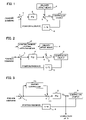
- FIG. 1 is a block diagram showing essential part of a servomotor driving controller according to a first embodiment of this invention
- FIG. 2 is a block diagram showing essential part of a servomotor driving controller according to a second embodiment of this invention
- FIG. 3 is a block diagram for explaining an arrangement for preparing velocity correction data by learning control for the first and second embodiments
- FIG. 4 is a block diagram for explaining another arrangement for preparing the velocity correction data
- FIG. 5 is a view for explaining an arrangement for obtaining a second velocity correction data by removing noise from the velocity correction data obtained by the learning control;
- FIG. 6 is a view for explaining an arrangement for obtaining a second velocity correction data by linearly approximating the velocity correction data obtained by the learning control;
- FIG. 7 is a block diagram of an arrangement for analyzing collected velocity correction data to obtain final velocity correction data
- FIG. 8 is a block diagram of an arrangement for preparing velocity correction data by using a friction model
- FIG. 9 is a block diagram of an arrangement for preparing velocity correction data not including noise by using the friction model
- FIG. 10 is a view for explaining normalized velocity correction data
- FIG. 11 is a view for explaining linearly approximated velocity correction data
- FIG. 12 is a flowchart of velocity correction processing in the first embodiment
- FIG. 13 is a flowchart of velocity correction processing in the second embodiment
- FIG. 14 is a flowchart of another velocity correction processing in the second embodiment
- FIG. 15 is a block diagram showing a servomotor control system according to a third embodiment in which a torque command is corrected to prevent a quadrant projection;
- FIG. 16 is a block diagram showing a servomotor control system according to a fourth embodiment in which a correction of torque command is performed to prevent a quadrant projection;
- FIG. 17 is a view for explaining an arrangement for preparing torque correction data in the third and fourth embodiments.
- FIGS. 18A through 18E are views showing results of experiments to evaluate effects of this invention.
- a servomotor driving controller comprises a subtractor 1 for determining a position deviation by subtracting a position feedback signal from a position command.
- the position feedback signal represents an actual position of a servomotor serving as a controlled object 5 , or of a movable part such as a table which is driven by the servomotor, and the position command is supplied from a host controller such as a numerical controller.
- the driving controller further comprises a multiplier 2 for determining a velocity command by multiplying the position deviation by a position gain Kp, and an adder 3 for determining a corrected velocity command by adding a correction amount, which is determined from correction data set beforehand in a velocity offset means 4 , to the velocity command.
- Reference numeral 6 denotes a position detecting section for determining an actual position of the controlled object 5 by integrating a velocity feedback signal supplied from a velocity detector attached to the controlled object 5 .
- FIG. 2 shows a servomotor driving controller according to a second embodiment of this invention, which differs from the first embodiment in that it comprises a position command reversal detection means 7 for detecting the sign of the position command being reversed and for outputting a correction start command to the velocity offset means 4 .
- the velocity offset means 4 adds a correction amount determined based on the velocity command data to a velocity command until a predetermined time period has elapsed from when the correction start command was output, to thereby determine a corrected velocity command with which the controlled object 5 is drivingly controlled.
- FIGS. 3 and 4 show how the velocity correction data to be stored in the velocity offset means 4 is prepared.
- a learning control is performed by means of a learning controller 10 additionally provided in the position loop control system of the controller, to thereby obtain a velocity command which is to be set to the velocity offset means 4 as the velocity correction data.
- a position deviation is determined by the subtractor 1 by subtracting the position feedback signal, indicative of an actual position of the controlled object 5 , from a position command supplied from the host controller, and the position deviation is stored in the learning controller 10 .
- the learning controller 10 determines a correction amount based on the one period old position deviation, and the adder 11 adds the correction amount to the position deviation to determine a corrected position deviation.
- the multiplier 2 multiplies the corrected position deviation by a position gain Kp to determine a velocity command used for the control of the drive of the controlled object 5 .
- the learning controller 10 may be a known one that comprises a storage section for storing pieces of data, indicative of position deviations that are determined at intervals of a predetermined cycle in a time period for which one pattern's position command are output in a case where the position command is repeatedly output in a pattern in order to machine workpieces into the same shape.
- the learning controller 10 adds the currently determined position deviation and the stored data indicative of the one pattern old position deviation together, and the resultant sum is stored as data of the present period after being subject to filtering.
- the one pattern old stored data is subject to dynamic characteristic compensation processing, and then output to be added to the position deviation.
- the position deviation converges to zero, if a set of instructions for machining a predetermined zone in which quadrant projection may be formed are repeatedly executed while performing the aforementioned learning control.
- the learning controller 10 corrects the position deviation.
- the corrected position deviation is multiplied by the position gain Kp to determine a velocity command for use as velocity correction data for the velocity offset means 4 .
- the velocity correction data can be regarded as a velocity command with which highly accurate machining can be made.
- the correction i.e., the addition of the velocity correction data to the velocity command, can produce effects similar to those obtainable by a feedforward control.
- the derivative of the position command is added to the velocity command to thereby compensate for a delay in position control attributable to a position gain, so that the position deviation becomes close to zero.
- the derivative of the position command can serve as an ideal velocity command, only if the velocity control system of the controller has an adequate following up characteristic. In case that the controlled object is highly affected by backlash, there occurs a rapid change in additional torque upon direction change to make it difficult to attain an adequate following up characteristic, so that the position deviation (quadrant projection) is caused.
- the learning control can produce an effect of sufficiently suppressing the formation of quadrant projection irrespective whether the following up performance of the velocity control system is adequate.
- the velocity command subject to the learning control before being output can practically be regarded as an ideal velocity command superior to that obtainable by the conventional feedforward control.
- the velocity correction data obtained by the method shown in FIG. 3 is equivalent to the ideal velocity command, and therefore, use of the velocity command corrected by the velocity correction data at the timing in phase with the learning control makes it possible to carry out machining with high shape accuracy.
- FIG. 4 is a block diagram for explaining another method for obtaining correction data.
- the example shown in FIG. 4 is common to the method of FIG. 3 in that the position command repeatedly instructed in the same pattern is subject to the learning control by the learning controller 10 , but differs in that it comprises a differentiating element 13 for differentiating the position command to obtain a commanded velocity, and a subtractor 12 for determining a velocity difference by subtracting the commanded velocity from a velocity command that is obtained by multiplying the corrected position deviation, which is obtained by the learning control, by the position gain Kp. After the position deviation is converged to zero by the learning control, the subtractor 12 subtracts the commanded velocity from the velocity command to determine the velocity difference that is to be used as the velocity correction data for the velocity offset means 4 .
- the derivative of the position command corresponding to the controlled variable in the feedforward control is subtracted from the velocity command obtained by the learning control, thereby collecting a disturbance compensating component of the velocity command obtained by the learning control.
- the disturbance compensating component (data) collected after the position command being reversed in sign can be regarded as being able to correct the quadrant projection caused by the presence of backlash.
- the velocity correction obtained based on such data can be applied to realize an optimum correction of the quadrant projection.
- the velocity correction data obtained as described above may be used as it is, however, the thus obtained correction data includes noise, and hence it is preferable that second correction data be prepared by removing the noise.
- FIG. 5 shows a method for preparing the second correction data, in which reference numeral 20 denotes velocity correction data collected in a zone where the moving direction changes and in a condition that the position deviation is converged to zero by means of the learning control.
- This velocity correction data 20 is shown as an example of ones determined from a difference between the commanded velocity shown in FIG. 4 and the actual velocity command.
- time and velocity correction data are taken along abscissa and ordinate, respectively, and the straight line extending from upper left to lower right denotes the velocity command.
- the correction data includes noise, and a large velocity difference is caused when the moving direction changes.
- the collected correction data is supplied to a filter 21 to remove noise components thereof, whereby the second correction data shown at 22 is obtained.
- the collected correction data 20 may be analyzed to obtain the second velocity correction data which is linearly approximated as shown at 23 .
- the one pattern's motion commands may be collected to be set, as velocity correction data, in the velocity offset means 4 .
- motion commands in a zone where the sign of motion command is reversed may be collected and analyzed in a manner as mentioned above to obtain analyzed data, and, for other zones, set data may be obtained which is comprised of collected motion commands or zero components.
- second velocity correction data comprised of the analyzed data and the set data may be set in the velocity offset means 4 .
- position commands are collected in the predetermined zone and stored as velocity correction data in the velocity offset means 4 .
- the velocity correction data obtained in the predetermined zone is analyzed to be stored as second velocity correction data in the velocity offset means 4 .
- the second correction data 22 or 23 analysis is made by using a host controller 30 or an external computer 31 , as shown in FIG. 7 .
- the collected correction data obtained by the method shown in FIG. 4 is transferred to the host controller 30 such as a numerical controller, and transferred from the host controller 30 to the computer 31 which carries out filtering or linear approximation to prepare the second correction data 22 or 23 .
- the correction data include, as shown in FIG.
- the correction data is normalized, in which a maximum correction amount is set to be 1 and a time period from start to end of the correction is set to be 1, as shown in FIG. 10 .
- the linearly approximated or normalized correction data i.e., the second correction data
- the second correction data may be prepared in the host controller 30 .
- the correction data is determined from the velocity command obtained by the learning control.
- the correction data may be determined by using a friction model at the time of the moving direction being changed.
- FIG. 8 an example of the friction model is shown at 32 , in which time and friction force are taken along abscissa and ordinate, respectively.
- the velocity correction data 24 is obtained by multiplying an output of the model 32 by an inverse function 33 of an open loop transfer function of the system for producing the torque command from the velocity command.
- the controller comprises a velocity controller for performing velocity loop control processing to determine a torque command (such as a velocity controller, mentioned later and shown in FIG. 15 , for performing velocity loop processing based on a velocity command supplied from the position loop system)
- the open loop transfer function (the transfer function of the velocity controller) and its inverse function are represented by Cv(S) and Cv(S) ⁇ 1 , respectively.
- the velocity correction data determined by using the friction model and the inverse function of the velocity controller, includes high frequency components which cause a fear of abruptly changing the correction amount, by extension the velocity command to which the correction amount is added.
- the high frequency components may be removed by using a filter 34 , thereby obtaining correction data 25 having a frequency zone to which the velocity control can follow up. In this case, a time delay is caused in the filtered correction data.
- the delay time is regarded as being equal to the rise time T, or is determined or estimated for example by calculating a phase delay at that maximum amplitude of input waveform to the filter 34 which is determined by means of frequency analysis.
- the filter 34 comprised of an M-th order FIR filter
- a delay about M/2 times as long as the sampling time is caused, and such delay is used as the delay time.
- the velocity correction data is set in the velocity offset means, with the correction data advanced with the delay time determined as described above.
- the velocity correction data is analyzed to obtain the linearly approximated correction data shown in FIG. 11 or the normalized correction data shown in FIG. 10 .
- Such velocity correction data is prepared by the host controller 30 or the external computer and delivered therefrom to the servomotor driving controller to be set in the feed velocity offset means 4 .
- FIG. 12 is a flowchart of the velocity correction processing shown in FIG. 1 and executed by a processor of the servomotor driving controller by using the aforementioned correction data.
- the processor of the controller executes the processing shown in FIG. 12 in every position loop processing period.
- a position deviation is determined based on a position command supplied from the host controller and a position feedback signal, and the position deviation is multiplied by the position gain Kp to determine a velocity command Vc (Step 100 ).
- Step 101 whether or not a flag F is set to 1 is determined (Step 101 ), and if not so, a determination is made as to whether a correction data reading command is input (Step 102 ). If such a command is not input, the flow proceeds to Step 109 which delivers the velocity command Vc determined at Step 100 to subsequent velocity loop control processing.
- Step 103 If the correction data reading command is input, a counter C is cleared and the flag F is set to 1 (Step 103 ). Then, the counter C is incremented by 1 (Step 104 ), and velocity correction data, corresponding to a value stored in the counter C and serving as a correction amount A, is read from a storage section in which pieces of velocity correction data are stored (Step 105 ). The correction amount A is added to the velocity command Vc determined at Step 100 , thereby obtaining a corrected velocity command Vc (Step 106 ). Next, a determination is made as to whether the counter value reaches a preset value C 0 indicative of the end of a zone in which the velocity command is to be corrected (Step 107 ). If the preset value C 0 is not reached, the flow proceeds to Step 109 which outputs the corrected velocity command Vc.
- Step 101 the flow proceeds from Step 101 to Step 104 after completion of the position loop processing to determine the velocity command Vc at Step 100 .
- the processing at Steps 104 – 109 is performed so that the velocity command Vc determined by the position loop processing is corrected by using the velocity correction data stored in the velocity offset means.
- the corrected velocity command Vc serves as velocity command for the next velocity loop processing, etc.
- Step 107 the flag F is reset to 0 (Step 108 ) and the flow proceeds to Step 109 .
- the processing of Steps 100 – 102 and 109 is repeatedly executed until the correction data reading command is input again.
- the velocity command correction based on velocity correction data is performed over the predetermined zone from when the correction data reading command is input, whereby a quadrant projection is suppressed from being formed, thus realizing highly accurate machining.
- FIG. 13 is a flowchart of processing executed by the processor of the servomotor driving controller to embody the method shown in FIG. 2 .
- the correction data that is normalized for a moving direction reversal zone as shown in FIG. 10 is used as velocity correction data.
- the position loop processing is performed to determine a velocity command Vc (Step 200 ).
- the velocity command Vc is obtained by determining a position deviation between a position command and a position feedback signal and by multiplying the position deviation by a position gain.
- Step 201 whether a flag F is set to 1 is determined, and if not so, a further determination is made as to whether or not the sign of the position command supplied from the host controller, the moving direction, is reversed (Step 202 ). If the sign or direction is not reversed, the flow proceeds to Step 211 which delivers the velocity command Vc obtained at Step 200 to the next processing (such as velocity loop processing).
- Step 202 if it is determined at Step 202 that the sign of the position command from the host controller, and by extension the quadrant to which the machining position belongs, is reversed, a further determination is made as to whether the velocity command determined by the position loop processing at Step 200 is less than a preset velocity V 0 (Step 204 ). If not so, the flow proceeds to Step 210 . If the velocity command is less than the preset value V 0 , the flag F is set to 1 (Step 205 ), and the counter C is reset (Step 206 ).
- Step 207 the counter C is incremented by 1 (Step 207 ), and a correction amount A is determined by multiplying a value of velocity correction data, corresponding to the value of the counter C, by a proportional coefficient A 0 .
- the correction amount A is added to the velocity command Vc determined at Step 200 , thereby obtaining a new, corrected velocity command (Step 208 ).
- Step 209 a determination is made as to whether the value of the counter C is equal to or larger than a value C 0 that is set beforehand so as to correspond to a correction time period (Step 209 ), the preset value C 0 indicating the number of position loop processing periods included in the correction time period. If the counter value does not reach the preset value C 0 , the flow proceeds to Step 211 which delivers the corrected velocity command Vc obtained at Step 208 .
- Step 201 the flow proceeds from Step 201 to Step 207 to determine a correction amount A, which is added to the velocity command obtained by the position loop processing, to obtain and output a corrected velocity command.
- Steps 200 , 201 , 207 – 209 , and 211 is repeatedly performed to determine a corrected velocity command by adding a correction amount determined based on correction data to a velocity command determined by the position loop processing.
- Step 209 the flow proceeds from Step 209 to Step 210 which resets the flag F to 0, and then proceeds to Step 211 which outputs the corrected velocity command obtained at Step 208 .
- Step 202 since the flag F has been reset to 0, the above-described processing is executed, in which the velocity command correction based on velocity correction data is performed for the predetermined zone, after the velocity command becomes less than the predetermined value subsequent to the reversal of the sign of the position command or the moving direction command, whereby the fear of a projection being formed upon quadrant change is reduced.
- the processing shown in FIG. 13 is executed in case that the correction data shown in FIG. 10 is stored in the memory (velocity offset means) of the servomotor driving controller.
- the processing shown in FIG. 14 is executed, in which the processing of Steps 300 – 305 which is the same as that of Steps 200 – 205 of FIG. 13 is executed, and then the processing of Steps 306 – 315 different from that of Steps 206 – 211 is executed.
- Steps 300 – 304 and 315 is carried out in every position loop processing period before the sign of position command is reversed and the velocity command Vc becomes less than the predetermined value V 0 , so that the velocity command Vc determined by normal position loop processing (Step 300 ) is output.
- the controller processor causes a timer t to be reset and started again (Step 306 ), and determines whether a time period measured by the timer t is equal to or less than a first preset time t 1 , which is stored in advance as velocity correction data (Step 307 ).
- a correction amount A 0 stored corresponding to the preset time t 1 is multiplied by a time ratio t/t 1 to determine a correction amount A, and a corrected velocity command is determined by adding the correction amount A to the velocity command Vc determined at Step 300 (Step 308 ).
- the correction amount A is added to the velocity command Vc obtained at Step 300 , whereby a corrected velocity command is determined (Step 310 ).
- the correction amount A is then added to the velocity command Vc obtained at Step 300 , whereby a corrected velocity command is determined (Step 312 ).
- the corrected velocity command is delivered to the next processing.(such as velocity loop processing or electric current loop processing).
- Step 313 If the measured time t exceeds the third preset time t 3 indicative the end of the correction time period (Step 313 ), the flag F is reset to 0 (Step 314 ), and the flow proceeds to Step 315 .
- the velocity command is corrected based on correction data, to prevent the quadrant projection.
- the quadrant projection is prevented by the velocity command correction in the embodiments, it is also possible to prevent the quadrant projection by correcting the torque command.
- FIG. 15 is a block diagram of a servomotor control system according to a third embodiment, in which the torque command is corrected in order to prevent the quadrant projection.
- the third embodiment shown in FIG. 15 differs from the embodiment shown in FIG. 1 in that a velocity controller 14 is additionally provided, and a torque offset means 15 for adding a torque correction amount to a torque command output from the velocity controller 14 is provided instead of the velocity offset means 4 .
- a position deviation is determined by the subtractor 1 in which a position feedback signal, indicative of an actual position of the servomotor serving as the controlled object 5 or of a movable part of a table, etc. driven by the servomotor, is subtracted from a position command supplied from the host controller.
- the position deviation is multiplied by the position gain Kp in the multiplier 2 to determine a velocity command from which a velocity feedback signal is subtracted in the subtractor 16 to determine a velocity deviation that is supplied to the velocity controller 14 in which the velocity deviation is subject to a PI (proportional integral) control, etc. to determine a torque command, whereas a torque correction amount is determined from torque correction data set in advance in the torque offset means 15 .
- the torque correction amount is added to the torque command to thereby determine a corrected torque command with which the servomotor serving as the controlled object 5 is driven, whereby a quadrant projection is prevented.
- FIG. 16 is a block diagram showing a fourth embodiment-which differs from the third embodiment shown in FIG. 15 in that reversal detection means 7 is provided which detects the sign of position command being reversed and which outputs a correction start command to the torque offset means 15 . Until a predetermined time period has elapsed from when the correction start command was output from the reversal detection means 7 , a torque correction amount determined based on the preset torque correction data is added to the torque command to determine a corrected torque command with which the servomotor serving as controlled object is drivingly controlled.
- FIG. 17 is a block diagram showing a method for preparing the torque correction data, which method differs from the method shown in FIG. 4 for determining velocity correction amount in that a velocity controller 14 is additionally provided, and a second order differentiating element 18 for subjecting the position command to second order differentiation to determine acceleration is used instead of the differential element 13 for differentiating the position command.
- the learning controller 10 comprises a storage section for storing pieces of data corresponding to position deviations, which are determined at intervals of a predetermined period in a time period for which one pattern's position commands are output.
- the position deviation determined in the present period is added to data that was determined and stored on the basis of one pattern old position deviation, and the resultant sum is subject to filtering and then stored as data of the present period.
- the stored data of one pattern period old is subject to dynamic characteristic compensation processing, and is then output to be added to the position deviation.
- a position deviation is determined by means of the subtractor 1 in which a position feedback signal, indicative of an actual position of the controlled object 5 , is subtracted in the subtractor 1 from a position command supplied from the host controller.
- This position deviation is stored in the learning controller 10 .
- a correction amount determined based on a one period old position deviation is added to the position deviation, thereby deter a corrected position deviation which is then multiplied by a position gain Kp in the multiplier 2 , to determine a velocity command from which a velocity feedback amount is subtracted in the subtractor 16 to determine a velocity deviation.
- velocity loop processing is performed by the velocity controller 14 to determine a torque command (acceleration command) with which the controlled object 5 is drivingly controlled.
- the position deviation converges to zero, if a set of commands for machining a predetermined zone in which a quadrant projection may be formed are repeatedly executed while performing the leaning control.
- the learning controller 10 corrects the position deviation, and the corrected position deviation is multiplied by the position gain Kp to determine a velocity command.
- Velocity loop control processing is performed by the velocity controller 14 to determine a torque command based on the velocity command and a velocity feedback signal, whereas a commanded acceleration is determined by the second order differentiating element 18 by subjecting the position command to second order differentiation.
- the subtractor 19 the commanded acceleration is subtracted from the torque command to thereby determine a difference therebetween which is set as torque correction data in the torque offset means.
- the torque correction data determined from the difference between the torque command and the commanded acceleration may be subject to filtering to remove noise, so that the resultant data may serve as a second torque correction data.
- the torque correction data may be linearly approximated to obtain a second torque correction data.
- the torque correction data is normalized or linearly approximated, so as to be in the same form as the velocity correction data.
- the torque correction data is stored in the torque offset means 15 for use in correcting the torque command for prevention of occurrence of a quadrant projection.
- a servomotor driving controller In a servomotor driving controller according to an embodiment which corrects the torque command so as to prevent a quadrant projection, processing (not shown) is performed for every position/velocity loop processing period, which processing is substantially the same as that shown in FIGS. 12–14 , but differs in the following points: Position loop processing to determine the velocity command is performed, and velocity loop processing to determine the torque command is performed based on the velocity command and velocity feedback signal, as conventionally known in a step corresponding to Step 100 , 200 or 300 (illustration of this step and below-mentioned steps are omitted), a correction amount A is determined based on the torque correction data at a step corresponding to Step 105 , 208 , 308 , 310 or 312 , this torque correction data is added to the torque command determined in a step corresponding to Step 100 , 200 or 300 , thereby determining a corrected torque command, and the corrected torque is output in a step corresponding to Step 109 , 211 or 315
- FIGS. 18A through 18E are views showing results of experiments conducted to evaluate effects of this invention, in which errors in circular arc cutting are indicated in units of 2 ⁇ m, and the indication of errors in regions each enclosed by a circle are given at greater magnification.
- FIG. 18A indicates errors in case that no correction to reduce a quadrant projection is made
- FIG. 18B indicates errors in the case of a conventional correction to reduce a quadrant projection being made
- FIG. 18C indicates errors in the case of a learning control being made
- FIGS. 18D , 18 E indicate errors in the first and second embodiments of this invention, respectively.
- the quadrant projection (the error relative to the command) that is formed in a machined surface upon quadrant change becomes greatest when no quadrant projection correction is made ( FIG. 18A ), and it becomes the next greatest when the conventional quadrant projection correction is applied ( FIG. 18B ).
- the quadrant projection is reduced.
- FIGS. 18D and 18E there occurs substantially no quadrant projection, resulting in machining accuracy that is equivalent to the accuracy observed when the quadrant is kept unchanged.
Abstract
Description
A=A0+(A1−A0)×(t−t1)/(t2−t1)
A=A1+(A2−A1)×(t−t2)/(t3−t2)
Claims (13)
Applications Claiming Priority (2)
| Application Number | Priority Date | Filing Date | Title |
|---|---|---|---|
| JP22102/2003 | 2003-01-30 | ||
| JP2003022102A JP3805309B2 (en) | 2003-01-30 | 2003-01-30 | Servo motor drive control device |
Publications (2)
| Publication Number | Publication Date |
|---|---|
| US20040183495A1 US20040183495A1 (en) | 2004-09-23 |
| US7084596B2 true US7084596B2 (en) | 2006-08-01 |
Family
ID=32652891
Family Applications (1)
| Application Number | Title | Priority Date | Filing Date |
|---|---|---|---|
| US10/767,058 Expired - Lifetime US7084596B2 (en) | 2003-01-30 | 2004-01-30 | Servomotor driving controller |
Country Status (5)
| Country | Link |
|---|---|
| US (1) | US7084596B2 (en) |
| EP (1) | EP1443372B1 (en) |
| JP (1) | JP3805309B2 (en) |
| CN (1) | CN100449933C (en) |
| DE (1) | DE602004004177T2 (en) |
Cited By (12)
| Publication number | Priority date | Publication date | Assignee | Title |
|---|---|---|---|---|
| US20060173573A1 (en) * | 2005-02-02 | 2006-08-03 | Fanuc Ltd | Numerical controller |
| US20070007927A1 (en) * | 2004-07-29 | 2007-01-11 | Mitsubishi Denki Kabushiki Kaisha | Position controller and controlling method therefor |
| US20130173026A1 (en) * | 2010-10-27 | 2013-07-04 | Makino Millling Machine Co., Ltd. | Numerical control method |
| US9119655B2 (en) | 2012-08-03 | 2015-09-01 | Stryker Corporation | Surgical manipulator capable of controlling a surgical instrument in multiple modes |
| US9226796B2 (en) | 2012-08-03 | 2016-01-05 | Stryker Corporation | Method for detecting a disturbance as an energy applicator of a surgical instrument traverses a cutting path |
| US9480534B2 (en) | 2012-08-03 | 2016-11-01 | Stryker Corporation | Navigation system and method for removing a volume of tissue from a patient |
| US20170166240A1 (en) * | 2015-12-14 | 2017-06-15 | Hyundai Motor Company | System for compensating for disturbance of motor for motor driven power steering |
| US9820818B2 (en) | 2012-08-03 | 2017-11-21 | Stryker Corporation | System and method for controlling a surgical manipulator based on implant parameters |
| US9921712B2 (en) | 2010-12-29 | 2018-03-20 | Mako Surgical Corp. | System and method for providing substantially stable control of a surgical tool |
| US10108177B2 (en) | 2015-06-18 | 2018-10-23 | Mitsubishi Electric Corporation | Control parameter adjustment device |
| US20200336093A1 (en) * | 2015-07-22 | 2020-10-22 | Texas Instruments Incorporated | Adaptive Torque Disturbance Cancellation for Electric Motors |
| US11202682B2 (en) | 2016-12-16 | 2021-12-21 | Mako Surgical Corp. | Techniques for modifying tool operation in a surgical robotic system based on comparing actual and commanded states of the tool relative to a surgical site |
Families Citing this family (28)
| Publication number | Priority date | Publication date | Assignee | Title |
|---|---|---|---|---|
| JP3739749B2 (en) * | 2003-01-07 | 2006-01-25 | ファナック株式会社 | Control device |
| JP3805309B2 (en) * | 2003-01-30 | 2006-08-02 | ファナック株式会社 | Servo motor drive control device |
| JP2006039807A (en) * | 2004-07-26 | 2006-02-09 | Fanuc Ltd | Numerical control device |
| JP4283214B2 (en) | 2004-12-16 | 2009-06-24 | ファナック株式会社 | Machine tip control device |
| JP5256619B2 (en) * | 2007-02-23 | 2013-08-07 | ブラザー工業株式会社 | Motor drive device and image forming apparatus |
| JP5156886B2 (en) * | 2007-03-02 | 2013-03-06 | 富士機械製造株式会社 | Position control device |
| JP4838817B2 (en) * | 2008-01-09 | 2011-12-14 | 三菱重工業株式会社 | Lost motion elimination control device |
| JP5139164B2 (en) * | 2008-06-10 | 2013-02-06 | オークマ株式会社 | Position control device |
| JP4741637B2 (en) * | 2008-06-30 | 2011-08-03 | ファナック株式会社 | Servo motor drive control device and drive control method |
| JP4620148B2 (en) * | 2008-10-15 | 2011-01-26 | ファナック株式会社 | Servo motor control device |
| JP4575508B1 (en) | 2009-05-20 | 2010-11-04 | ファナック株式会社 | Servo control device for dual position feedback control |
| JP4620159B2 (en) * | 2009-05-21 | 2011-01-26 | ファナック株式会社 | Servo motor control device that controls periodic reciprocating motion |
| JP4927985B1 (en) * | 2010-11-22 | 2012-05-09 | ファナック株式会社 | Drive control apparatus for servo motor having at least two feed axes orthogonal to each other for moving table or tool of machine tool |
| JP5732289B2 (en) * | 2011-03-22 | 2015-06-10 | オークマ株式会社 | Machine Tools |
| JP5852467B2 (en) * | 2012-02-23 | 2016-02-03 | オークマ株式会社 | Numerical controller |
| JP5252102B1 (en) * | 2012-04-03 | 2013-07-31 | 株式会社安川電機 | Motor control device, motor control system, and cutting device |
| US9772619B2 (en) * | 2014-01-23 | 2017-09-26 | Mitsubishi Electric Corporation | Motor control device |
| TWI558495B (en) | 2014-11-12 | 2016-11-21 | 財團法人工業技術研究院 | Machining assistance method and the apparatus using the same |
| JP6366563B2 (en) * | 2014-12-19 | 2018-08-01 | オークマ株式会社 | Position control device of feed axis in machine tool |
| KR102343572B1 (en) * | 2015-03-06 | 2021-12-28 | 삼성디스플레이 주식회사 | Organic light emitting device |
| JP6469069B2 (en) * | 2016-12-13 | 2019-02-13 | ファナック株式会社 | Robot control apparatus and robot control method having function for facilitating learning |
| JP6834528B2 (en) * | 2017-01-25 | 2021-02-24 | オムロン株式会社 | Control devices, control programs and control systems |
| JP6742943B2 (en) * | 2017-04-17 | 2020-08-19 | Dmg森精機株式会社 | Machine tool feeding control device |
| CN107659221A (en) * | 2017-08-30 | 2018-02-02 | 杭州为诺智能科技有限公司 | A kind of multi- drive synchronization system based on RS485 bus marcos |
| CN110023857B (en) * | 2017-11-10 | 2020-06-16 | 三菱电机株式会社 | Servo control device |
| US10613511B2 (en) | 2017-12-22 | 2020-04-07 | Industrial Technology Research Institute | Tool machine servo control simulation device and establishing method of structure model |
| CN108501768B (en) * | 2018-03-29 | 2021-05-07 | 南京航空航天大学 | Two-wheel speed control method based on Z-axis gyroscope and wheel speed difference |
| DE102019002644A1 (en) | 2018-04-17 | 2019-10-17 | Fanuc Corporation | Control and control procedures |
Citations (32)
| Publication number | Priority date | Publication date | Assignee | Title |
|---|---|---|---|---|
| EP0292574A1 (en) | 1986-12-12 | 1988-11-30 | Fanuc Ltd. | Numerical controller |
| EP0389641A1 (en) | 1988-09-30 | 1990-10-03 | Fanuc Ltd. | Servo controller |
| US5059881A (en) * | 1989-12-28 | 1991-10-22 | Toshiba Kikai Kabushiki Kaisha | Numerical control apparatus having a backlash compensation function and method thereof |
| US5153490A (en) * | 1990-03-20 | 1992-10-06 | Toshiba Kikai Kabushiki Kaisha | Numerical control apparatus of machines |
| EP0540761A1 (en) | 1991-05-24 | 1993-05-12 | Fanuc Ltd. | Method of controlling backlash acceleration |
| EP0547239A1 (en) | 1991-07-04 | 1993-06-23 | Fanuc Ltd. | Back-lash acceleration control method |
| JPH07110717A (en) | 1993-08-19 | 1995-04-25 | Fanuc Ltd | Motor control system |
| US5517100A (en) | 1993-04-28 | 1996-05-14 | Fanuc Ltd. | Method of controlling a servo motor |
| EP0752754A1 (en) * | 1995-07-04 | 1997-01-08 | Samsung Electronics Co., Ltd. | Method for controlling velocity of rotary motor and apparatus therefor |
| US5710498A (en) * | 1994-12-06 | 1998-01-20 | Trinova Corporation | Method and apparatus for friction compensation |
| JPH1056791A (en) * | 1996-04-30 | 1998-02-24 | Samsung Electron Co Ltd | Speed control apparatus for rotating motor |
| US5767645A (en) * | 1995-07-13 | 1998-06-16 | Lg Industrial Systems Co., Ltd. | Backlash correction apparatus and method of numerical controller |
| US5773938A (en) * | 1995-07-04 | 1998-06-30 | Samsung Electronics Co., Ltd. | Apparatus for controlling speed of a rotary motor |
| JPH10268916A (en) | 1997-03-21 | 1998-10-09 | Fanuc Ltd | Method for correcting position at time of inverting moving direction |
| US5880566A (en) * | 1996-07-19 | 1999-03-09 | Samsung Electronics Co., Ltd. | Absolute angular position calculation apparatus for a rotating motor and velocity control apparatus adopting the same |
| US5907450A (en) * | 1995-11-24 | 1999-05-25 | Nec Corporation | Pre-read learning digital servo-control device |
| US6046566A (en) * | 1998-04-21 | 2000-04-04 | Fanuc Ltd. | Method of and apparatus for controlling a plurality of servomotors |
| US20010002097A1 (en) * | 1999-05-14 | 2001-05-31 | Kazuhiko Tsutsui | Servo control apparatus |
| US6252368B1 (en) * | 1998-12-28 | 2001-06-26 | Mitsubishi Denki Kabushiki Kaisha | Numerically controlled system and backlash compensation device for use with the system |
| WO2001088649A1 (en) | 2000-05-15 | 2001-11-22 | Kabushiki Kaisha Yaskawa Denki | Positioning servocontroller |
| EP1184766A1 (en) | 1999-06-04 | 2002-03-06 | Kabushiki Kaisha Yaskawa Denki Seisakusho | Position controller for motor |
| US6437534B1 (en) * | 1999-09-10 | 2002-08-20 | Yoshiaki Kakino | Control method for NC machine tool |
| GB2373066A (en) | 2000-11-01 | 2002-09-11 | Mitsubishi Electric Corp | Servo controller and method |
| JP2002258922A (en) | 2001-03-01 | 2002-09-13 | Mitsubishi Electric Corp | Numeric control system |
| US6472842B1 (en) * | 1997-10-03 | 2002-10-29 | The Texas A&M University System | Self-tuning control of switched-reluctance motor drive system |
| US20030016607A1 (en) * | 2001-06-20 | 2003-01-23 | Samsung Electronics Co., Ltd. | Disk drive servo system for eccentricity compensation and method thereof |
| US6686716B1 (en) * | 2001-07-18 | 2004-02-03 | Itt Manufacturing Enterprises, Inc. | Tuned open-loop switched to closed-loop method for rapid point-to-point movement of a periodic motion control system |
| US6721247B2 (en) * | 2000-07-10 | 2004-04-13 | Fujitsu Limited | Disk apparatus and track following control method |
| US20040145333A1 (en) * | 2003-01-20 | 2004-07-29 | Fanuc Ltd. | Servo motor drive control device |
| US20040150363A1 (en) * | 2003-01-21 | 2004-08-05 | Fanuc Ltd. | Servo controller |
| US20040183495A1 (en) * | 2003-01-30 | 2004-09-23 | Fanuc Ltd. | Servomotor driving controller |
| US6845068B2 (en) * | 2001-09-12 | 2005-01-18 | Fujitsu Limited | Optical disk apparatus and focus control method thereof |
-
2003
- 2003-01-30 JP JP2003022102A patent/JP3805309B2/en not_active Expired - Fee Related
-
2004
- 2004-01-28 DE DE602004004177T patent/DE602004004177T2/en not_active Expired - Lifetime
- 2004-01-28 EP EP04250450A patent/EP1443372B1/en not_active Expired - Fee Related
- 2004-01-30 US US10/767,058 patent/US7084596B2/en not_active Expired - Lifetime
- 2004-01-30 CN CNB2004100393524A patent/CN100449933C/en not_active Expired - Fee Related
Patent Citations (39)
| Publication number | Priority date | Publication date | Assignee | Title |
|---|---|---|---|---|
| EP0292574A1 (en) | 1986-12-12 | 1988-11-30 | Fanuc Ltd. | Numerical controller |
| EP0389641A1 (en) | 1988-09-30 | 1990-10-03 | Fanuc Ltd. | Servo controller |
| US5059881A (en) * | 1989-12-28 | 1991-10-22 | Toshiba Kikai Kabushiki Kaisha | Numerical control apparatus having a backlash compensation function and method thereof |
| US5153490A (en) * | 1990-03-20 | 1992-10-06 | Toshiba Kikai Kabushiki Kaisha | Numerical control apparatus of machines |
| EP0540761A1 (en) | 1991-05-24 | 1993-05-12 | Fanuc Ltd. | Method of controlling backlash acceleration |
| US5367238A (en) * | 1991-05-24 | 1994-11-22 | Fanuc Ltd. | Backlash acceleration control method |
| EP0547239A1 (en) | 1991-07-04 | 1993-06-23 | Fanuc Ltd. | Back-lash acceleration control method |
| US5517100A (en) | 1993-04-28 | 1996-05-14 | Fanuc Ltd. | Method of controlling a servo motor |
| JPH07110717A (en) | 1993-08-19 | 1995-04-25 | Fanuc Ltd | Motor control system |
| US5598077A (en) | 1993-08-19 | 1997-01-28 | Fanuc Ltd. | Control apparatus and a control method for a servomotor |
| US5710498A (en) * | 1994-12-06 | 1998-01-20 | Trinova Corporation | Method and apparatus for friction compensation |
| EP0752754A1 (en) * | 1995-07-04 | 1997-01-08 | Samsung Electronics Co., Ltd. | Method for controlling velocity of rotary motor and apparatus therefor |
| US5666034A (en) * | 1995-07-04 | 1997-09-09 | Samsung Electronics Co., Ltd. | Method for controlling velocity of a rotary motor and an apparatus therefor |
| US5773938A (en) * | 1995-07-04 | 1998-06-30 | Samsung Electronics Co., Ltd. | Apparatus for controlling speed of a rotary motor |
| US5767645A (en) * | 1995-07-13 | 1998-06-16 | Lg Industrial Systems Co., Ltd. | Backlash correction apparatus and method of numerical controller |
| US5907450A (en) * | 1995-11-24 | 1999-05-25 | Nec Corporation | Pre-read learning digital servo-control device |
| JPH1056791A (en) * | 1996-04-30 | 1998-02-24 | Samsung Electron Co Ltd | Speed control apparatus for rotating motor |
| US5880566A (en) * | 1996-07-19 | 1999-03-09 | Samsung Electronics Co., Ltd. | Absolute angular position calculation apparatus for a rotating motor and velocity control apparatus adopting the same |
| EP0913749A1 (en) | 1997-03-21 | 1999-05-06 | Fanuc Ltd | Shift command correction method and servo control system in which shift command is corrected |
| US6107771A (en) * | 1997-03-21 | 2000-08-22 | Fanuc Ltd. | Move command correction method and servo control system with correction of move command |
| JPH10268916A (en) | 1997-03-21 | 1998-10-09 | Fanuc Ltd | Method for correcting position at time of inverting moving direction |
| US6472842B1 (en) * | 1997-10-03 | 2002-10-29 | The Texas A&M University System | Self-tuning control of switched-reluctance motor drive system |
| US6046566A (en) * | 1998-04-21 | 2000-04-04 | Fanuc Ltd. | Method of and apparatus for controlling a plurality of servomotors |
| US6252368B1 (en) * | 1998-12-28 | 2001-06-26 | Mitsubishi Denki Kabushiki Kaisha | Numerically controlled system and backlash compensation device for use with the system |
| US20010002097A1 (en) * | 1999-05-14 | 2001-05-31 | Kazuhiko Tsutsui | Servo control apparatus |
| EP1184766A1 (en) | 1999-06-04 | 2002-03-06 | Kabushiki Kaisha Yaskawa Denki Seisakusho | Position controller for motor |
| US6437534B1 (en) * | 1999-09-10 | 2002-08-20 | Yoshiaki Kakino | Control method for NC machine tool |
| WO2001088649A1 (en) | 2000-05-15 | 2001-11-22 | Kabushiki Kaisha Yaskawa Denki | Positioning servocontroller |
| US6784632B2 (en) | 2000-05-15 | 2004-08-31 | Kabushiki Kaisha Yaskawa Denki | Positioning servo controller |
| US6721247B2 (en) * | 2000-07-10 | 2004-04-13 | Fujitsu Limited | Disk apparatus and track following control method |
| GB2373066A (en) | 2000-11-01 | 2002-09-11 | Mitsubishi Electric Corp | Servo controller and method |
| JP2002258922A (en) | 2001-03-01 | 2002-09-13 | Mitsubishi Electric Corp | Numeric control system |
| US20030016607A1 (en) * | 2001-06-20 | 2003-01-23 | Samsung Electronics Co., Ltd. | Disk drive servo system for eccentricity compensation and method thereof |
| US6686716B1 (en) * | 2001-07-18 | 2004-02-03 | Itt Manufacturing Enterprises, Inc. | Tuned open-loop switched to closed-loop method for rapid point-to-point movement of a periodic motion control system |
| US6845068B2 (en) * | 2001-09-12 | 2005-01-18 | Fujitsu Limited | Optical disk apparatus and focus control method thereof |
| US20040145333A1 (en) * | 2003-01-20 | 2004-07-29 | Fanuc Ltd. | Servo motor drive control device |
| US6859007B2 (en) * | 2003-01-20 | 2005-02-22 | Fanuc Ltd | Servo motor drive control device |
| US20040150363A1 (en) * | 2003-01-21 | 2004-08-05 | Fanuc Ltd. | Servo controller |
| US20040183495A1 (en) * | 2003-01-30 | 2004-09-23 | Fanuc Ltd. | Servomotor driving controller |
Non-Patent Citations (2)
| Title |
|---|
| Communication and European Search Report dated Sep. 13, 2005 (8 pages). |
| Notification of Decision of Rejection; Ref. No. 2164OP; Dispatch No. 493490; Dispatch Date Jan. 10, 2006 for Patent Application No. 022102/2003. |
Cited By (32)
| Publication number | Priority date | Publication date | Assignee | Title |
|---|---|---|---|---|
| US20070007927A1 (en) * | 2004-07-29 | 2007-01-11 | Mitsubishi Denki Kabushiki Kaisha | Position controller and controlling method therefor |
| US7560890B2 (en) * | 2004-07-29 | 2009-07-14 | Mitsubishi Denki Kabushiki Kaisha | Position controller and controlling method therefor |
| US7206659B2 (en) * | 2005-02-02 | 2007-04-17 | Fanuc Ltd | Numerical controller |
| US20060173573A1 (en) * | 2005-02-02 | 2006-08-03 | Fanuc Ltd | Numerical controller |
| US9360849B2 (en) * | 2010-10-27 | 2016-06-07 | Makino Milling Machine Co., Ltd. | Numerical control method |
| US20130173026A1 (en) * | 2010-10-27 | 2013-07-04 | Makino Millling Machine Co., Ltd. | Numerical control method |
| US9921712B2 (en) | 2010-12-29 | 2018-03-20 | Mako Surgical Corp. | System and method for providing substantially stable control of a surgical tool |
| US11045958B2 (en) | 2012-08-03 | 2021-06-29 | Stryker Corporation | Surgical robotic system and method for commanding instrument position based on iterative boundary evaluation |
| US10420619B2 (en) | 2012-08-03 | 2019-09-24 | Stryker Corporation | Surgical manipulator and method for transitioning between operating modes |
| US9566122B2 (en) | 2012-08-03 | 2017-02-14 | Stryker Corporation | Robotic system and method for transitioning between operating modes |
| US9566125B2 (en) | 2012-08-03 | 2017-02-14 | Stryker Corporation | Surgical manipulator having a feed rate calculator |
| US11672620B2 (en) | 2012-08-03 | 2023-06-13 | Stryker Corporation | Robotic system and method for removing a volume of material from a patient |
| US9681920B2 (en) | 2012-08-03 | 2017-06-20 | Stryker Corporation | Robotic system and method for reorienting a surgical instrument moving along a tool path |
| US9795445B2 (en) | 2012-08-03 | 2017-10-24 | Stryker Corporation | System and method for controlling a manipulator in response to backdrive forces |
| US9820818B2 (en) | 2012-08-03 | 2017-11-21 | Stryker Corporation | System and method for controlling a surgical manipulator based on implant parameters |
| US9226796B2 (en) | 2012-08-03 | 2016-01-05 | Stryker Corporation | Method for detecting a disturbance as an energy applicator of a surgical instrument traverses a cutting path |
| US11639001B2 (en) | 2012-08-03 | 2023-05-02 | Stryker Corporation | Robotic system and method for reorienting a surgical instrument |
| US11471232B2 (en) | 2012-08-03 | 2022-10-18 | Stryker Corporation | Surgical system and method utilizing impulse modeling for controlling an instrument |
| US10314661B2 (en) | 2012-08-03 | 2019-06-11 | Stryker Corporation | Surgical robotic system and method for controlling an instrument feed rate |
| US10350017B2 (en) | 2012-08-03 | 2019-07-16 | Stryker Corporation | Manipulator and method for controlling the manipulator based on joint limits |
| US9480534B2 (en) | 2012-08-03 | 2016-11-01 | Stryker Corporation | Navigation system and method for removing a volume of tissue from a patient |
| US10426560B2 (en) | 2012-08-03 | 2019-10-01 | Stryker Corporation | Robotic system and method for reorienting a surgical instrument moving along a tool path |
| US10463440B2 (en) | 2012-08-03 | 2019-11-05 | Stryker Corporation | Surgical manipulator and method for resuming semi-autonomous tool path position |
| US11179210B2 (en) | 2012-08-03 | 2021-11-23 | Stryker Corporation | Surgical manipulator and method for controlling pose of an instrument based on virtual rigid body modelling |
| US9119655B2 (en) | 2012-08-03 | 2015-09-01 | Stryker Corporation | Surgical manipulator capable of controlling a surgical instrument in multiple modes |
| US10108177B2 (en) | 2015-06-18 | 2018-10-23 | Mitsubishi Electric Corporation | Control parameter adjustment device |
| US20200336093A1 (en) * | 2015-07-22 | 2020-10-22 | Texas Instruments Incorporated | Adaptive Torque Disturbance Cancellation for Electric Motors |
| US11515822B2 (en) * | 2015-07-22 | 2022-11-29 | Texas Instruments Incorporated | Adaptive torque disturbance cancellation for electric motors |
| US10167011B2 (en) * | 2015-12-14 | 2019-01-01 | Hyundai Motor Company | System for compensating for disturbance of motor for motor driven power steering |
| US20170166240A1 (en) * | 2015-12-14 | 2017-06-15 | Hyundai Motor Company | System for compensating for disturbance of motor for motor driven power steering |
| US11202682B2 (en) | 2016-12-16 | 2021-12-21 | Mako Surgical Corp. | Techniques for modifying tool operation in a surgical robotic system based on comparing actual and commanded states of the tool relative to a surgical site |
| US11850011B2 (en) | 2016-12-16 | 2023-12-26 | Mako Surgical Corp. | Techniques for modifying tool operation in a surgical robotic system based on comparing actual and commanded states of the tool relative to a surgical site |
Also Published As
| Publication number | Publication date |
|---|---|
| EP1443372B1 (en) | 2007-01-10 |
| JP3805309B2 (en) | 2006-08-02 |
| EP1443372A3 (en) | 2006-01-04 |
| CN100449933C (en) | 2009-01-07 |
| DE602004004177T2 (en) | 2007-04-19 |
| EP1443372A2 (en) | 2004-08-04 |
| DE602004004177D1 (en) | 2007-02-22 |
| US20040183495A1 (en) | 2004-09-23 |
| CN1520025A (en) | 2004-08-11 |
| JP2004234327A (en) | 2004-08-19 |
Similar Documents
| Publication | Publication Date | Title |
|---|---|---|
| US7084596B2 (en) | Servomotor driving controller | |
| JP4581096B2 (en) | Friction compensation method, friction compensator, and motor control device | |
| EP2634657B1 (en) | Numerical control method | |
| EP1439440A2 (en) | Servo motor drive control device | |
| EP0012620B1 (en) | Closed loop type numerical-controlled machine tool | |
| EP1667001B1 (en) | Controller | |
| JP3739749B2 (en) | Control device | |
| US8098038B2 (en) | Servomotor control system enabling high-speed oscillating motion to be highly precise | |
| JP3129622B2 (en) | Quadrant projection correction method in full closed loop system | |
| JP3545006B2 (en) | Two-degree-of-freedom controller and servo controller for electric motor | |
| US11175647B2 (en) | Motor controller | |
| US6823235B2 (en) | Controller for machining gears | |
| EP1288745B1 (en) | Feed system controlling method and apparatus for machine tool | |
| JP2010049599A (en) | Machine tool | |
| JP2005085074A (en) | Position controller | |
| US9778644B2 (en) | Method and device for control of a drive for a tool or workpiece | |
| Fussell et al. | Adaptive control of force in end milling operations—an evaluation of available algorithms | |
| JP2001222324A (en) | Positioning controller and positioning control method | |
| JP2007299122A (en) | Servo controller and method for adjusting the same | |
| JP3019192B2 (en) | Backlash compensation method | |
| JP2018092357A (en) | Servo motor control apparatus, servomotor control method, and computer program | |
| CN116009384A (en) | Control strategy based on pre-filter friction compensator combined with improved repetitive control | |
| JP2003330546A (en) | Positioning controller | |
| JPH03105403A (en) | Drilling machine |
Legal Events
| Date | Code | Title | Description |
|---|---|---|---|
| AS | Assignment |
Owner name: FANUC LTD., JAPAN Free format text: ASSIGNMENT OF ASSIGNORS INTEREST;ASSIGNORS:IWASHITA, YASUSUKE;KAWAMURA, HIROYUKI;ZHIWEI, TANG;REEL/FRAME:014947/0124 Effective date: 20031209 |
|
| STCF | Information on status: patent grant |
Free format text: PATENTED CASE |
|
| FEPP | Fee payment procedure |
Free format text: PAYOR NUMBER ASSIGNED (ORIGINAL EVENT CODE: ASPN); ENTITY STATUS OF PATENT OWNER: LARGE ENTITY |
|
| CC | Certificate of correction | ||
| CC | Certificate of correction | ||
| FEPP | Fee payment procedure |
Free format text: PAYOR NUMBER ASSIGNED (ORIGINAL EVENT CODE: ASPN); ENTITY STATUS OF PATENT OWNER: LARGE ENTITY Free format text: PAYER NUMBER DE-ASSIGNED (ORIGINAL EVENT CODE: RMPN); ENTITY STATUS OF PATENT OWNER: LARGE ENTITY |
|
| FPAY | Fee payment |
Year of fee payment: 4 |
|
| FPAY | Fee payment |
Year of fee payment: 8 |
|
| MAFP | Maintenance fee payment |
Free format text: PAYMENT OF MAINTENANCE FEE, 12TH YEAR, LARGE ENTITY (ORIGINAL EVENT CODE: M1553) Year of fee payment: 12 |