US7088323B2 - Liquid crystal display device and method for fabricating the same - Google Patents
Liquid crystal display device and method for fabricating the same Download PDFInfo
- Publication number
- US7088323B2 US7088323B2 US10/017,426 US1742601A US7088323B2 US 7088323 B2 US7088323 B2 US 7088323B2 US 1742601 A US1742601 A US 1742601A US 7088323 B2 US7088323 B2 US 7088323B2
- Authority
- US
- United States
- Prior art keywords
- lines
- interconnection
- data
- gate
- forming
- Prior art date
- Legal status (The legal status is an assumption and is not a legal conclusion. Google has not performed a legal analysis and makes no representation as to the accuracy of the status listed.)
- Expired - Lifetime, expires
Links
Images


Classifications
-
- G—PHYSICS
- G02—OPTICS
- G02F—OPTICAL DEVICES OR ARRANGEMENTS FOR THE CONTROL OF LIGHT BY MODIFICATION OF THE OPTICAL PROPERTIES OF THE MEDIA OF THE ELEMENTS INVOLVED THEREIN; NON-LINEAR OPTICS; FREQUENCY-CHANGING OF LIGHT; OPTICAL LOGIC ELEMENTS; OPTICAL ANALOGUE/DIGITAL CONVERTERS
- G02F1/00—Devices or arrangements for the control of the intensity, colour, phase, polarisation or direction of light arriving from an independent light source, e.g. switching, gating or modulating; Non-linear optics
- G02F1/01—Devices or arrangements for the control of the intensity, colour, phase, polarisation or direction of light arriving from an independent light source, e.g. switching, gating or modulating; Non-linear optics for the control of the intensity, phase, polarisation or colour
- G02F1/13—Devices or arrangements for the control of the intensity, colour, phase, polarisation or direction of light arriving from an independent light source, e.g. switching, gating or modulating; Non-linear optics for the control of the intensity, phase, polarisation or colour based on liquid crystals, e.g. single liquid crystal display cells
- G02F1/133—Constructional arrangements; Operation of liquid crystal cells; Circuit arrangements
- G02F1/1333—Constructional arrangements; Manufacturing methods
- G02F1/1345—Conductors connecting electrodes to cell terminals
Definitions
- the present invention relates to a liquid crystal display (LCD) device, and more particularly, to an LCD device and a method for fabricating the same which compensates for a deteriorated picture image caused by a difference of length between a gate interconnection line and a data interconnection line with a capacitor having a layered structure.
- LCD liquid crystal display
- a module of an LCD device is divided into two types according to a method for mounting a driving integrated circuit (IC).
- One type is called ‘Chip On Glass’ (COG) type, and the other is called ‘Tape Automated Bonding’ (TAB) type.
- COG Chip On Glass
- TAB Tape Automated Bonding
- a driving IC is directly mounted to a gate region and a data region of an LCD panel so that an electrical signal is transmitted to the LCD panel.
- anisotropic conduction film is generally used to attach the driving IC to an LCD panel.
- TCP tape carrier package
- PCB printed circuit board
- ACF anisotropic conduction film
- FIG. 1 is a schematic view of a related art TFT-LCD module using a TAB type.
- an LCD device includes a plurality of data lines and gate ion lines crossing each other to define a pixel region; a first substrate 11 including thin film transistors (TFTs) at the crossing portions of the gate and data lines; a second substrate 12 on which a color filter layer and a common electrode are formed; a liquid crystal 13 injected between the first substrate 11 and second substrate 12 ; and planarization plates 14 respectively attached to outer sides of the first and second substrates 11 and 12 to form an LCD panel.
- a TCP 16 on which a gate or a data driving IC 17 is stacked is connected to each line of the first substrate 11 by an ACF 15 , so that a signal is applied to gate lines or data lines of the first substrate 11 .
- an unexplained numeral 18 is a PCB.
- FIG. 2 illustrates a plan view of an interconnection line part to which the related art data drive IC and data lines of TFT-LCD are connected
- FIG. 3 is a detailed view showing the related art interconnection line part.
- each data line in a panel is generally wider than that of TAB pads to which a data drive IC is connected.
- the interconnection line part includes a straight line part 20 connected to the data drive IC with a constant interval in one direction; a slanted part 21 for connecting the straight line part 20 to each data line 22 .
- each data line in a panel is generally wider than that of TAB pads connected with a data drive IC, there is a difference in line length between interconnection lines formed between a center portion of the drive IC and an outer portion.
- the present invention is directed to an LCD device and a method for fabricating the same that substantially obviates one or more problems due to limitations and disadvantages of the related art.
- An advantage of the present invention is to provide an LCD device and a method for fabricating the same which compensates for the difference in a capacitance (a capacity of static electricity) due to a difference of a line length between interconnection lines.
- an LCD device having an interconnection line part for applying a signal from a driving IC to an LCD panel includes a substrate; and a plurality of interconnection lines formed on the substrate of the interconnection line part, the interconnection lines being wider at a center portion than at an outer portion.
- the respective interconnection line includes a first straight-line part to which the driving IC is connected; a second straight-line part connected to gate lines or data lines of an LCD panel; and a slanted part for connecting the first straight-line part with the second straight-line part.
- first and second straight-line parts of the respective interconnection lines are thickly formed.
- an LCD device in another aspect of the present invention, includes a plurality fix of interconnection lines for applying a signal from a driving IC to an LCD panel; and a plurality of supplementary conductive patterns formed between the respective interconnection lines to connect with the respective interconnection lines.
- the supplementary conductive patterns are formed of the same materials as those of the gate lines or the data lines.
- the supplementary conductive patterns connected to the interconnection lines have a larger size in a center portion than in an outer circumference portion.
- an LCD device having an interconnection line part for applying a signal from a driving IC to an LCD panel includes a substrate; a conductive layer formed on the substrate of the inter connection line part, having a wider area in a center portion than in an outer circumference portion; an insulating film formed on the entire substrate including the conductive layer; and a plurality of interconnection lines arranged to overlap the conductive layer on the insulating film in one direction.
- capacitors are formed between the plurality of interconnection lines and the conductive layer, and the capacitance between the plurality of interconnection lines and the conductive layer is gradually increased towards a center portion from an outer circumference portion.
- a common voltage is applied to the conductive layer.
- the conductive layer is formed of a semiconductor layer doped with impurities.
- the conductive layer is formed in a roughly triangle shape, so that a center portion overlapped with the conductive layer is wider than an outer circumference portion.
- the insulating film is a doubled structure of a gate insulating film and an interlayer insulating film.
- the plurality of supplementary lines are formed of the same materials as those of the interconnection lines.
- the interconnection lines are data interconnection lines.
- the conductive layer is formed of the same material as that of a gate line.
- an LCD device having an interconnection line part for applying a signal from a driving IC to an LCD panel includes a substrate; a plurality of interconnection lines arranged on the substrate in one direction; an insulating film formed on the entire surface of the substrate including the plurality of interconnection lines; and a conductive layer formed on the substrate of the interconnection lines, having a wider area in a center portion rather than in an outer portion.
- a method for fabricating a liquid crystal display (LCD) having a data interconnection line part for applying a signal from a driving IC to an LCD panel; and a cell array part in which a plurality of gate lines crossing a plurality of data lines are arranged to define a pixel region, and thin film transistors (TFTs) are formed at the crossing regions includes forming a first active layer in an island shape in the region where the respective TFTs of the cell array part are formed, and forming a second active layer on the substrate, so that the data interconnection line part has a wider area in a center portion rather than in an outer portion; forming a gate insulating film on the entire surface including the first and second active layers; forming a plurality of gate lines on the first active layer with constant intervals in one direction to form a gate electrode; forming source and drain regions in the first active layer by impurity ion implantation using the gate electrode as a mask, and forming a conductive layer in the second active layer; forming an interlayer insulating
- the step of forming a plurality of supplementary lines of the same material as that of the data interconnection lines is further included, so that the supplementary lines are electrically connected to the respective data interconnection lines.
- a method for fabricating the LCD device having a data interconnection line part for applying a signal from a driving IC to an LCD panel; and a cell array part in which a plurality of gate lines crossing a plurality of data lines are arranged to define a pixel region, and TFTs are formed at the crossing regions includes forming a plurality of gate lines having gate electrodes in the region where the TFTs are formed, and simultaneously forming a gate metal pattern layer having a wider area in a center portion than in an outer portion; forming a gate insulating film on the entire surface including the gate line and the gate metal pattern layer; forming an active layer in an island shape in the region where the respective TFTs are formed; and forming a plurality of data lines and interconnection lines substantially perpendicular to the gate lines, so that source and drain electrodes are formed on both sides of the active layer, and a capacitance with the gate metal pattern layer is gradually increased towards a center portion from an outer portion.
- a method for fabricating the LCD device having a data interconnection line part for applying a signal from a driving IC to an LCD panel; and a cell array part in which a plurality of gate lines crossing a plurality of data lines are arranged to define a pixel region, and TFTs are formed at the crossing regions includes forming an active layer in the region where the TFTs are formed; forming a gate insulating film on the entire surface of the substrate; forming a plurality of gate lines on the gate insulating film and forming a gate metal pattern layer in the data interconnection line part, so that a gate electrode is formed above the active layer and a center portion of the gate metal pattern is wider than an outer portion; forming an impurity region in the active layer by using the gate electrode as a mask, and forming an interlayer insulating film on the entire surface including the gate line and the gate metal pattern layer so as to form a contact hole in the impurity region; and forming a plurality of data and interconnection lines
- a method for fabricating the LCD device having a gate interconnection line part for applying a signal from a driving IC to an LCD panel; and a cell array part in which a plurality of gate lines crossing a plurality of data lines are arranged to define a pixel region, and TFTs are formed at the crossing regions includes forming an active layer in the region where the TFTs are formed; forming a gate insulating film on the entire surface of the active layer; forming a plurality of gate lines and gate interconnection lines on the gate insulating film so as to form a gate electrode on the active layer; forming an impurity region in the active layer by using the gate electrode as a mask; and forming an interlayer insulating film on the entire surface including the gate lines and the gate interconnection lines so as to form a contact hole in the impurity region; and forming a plurality of data lines substantially perpendicular to the gate lines so as to connect source and drain electrodes to the impurity region through the contact hole, and
- a method for fabricating the LCD device having a gate interconnection line part for applying a signal from a driving IC to an LCD panel; and a cell array part in which a plurality of gate lines crossing a plurality of data lines are arranged to define a pixel region and TFTs are formed at the crossing regions includes forming a plurality of gate lines and gate interconnection lines having gate electrodes in the region where the TFTs are formed; forming a gate insulating film on the entire surface including the gate lines and the gate interconnection lines; forming an active layer in an island shape in the region where the respective TFTs are formed; and forming a plurality of data lines substantially perpendicular to the gate lines to form source and drain electrodes on both sides of the active layer, and simultaneously forming a data metal pattern layer to overlap the gate interconnection lines, so that a center portion of the data metal pattern layer is wider than an outer portion.
- FIG. 1 illustrates a schematic view of a related art TFT-LCD module using a TAB type
- FIG. 2 illustrates a schematic plan view of an interconnection line part to which the related art data drive IC and data lines of TFT-LCD are connected;
- FIG. 3 is a detailed view showing the related art interconnection line part
- FIG. 4 illustrates a layout of an LCD device according to the first embodiment of the present invention
- FIG. 5 illustrates an layout of an LCD device according to the second embodiment of the present invention
- FIG. 6 illustrates a layout of an LCD device according to the third and sixth embodiments of the present invention.
- FIGS. 7A to 7C are sectional views of TFT of a cell array part of an LCD device according to the third embodiment of the present invention.
- FIGS. 8A to 8C are sectional views of an LCD device according to the third embodiment of the present invention taken along line I–I′ of FIG. 6 ;
- FIGS. 9A to 9C are sectional views of TFT of a cell array part of an LCD device according to the fourth embodiment of the present invention.
- FIGS. 10A to 10C are sectional views of an LCD device according to the fourth embodiment of the present invention taken along line I–I′ of FIG. 6 ;
- FIGS. 11A and 11B are sectional views of TFT of a cell array part of an LCD device according to the fifth embodiment of the present invention.
- FIGS. 12A and 12B are sectional views of an LCD device according to the fifth embodiment of the present invention taken along line I–I′ of FIG. 6 ;
- FIGS. 13A to 13B are sectional views of TFT of a cell array part of an LCD device according to the sixth embodiment of the present invention.
- FIGS. 14A and 14B are sectional views of an LCD device according to the sixth embodiment of the present invention taken along line I–I′ of FIG. 6 ;
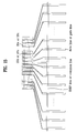
- FIG. 15 is a layout of an LCD device according to the seventh embodiment of the present invention.
- FIG. 4 is a layout of an LCD device according to the first embodiment of the present invention.
- interconnection lines 44 a in a center portion of an interconnection line part between a driving IC 41 and a gate line or a data line 42 are thickened, so that capacitance between an interconnection line 44 a in the center portion and a common electrode (not shown) of an upper substrate 45 is substantially the same as the capacitance of between an interconnection line 44 b in an outer portion of the interconnection line part.
- the interconnection line part generally includes an initial part connected to the driving IC; an end part connected to gate lines or data lines in a straight-line shape, and the rest middle part formed in a slanted or curved shape.
- an interconnection line is thickened resulting in a greater distance between a driving IC and TFT-LCD. Accordingly, in the present invention, the interconnection lines in a part of interconnection line adjacent the data or gate line and the end part of an interconnection line part are thickened, but a part of the initial part of the interconnection line is not thickened, thereby maintaining a distance between the driving IC and TFT-LCD module in itself.
- FIG. 5 is a layout of an LCD device according to the second embodiment of the present invention.
- supplementary metal patterns 54 are formed between interconnection lines 52 to be electrically connected to the interconnection lines 52 .
- the supplementary metal pattern 54 is formed of the same material as the interconnection line, or a gate line or a data line.
- supplementary metal patterns 54 connected to the interconnection line in a center portion of the interconnection line part can be larger size than supplementary metal patterns in outer portion of the interconnection line part.
- length of a supplementary metal pattern 54 in the center portion is relatively longer than supplementary metal patterns 54 in the outer portion while keeping a same width.
- FIG. 6 is a layout of an LCD device according to the third embodiment or the sixth embodiment of the present invention.
- a conductive layer B in a roughly triangle shape is formed so that a center portion of an interconnection line part A is wider than an outer portion, thereby forming a compensation capacitor between the conductive layer B and the respective interconnection lines.
- the center portion of a compensation capacitor formed between the interconnection lines and the conductive layer has larger capacity than the outer portion of a compensation capacitor formed between the interconnection lines and the conductive layer.
- the conductive layer B is connected to a voltage line, for example, a common voltage line C, for preventing static electricity.
- FIGS. 7A to 7C are sectional views of TFT of a cell array part of an LCD device according to the third embodiment of the present invention
- FIGS. 8A to 8C are sectional views of an LCD device according to the third embodiment of the present invention taken along line I–I′ of FIG. 6 .
- a compensation capacitor is formed in a data interconnecting ling part when a TFT of a cell array of an LCD device is formed as a top gate type polysilicon transistor.
- the compensation capacitor is formed using the conductive layer as a semiconductor layer doped with impurities.
- a buffer layer 31 is deposited on an entire surface of a glass substrate 30 .
- a semiconductor layer for example, polysilicon, is deposited over the buffer layer 31 and then is selectively removed, so that a first semiconductor layer 32 and a second semiconductor layer 33 are respectively formed in regions where TFTs of a cell array part will be formed and where interconnection lines will be formed. Then, a gate insulating film 34 is formed on the entire substrate 30 .
- a metal layer is deposited on the entire surface and then is selectively removed, so that a gate electrode 35 is formed on a gate insulating film 34 above the first semiconductor layer 32 .
- impurity ions are implanted on the entire surface of the first and second semiconductor layers at both sides of the gate electrode 35 , thereby forming impurity regions.
- an impurity region of the first semiconductor layer 32 at both sides of the gate electrode 35 becomes source and drain regions 32 a and 32 b , and an impurity region of the second semiconductor layer 33 is converted to a conductive layer.
- an interlayer insulating film 36 is formed on the entire surface of the substrate 30 . Then, the gate insulating 33 and the interlayer insulating film 36 are selectively removed, so that contact holes to the source and drain regions 32 a and 32 b of the first semiconductor layer 32 are formed.
- a metal layer is deposited on the entire surface and then selectively removed, so that data lines having source and drain electrodes and data interconnection lines are formed. That is, a source electrode 37 a of a data line 37 extends to and is electrically connected to a source region 32 a , and a drain electrode 37 b is connected to a drain region 32 b . Also, data interconnecting lines 37 c extend from the data line.
- a passivation film 38 is formed on the entire surface including the data line 37 and data interconnection lines 37 c including the source and drain electrodes 37 a and 37 b . Subsequently, a contact hole is formed to expose the drain electrode 37 b , and then a pixel electrode 39 is formed in the pixel region.
- compensation capacitors are formed between the data interconnection lines 37 c and the semiconductor layer 33 without an additional mask. Also, as shown in FIG. 6 , compensation capacitors between the respective interconnection lines and the semiconductor layer has a capacitor capacitance that is greater in a center portion of the interconnection line part than in an outer portion.
- a metal pattern of a roughly triangle shape is formed, so that data interconnection lines in a center portion are wider than in an outer portion, thereby forming compensation capacitors between the metal pattern and the respective interconnection lines.
- the conductive layer is formed of a semiconductor layer doped with impurities in the third embodiment of the present invention
- the conductive layer is formed of a gate metal layer in the fourth embodiment of the present invention.
- FIGS. 9A to 9C are sectional views of TFT of a cell array part of an LCD device according to the fourth embodiment of the present invention
- FIGS. 10A to 10C are sectional views of an LCD device according to the fourth embodiment of the present invention taken along line I–I′ of FIG. 6 .
- a compensation capacitor is formed of gate metal layer when the TFTs of a cell array of an LCD device are formed of top gate polysilicon transistors.
- a buffer layer 31 is deposited on an entire surface of a glass substrate 30 .
- a semiconductor layer for example, polysilicon, is deposited over the buffer layer 31 and then is selectively removed, so that a semiconductor layer 32 is formed in regions where TFTs of a cell array part will be formed. Then, a gate insulating film 34 is formed on the entire surface of the substrate 30 .
- a metal layer is deposited on the entire surface and selectively removed, so that a gate electrode 35 on a gate insulating film 34 above the first semiconductor layer 32 and a gate metal pattern layer 35 a are simultaneously formed in the interconnection line part. Then, impurity ions are implanted to the semiconductor layer 32 at both sides of the gate electrode 35 , so that impurity regions are formed. At this time, impurity region of the semiconductor layer 32 at both sides of the gate electrode 35 becomes source and drain regions 32 a and 32 b.
- an interlayer insulating film 36 is formed on the entire surface of the substrate 30 . Then, the gate insulating film 33 and the interlayer insulating film 36 are selectively removed, so that contact holes to the source and drain regions 32 a and 32 b of the semiconductor layer 32 are formed.
- a metal layer is then deposited and selectively removed, so that data lines and data interconnection lines including source and drain electrodes are formed. That is, a source electrode 37 a of a data line 37 extends to and is electrically connected to a source region 32 a , and a drain electrode 37 b is connected to a drain region 32 b . Also, data interconnection lines 37 c extend from the data line.
- a passivation film 38 is formed on the entire surface including the data line 37 and data interconnection lines 37 c including the source and drain electrodes 37 a and 37 b .
- a contact hole is formed to expose the drain electrode 37 b , and then a pixel electrode 39 is formed in the pixel region.
- compensation capacitors are formed between the data interconnection lines 37 c and the gate metal pattern layer 35 a without an additional mask. Also, as shown in FIG. 6 , compensation capacitors between the respective interconnection lines and the metal pattern layer have capacitance which is greater in a center portion rather than in an outer portion.
- a metal pattern layer of a roughly triangle shape is formed, so that data interconnection lines in a center portion of data interconnection line part are wider than those in an outer portion, thereby forming compensation capacitors between the metal pattern and the respective interconnection lines.
- FIGS. 11A and 11B are sectional views of TFT of a cell array part of an LCD device according to the fifth embodiment of the present invention
- FIGS. 12A and 12B are sectional views of an LCD device according to the fifth embodiment of the present invention taken along line I–I′ of FIG. 6 .
- a conductive layer is formed of a gate metal layer to form compensation capacitors when the TFTs of a cell array part of an LCD device are formed of amorphous silicon transistors.
- a metal layer is deposited on an entire surface of a glass substrate 30 and then selectively removed, so that a gate electrode 35 is formed in a cell array part and a gate metal patter layer 35 a is simultaneously formed in the interconnection line part. Then, an insulating film 34 is formed on the entire surface, and a semiconductor layer 32 is formed on the insulating film 34 above the gate electrode 35 .
- a metal layer is deposited and selectively removed, so that a data line 37 and data interconnection lines 37 c including source and drain electrodes 37 a and 37 b are formed. That is, a source electrode 37 a of a data line 37 extends from the data line 37 . A drain electrode 37 b is formed opposite the source electrode 37 a . Also, data interconnection lines 37 c extend from the data line 37 .
- a passivation film 38 is formed on the entire surface including the data line 37 and data interconnection lines 37 c including the source and drain electrodes 37 a and 37 b .
- a contact hole is formed to expose the drain electrode 37 b , and then a pixel electrode 39 is formed in the pixel region.
- compensation capacitors are formed between the data interconnection lines and the gate metal pattern layer 35 a without an additional mask. Also, as shown in FIG. 6 , compensation capacitors between the respective interconnection lines and the metal pattern layer have a capacitance that is greater in a center portion of the interconnection line part than in an outer portion.
- a conductive layer of a roughly triangle shape having a wider area in a center portion of an interconnection line part than in an outer portion of the interconnection line part is formed, thereby forming compensation capacitors between the conductive layer and the respective interconnection lines.
- the conductive layer is formed of a metal for forming the data line.
- FIGS. 13A to 13B are sectional views of TFI of a cell array part of an LCD device according to the sixth embodiment of the present invention
- FIGS. 14A and 14B are sectional views of an LCD device according to the sixth embodiment of the present invention taken along line I–I′ of FIG. 6 .
- compensation capacitors are formed of a data line metal layer when the TFTs of a cell array of an LCD device are a top gate type or a bottom gate type.
- TFTs of a cell array of an LCD device are a top gate type or a bottom gate type.
- a metal layer is deposited on an entire surface of a glass substrate 30 and then selectively removed, so that a gate electrode 35 is formed in a cell array part and a gate interconnection lines 35 b are formed in the interconnection line part. Then, an insulating film 34 is formed on the entire surface, and a semiconductor layer 32 is formed on the gate insulating film 34 above the gate electrode 35 .
- a metal layer is deposited on the entire surface and then selectively removed, so that a data line 37 and source and drain electrodes 37 a and 37 b are formed at both sides of the semiconductor layer 32 , and a data metal pattern 37 d is formed at the interconnection line part. That is, a source electrode 37 a of a data line 37 extends from the data line 37 and a drain electrode 37 b is formed opposite the source electrode 37 a . Also, the data metal pattern 37 d is overlapped with gate interconnection lines 35 b.
- a passivation film 38 is formed on the entire surface including the data line 37 and data interconnection lines 37 c including the source and drain electrodes 37 a and 37 b . Then, a contact hole is formed to expose the drain electrode 37 b , and then a pixel electrode 39 is formed in the pixel region.
- compensation capacitors are formed between the gate interconnection lines 35 b and the metal pattern layer 37 d without an additional mask. Also, as shown in FIG. 6 , compensation capacitors between the respective interconnection lines and the metal pattern layer have a capacitance that is greater in a center portion of the interconnection line part than an outer portion.
- an additional metal pattern is formed between the interconnection lines (gate interconnection lines or data interconnection lines).
- a supplementary metal pattern is formed between the interconnection lines.
- the supplementary metal pattern is formed of the same material as that of the respective interconnection lines and is electrically connected to the respective interconnection lines, thereby better compensating a capacitance.
- FIG. 15 is a layout of an LCD device according to the seventh embodiment of the present invention and is used herein to explain the present embodiment for use with gate interconnection lines 35 b and data interconnection lines 37 e.
- supplementary metal patterns (supplementary lines) 35 c or 37 e of the same materials as the gate interconnection lines 35 b and data interconnection lines 37 c are formed between gate interconnection lines 35 b or between data interconnection lines 37 c .
- the respective supplementary metal patterns 35 c or 37 e are electrically connected to adjacent interconnection lines 35 b or 37 c and formed with the same area.
- a conductive layer B of a roughly triangle shape has a larger area in a center portion of the interconnecting line part than in an outer portion of the interconnecting line part, so that a compensation capacitor is formed among the conductive layer B, the interconnection lines, and the supplementary metal patterns 35 c or 37 e .
- the conductive layer is formed with the same method explained in the third and sixth embodiments of the present invention.
- the compensation capacitor in a center portion of the interconnection line part between the interconnection lines, the supplementary metal patterns, and the conductive layer has greater capacitance than in an outer portion of the interconnection line part.
- voltage for preventing static electricity or a common voltage is applied to the conductive layer in each embodiment.
- An LCD device according to the present invention has the following advantages.
- an uneven picture image is generated by different capacitance of static electricity that results from different lengths of each interconnection line.
- the different capacitance of static electricity is overcome.
- the thickness of the interconnection lines is different for interconnection lines in different portions of the interconnecting line part, or supplementary metal patterns of the different sizes are additionally formed, or a separate conductive layer is formed in the interconnection line part to compensate the different capacitance of static electricity, thereby solving the problem of uneven picture image.
- a conductive layer corresponding to an interconnection line for forming the compensation capacitor is formed of active layer of TFTs or materials of gate electrode and data electrode, an additional mask is not required.
- the compensation capacitor is formed between each interconnection line and a conductive layer, in which a gate insulating film or an interlayer insulating film is formed, thereby obtaining a greater compensation capacitance.
Abstract
Description
Claims (5)
Priority Applications (1)
| Application Number | Priority Date | Filing Date | Title |
|---|---|---|---|
| US11/453,083 US7548225B2 (en) | 2000-12-21 | 2006-06-15 | Liquid crystal display device and method for fabricating the same |
Applications Claiming Priority (4)
| Application Number | Priority Date | Filing Date | Title |
|---|---|---|---|
| KR2000-79592 | 2000-12-21 | ||
| KR1020000079592A KR100606961B1 (en) | 2000-12-21 | 2000-12-21 | Thin Film Transistor - Liquid Crystal Display Module |
| KR10-2001-0074579A KR100447229B1 (en) | 2001-11-28 | 2001-11-28 | Liquid crystal display device and method for manufacturing the same |
| KR2001-74579 | 2001-11-28 |
Related Child Applications (1)
| Application Number | Title | Priority Date | Filing Date |
|---|---|---|---|
| US11/453,083 Division US7548225B2 (en) | 2000-12-21 | 2006-06-15 | Liquid crystal display device and method for fabricating the same |
Publications (2)
| Publication Number | Publication Date |
|---|---|
| US20020080317A1 US20020080317A1 (en) | 2002-06-27 |
| US7088323B2 true US7088323B2 (en) | 2006-08-08 |
Family
ID=26638654
Family Applications (2)
| Application Number | Title | Priority Date | Filing Date |
|---|---|---|---|
| US10/017,426 Expired - Lifetime US7088323B2 (en) | 2000-12-21 | 2001-12-18 | Liquid crystal display device and method for fabricating the same |
| US11/453,083 Expired - Lifetime US7548225B2 (en) | 2000-12-21 | 2006-06-15 | Liquid crystal display device and method for fabricating the same |
Family Applications After (1)
| Application Number | Title | Priority Date | Filing Date |
|---|---|---|---|
| US11/453,083 Expired - Lifetime US7548225B2 (en) | 2000-12-21 | 2006-06-15 | Liquid crystal display device and method for fabricating the same |
Country Status (3)
| Country | Link |
|---|---|
| US (2) | US7088323B2 (en) |
| JP (2) | JP4287609B2 (en) |
| CN (1) | CN1184607C (en) |
Cited By (5)
| Publication number | Priority date | Publication date | Assignee | Title |
|---|---|---|---|---|
| US20050117080A1 (en) * | 2000-12-23 | 2005-06-02 | Lee Joun H. | Liquid crystal display and manufacturing method of the same |
| US20060114216A1 (en) * | 2004-11-06 | 2006-06-01 | Shim Yeon-Tack | Gate line driver circuits for LCD displays |
| US20070034879A1 (en) * | 2005-08-12 | 2007-02-15 | Hyeong-Jun Park | Liquid crystal display |
| US20090262292A1 (en) * | 2008-04-16 | 2009-10-22 | Au Optronics Corporation | Electrical connectors between electronic devices |
| US9478181B2 (en) | 2013-07-15 | 2016-10-25 | Samsung Display Co., Ltd. | Display apparatus |
Families Citing this family (26)
| Publication number | Priority date | Publication date | Assignee | Title |
|---|---|---|---|---|
| US6897908B2 (en) * | 2001-11-23 | 2005-05-24 | Chi Mei Optoelectronics Corporation | Liquid crystal display panel having reduced flicker |
| TWI287132B (en) * | 2001-11-23 | 2007-09-21 | Chi Mei Optoelectronics Corp | A liquid crystal display having reduced flicker |
| KR100831235B1 (en) | 2002-06-07 | 2008-05-22 | 삼성전자주식회사 | A thin film transistor array panel |
| JP3854905B2 (en) * | 2002-07-30 | 2006-12-06 | 株式会社 日立ディスプレイズ | Liquid crystal display |
| JP3748075B2 (en) * | 2002-08-30 | 2006-02-22 | セイコーエプソン株式会社 | Electronic module, method for manufacturing the same, and electronic device |
| US6842200B1 (en) * | 2003-06-18 | 2005-01-11 | Hannstar Display Corporation | Liquid crystal panel having compensation capacitors for balancing RC delay effect |
| JP4674287B2 (en) * | 2003-12-12 | 2011-04-20 | 奇美電子股▲ふん▼有限公司 | Image display device |
| TWI232707B (en) * | 2004-03-31 | 2005-05-11 | Fujitsu Ltd | Display |
| JP3956959B2 (en) * | 2004-06-24 | 2007-08-08 | セイコーエプソン株式会社 | Organic EL device and electronic device |
| TWI276878B (en) | 2006-03-02 | 2007-03-21 | Au Optronics Corp | Display panel capable of reducing mismatching RC effect during signal transmission and method of manufacturing the same |
| JP5302101B2 (en) * | 2009-05-25 | 2013-10-02 | パナソニック液晶ディスプレイ株式会社 | Display device |
| JP5029670B2 (en) * | 2009-09-28 | 2012-09-19 | カシオ計算機株式会社 | Display device |
| TWM379077U (en) * | 2009-11-10 | 2010-04-21 | Chunghwa Picture Tubes Ltd | Active device array substrate |
| TWI408471B (en) * | 2009-11-23 | 2013-09-11 | Au Optronics Corp | Display device |
| JP4542202B2 (en) * | 2009-12-25 | 2010-09-08 | 三菱電機株式会社 | Display device |
| KR101773934B1 (en) * | 2010-10-21 | 2017-09-04 | 삼성디스플레이 주식회사 | Display panel and display apparatus having the same |
| CN102789755B (en) * | 2011-05-20 | 2016-04-27 | 群创光电股份有限公司 | Display panel |
| JP2013044891A (en) * | 2011-08-23 | 2013-03-04 | Sony Corp | Display device and electronic apparatus |
| KR20140035613A (en) * | 2012-09-14 | 2014-03-24 | 삼성전자주식회사 | Display panel and display apparatus comprising the same |
| EP3004979B1 (en) * | 2013-05-24 | 2019-01-16 | Raytheon Company | Adaptive-optics liquid-crystal array device having meander resistors |
| CN104730792B (en) * | 2015-04-08 | 2017-05-17 | 合肥京东方光电科技有限公司 | Array substrate and display device |
| KR20180024081A (en) | 2016-08-25 | 2018-03-08 | 엘지디스플레이 주식회사 | Display panel and display device |
| CN106526995B (en) * | 2016-10-31 | 2019-10-22 | 厦门天马微电子有限公司 | A kind of array substrate and display panel |
| TWI612364B (en) * | 2017-05-03 | 2018-01-21 | 友達光電股份有限公司 | Array Substrate |
| CN109920801B (en) * | 2019-03-11 | 2022-02-01 | 京东方科技集团股份有限公司 | Array substrate, manufacturing method thereof and display device |
| TWI812463B (en) * | 2022-09-13 | 2023-08-11 | 友達光電股份有限公司 | Stretchable pixel array substrate |
Citations (16)
| Publication number | Priority date | Publication date | Assignee | Title |
|---|---|---|---|---|
| JPH06202153A (en) | 1992-12-28 | 1994-07-22 | Fujitsu Ltd | Thin-film transistor matrix device and its production |
| JPH0876136A (en) | 1994-09-08 | 1996-03-22 | Hitachi Ltd | Liquid crystal display device |
| JPH08271927A (en) | 1995-03-30 | 1996-10-18 | Sanyo Electric Co Ltd | Display device and its production |
| US5574582A (en) | 1992-04-10 | 1996-11-12 | Matsushita Electric Industrial Co., Ltd | Active matrix liquid crystal display panel with scanning electrodes acting as capacitor electrode and black matrix |
| US5757450A (en) * | 1994-09-08 | 1998-05-26 | Hitachi, Ltd. | Liquid crystal display with color filters and sizes of inclined linear wiring and terminal electrodes adjusted for equal resistances |
| JPH1138445A (en) | 1997-07-18 | 1999-02-12 | Nec Corp | Production of thin-film transistor array substrate |
| JPH11190856A (en) | 1993-09-20 | 1999-07-13 | Hitachi Ltd | Liquid crystal display device |
| US6052171A (en) * | 1998-03-05 | 2000-04-18 | Sharp Kabushiki Kaisha | Liquid crystal display with electrically connected integrated circuits and opposite voltage line between input and output wirings |
| US6172732B1 (en) * | 1995-06-16 | 2001-01-09 | Hitachi, Ltd. | Liquid crystal display device suited to narrow frame |
| KR20010028531A (en) | 1999-09-21 | 2001-04-06 | 구본준, 론 위라하디락사 | Liquid Crystal Display Device |
| US6310666B1 (en) * | 1997-10-24 | 2001-10-30 | Lg. Philips Lcd Co., Ltd. | Manufacturing method of liquid crystal display preventing RF discharge damage |
| US20020030648A1 (en) * | 1998-05-19 | 2002-03-14 | Akira Yamamoto | Liquid crystal display device |
| US6465824B1 (en) * | 2000-03-09 | 2002-10-15 | General Electric Company | Imager structure |
| US6522378B1 (en) * | 1998-03-26 | 2003-02-18 | Matsushita Electric Industrial Co., Ltd. | Liquid crystal display and manufacture therefore |
| US6569717B1 (en) * | 1999-02-26 | 2003-05-27 | Seiko Epson Corporation | Semiconductor device production method, electro-optical device production method, semiconductor device, and electro-optical device |
| US6683669B1 (en) * | 1999-08-06 | 2004-01-27 | Sharp Kabushiki Kaisha | Apparatus and method for fabricating substrate of a liquid crystal display device and interconnects therein |
Family Cites Families (4)
| Publication number | Priority date | Publication date | Assignee | Title |
|---|---|---|---|---|
| JP3148461B2 (en) | 1993-05-26 | 2001-03-19 | 三洋電機株式会社 | Liquid crystal display module signal wiring structure |
| JP3298829B2 (en) | 1998-06-26 | 2002-07-08 | 株式会社小松製作所 | Self-propelled crushing machine |
| JP2000162628A (en) | 1998-11-26 | 2000-06-16 | Matsushita Electric Ind Co Ltd | Liquid crystal display element |
| JP3539555B2 (en) * | 1999-10-21 | 2004-07-07 | シャープ株式会社 | Liquid crystal display |
-
2001
- 2001-12-18 US US10/017,426 patent/US7088323B2/en not_active Expired - Lifetime
- 2001-12-21 CN CNB011403950A patent/CN1184607C/en not_active Expired - Lifetime
- 2001-12-21 JP JP2001389623A patent/JP4287609B2/en not_active Expired - Fee Related
-
2006
- 2006-06-15 US US11/453,083 patent/US7548225B2/en not_active Expired - Lifetime
-
2008
- 2008-06-11 JP JP2008152644A patent/JP2008209959A/en active Pending
Patent Citations (16)
| Publication number | Priority date | Publication date | Assignee | Title |
|---|---|---|---|---|
| US5574582A (en) | 1992-04-10 | 1996-11-12 | Matsushita Electric Industrial Co., Ltd | Active matrix liquid crystal display panel with scanning electrodes acting as capacitor electrode and black matrix |
| JPH06202153A (en) | 1992-12-28 | 1994-07-22 | Fujitsu Ltd | Thin-film transistor matrix device and its production |
| JPH11190856A (en) | 1993-09-20 | 1999-07-13 | Hitachi Ltd | Liquid crystal display device |
| JPH0876136A (en) | 1994-09-08 | 1996-03-22 | Hitachi Ltd | Liquid crystal display device |
| US5757450A (en) * | 1994-09-08 | 1998-05-26 | Hitachi, Ltd. | Liquid crystal display with color filters and sizes of inclined linear wiring and terminal electrodes adjusted for equal resistances |
| JPH08271927A (en) | 1995-03-30 | 1996-10-18 | Sanyo Electric Co Ltd | Display device and its production |
| US6172732B1 (en) * | 1995-06-16 | 2001-01-09 | Hitachi, Ltd. | Liquid crystal display device suited to narrow frame |
| JPH1138445A (en) | 1997-07-18 | 1999-02-12 | Nec Corp | Production of thin-film transistor array substrate |
| US6310666B1 (en) * | 1997-10-24 | 2001-10-30 | Lg. Philips Lcd Co., Ltd. | Manufacturing method of liquid crystal display preventing RF discharge damage |
| US6052171A (en) * | 1998-03-05 | 2000-04-18 | Sharp Kabushiki Kaisha | Liquid crystal display with electrically connected integrated circuits and opposite voltage line between input and output wirings |
| US6522378B1 (en) * | 1998-03-26 | 2003-02-18 | Matsushita Electric Industrial Co., Ltd. | Liquid crystal display and manufacture therefore |
| US20020030648A1 (en) * | 1998-05-19 | 2002-03-14 | Akira Yamamoto | Liquid crystal display device |
| US6569717B1 (en) * | 1999-02-26 | 2003-05-27 | Seiko Epson Corporation | Semiconductor device production method, electro-optical device production method, semiconductor device, and electro-optical device |
| US6683669B1 (en) * | 1999-08-06 | 2004-01-27 | Sharp Kabushiki Kaisha | Apparatus and method for fabricating substrate of a liquid crystal display device and interconnects therein |
| KR20010028531A (en) | 1999-09-21 | 2001-04-06 | 구본준, 론 위라하디락사 | Liquid Crystal Display Device |
| US6465824B1 (en) * | 2000-03-09 | 2002-10-15 | General Electric Company | Imager structure |
Cited By (7)
| Publication number | Priority date | Publication date | Assignee | Title |
|---|---|---|---|---|
| US20050117080A1 (en) * | 2000-12-23 | 2005-06-02 | Lee Joun H. | Liquid crystal display and manufacturing method of the same |
| US7348196B2 (en) * | 2000-12-23 | 2008-03-25 | Lg.Philips Lcd Co., Ltd. | Liquid crystal display and manufacturing method of the same |
| US20060114216A1 (en) * | 2004-11-06 | 2006-06-01 | Shim Yeon-Tack | Gate line driver circuits for LCD displays |
| US20070034879A1 (en) * | 2005-08-12 | 2007-02-15 | Hyeong-Jun Park | Liquid crystal display |
| US7522226B2 (en) * | 2005-08-12 | 2009-04-21 | Samsung Electronics Co., Ltd. | Liquid crystal display |
| US20090262292A1 (en) * | 2008-04-16 | 2009-10-22 | Au Optronics Corporation | Electrical connectors between electronic devices |
| US9478181B2 (en) | 2013-07-15 | 2016-10-25 | Samsung Display Co., Ltd. | Display apparatus |
Also Published As
| Publication number | Publication date |
|---|---|
| JP2008209959A (en) | 2008-09-11 |
| US20060232739A1 (en) | 2006-10-19 |
| JP4287609B2 (en) | 2009-07-01 |
| JP2002277893A (en) | 2002-09-25 |
| CN1360296A (en) | 2002-07-24 |
| CN1184607C (en) | 2005-01-12 |
| US20020080317A1 (en) | 2002-06-27 |
| US7548225B2 (en) | 2009-06-16 |
Similar Documents
| Publication | Publication Date | Title |
|---|---|---|
| US7548225B2 (en) | Liquid crystal display device and method for fabricating the same | |
| US7855767B2 (en) | Transflective liquid crystal display | |
| US7511793B2 (en) | Liquid crystal display having additional signal lines to define additional pixel regions | |
| KR100477130B1 (en) | Thin Film Transistor Board and Manufacturing Method of Flat Drive Liquid Crystal Display | |
| US7843545B2 (en) | Liquid crystal display comprising a first dummy pattern formed alternately and apart from a second dummy pattern and method of manufacturing the same | |
| US6862069B2 (en) | Liquid crystal display device and fabricating method thereof | |
| US6011309A (en) | Wiring structure of thin film transistor array and method of manufacturing the same | |
| US7768618B2 (en) | Liquid crystal display device and fabrication method thereof | |
| US20090209160A1 (en) | Chip on glass type liquid crystal display device and method for fabricating the same | |
| KR100475552B1 (en) | Liquid crystal display device and method for manufacturing the same | |
| JP2000171818A (en) | Liquid crystal display device | |
| US20060146246A1 (en) | Liquid crystal display and fabricating method thereof | |
| US20070164948A1 (en) | Liquid crystal display | |
| US6839120B2 (en) | Reflective or transflective liquid crystal display device and method for manufacturing the same | |
| US7710525B2 (en) | Thin film transistor, fabrication method thereof, liquid crystal display panel device having the same, and fabrication method thereof | |
| US20050253150A1 (en) | Active matrix substrate and method of manufacturing the same | |
| JP4109864B2 (en) | Matrix array substrate and manufacturing method thereof | |
| US6476895B1 (en) | Liquid crystal display | |
| KR100447229B1 (en) | Liquid crystal display device and method for manufacturing the same | |
| CN218995843U (en) | Array substrate, display panel and display device | |
| TWI803378B (en) | Driving circuit film and display device having the same | |
| KR20050066425A (en) | Liquid crystal display panel and method of fabricating the same | |
| KR100637058B1 (en) | Liquid Crystal Display | |
| KR100543026B1 (en) | Thin film transistor liquid crystal display | |
| KR20040098869A (en) | Pad structure of liquid crystal display |
Legal Events
| Date | Code | Title | Description |
|---|---|---|---|
| AS | Assignment |
Owner name: LG.PHILIPS LCD CO., LTD., KOREA, REPUBLIC OF Free format text: ASSIGNMENT OF ASSIGNORS INTEREST;ASSIGNORS:YEO, JU CHUN;JEONG, HOON;REEL/FRAME:012386/0257;SIGNING DATES FROM 20011217 TO 20011218 |
|
| AS | Assignment |
Owner name: LG.PHILIPS LCD CO., LTD., KOREA, REPUBLIC OF Free format text: ASSIGNMENT OF ASSIGNORS INTEREST;ASSIGNORS:YEO, JU CHUN;JEONG, HOON;REEL/FRAME:018002/0559;SIGNING DATES FROM 20011217 TO 20011218 |
|
| STCF | Information on status: patent grant |
Free format text: PATENTED CASE |
|
| AS | Assignment |
Owner name: LG DISPLAY CO., LTD., KOREA, REPUBLIC OF Free format text: CHANGE OF NAME;ASSIGNOR:LG.PHILIPS LCD CO., LTD.;REEL/FRAME:021754/0230 Effective date: 20080304 Owner name: LG DISPLAY CO., LTD.,KOREA, REPUBLIC OF Free format text: CHANGE OF NAME;ASSIGNOR:LG.PHILIPS LCD CO., LTD.;REEL/FRAME:021754/0230 Effective date: 20080304 |
|
| FEPP | Fee payment procedure |
Free format text: PAYER NUMBER DE-ASSIGNED (ORIGINAL EVENT CODE: RMPN); ENTITY STATUS OF PATENT OWNER: LARGE ENTITY Free format text: PAYOR NUMBER ASSIGNED (ORIGINAL EVENT CODE: ASPN); ENTITY STATUS OF PATENT OWNER: LARGE ENTITY |
|
| FPAY | Fee payment |
Year of fee payment: 4 |
|
| FPAY | Fee payment |
Year of fee payment: 8 |
|
| MAFP | Maintenance fee payment |
Free format text: PAYMENT OF MAINTENANCE FEE, 12TH YEAR, LARGE ENTITY (ORIGINAL EVENT CODE: M1553) Year of fee payment: 12 |