US7090343B2 - Printing-fluid container - Google Patents
Printing-fluid container Download PDFInfo
- Publication number
- US7090343B2 US7090343B2 US11/131,747 US13174705A US7090343B2 US 7090343 B2 US7090343 B2 US 7090343B2 US 13174705 A US13174705 A US 13174705A US 7090343 B2 US7090343 B2 US 7090343B2
- Authority
- US
- United States
- Prior art keywords
- printing
- ink
- fluid
- container
- reservoir
- Prior art date
- Legal status (The legal status is an assumption and is not a legal conclusion. Google has not performed a legal analysis and makes no representation as to the accuracy of the status listed.)
- Expired - Lifetime
Links
Images


Classifications
-
- B—PERFORMING OPERATIONS; TRANSPORTING
- B41—PRINTING; LINING MACHINES; TYPEWRITERS; STAMPS
- B41J—TYPEWRITERS; SELECTIVE PRINTING MECHANISMS, i.e. MECHANISMS PRINTING OTHERWISE THAN FROM A FORME; CORRECTION OF TYPOGRAPHICAL ERRORS
- B41J2/00—Typewriters or selective printing mechanisms characterised by the printing or marking process for which they are designed
- B41J2/005—Typewriters or selective printing mechanisms characterised by the printing or marking process for which they are designed characterised by bringing liquid or particles selectively into contact with a printing material
- B41J2/01—Ink jet
- B41J2/17—Ink jet characterised by ink handling
- B41J2/175—Ink supply systems ; Circuit parts therefor
- B41J2/17503—Ink cartridges
- B41J2/17543—Cartridge presence detection or type identification
- B41J2/17546—Cartridge presence detection or type identification electronically
-
- B—PERFORMING OPERATIONS; TRANSPORTING
- B41—PRINTING; LINING MACHINES; TYPEWRITERS; STAMPS
- B41J—TYPEWRITERS; SELECTIVE PRINTING MECHANISMS, i.e. MECHANISMS PRINTING OTHERWISE THAN FROM A FORME; CORRECTION OF TYPOGRAPHICAL ERRORS
- B41J2/00—Typewriters or selective printing mechanisms characterised by the printing or marking process for which they are designed
- B41J2/005—Typewriters or selective printing mechanisms characterised by the printing or marking process for which they are designed characterised by bringing liquid or particles selectively into contact with a printing material
- B41J2/01—Ink jet
- B41J2/17—Ink jet characterised by ink handling
- B41J2/175—Ink supply systems ; Circuit parts therefor
- B41J2/17503—Ink cartridges
- B41J2/17513—Inner structure
-
- B—PERFORMING OPERATIONS; TRANSPORTING
- B41—PRINTING; LINING MACHINES; TYPEWRITERS; STAMPS
- B41J—TYPEWRITERS; SELECTIVE PRINTING MECHANISMS, i.e. MECHANISMS PRINTING OTHERWISE THAN FROM A FORME; CORRECTION OF TYPOGRAPHICAL ERRORS
- B41J2/00—Typewriters or selective printing mechanisms characterised by the printing or marking process for which they are designed
- B41J2/005—Typewriters or selective printing mechanisms characterised by the printing or marking process for which they are designed characterised by bringing liquid or particles selectively into contact with a printing material
- B41J2/01—Ink jet
- B41J2/17—Ink jet characterised by ink handling
- B41J2/175—Ink supply systems ; Circuit parts therefor
- B41J2/17503—Ink cartridges
- B41J2/1752—Mounting within the printer
- B41J2/17523—Ink connection
-
- B—PERFORMING OPERATIONS; TRANSPORTING
- B41—PRINTING; LINING MACHINES; TYPEWRITERS; STAMPS
- B41J—TYPEWRITERS; SELECTIVE PRINTING MECHANISMS, i.e. MECHANISMS PRINTING OTHERWISE THAN FROM A FORME; CORRECTION OF TYPOGRAPHICAL ERRORS
- B41J2/00—Typewriters or selective printing mechanisms characterised by the printing or marking process for which they are designed
- B41J2/005—Typewriters or selective printing mechanisms characterised by the printing or marking process for which they are designed characterised by bringing liquid or particles selectively into contact with a printing material
- B41J2/01—Ink jet
- B41J2/17—Ink jet characterised by ink handling
- B41J2/175—Ink supply systems ; Circuit parts therefor
- B41J2/17503—Ink cartridges
- B41J2/17526—Electrical contacts to the cartridge
- B41J2/1753—Details of contacts on the cartridge, e.g. protection of contacts
-
- B—PERFORMING OPERATIONS; TRANSPORTING
- B41—PRINTING; LINING MACHINES; TYPEWRITERS; STAMPS
- B41J—TYPEWRITERS; SELECTIVE PRINTING MECHANISMS, i.e. MECHANISMS PRINTING OTHERWISE THAN FROM A FORME; CORRECTION OF TYPOGRAPHICAL ERRORS
- B41J2/00—Typewriters or selective printing mechanisms characterised by the printing or marking process for which they are designed
- B41J2/005—Typewriters or selective printing mechanisms characterised by the printing or marking process for which they are designed characterised by bringing liquid or particles selectively into contact with a printing material
- B41J2/01—Ink jet
- B41J2/17—Ink jet characterised by ink handling
- B41J2/175—Ink supply systems ; Circuit parts therefor
- B41J2/17503—Ink cartridges
- B41J2/17543—Cartridge presence detection or type identification
- B41J2/1755—Cartridge presence detection or type identification mechanically
-
- B—PERFORMING OPERATIONS; TRANSPORTING
- B41—PRINTING; LINING MACHINES; TYPEWRITERS; STAMPS
- B41J—TYPEWRITERS; SELECTIVE PRINTING MECHANISMS, i.e. MECHANISMS PRINTING OTHERWISE THAN FROM A FORME; CORRECTION OF TYPOGRAPHICAL ERRORS
- B41J2/00—Typewriters or selective printing mechanisms characterised by the printing or marking process for which they are designed
- B41J2/005—Typewriters or selective printing mechanisms characterised by the printing or marking process for which they are designed characterised by bringing liquid or particles selectively into contact with a printing material
- B41J2/01—Ink jet
- B41J2/17—Ink jet characterised by ink handling
- B41J2/175—Ink supply systems ; Circuit parts therefor
- B41J2/17503—Ink cartridges
- B41J2/17553—Outer structure
Landscapes
- Ink Jet (AREA)
- Pens And Brushes (AREA)
- Containers And Packaging Bodies Having A Special Means To Remove Contents (AREA)
- Packages (AREA)
- Inking, Control Or Cleaning Of Printing Machines (AREA)
- Supply Devices, Intensifiers, Converters, And Telemotors (AREA)
- Feedback Control In General (AREA)
- Glass Compositions (AREA)
- Steering Control In Accordance With Driving Conditions (AREA)
- Particle Formation And Scattering Control In Inkjet Printers (AREA)
- Printing Methods (AREA)
Abstract
A printing-fluid container includes a reservoir having an outer-face. A keying pocket is recessed from the outer-face of the reservoir and configured to mate with a complementary key post of a printing-fluid container bay.
Description
This is a continuation of application Ser. No. 10/632,408 filed on Jul. 31, 2003, now U.S. Pat. No. 7,004,564 which is hereby incorporated by reference.
Inkjet printing systems often utilize one or more replaceable ink containers that hold a finite volume of ink. An ink container can be replaced if the ink container is unable to deliver ink. For example, an ink container can be replaced if all of the ink in the ink container is used and the ink container is empty. Many known ink containers are unable to deliver all of the ink in the ink container and are considered to be effectively empty although some ink remains in the ink container. Such ink containers can be replaced when the ink container ceases to adequately deliver ink. Users generally prefer ink containers that do not have to be frequently replaced. Furthermore, users generally prefer ink containers that are relatively easy to replace when replacement is necessary.
Printing-fluid delivery system 16′ includes an off-axis ink-supply station 40. An “off-axis” ink-supply may be located apart from a printhead so that the printhead can scan across a printing zone while the ink-supply remains substantially stationary. Such an arrangement may decrease the total weight of a printhead assembly compared to a printhead assembly that includes an on-axis ink-supply. A relatively light printhead assembly may require relatively less energy to move, while moving faster, quieter, and/or with less vibration than a printhead with an integrated on-axis ink-supply. An off-axis ink-supply may be positioned for easy access to facilitate replenishing the ink-supply and may be sized to accommodate a desired volume of ink. As explained in more detail below, an ink-supply station may be configured for front loading so that a printing-fluid container can be laterally inserted into a printing system. The stationary position and relatively easy access of an off-axis ink-supply can allow for relatively large volumes of ink to be stored and delivered.
An off-axis ink-supply may include containers for storing and delivery one or more colors of ink as well as other printing-fluids. For example, ink-supply station 40 includes six ink-container bays configured to accommodate six corresponding ink containers. In the illustrated embodiment, ink-supply station 40 includes yellow bay 42, dark-magenta bay 44, light-magenta bay 46, dark-cyan bay 48, light-cyan bay 50, and black bay 52, which respectively are adapted to receive yellow ink container 54, dark-magenta ink container 56, light-magenta ink container 58, dark-cyan ink container 60, light-cyan ink container 62, and black ink container 64. Other printing systems may be designed for use with more or fewer colors, including colors different than those described above. It should be understood that as used herein, “ink” may be used in a general sense to refer to other printing fluids, such as preconditioners, fixers, etc., which may also held by an ink-container and delivered via a fluid delivery system. Two or more ink containers holding a printing fluid of the same color and/or type may be used in the same printing system. In some embodiments, one or more of the ink-container bays may be sized differently than another ink-container bay. For example, in the illustrated embodiment, black bay 52 is larger than the other ink-container bays, and therefore can accommodate a relatively larger ink container. As is described in more detail below, a particular ink-container bay may accommodate ink containers of differing sizes.
The ink transport system may include one or more mechanisms configured to effectuate the transport of ink through an ink transport path. Such a mechanism may work to establish a pressure differential that encourages the movement of ink. In the illustrated embodiment, fluid transport system 70 includes a pump 74 configured to effectuate the transport of ink through each tube 72. Such a pump may be configured as a bi-directional pump that is configured to move ink in different directions through a corresponding ink transport path.
An ink transport path may include two or more portions. For example, each tube 72 includes a static portion 76 linking an ink container to the pump and a dynamic portion 78 linking the pump to the printhead. The transport path may also include a pumping portion that effectively links the static portion to the dynamic portion and interacts with the pump to effectuate ink transport. The individual portions of an ink transport path may be physically distinct segments that are fluidically linked by one or more interconnects. In some embodiments, a single length of tube linking an ink container to the printhead may be functionally divided into two or more portions, including static and dynamic portions. In the illustrated embodiment, dynamic portion 78 is adapted to link a stationary ink-supply station to a scanning printhead that moves during printing, and therefore the dynamic portion is configured to move and flex with the printhead. The static portion, which links a stationary ink-supply station to a stationary pump, may remain substantially fixed.
An ink container of ink-supply station 40 may include a vent configured to facilitate the input and output of ink from the container. For example, a vent may fluidically couple the inside of an ink container to the atmosphere to help reduce unfavorable pressure gradients that may hinder ink transport. Such a vent may be configured to limit ink from exiting the ink container through the vent, thus preventing unnecessary ink dissipation. An exemplary vent in the form of a fluidic interface is described in more detail below.
Printing-fluid delivery system 16′ may include a vent chamber 90 configured to reduce ink evaporation and/or other ink loss. Each ink container of ink-supply station 40 may be fluidically coupled to vent chamber 90 via a tube 92 linking the vent of that ink container to the vent chamber. In other words, an ink-container vent may be connected to the vent chamber to facilitate ink transport between an ink container and the printhead. The vent chamber may decrease unfavorable pressure gradients while limiting evaporation of ink to the atmosphere. In some embodiments, vent chamber 90 may include a labyrinth that limits ink loss. Vent chamber 90 may be fixed in a substantially stationary position.
As mentioned above, FIG. 2 somewhat schematically depicts printing-fluid delivery system 16′. The precise arrangement of the constituent elements of the printing-fluid delivery system may be physically arranged according to a desired industrial design. Similarly, the individual elements may vary from the illustrated embodiments while remaining within the scope of this disclosure. Size, shape, access, and aesthetics are among factors that may be considered when designing a fluid ejection system that utilizes a printing-fluid delivery system according to the present disclosure. Though described and illustrated with reference to an off-axis ink supply, it should be understood that many of the principles herein described are applicable to on-axis ink supplies. The off-axis ink supply is provided as a nonlimiting example, and on-axis ink supplies are also within the scope of this disclosure.
An ink delivery system may include an ink-level monitor configured to track the amount of ink available for delivery. An ink-level monitor may be configured to individually monitor individual ink containers, groups of ink containers supplying the same color of ink, and/or the collective ink-supply of the system. The ink-level monitor may cooperate with a notification system to inform a user of the status of the ink level, thus enabling a user to assess ink levels and prepare for ink replenishment. Furthermore, as described in more detail below, an ink container may include a memory and an associated electrical interface, and information regarding the ink-level of an ink container may be stored on such a memory and conveyed via the electrical interface.
Ink-container lid 122 includes an outer-face 126 that faces away from the contents of an ink container. Outer-face 126 can be designed to be the “forward” facing portion of an ink container when the ink container is installed in a corresponding ink-container bay. Accordingly, the outer-face may be referred to as a leading surface of the ink container or as being aligned with a leading plane of the ink container. In some embodiments, a portion of a printing-fluid container other than a lid similar to ink-container lid 122 may be the leading surface of the printing-fluid container.
Ink-container lid 122 can be formed with an outer-face 126 that has a substantially planar profile. As described in more detail below, the outer-face may include one or more recesses adapted to provide mechanical alignment and/or keying. The outer-face may additionally or alternatively include holes that pass from the outside of an ink container to the inside of an ink container. Such holes may be used as fluidic interfaces for moving a printing fluid and/or air from inside the ink container to outside the ink container, and vice versa. An entry point of each recess, hole, and/or other interface may be arranged on the same leading surface. In some embodiments, the entry points to various interfaces of a printing-fluid container may be located on towers that are raised above another portion of the leading surface. Such an embodiment may not have a substantially planar profile, yet the entry point of various mechanical, fluidic, and/or electrical interfaces may be aligned on a common leading plane. In some embodiments, the entry point to each interface may be arranged within an acceptable distance on either side of a leading plane. For example, in some embodiments, any forward or backward variation of an interface's entry point relative to the entry point of another interface may be less than approximately 5 mm, while in most embodiments such variations may be less than approximately 2 mm, or even 1 mm. An ink-container lid that has an outer-face with a substantially planar profile may be referred to as a substantially planar ink-container lid, although such an ink-container lid can have a measurable thickness, an irregular inner-side, and/or one or more surface deviations on its outer-face.
Ink-container lid 122 can be constructed as a unitary structural piece 130, as opposed to a combination of two or more structural pieces. Such a piece may be molded, extruded, or otherwise formed from a material selected for strength, weight, workability, cost, compatibility with ink, and/or other considerations. For example, the lid may be injection molded from a suitable synthetic material. Construction from a unitary structural piece produces an ink-container lid in which an inner-side and an outer-face are opposite sides of the same piece of material.
An ink-container lid constructed from a unitary structural piece may be fit with complementary auxiliary components. For example, a gasket may be used to promote a fluid-tight seal between the ink-container lid and a reservoir body. A fluidic interface formed in a unitary structural piece may be fit with a seal configured to selectively seal ink within the ink container. The seal may take the form of a septum, a ball and septum assembly, or other mechanism. A memory device may be affixed to ink-container lid 122 and the ink-container lid may be equipped with an electrical interface for transferring data to and from the memory device. Such auxiliary components can be adapted to integrally cooperate with the unitary structural piece that defines the general size and shape of the ink-container lid.
A portion of an ink-container reservoir body can be configured with a standard size and shape while another portion is configured with a size and shape that varies between two or more configurations. For example, FIG. 8 shows reservoir bodies 124 a–124 c that respectively include shoulder portions 132 a–132 c, which are similarly configured with respect to one another. Such shoulder portions have a width that is substantially the same as a corresponding width of the ink-container lid. Reservoir bodies 124 a–124 c also respectively include rear portions 134 a–134 c, which are differently configured with respect to one another. Such rear portions have a width that is less than a corresponding width of the ink-container lid. The shoulder portions and the rear portions are joined by rim portions 136 a–136 c that include latching surfaces 138 a–138 c. Configuring a portion of a reservoir body, such as shoulder portions 132 a–132 c, with a standard size and shape improves compatibility between different ink containers, similar to the compatibility provided by a standard ink-container lid 122. For example, different ink containers that have similarly configured shoulder portions, but which may have rear portions of differing sizes, can be secured by the same latching member.
As mentioned above, an ink-container lid may include one or more interface features corresponding to complementary features of an ink-container bay adapted to receive the ink container. For example, as shown in FIG. 5 , ink-container lid 122 includes an interface package 150 comprising an alignment pocket 152, a keying pocket 154, a top fluidic interface in the form of an air-interface 156, a bottom fluidic interface in the form of an ink-interface 158, and an electrical interface 160. Interface package 150 is positioned interior an outer perimeter 128 of ink-container lid 122. In other words, the constituent features of interface package 150 are not positioned around a lateral edge of the ink-container lid, or elsewhere on the reservoir body.
As described in more detail below, interface package 150 is an exemplary collection of mechanical, fluidic, and electrical interfaces adapted to enable and/or enhance ink delivery from the ink container. Interface package 150 is provided as a nonlimiting example, and other arrangements may include additional and/or alternative features. Furthermore, the positioning of the various features may vary from the illustrated embodiment.
A fit between alignment member 176 and alignment pocket 152 can be sufficiently tight so that when the alignment pocket engages the alignment member, ink-container lid 122 is effectively restricted to a desired movement path. In this manner, alignment of the ink-container lid and a corresponding ink-container bay can be ensured. The fit can be established by physical contact between portions of alignment pocket 152 and alignment member 176. Such contact may be along entire surfaces of the alignment pocket and the alignment member, as shown in the drawings. In some embodiments, contact may occur along less than entire surface portions. In some embodiments, mating of an alignment member with the alignment pocket may be less tight, and the alignment pocket may merely be sized to accommodate a projecting alignment member without tightly engaging the alignment member.
Ink-container lid 122 may include a progressive alignment mechanism, in which alignment of the ink-container lid becomes more precise as the ink-container lid is more completely seated in an ink-container bay. For example, outer perimeter 128 may be sized slightly smaller than corresponding sidewalls 180 of ink-container bay 170, and the ink-container bay may be configured to engage the ink-container lid before the alignment pocket tightly engages the alignment member. Therefore, the outer-perimeter can provide a course alignment for the ink-container lid. The fit between the ink container and sidewalls 180 can be relatively tolerant so that it is easy to initiate the course alignment. Although the course alignment may be less precise than the alignment provided by alignment pocket 172, the ink container can be in a greater range of positions when the course alignment is initiated compared to when fine alignment is initiated. The ink container and ink-container bay may be configured so that alignment pocket 152 is directed to a position to engage alignment member 176 by the course alignment interaction between outer-perimeter 128, shoulder portion 132, and sidewalls 180. In some embodiments, course alignment may not include an actual physical interaction, but rather a visual cue for placing an ink container into a coarsely aligned position.
A progressive alignment system can be used to ensure that aspects of ink-container lid 122 are properly aligned with corresponding features of ink-container bay 170. In other words, the fit between the alignment pocket and the alignment member may be designed to achieve a desired level of tightness before an aspect of the interface package (e.g. ink-interface, air-interface, keying pocket, electrical interface, etc.) engages a corresponding aspect of an ink-container bay. Progressive alignment may also facilitate initiation of alignment because there is a greater tolerance in ink container positioning at the beginning of seating compared to when the ink container is fully seated into the ink-container bay. Once alignment is initiated, the ink container may be effectively directed into a desired location with a desired orientation with increasing precision. Interaction between aspects of the ink container with aspects of the ink-container bay can be designed to initiate when the desired level of precision has been achieved. The progressive alignment system described above is provided as a nonlimiting example. Other progressive alignment systems may be used. Furthermore, some embodiments may utilize nonprogressive alignment systems.
A keying pocket can be used to provide physical validation that a fluid container is being inserted into the proper fluid-container bay. For example, a keying pocket may provide tactile feedback during an attempt to load an ink container into an ink-container bay. The keying pocket and/or key post may be configured so that the tactile feedback may be distinctly different depending on whether the ink container is being loaded in a bay set up to deliver the color of ink that the ink container is holding or a different color of ink. A keying pocket can be adapted to prohibit ink containers from being loaded into ink-container bays that do not include a key post corresponding to the keying pocket of the ink-container lid. In some embodiments, such an ink container may be loaded, however the interaction between the non complementary key post and keying pocket can generate a feel that is distinctly different than the feel of complementary keying features engaging one another. For example, there may be more resistance when inserting an ink container that includes a keying pocket that is not complementarily configured relative to the key post engaging the keying pocket.
Keying pocket 154 is shaped to mate with key post 190, so that each spoke effectively slides into a corresponding slot of the keying pocket. Unique keying interfaces may be based on the same general shape of a particular key post and keying pocket combination, but by rotating the orientation of the combination. For example, a different interface may be configured by rotating a symmetry angle of a key post that has the same general shape as key post 190. A corresponding keying pocket could be similarly rotated to produce a unique interface combination. For example, a symmetry angle can be rotated in 45° increments to yield 8 unique key post configurations. FIG. 13 shows five such configurations that may be used to key five colors of ink different than the color of ink keyed by key post 190. The above described key post and keying pocket configurations are provided as a nonlimiting example. Other keying interfaces may be used.
A keying interface may additionally and/or alternatively be varied relative to another keying interface by moving the relative position of the keying interface on an ink container and an associated ink-container bay. For example, using the example described above, in which a key post can be rotated in 45° increments to yield 8 different possible key post configurations; a location of the key post may be selected between 3 different locations to yield a total of 24 (8×3) unique key post configurations. Keying pockets with corresponding locations and orientations may be configured to mate with such key posts. If desired, additional keying configurations may be achieved by decreasing the magnitude of rotation increments, adding key post locations, adding new key post shapes, etc. For example, a key post can be rotated in 22.5° increments to yield 16 different configurations. Similarly, different key post and key pocket shapes can be used, examples of which include “T,” “L,” and “V” shapes.
As described above, a keying feature and/or alignment feature of an ink container may be configured as a recess that extends into the ink container as opposed to a protuberance that extends outward from the ink container. Such a recess provides a robust interface that is resistant to damage. Furthermore, configuring an ink container with a recess does not disrupt the generally planar profile of the outer-face of an ink-container lid.
In the illustrated embodiment, the fluidic interfaces are configured as septa having a ball seal design. The fluidic interfaces are adapted to seal the contents of the ink container so that the contents do not undesirably leak. Each interface is configured to releasably receive a fluid connector, such as a hollow needle, that can penetrate the selective seal of a septum and transfer fluid into and out of the ink container. The septum can be configured to prevent undesired leaking when a fluid connector is inserted and after a fluid connector has been removed. For example, the septum may closely engulf an inserted needle, so that ink or air can pass through the needle, but not between the needle and the septum.
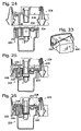
As shown in FIGS. 14–16 , ink-interface 158 can be positioned near a gravitational bottom of an ink container that is orientated in a seated position in a corresponding ink-container bay. In such a position, fluid connector 202 is also near a gravitational bottom of the ink container. Furthermore, an ink-container reservoir body 124 can be shaped with a bottom surface 204 that slopes towards the fluid connector so that ink can naturally flow to the fluid connector. In other words, bottom surface 204 is gravitationally biased toward a low portion of the ink container. In the illustrated embodiment, the shape of the ink container produces an ink well 206 configured to allow ink to drain into position for access by fluid connector 202. By virtue of the position of the ink well relative to the remainder of the reservoir, printing fluid may accumulate in the ink well as the level of ink lowers. Fluid connector 202 can continue to draw ink occupying ink well 206 as the ink level lowers during use.
The well, ink-interface, and corresponding fluid connector may be positioned to limit the amount of ink that is stranded in the ink container, thereby minimizing waste. In some embodiments, a printing fluid container may deliver all but at most 2 cubic centimeters of printing fluid, with all but at most 1 cubic centimeter being delivered in most embodiments. As mentioned above, the size of the reservoir body may be increased, thus providing an increased ink capacity. However, such reservoirs may be configured with an ink well similar to ink well 206, or otherwise be configured so that an ink-interface is near the bottom of the reservoir, thus minimizing the amount of ink that can be stranded within the ink container. In other words, according to this disclosure, the amount of ink that may be stranded inside of an ink container does not have to be proportional to the ink capacity of the ink container.
As shown in FIG. 5 , outer-face 126 of ink-container lid 122 may include a protrusion 210 at which ink-interface 158 is located. In the illustrated embodiment, protrusion 210 is configured to allow a center portion of ink-interface 158, through which a fluid connector may pass, to be positioned near a low point of the ink-container reservoir. Therefore, a fluid connector may be inserted into the fluidic interface to draw ink from a relatively low area of the ink container, thus facilitating the extraction of a greater percentage of ink from the ink container. Protrusion 210 also allows the ink-interface to be located near the bottom of the ink reservoir while remaining interior outer perimeter 128 of outer-face 126.
In FIG. 21 , a fluid level 214 is schematically illustrated and shows how much ink may be drawn from the printing-fluid container when the container includes a well. In contrast, FIG. 22 schematically illustrates a fluid level 216 of a container that does not include a well. As can be appreciated by comparison, well 206 limits the amount of stranded printing fluid. While the depth of fluid level 214 and fluid level 216 may be comparable, the volume of printing fluid associated with fluid level 214 is considerably less than the volume of printing fluid associated with fluid level 216. Well 206 may be configured so that the cross-sectional area of the portion of a fluid container that bounds fluid level 214 is less than the cross-sectional area of the portion of a fluid container that bounds fluid level 216, thus decreasing the respective volumes assuming similar depths. In some embodiments, well 206 may be configured to reduce the top surface area (and corresponding volume) of a fluid level that corresponds to an effectively empty fluid container by at least 75%, and usually by 90% or more. Furthermore, as mentioned above, the capacity of the remainder of an ink container may be increased without changing the size of the well and without generating an increase in the amount of printing fluid that will be stranded in the container. Well 206 may be variously sized and shaped. As a general rule, the volume of well 206 may be decreased to lessen the amount of printing fluid that may be stranded within the container. Well 206 may be sized to accommodate a fluid interface with enough additional volume to allow the free flow of printing fluid into the well.
Air-interface 156 may be positioned gravitationally above ink-interface 158 when an ink container is orientated in a seated position in a corresponding ink-container bay. Top fluidic interface 156 may function as a venting port configured to facilitate pressure equalization in the ink container. When ink is drawn from ink-interface 158, air-interface 156 may allow air to enter the ink-container reservoir to equalize the pressure therein. Similarly, if ink is returned to the ink container, the air-interface may vent air out of the ink container. As mentioned above, the top fluidic interface may be fluidically coupled to a vent chamber 90 configured to reduce ink evaporation and/or other ink loss. As described and illustrated herein, an ink container (and a corresponding ink-container bay or other mechanism for seating an ink container) may be configured for lateral installation. A configuration which facilitates lateral installation also provides design flexibility in a printing system. In particular, a lateral installation allows a printing system to be designed for front, back, or side loading of an ink container, as opposed to being restricted to top loading.
As illustrated in FIG. 2 , an ink-interface may be an active interface, which is fluidically coupled to a pump 74 that is configured to control the delivery of ink to and from the ink container. An air-interface may be a passive interface, which is not directly controlled by a pump, but rather is configured to allow a pressure balance to be naturally achieved. It should be understood that the illustrated embodiment is provided as a nonlimiting example, and that other configurations are within the scope of this disclosure. For example, in some embodiments, an air-interface may be an active interface that is actively controlled to produce a desired pressure within the ink container.
Positioning the alignment pocket near the center of the outer-face allows each of the other interfaces to be located relatively near the alignment pocket. Positioning alignment pocket 152 proximate the other interfaces may facilitate aligning those interfaces with corresponding features of an ink-container bay. For example, positioning the interfaces proximate the alignment pocket may decrease the effect of any tolerance that exists in the alignment interface. Therefore, if the alignment interface permits some variation in the alignment, the other interfaces may remain within an acceptable position for engaging corresponding portions of an ink-container bay. In other words, the effects of any movement allowed by the alignment interface may be amplified in proportion to the relative distance from the alignment pocket. Therefore, such effects may be minimized by positioning the various interface features proximate the alignment pocket.
As illustrated in FIG. 5 , fluidic interfaces of an ink container may be located along a vertical axis V of the front surface of the printing-fluid container. Alignment pocket 152 may also be located along vertical axis V, so that vertical axis V intersects top fluidic interface 156, bottom fluidic interface 158, and alignment pocket 152. Similarly, electrical interface 160 and/or keying pocket 154 may be located along a horizontal axis H of the front surface of the printing-fluid container. Alignment pocket 152 may also be located along horizontal axis H, so that horizontal axis H intersects the electrical interface, the keying pocket, and the alignment pocket. In other words, the alignment package may be arranged in a “cross” configuration with the alignment pocket located at the center of the cross (the intersection of vertical axis V and horizontal axis H). In some embodiments, horizontal axis H may bisect the segment of vertical axis V between top fluidic interface 156 and bottom fluidic interface 158 and/or vertical axis V may bisect the segment of horizontal axis H between electrical interface 160 and keying pocket 154. Furthermore, as shown in FIG. 5 , vertical axis V may be an axis of symmetry, wherein the basic shape of the fluid-container is the same to the left and right of the axis. As used with relation to an axis and an interface feature, the term “intersect” means that at least a portion of the interface feature is crossed by the axis. Therefore, a common axis may intersect two or more features, although the precise centers of such features are not aligned on the axis.
A pair of latch slots located on opposite sides of an ink container may be positioned coplanar with an alignment pocket. For example, latch slots 222 may be positioned on the same plane as alignment pocket 230. In the illustrated embodiment, the latching surfaces and alignment pocket are each intersected by a common horizontally extending plane. Keying pocket 232 and electrical interface 234 may also be positioned on the same plane. It should be understood that other latching mechanisms may be configured to apply latching pressure along a plane that passes through an alignment pocket. In some embodiments, a latch slot may be positioned on another plane that intersects an alignment pocket, such as on a vertical plane that intersects an alignment pocket and one or more fluidic interfaces.
The above described side-latch and inner-latch mechanisms are provided as nonlimiting examples of possible latching configurations. A side-latch mechanism and an inner-latch mechanism may be used cooperatively or independently of one another. Similarly, a side-latch mechanism and/or an inner-latch mechanism may additionally or alternatively be used with respect to other latching mechanisms, such as the latching mechanism described with reference to FIGS. 3 and 4 . Other suitable latching mechanisms may also be used.
As described above with reference to the illustrated embodiments, an ink container may include an interface package with one or more fluidic, mechanical, and/or electrical interfaces. The ink container may be described as having a leading surface, which is configured to be laterally inserted into an ink-container bay of an ink supply station. The leading surface of an ink container may be configured as a substantially planar outer-surface. Each of the respective interfaces of the interface package may be located on the substantially planar leading surface of the ink container. The leading surface may be described as having an outer perimeter, and the respective interfaces of the interface package may be located interior the outer perimeter. The illustrated embodiments show a nonlimiting example of a configuration for arranging an interface package. It should be understood that other arrangements are within the scope of this disclosure.
Although the present disclosure has been provided with reference to the foregoing operational principles and embodiments, it will be apparent to those skilled in the art that various changes in form and detail may be made without departing from the spirit and scope defined in the appended claims. The present disclosure is intended to embrace all such alternatives, modifications and variances. Where the disclosure or claims recite “a,” “a first,” or “another” element, or the equivalent thereof, they should be interpreted to include one or more such elements, neither requiring nor excluding two or more such elements.
Claims (22)
1. A printing-fluid container, comprising:
a reservoir defining a bounded volume configured to contain printing fluid, the reservoir including a front face having an outer perimeter; and
a keying pocket recessed from the front face and extending into the bounded volume of the reservoir, the keying pocket being configured to mate with a complementary key post of a printing-fluid container bay.
2. The printing-fluid container of claim 1 , wherein the reservoir holds a printing fluid designated by a characteristic of the keying pocket.
3. The printing-fluid container of claim 2 , wherein the characteristic includes an orientation of the keying pocket.
4. The printing-fluid container of claim 3 , wherein the orientation of the keying pocket is one of a plurality of different orientations, each designating a different printing fluid.
5. The printing-fluid container of claim 4 , wherein each different orientation designates a different printing-fluid color.
6. The printing-fluid container of claim 2 , wherein the keying pocket prevents the printing-fluid container from being seated in any printing-fluid container bay adapted to extract a printing fluid other than the printing fluid held within the reservoir.
7. The printing-fluid container of claim 1 , wherein the front face of the reservoir is substantially planar.
8. The printing-fluid container of claim 1 , wherein the keying pocket recesses substantially normal to the front faced.
9. The printing-fluid container of claim 1 , wherein the front face is a leading surface adapted to be laterally installed into the printing-fluid container bay.
10. The printing-fluid container of claim 9 , wherein the leading surface includes a fluidic interface.
11. A printing-fluid container, comprising:
a reservoir defining a bounded volume configured to contain printing fluid, the reservoir including a front face having an outer perimeter; and
a keying pocket recessed from the front face and extending into the bounded volume of the reservoir, the keying pocket being configured to mate with a complementary key post of a printing-fluid container bay, wherein the reservoir holds a printing fluid designated by a shape of the keying pocket.
12. The printing-fluid container of claim 11 , wherein the shape of the keying pocket is one of a plurality of different shapes, each designating a different printing fluid.
13. The printing-fluid container of claim 12 , wherein each different shape designates a different printing-fluid color.
14. A printing-fluid container, comprising:
a reservoir defining a bounded volume configured to contain printing fluid, the reservoir including a front face having an outer perimeter; and
a keying pocket recessed from the front face and extending into the bounded volume of the reservoir, the keying pocket being configured to mate with a complementary key post of a printing-fluid container bay, wherein the front face of the reservoir is substantially upright.
15. A printing-fluid container, comprising:
a reservoir defining a bounded volume configured to hold a printing fluid the reservoir including a leading surface; and
a keying pocket extending into the bounded volume of the reservoir, wherein the keying pocket is configured to prevent the reservoir from being seated in a printing-fluid container bay adapted to extract a printing fluid other than the printing fluid held within the reservoir.
16. The printing-fluid container of claim 15 , wherein an orientation of the keying pocket of the printing-fluid container designates the printing fluid held within the reservoir.
17. The printing-fluid container of claim 16 , wherein the orientation of the keying pocket designates a printing-fluid color of the printing fluid held within the reservoir.
18. The printing-fluid container of claim 15 , wherein the keying pocket is configured to mate with an outwardly extending key post of a printing-fluid container bay adapted to extract the printing fluid held within the reservoir.
19. The printing fluid container of claim 15 , wherein the keying pocket recesses substantially normal the leading surface.
20. The printing fluid container of claim 15 , wherein the leading surface is substantially planar.
21. The printing fluid container of claim 15 , wherein a fluidic interface is located on the leading surface.
22. A printing-fluid container, comprising:
reservoir means defining a cavity for holding a printing fluid, the reservoir means including a leading surface; and
keying means recessed from the leading surface and extending into the cavity of the reservoir means for restrictively mating to key posts associated with printing-fluid container bays adapted to receive the printing fluid held in the reservoir means.
Priority Applications (3)
| Application Number | Priority Date | Filing Date | Title |
|---|---|---|---|
| US11/131,747 US7090343B2 (en) | 2003-07-31 | 2005-05-17 | Printing-fluid container |
| US11/458,470 US7506973B2 (en) | 2003-07-31 | 2006-07-19 | Printing-fluid container |
| US12/366,646 US7963644B2 (en) | 2003-07-31 | 2009-02-06 | Printing-fluid container |
Applications Claiming Priority (2)
| Application Number | Priority Date | Filing Date | Title |
|---|---|---|---|
| US10/632,408 US7004564B2 (en) | 2003-07-31 | 2003-07-31 | Printing-fluid container |
| US11/131,747 US7090343B2 (en) | 2003-07-31 | 2005-05-17 | Printing-fluid container |
Related Parent Applications (1)
| Application Number | Title | Priority Date | Filing Date |
|---|---|---|---|
| US10/632,408 Continuation US7004564B2 (en) | 2003-07-31 | 2003-07-31 | Printing-fluid container |
Related Child Applications (1)
| Application Number | Title | Priority Date | Filing Date |
|---|---|---|---|
| US11/458,470 Continuation US7506973B2 (en) | 2003-07-31 | 2006-07-19 | Printing-fluid container |
Publications (2)
| Publication Number | Publication Date |
|---|---|
| US20050212881A1 US20050212881A1 (en) | 2005-09-29 |
| US7090343B2 true US7090343B2 (en) | 2006-08-15 |
Family
ID=34104367
Family Applications (4)
| Application Number | Title | Priority Date | Filing Date |
|---|---|---|---|
| US10/632,408 Expired - Lifetime US7004564B2 (en) | 2003-07-31 | 2003-07-31 | Printing-fluid container |
| US11/131,747 Expired - Lifetime US7090343B2 (en) | 2003-07-31 | 2005-05-17 | Printing-fluid container |
| US11/458,470 Expired - Fee Related US7506973B2 (en) | 2003-07-31 | 2006-07-19 | Printing-fluid container |
| US12/366,646 Expired - Fee Related US7963644B2 (en) | 2003-07-31 | 2009-02-06 | Printing-fluid container |
Family Applications Before (1)
| Application Number | Title | Priority Date | Filing Date |
|---|---|---|---|
| US10/632,408 Expired - Lifetime US7004564B2 (en) | 2003-07-31 | 2003-07-31 | Printing-fluid container |
Family Applications After (2)
| Application Number | Title | Priority Date | Filing Date |
|---|---|---|---|
| US11/458,470 Expired - Fee Related US7506973B2 (en) | 2003-07-31 | 2006-07-19 | Printing-fluid container |
| US12/366,646 Expired - Fee Related US7963644B2 (en) | 2003-07-31 | 2009-02-06 | Printing-fluid container |
Country Status (13)
| Country | Link |
|---|---|
| US (4) | US7004564B2 (en) |
| EP (6) | EP1839880B1 (en) |
| JP (1) | JP2007500619A (en) |
| CN (1) | CN100448676C (en) |
| AT (3) | ATE466731T1 (en) |
| BR (1) | BRPI0412611B1 (en) |
| DE (2) | DE602004026943D1 (en) |
| DK (2) | DK2258554T3 (en) |
| ES (4) | ES2345161T3 (en) |
| HU (2) | HUE039668T2 (en) |
| PL (4) | PL2258554T3 (en) |
| PT (2) | PT2258554E (en) |
| WO (1) | WO2005016651A1 (en) |
Cited By (5)
| Publication number | Priority date | Publication date | Assignee | Title |
|---|---|---|---|---|
| US20070013753A1 (en) * | 2003-07-31 | 2007-01-18 | Charlie Steinmetz | Printing-fluid container |
| US20080165232A1 (en) * | 2007-01-10 | 2008-07-10 | Kenneth Yuen | Ink cartridge |
| US20090141097A1 (en) * | 2007-11-29 | 2009-06-04 | Hirotake Nakamura | Ink supply device |
| US9738080B1 (en) | 2010-10-22 | 2017-08-22 | Hewlett-Packard Development Company, L.P. | Fluid cartridge |
| US11067920B2 (en) | 2018-08-30 | 2021-07-20 | Hewlett-Packard Development Company, L.P. | Asymmetric key features |
Families Citing this family (23)
| Publication number | Priority date | Publication date | Assignee | Title |
|---|---|---|---|---|
| JP4492144B2 (en) * | 2003-12-08 | 2010-06-30 | ブラザー工業株式会社 | Inkjet recording device |
| JP4715115B2 (en) * | 2004-06-23 | 2011-07-06 | ブラザー工業株式会社 | Ink filling method |
| JP4561853B2 (en) * | 2008-03-27 | 2010-10-13 | ブラザー工業株式会社 | Droplet ejection device and liquid cartridge |
| TW201000323A (en) * | 2008-06-17 | 2010-01-01 | Qisda Corp | Ink storage module capable of controlling flow of ink and related printing system |
| US8727516B2 (en) | 2010-10-22 | 2014-05-20 | Hewlett-Packard Development Company, L.P. | Fluid cartridge |
| CN104118216B (en) * | 2010-10-22 | 2016-08-24 | 惠普发展公司,有限责任合伙企业 | Fluid box |
| CA2813381C (en) * | 2010-10-22 | 2014-12-16 | Hewlett Packard Development Company, L.P. | Fluid cartridge |
| AU2015201259B2 (en) * | 2010-10-22 | 2017-03-23 | Hewlett-Packard Development Company, L.P. | Fluid cartridge |
| US8651642B2 (en) | 2010-10-22 | 2014-02-18 | Hewlett-Packard Development Company, L.P. | Fluid cartridge |
| CN105538914B (en) * | 2010-10-22 | 2017-12-26 | 惠普发展公司,有限责任合伙企业 | Fluid box |
| ES2664893T3 (en) * | 2010-12-22 | 2018-04-23 | Seiko Epson Corporation | Cartridge |
| US8591014B2 (en) * | 2011-02-12 | 2013-11-26 | Hewlett-Packard Development Company, L.P. | Fluidic interface |
| USD875828S1 (en) | 2011-09-23 | 2020-02-18 | Hewlett-Packard Development Company, L.P. | Ink cartridge |
| US8857956B2 (en) | 2011-12-06 | 2014-10-14 | Brother Kogyo Kabushiki Kaisha | Cartridges and recording apparatuses |
| WO2018147869A1 (en) * | 2017-02-10 | 2018-08-16 | Hewlett-Packard Development Company, L.P. | Mechanical locking mechanism for fluid ejection |
| CN111741924A (en) * | 2018-05-21 | 2020-10-02 | 惠普发展公司,有限责任合伙企业 | Printing substance donor container |
| WO2020013848A1 (en) | 2018-07-13 | 2020-01-16 | Hewlett-Packard Development Company, L.P. | Print liquid supply interconnect in hose-fed housing |
| JP7000595B2 (en) | 2018-07-13 | 2022-01-19 | ヒューレット-パッカード デベロップメント カンパニー エル.ピー. | Printing liquid supply |
| AU2018431744B2 (en) | 2018-07-13 | 2021-12-23 | Hewlett-Packard Development Company, L.P. | Print liquid supply |
| KR102447095B1 (en) | 2018-07-13 | 2022-09-23 | 휴렛-팩커드 디벨롭먼트 컴퍼니, 엘.피. | printing liquid supply |
| US11420444B2 (en) | 2018-07-13 | 2022-08-23 | Hewlett-Packard Development Company, L.P. | Print liquid supply |
| USD934341S1 (en) | 2018-12-03 | 2021-10-26 | Hewlett-Packard Development Company, L.P. | Ink cartridge |
| EP4108464B1 (en) | 2018-12-03 | 2023-10-04 | Hewlett-Packard Development Company, L.P. | Printable liquid supply cartridges |
Citations (64)
| Publication number | Priority date | Publication date | Assignee | Title |
|---|---|---|---|---|
| US4053902A (en) | 1975-12-22 | 1977-10-11 | Siemens Aktiengesellschaft | Fluid pump for a writing device |
| DE3247875A1 (en) | 1981-12-28 | 1983-08-11 | Pitney Bowes, Inc., 06926 Stamford, Conn. | Ink supply system for an ink jet printer |
| US4419678A (en) | 1979-10-17 | 1983-12-06 | Canon Kabushiki Kaisha | Ink jet recording apparatus |
| US4551734A (en) | 1984-12-06 | 1985-11-05 | Tektronix, Inc. | Ink cartridge with ink level sensor |
| US4700202A (en) | 1983-02-23 | 1987-10-13 | Sharp Kabushiki Kaisha | Ink cartridge in an ink jet system printer |
| US4907019A (en) * | 1989-03-27 | 1990-03-06 | Tektronix, Inc. | Ink jet cartridges and ink cartridge mounting system |
| US4967207A (en) | 1989-07-26 | 1990-10-30 | Hewlett-Packard Company | Ink jet printer with self-regulating refilling system |
| JPH0316738A (en) | 1989-06-15 | 1991-01-24 | Nec Corp | Ink tank in ink jet printer |
| JPH04187448A (en) | 1990-11-21 | 1992-07-06 | Seiko Epson Corp | Ink cartridge |
| US5146243A (en) | 1991-07-29 | 1992-09-08 | Hewlett-Packard Company | Diaphragm cap system for ink-jet printers |
| EP0562717A1 (en) | 1992-02-24 | 1993-09-29 | Canon Kabushiki Kaisha | Valve mechanism for a liquid container in a liquid recording apparatus |
| US5293913A (en) * | 1991-07-12 | 1994-03-15 | Minnesota Mining And Manufacturing Company | Bottle keying system |
| WO1994007699A1 (en) | 1992-09-26 | 1994-04-14 | Willett International Limited | Air vent system with solvent vapour filter for an ink reservoir |
| EP0597628A1 (en) | 1992-11-10 | 1994-05-18 | SCITEX DIGITAL PRINTING, Inc. | Ink replenishment system for a continuous ink jet printer |
| EP0639462A2 (en) | 1993-08-19 | 1995-02-22 | Canon Kabushiki Kaisha | Ink tank cartridge and ink-jet apparatus in which the ink tank cartridge is installed |
| US5486855A (en) | 1990-12-27 | 1996-01-23 | Xerox Corporation | Apparatus for supplying ink to an ink jet printer |
| DE19540472A1 (en) | 1994-10-31 | 1996-05-02 | Hewlett Packard Co | Ink storage pen for ink jet printing head, ink supply and pen set up processes |
| US5523780A (en) | 1992-06-24 | 1996-06-04 | Canon Kabushiki Kaisha | Ink jet recording apparatus and ink cartridge mountable on said apparatus |
| US5541631A (en) | 1990-09-22 | 1996-07-30 | Canon Kabushiki Kaisha | Ink cartridge including projection for preventing erroneous loading |
| US5600358A (en) | 1993-06-30 | 1997-02-04 | Hewlett-Packard Company | Ink pen having a hydrophobic barrier for controlling ink leakage |
| US5682189A (en) | 1993-03-09 | 1997-10-28 | Fuji Xerox Co., Ltd. | Ink supply device for an ink jet recording apparatus |
| EP0803365A2 (en) | 1996-04-26 | 1997-10-29 | Pelikan Produktions Ag | An ink cartridge for a printer |
| EP0803364A2 (en) | 1996-04-25 | 1997-10-29 | Canon Kabushiki Kaisha | Ink refilling method for ink jet cartridge, recording apparatus using the method and ink container |
| US5734401A (en) | 1995-04-27 | 1998-03-31 | Hewlett-Packard Company | Fluid interconnect for coupling a replaceable ink supply with an ink-jet printer |
| US5745138A (en) | 1996-05-16 | 1998-04-28 | Ostermeier; Bruce H. | Ink chamber with pressure relief chamber having pressure relief aperture and microparticles to exert capilliary action on ink |
| US5751319A (en) | 1995-08-31 | 1998-05-12 | Colossal Graphics Incorporated | Bulk ink delivery system and method |
| US5757390A (en) | 1992-08-12 | 1998-05-26 | Hewlett-Packard Company | Ink volume sensing and replenishing system |
| US5784087A (en) | 1995-04-27 | 1998-07-21 | Owens-Illinois Closure Inc. | Liquid containment and dispensing device |
| US5854646A (en) | 1995-04-27 | 1998-12-29 | Hewlett-Packard Company | Diaphragm pump for ink supply |
| US5920333A (en) * | 1992-03-18 | 1999-07-06 | Willett International Limited | Replenishment of reservoirs |
| US5956054A (en) | 1990-02-02 | 1999-09-21 | Canon Kabushiki Kaisha | Ink jet recording apparatus including a recording head with inclined ejection outlets |
| US6048055A (en) | 1997-09-03 | 2000-04-11 | Fuji Photo Film Co., Ltd. | Ink tank system for ink jet printer |
| US6070976A (en) | 1996-04-05 | 2000-06-06 | Fuji Xerox Co., Ltd. | Ink tank and recording apparatus |
| US6086193A (en) | 1996-08-02 | 2000-07-11 | Seiko Epson Corporation | Ink cartridge and a printing device using the ink cartridge |
| US6102535A (en) | 1998-08-14 | 2000-08-15 | J.S. Staedtler Gmbh & Co. | Ink cartridge with closing device |
| US6183077B1 (en) * | 1995-04-27 | 2001-02-06 | Hewlett-Packard Company | Method and apparatus for keying ink supply containers |
| US6231173B1 (en) | 1994-10-31 | 2001-05-15 | Hewlett-Packard Company | Contact pad and fluid interconnect configuration on a print cartridge |
| US6243115B1 (en) | 2000-03-09 | 2001-06-05 | Lexmark International, Inc. | Pressurized ink supply and delivery system for an ink jet printer |
| US6264314B1 (en) * | 1991-05-27 | 2001-07-24 | Seiko Epson Corporation | Ink cartridge for ink jet recording apparatus |
| US6273562B1 (en) | 2000-03-29 | 2001-08-14 | Hewlett-Packard Company | Ink jet printer pen vent facility |
| US6276788B1 (en) | 1998-12-28 | 2001-08-21 | Xerox Corporation | Ink cartridge for an ink jet printer having quick disconnect valve 09 |
| US20010017641A1 (en) | 2000-01-21 | 2001-08-30 | Atsushi Kobayashi | Ink-jet recording apparatus |
| US6283586B1 (en) | 1998-03-04 | 2001-09-04 | Hewlett-Packard Company | Method and apparatus for refilling ink containers in a manner that preserves printhead life |
| US20010019347A1 (en) | 1999-01-28 | 2001-09-06 | Mark Hauck | Method for regulating pressure |
| US6286921B1 (en) | 1993-04-06 | 2001-09-11 | Sharp Kabushiki Kaisha | Ink cartridge of an ink jet printer and an ink jet printer including an ink cartridge |
| US6286944B1 (en) | 1993-05-21 | 2001-09-11 | Canon Kabushiki Kaisha | Ink jet unit with cartridge having controlled ink flow |
| US6286945B1 (en) | 1992-07-24 | 2001-09-11 | Canon Kabushiki Kaisha | Ink jet cartridge, ink jet head and printer |
| US20010020970A1 (en) | 2000-02-03 | 2001-09-13 | Akira Kuribayashi | Ink-transport system, ink-replacement method, ink-jet printing apparatus, and ink-supply system |
| US6293662B1 (en) | 1998-01-19 | 2001-09-25 | Canon Kabushiki Kaisha | Ink tank coupling method, ink jet recording apparatus, and ink tank |
| US6322205B1 (en) | 1997-01-21 | 2001-11-27 | Hewlett-Packard Company | Ink delivery system adapter |
| US6322207B1 (en) | 1995-04-27 | 2001-11-27 | Hewlett-Packard Company | Replaceable pump module for receiving replaceable ink supplies to provide ink to an ink jet printing system |
| US6350024B2 (en) | 1998-01-23 | 2002-02-26 | Hewlett-Packard Company | Diaphragm pump having an integral pressure plate |
| US20020080216A1 (en) | 2000-12-22 | 2002-06-27 | Dowell Daniel D. | Apparatus for providing ink to an ink jet print head |
| US20020101487A1 (en) | 2001-01-26 | 2002-08-01 | Petersen Daniel W. | Manifold for providing fluid connections between carriage-mounted ink containers and printheads |
| US20020118260A1 (en) | 2001-02-23 | 2002-08-29 | Waggoner Karen Wytmans | Inkjet printing system |
| US6443567B1 (en) | 1999-04-27 | 2002-09-03 | Canon Kabushiki Kaisha | Liquid ejecting cartridge and recording device using same |
| US6471333B1 (en) * | 2001-04-30 | 2002-10-29 | Hewlett-Packard Company | Method and apparatus for keying ink supply containers |
| US6494568B2 (en) | 2000-10-20 | 2002-12-17 | International United Technology Co., Ltd. | Ink cartridge with a pressure adjusting device |
| US20030020789A1 (en) | 2001-07-24 | 2003-01-30 | Nanodynamics Inc. | Ink cartridge with negative-pressure regulating mechanism |
| US6582068B2 (en) | 2000-01-21 | 2003-06-24 | Seiko Epson Corporation | Ink cartridge, and ink-jet recording apparatus using the same |
| US6585362B2 (en) | 2001-10-05 | 2003-07-01 | Eastman Kodak Company | Ink composition, ink cartridge having ink composition, and method of filling ink cartridge |
| US6648460B2 (en) | 2002-01-30 | 2003-11-18 | Hewlett-Packard Development Company, L.P. | High volumetric efficiency ink container vessel |
| US6666542B2 (en) | 2001-03-30 | 2003-12-23 | Brother Kogyo Kabushiki Kaisha | Ink cartridge for printer or the like and ink cartridge positioning and locking mechanism |
| US6719415B1 (en) * | 1999-04-27 | 2004-04-13 | Canon Kabushiki Kaisha | Ink container, valve unit, ink container manufacturing method, ink jet head cartridge and recording apparatus |
Family Cites Families (25)
| Publication number | Priority date | Publication date | Assignee | Title |
|---|---|---|---|---|
| US118260A (en) * | 1871-08-22 | Improvement in bearing-plates for railway rails | ||
| US20970A (en) * | 1858-07-20 | Improved electro-magnetic house-alarm | ||
| US80216A (en) * | 1868-07-21 | Improvement in spinning-machines | ||
| US104187A (en) * | 1870-06-14 | Feed-water-heating apparatus | ||
| US36680A (en) * | 1862-10-14 | Improvement in lamps | ||
| US17641A (en) * | 1857-06-23 | Improvement in boring-mills | ||
| US53902A (en) * | 1866-04-10 | Propeller-wheel | ||
| US19347A (en) * | 1858-02-16 | Island | ||
| US4272019A (en) * | 1978-10-17 | 1981-06-09 | Halaby Jr Samuel A | Fluid sprayer apparatus and method |
| US4611899A (en) * | 1983-01-08 | 1986-09-16 | Canon Kabushiki Kaisha | Developing apparatus |
| CH657629A5 (en) | 1983-08-25 | 1986-09-15 | Alusuisse | ELECTROLYSIS PAN. |
| JPH0825279B2 (en) * | 1986-06-25 | 1996-03-13 | キヤノン株式会社 | Ink supply device |
| US4853708A (en) * | 1988-03-03 | 1989-08-01 | Eastman Kodak Company | Ink cartridge and housing construction for multicolor ink jet printing apparatus |
| EP1234675B1 (en) * | 1989-08-05 | 2007-05-09 | Canon Kabushiki Kaisha | Ink jet recording apparatus and ink cartridge for the apparatus |
| US5777646A (en) * | 1995-12-04 | 1998-07-07 | Hewlett-Packard Company | Self-sealing fluid inerconnect with double sealing septum |
| US5530531A (en) * | 1995-03-15 | 1996-06-25 | Hewlett-Packard Company | Multiple cartridge keying apparatus |
| US6130695A (en) * | 1995-04-27 | 2000-10-10 | Hewlett-Packard Company | Ink delivery system adapter |
| JP3879788B2 (en) | 1997-08-11 | 2007-02-14 | セイコーエプソン株式会社 | Ink jet recording apparatus and ink cartridge used therefor |
| JP3888808B2 (en) | 1999-08-16 | 2007-03-07 | 富士通株式会社 | NAND nonvolatile memory |
| JP3687517B2 (en) | 2000-10-12 | 2005-08-24 | セイコーエプソン株式会社 | Ink cartridge connection structure and ink jet recording apparatus using the same |
| CA2371040A1 (en) * | 2001-02-09 | 2002-08-09 | Nobuyuki Hatasa | Liquid container and recording apparatus |
| US7147310B2 (en) * | 2002-01-30 | 2006-12-12 | Hewlett-Packard Development Company, L.P. | Printing-fluid container |
| US7104630B2 (en) * | 2003-07-31 | 2006-09-12 | Hewlett-Packard Development Company, L.P. | Printing-fluid container |
| US7004564B2 (en) * | 2003-07-31 | 2006-02-28 | Hewlett-Packard Development Company, L.P. | Printing-fluid container |
| US6959985B2 (en) * | 2003-07-31 | 2005-11-01 | Hewlett-Packard Development Company, L.P. | Printing-fluid container |
-
2003
- 2003-07-31 US US10/632,408 patent/US7004564B2/en not_active Expired - Lifetime
-
2004
- 2004-07-27 HU HUE15156761A patent/HUE039668T2/en unknown
- 2004-07-27 ES ES07107768T patent/ES2345161T3/en active Active
- 2004-07-27 WO PCT/US2004/024221 patent/WO2005016651A1/en not_active Application Discontinuation
- 2004-07-27 ES ES08162840T patent/ES2345740T3/en active Active
- 2004-07-27 PT PT101828168T patent/PT2258554E/en unknown
- 2004-07-27 JP JP2006522009A patent/JP2007500619A/en active Pending
- 2004-07-27 PT PT15156761T patent/PT2902207T/en unknown
- 2004-07-27 AT AT08162840T patent/ATE466731T1/en not_active IP Right Cessation
- 2004-07-27 DE DE602004026943T patent/DE602004026943D1/en active Active
- 2004-07-27 EP EP07107768A patent/EP1839880B1/en not_active Not-in-force
- 2004-07-27 DK DK10182816.8T patent/DK2258554T3/en active
- 2004-07-27 DE DE602004027097T patent/DE602004027097D1/en active Active
- 2004-07-27 EP EP10182816.8A patent/EP2258554B1/en active Active
- 2004-07-27 PL PL10182816T patent/PL2258554T3/en unknown
- 2004-07-27 DK DK15156761.7T patent/DK2902207T6/en active
- 2004-07-27 BR BRPI0412611-4A patent/BRPI0412611B1/en not_active IP Right Cessation
- 2004-07-27 ES ES15156761T patent/ES2686978T7/en active Active
- 2004-07-27 EP EP04779319A patent/EP1651443A1/en not_active Withdrawn
- 2004-07-27 HU HUE10182816A patent/HUE025189T2/en unknown
- 2004-07-27 PL PL08162840T patent/PL2028013T3/en unknown
- 2004-07-27 PL PL15156761T patent/PL2902207T6/en unknown
- 2004-07-27 PL PL07107768T patent/PL1839880T3/en unknown
- 2004-07-27 AT AT07107768T patent/ATE465882T1/en not_active IP Right Cessation
- 2004-07-27 CN CNB2004800285956A patent/CN100448676C/en not_active Expired - Fee Related
- 2004-07-27 EP EP15156761.7A patent/EP2902207B3/en active Active
- 2004-07-27 EP EP08162840A patent/EP2028013B1/en not_active Not-in-force
- 2004-07-27 EP EP10150804A patent/EP2168772B1/en not_active Not-in-force
- 2004-07-27 AT AT10150804T patent/ATE556852T1/en active
- 2004-07-27 ES ES10182816.8T patent/ES2536287T3/en active Active
-
2005
- 2005-05-17 US US11/131,747 patent/US7090343B2/en not_active Expired - Lifetime
-
2006
- 2006-07-19 US US11/458,470 patent/US7506973B2/en not_active Expired - Fee Related
-
2009
- 2009-02-06 US US12/366,646 patent/US7963644B2/en not_active Expired - Fee Related
Patent Citations (65)
| Publication number | Priority date | Publication date | Assignee | Title |
|---|---|---|---|---|
| US4053902A (en) | 1975-12-22 | 1977-10-11 | Siemens Aktiengesellschaft | Fluid pump for a writing device |
| US4419678A (en) | 1979-10-17 | 1983-12-06 | Canon Kabushiki Kaisha | Ink jet recording apparatus |
| DE3247875A1 (en) | 1981-12-28 | 1983-08-11 | Pitney Bowes, Inc., 06926 Stamford, Conn. | Ink supply system for an ink jet printer |
| US4700202A (en) | 1983-02-23 | 1987-10-13 | Sharp Kabushiki Kaisha | Ink cartridge in an ink jet system printer |
| US4551734A (en) | 1984-12-06 | 1985-11-05 | Tektronix, Inc. | Ink cartridge with ink level sensor |
| US4907019A (en) * | 1989-03-27 | 1990-03-06 | Tektronix, Inc. | Ink jet cartridges and ink cartridge mounting system |
| JPH0316738A (en) | 1989-06-15 | 1991-01-24 | Nec Corp | Ink tank in ink jet printer |
| US4967207A (en) | 1989-07-26 | 1990-10-30 | Hewlett-Packard Company | Ink jet printer with self-regulating refilling system |
| US5956054A (en) | 1990-02-02 | 1999-09-21 | Canon Kabushiki Kaisha | Ink jet recording apparatus including a recording head with inclined ejection outlets |
| US5541631A (en) | 1990-09-22 | 1996-07-30 | Canon Kabushiki Kaisha | Ink cartridge including projection for preventing erroneous loading |
| JPH04187448A (en) | 1990-11-21 | 1992-07-06 | Seiko Epson Corp | Ink cartridge |
| US5486855A (en) | 1990-12-27 | 1996-01-23 | Xerox Corporation | Apparatus for supplying ink to an ink jet printer |
| US6264314B1 (en) * | 1991-05-27 | 2001-07-24 | Seiko Epson Corporation | Ink cartridge for ink jet recording apparatus |
| US5293913A (en) * | 1991-07-12 | 1994-03-15 | Minnesota Mining And Manufacturing Company | Bottle keying system |
| US5146243A (en) | 1991-07-29 | 1992-09-08 | Hewlett-Packard Company | Diaphragm cap system for ink-jet printers |
| EP0562717A1 (en) | 1992-02-24 | 1993-09-29 | Canon Kabushiki Kaisha | Valve mechanism for a liquid container in a liquid recording apparatus |
| US5920333A (en) * | 1992-03-18 | 1999-07-06 | Willett International Limited | Replenishment of reservoirs |
| US5523780A (en) | 1992-06-24 | 1996-06-04 | Canon Kabushiki Kaisha | Ink jet recording apparatus and ink cartridge mountable on said apparatus |
| US6286945B1 (en) | 1992-07-24 | 2001-09-11 | Canon Kabushiki Kaisha | Ink jet cartridge, ink jet head and printer |
| US5757390A (en) | 1992-08-12 | 1998-05-26 | Hewlett-Packard Company | Ink volume sensing and replenishing system |
| WO1994007699A1 (en) | 1992-09-26 | 1994-04-14 | Willett International Limited | Air vent system with solvent vapour filter for an ink reservoir |
| EP0597628A1 (en) | 1992-11-10 | 1994-05-18 | SCITEX DIGITAL PRINTING, Inc. | Ink replenishment system for a continuous ink jet printer |
| US5682189A (en) | 1993-03-09 | 1997-10-28 | Fuji Xerox Co., Ltd. | Ink supply device for an ink jet recording apparatus |
| US6286921B1 (en) | 1993-04-06 | 2001-09-11 | Sharp Kabushiki Kaisha | Ink cartridge of an ink jet printer and an ink jet printer including an ink cartridge |
| US6286944B1 (en) | 1993-05-21 | 2001-09-11 | Canon Kabushiki Kaisha | Ink jet unit with cartridge having controlled ink flow |
| US5600358A (en) | 1993-06-30 | 1997-02-04 | Hewlett-Packard Company | Ink pen having a hydrophobic barrier for controlling ink leakage |
| EP0639462A2 (en) | 1993-08-19 | 1995-02-22 | Canon Kabushiki Kaisha | Ink tank cartridge and ink-jet apparatus in which the ink tank cartridge is installed |
| DE19540472A1 (en) | 1994-10-31 | 1996-05-02 | Hewlett Packard Co | Ink storage pen for ink jet printing head, ink supply and pen set up processes |
| US6231173B1 (en) | 1994-10-31 | 2001-05-15 | Hewlett-Packard Company | Contact pad and fluid interconnect configuration on a print cartridge |
| US6322207B1 (en) | 1995-04-27 | 2001-11-27 | Hewlett-Packard Company | Replaceable pump module for receiving replaceable ink supplies to provide ink to an ink jet printing system |
| US5854646A (en) | 1995-04-27 | 1998-12-29 | Hewlett-Packard Company | Diaphragm pump for ink supply |
| US20020036680A1 (en) | 1995-04-27 | 2002-03-28 | Hall Ronald W. | Method and apparatus for providing ink to an ink jet printing system |
| US5784087A (en) | 1995-04-27 | 1998-07-21 | Owens-Illinois Closure Inc. | Liquid containment and dispensing device |
| US6183077B1 (en) * | 1995-04-27 | 2001-02-06 | Hewlett-Packard Company | Method and apparatus for keying ink supply containers |
| US5734401A (en) | 1995-04-27 | 1998-03-31 | Hewlett-Packard Company | Fluid interconnect for coupling a replaceable ink supply with an ink-jet printer |
| US5751319A (en) | 1995-08-31 | 1998-05-12 | Colossal Graphics Incorporated | Bulk ink delivery system and method |
| US6070976A (en) | 1996-04-05 | 2000-06-06 | Fuji Xerox Co., Ltd. | Ink tank and recording apparatus |
| EP0803364A2 (en) | 1996-04-25 | 1997-10-29 | Canon Kabushiki Kaisha | Ink refilling method for ink jet cartridge, recording apparatus using the method and ink container |
| EP0803365A2 (en) | 1996-04-26 | 1997-10-29 | Pelikan Produktions Ag | An ink cartridge for a printer |
| US5745138A (en) | 1996-05-16 | 1998-04-28 | Ostermeier; Bruce H. | Ink chamber with pressure relief chamber having pressure relief aperture and microparticles to exert capilliary action on ink |
| US6086193A (en) | 1996-08-02 | 2000-07-11 | Seiko Epson Corporation | Ink cartridge and a printing device using the ink cartridge |
| US6322205B1 (en) | 1997-01-21 | 2001-11-27 | Hewlett-Packard Company | Ink delivery system adapter |
| US6048055A (en) | 1997-09-03 | 2000-04-11 | Fuji Photo Film Co., Ltd. | Ink tank system for ink jet printer |
| US6293662B1 (en) | 1998-01-19 | 2001-09-25 | Canon Kabushiki Kaisha | Ink tank coupling method, ink jet recording apparatus, and ink tank |
| US6350024B2 (en) | 1998-01-23 | 2002-02-26 | Hewlett-Packard Company | Diaphragm pump having an integral pressure plate |
| US6283586B1 (en) | 1998-03-04 | 2001-09-04 | Hewlett-Packard Company | Method and apparatus for refilling ink containers in a manner that preserves printhead life |
| US6102535A (en) | 1998-08-14 | 2000-08-15 | J.S. Staedtler Gmbh & Co. | Ink cartridge with closing device |
| US6276788B1 (en) | 1998-12-28 | 2001-08-21 | Xerox Corporation | Ink cartridge for an ink jet printer having quick disconnect valve 09 |
| US20010019347A1 (en) | 1999-01-28 | 2001-09-06 | Mark Hauck | Method for regulating pressure |
| US6443567B1 (en) | 1999-04-27 | 2002-09-03 | Canon Kabushiki Kaisha | Liquid ejecting cartridge and recording device using same |
| US6719415B1 (en) * | 1999-04-27 | 2004-04-13 | Canon Kabushiki Kaisha | Ink container, valve unit, ink container manufacturing method, ink jet head cartridge and recording apparatus |
| US20010017641A1 (en) | 2000-01-21 | 2001-08-30 | Atsushi Kobayashi | Ink-jet recording apparatus |
| US6582068B2 (en) | 2000-01-21 | 2003-06-24 | Seiko Epson Corporation | Ink cartridge, and ink-jet recording apparatus using the same |
| US20010020970A1 (en) | 2000-02-03 | 2001-09-13 | Akira Kuribayashi | Ink-transport system, ink-replacement method, ink-jet printing apparatus, and ink-supply system |
| US6243115B1 (en) | 2000-03-09 | 2001-06-05 | Lexmark International, Inc. | Pressurized ink supply and delivery system for an ink jet printer |
| US6273562B1 (en) | 2000-03-29 | 2001-08-14 | Hewlett-Packard Company | Ink jet printer pen vent facility |
| US6494568B2 (en) | 2000-10-20 | 2002-12-17 | International United Technology Co., Ltd. | Ink cartridge with a pressure adjusting device |
| US20020080216A1 (en) | 2000-12-22 | 2002-06-27 | Dowell Daniel D. | Apparatus for providing ink to an ink jet print head |
| US20020101487A1 (en) | 2001-01-26 | 2002-08-01 | Petersen Daniel W. | Manifold for providing fluid connections between carriage-mounted ink containers and printheads |
| US20020118260A1 (en) | 2001-02-23 | 2002-08-29 | Waggoner Karen Wytmans | Inkjet printing system |
| US6666542B2 (en) | 2001-03-30 | 2003-12-23 | Brother Kogyo Kabushiki Kaisha | Ink cartridge for printer or the like and ink cartridge positioning and locking mechanism |
| US6471333B1 (en) * | 2001-04-30 | 2002-10-29 | Hewlett-Packard Company | Method and apparatus for keying ink supply containers |
| US20030020789A1 (en) | 2001-07-24 | 2003-01-30 | Nanodynamics Inc. | Ink cartridge with negative-pressure regulating mechanism |
| US6585362B2 (en) | 2001-10-05 | 2003-07-01 | Eastman Kodak Company | Ink composition, ink cartridge having ink composition, and method of filling ink cartridge |
| US6648460B2 (en) | 2002-01-30 | 2003-11-18 | Hewlett-Packard Development Company, L.P. | High volumetric efficiency ink container vessel |
Cited By (10)
| Publication number | Priority date | Publication date | Assignee | Title |
|---|---|---|---|---|
| US20070013753A1 (en) * | 2003-07-31 | 2007-01-18 | Charlie Steinmetz | Printing-fluid container |
| US7506973B2 (en) * | 2003-07-31 | 2009-03-24 | Hewlett-Packard Development Company, L.P. | Printing-fluid container |
| US20080165232A1 (en) * | 2007-01-10 | 2008-07-10 | Kenneth Yuen | Ink cartridge |
| US20090141097A1 (en) * | 2007-11-29 | 2009-06-04 | Hirotake Nakamura | Ink supply device |
| US8162457B2 (en) | 2007-11-29 | 2012-04-24 | Brother Kogyo Kabushiki Kaisha | Ink supply device |
| US9738080B1 (en) | 2010-10-22 | 2017-08-22 | Hewlett-Packard Development Company, L.P. | Fluid cartridge |
| US9770914B2 (en) | 2010-10-22 | 2017-09-26 | Hewlett-Packard Development Company, L.P. | Fluid cartridge |
| US10112400B2 (en) | 2010-10-22 | 2018-10-30 | Hewlett-Packard Development Company, L.P. | Fluid cartridge |
| US10391775B2 (en) | 2010-10-22 | 2019-08-27 | Hewlett-Packard Development Company, L.P. | Fluid cartridge |
| US11067920B2 (en) | 2018-08-30 | 2021-07-20 | Hewlett-Packard Development Company, L.P. | Asymmetric key features |
Also Published As
Similar Documents
| Publication | Publication Date | Title |
|---|---|---|
| US7090343B2 (en) | Printing-fluid container | |
| US6962408B2 (en) | Printing-fluid container | |
| US6959985B2 (en) | Printing-fluid container | |
| US8075117B2 (en) | Printing fluid container | |
| US8070274B2 (en) | Printing-fluid container | |
| US7104630B2 (en) | Printing-fluid container |
Legal Events
| Date | Code | Title | Description |
|---|---|---|---|
| AS | Assignment |
Owner name: HEWLETT-PACKARD DEVELOPMENT COMPANY, L.P., TEXAS Free format text: ASSIGNMENT OF ASSIGNORS INTEREST;ASSIGNORS:STEINMETZ, CHARLIE;GONZALES, CURT;PETERSEN, DANIEL W.;AND OTHERS;REEL/FRAME:016582/0688;SIGNING DATES FROM 20050506 TO 20050510 |
|
| STCF | Information on status: patent grant |
Free format text: PATENTED CASE |
|
| CC | Certificate of correction | ||
| FPAY | Fee payment |
Year of fee payment: 4 |
|
| FPAY | Fee payment |
Year of fee payment: 8 |
|
| FPAY | Fee payment |
Year of fee payment: 12 |