US7090527B2 - Transceiver delatching mechanism - Google Patents
Transceiver delatching mechanism Download PDFInfo
- Publication number
- US7090527B2 US7090527B2 US11/251,720 US25172005A US7090527B2 US 7090527 B2 US7090527 B2 US 7090527B2 US 25172005 A US25172005 A US 25172005A US 7090527 B2 US7090527 B2 US 7090527B2
- Authority
- US
- United States
- Prior art keywords
- module according
- latch
- housing
- lever
- module
- Prior art date
- Legal status (The legal status is an assumption and is not a legal conclusion. Google has not performed a legal analysis and makes no representation as to the accuracy of the status listed.)
- Expired - Fee Related
Links
Images


Classifications
-
- G—PHYSICS
- G02—OPTICS
- G02B—OPTICAL ELEMENTS, SYSTEMS OR APPARATUS
- G02B6/00—Light guides; Structural details of arrangements comprising light guides and other optical elements, e.g. couplings
- G02B6/24—Coupling light guides
- G02B6/42—Coupling light guides with opto-electronic elements
- G02B6/4292—Coupling light guides with opto-electronic elements the light guide being disconnectable from the opto-electronic element, e.g. mutually self aligning arrangements
-
- H—ELECTRICITY
- H01—ELECTRIC ELEMENTS
- H01R—ELECTRICALLY-CONDUCTIVE CONNECTIONS; STRUCTURAL ASSOCIATIONS OF A PLURALITY OF MUTUALLY-INSULATED ELECTRICAL CONNECTING ELEMENTS; COUPLING DEVICES; CURRENT COLLECTORS
- H01R13/00—Details of coupling devices of the kinds covered by groups H01R12/70 or H01R24/00 - H01R33/00
- H01R13/46—Bases; Cases
- H01R13/502—Bases; Cases composed of different pieces
- H01R13/508—Bases; Cases composed of different pieces assembled by a separate clip or spring
-
- H—ELECTRICITY
- H01—ELECTRIC ELEMENTS
- H01R—ELECTRICALLY-CONDUCTIVE CONNECTIONS; STRUCTURAL ASSOCIATIONS OF A PLURALITY OF MUTUALLY-INSULATED ELECTRICAL CONNECTING ELEMENTS; COUPLING DEVICES; CURRENT COLLECTORS
- H01R13/00—Details of coupling devices of the kinds covered by groups H01R12/70 or H01R24/00 - H01R33/00
- H01R13/66—Structural association with built-in electrical component
- H01R13/665—Structural association with built-in electrical component with built-in electronic circuit
- H01R13/6658—Structural association with built-in electrical component with built-in electronic circuit on printed circuit board
-
- H—ELECTRICITY
- H01—ELECTRIC ELEMENTS
- H01R—ELECTRICALLY-CONDUCTIVE CONNECTIONS; STRUCTURAL ASSOCIATIONS OF A PLURALITY OF MUTUALLY-INSULATED ELECTRICAL CONNECTING ELEMENTS; COUPLING DEVICES; CURRENT COLLECTORS
- H01R2107/00—Four or more poles
-
- H—ELECTRICITY
- H01—ELECTRIC ELEMENTS
- H01R—ELECTRICALLY-CONDUCTIVE CONNECTIONS; STRUCTURAL ASSOCIATIONS OF A PLURALITY OF MUTUALLY-INSULATED ELECTRICAL CONNECTING ELEMENTS; COUPLING DEVICES; CURRENT COLLECTORS
- H01R24/00—Two-part coupling devices, or either of their cooperating parts, characterised by their overall structure
- H01R24/60—Contacts spaced along planar side wall transverse to longitudinal axis of engagement
- H01R24/62—Sliding engagements with one side only, e.g. modular jack coupling devices
Definitions
- the present invention relates to a transceiver delatching mechanism, and in particular to pivoting bail delatching mechanism for small form factor pluggable (SFP) optical and copper transceivers.
- SFP small form factor pluggable
- the bails in the aforementioned devices are rotated through a 90° arc to disengage the latching mechanism, and are therefore prevented from rotating when a fiber optic cable is in position in the optical coupler of the transceiver, because the fiber optic cable will obstruct the cross bar of the bail.
- Copper transceiver's are used as short distance patch cables, typically in datacom or telcom equipment rooms, to establish a link between ports in the same room or even in the same cabinet without having to convert to an optical signal and back again to an electrical signal.
- a multi-conductor electrical cable extends between a pair of copper transceivers, and is soldered at each end thereof directly to the printed circuit board within each of the copper transceivers.
- Each copper transceiver housing has the size and features of a typical SFP transceiver housing; however, since the electrical cable is permanently fixed within each housing, the typical bail latching mechanism, requiring approximately 90° of rotation is not suitable.
- An object of the present invention is to overcome the shortcomings of the prior art by providing a relatively simple rotating delatching mechanism requiring only a relatively small amount of rotation for delatching a transceiver's latch from a host cage's latch.
- the present invention relates to an electronic module for plugging into a host receptacle comprising:
- FIG. 1 is an isometric view of an electronic module with a delatching mechanism in accordance with the present invention
- FIG. 2 is an isometric view of the electronic module of FIG. 1 with the delatching mechanism in a release position;
- FIG. 3 is an exploded view of components of the electronic module of FIGS. 1 and 2 illustrating a first step in an assembly process
- FIG. 4 is as exploded view of components of the electronic module of FIGS. 1 to 2 illustrating a second step in the assembly process
- FIG. 5 is as exploded view of components of the electronic module of FIGS. 1 to 2 illustrating a third step in the assembly process
- FIG. 6 is as exploded view of components of the electronic module of FIGS. 1 to 2 illustrating a fourth step in the assembly process
- FIG. 7 is as exploded view of components of the electronic module of FIGS. 1 to 2 illustrating a fifth step in the assembly process
- FIG. 8 is a perspective view of a copper transceiver patch cable including the electronic module of FIGS. 1 and 2 on either end thereof;
- FIG. 9 is an isometric view of an electronic module with a delatching mechanism in accordance with another embodiment of the present invention.
- FIG. 10 is an isometric view of an electronic module with the delatching mechanism of FIG. 9 in the release position;
- FIG. 11 is a side view of an electronic module with the delatching mechanism of FIGS. 9 and 10 in the release position;
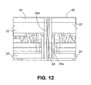
- FIG. 12 is a rear view of a pair of the electronic modules of FIGS. 1 and 2 adjacent one another sharing a common receptacle cage wall.
- a pluggable electronic module 1 includes a generally rectangular housing 2 , a printed circuit board 3 longitudinally extending therein, a hot-pluggable rear electrical connector 4 , and a front cable connector 5 .
- the rear electrical connector 4 can take any suitable form depending upon the type of mating electrical connector; however, the illustrated card edge connector is preferred.
- the illustrated front cable connector 5 is in the form of a block for receiving a multi-conductor cable 10 soldered to the printed circuit board 3 ; however, other front cable connectors can be provided depending upon the function of the module 1 , e.g.
- a bi-directional opto-electronic transceiver requires a duplex optical connector (LC or SC), a uni-directional opto-electronic module requires a single (LC or SC) connector.
- Conventional transceivers would also include some form of electro-optical converter, e.g. a photo-detector and/or a laser; however, copper transceivers do not.
- the electronic module 1 is slid into a host receptacle, e.g. a cage or guide rail, system with an electrical connector corresponding to the electrical connector 4 , which is mounted on a host printed circuit board in a host device.
- a de-latching mechanism 6 is mounted on the bottom of the housing 2 , and includes a latch 7 pivotally connected proximate the middle thereof to the housing 2 about a first axis defined by a first pivoting pin 8 .
- a lever preferably in the form of a bail handle 9 , extends around the front end of the housing 2 , and is pivotally connected to a first end of the latch 7 about a second axis, parallel to the first axis, defined by a second pivoting pin 11 .
- the bail handle 9 includes a pair of side arms 12 and 13 , lower ends of which are pivotally connected to the second pivoting pin 11 , and upper ends of which are connected to a cross bar 14 extending therebetween.
- the bail handle 9 can be replaced by a single arm or other form of lever.
- An eccentric projection 16 extends substantially perpendicularly from each of the lower ends of the side arms 12 and 13 , and includes a lower rounded surface 17 and an upper flat camming surface 18 (see FIG. 6 ).
- Each projection 16 extends into a recessed area 19 , in the housing 2 , which includes an abutment surface.
- each recessed area 19 is a rectangular step or indentation formed in the front end of the housing 2 , e.g. in the lower front corners of the cable connector block 5 .
- the lower rounded surface 17 enables the projection 16 , and therefore the bail handle 9 , to act like a first class lever and rotate about the second axis, i.e.
- the second pivoting pin 11 acting like a fulcrum, without contacting the wall of the housing 2 until the camming surface 18 engages the abutment surface, as seen in FIG. 2 .
- the bail handle 9 is not only able to pivot about the second axis; but, further force on the bail handle 9 causes the bail handle 9 to pivot about a third axis defined by the intersection of the camming surface 18 and the abutment surface.
- the bail handle 9 also becomes a second class lever with the fulcrum at the intersection of the camming surface 18 and the abutment surface, whereby any added force on the bail handle 9 is applied through the pivot pin 11 to the first end of the latch 7 , thereby pivoting the first end of the latch away from the housing 2 .
- a second end of the latch 7 includes a release arm 20 with a latching finger 21 , which engages a corresponding latching opening on the host cage or guide rail system. Pivoting the first end of the latch 7 away from the housing 2 into a release position ( FIG.
- the release arm 20 and the latching finger 21 causes the release arm 20 and the latching finger 21 to detract into an opening in the housing 2 , thereby releasing the latching finger 21 from the latching opening on the host cage enabling the transceiver 1 to be removed therefrom.
- the latch 7 In the latched position, the latch 7 is recessed into the housing 2 with only the latching finger 21 extending outwardly therefrom.
- the unlatched or release position the first end of the latch 7 is pivoted outwardly from the housing 2 , while the latching finger 21 is detracted further into the housing body, whereby the latching finger 21 no longer extends therefrom.
- the electronic module 1 in the form of a copper transceiver, is assembled by first connecting, e.g. soldering, an end of the multi-conductor cable 10 to the printed circuit board 3 , and mounting the assembly into either a housing bottom 22 or a housing top 23 , which combine to form the housing 2 .
- the housing bottom 22 and the housing top 23 are at least partially formed from a conductive material, and preferably comprise a cast metal.
- the housing top 23 includes a thin tail section 24 , and a pair of generally rectangular tapering ears 26 , i.e. tenons, extending therefrom for mating with the housing bottom 22 .
- the tail section 24 has smaller dimensions, i.e.
- a U-shaped bar 27 extends across the back of the housing bottom 22 providing a bearing surface and a hold-down bar for the thin tail section 24 of the housing top 23 .
- the tail section 24 is inserted under the bar 27 , and the housing top 23 is rotated down until the ears 26 are received in mating recesses 28 , i.e. mortises, in the housing bottom 22 (see FIG. 4 ).
- the first pin 8 is then inserted through holes 29 in the sides of the housing bottom 22 , through holes in the ears 26 , and through a bushing extending across the middle of the latch 7 , thereby securing the housing top 23 to the housing bottom 22 , and pivotally mounting the latch 7 to the housing bottom 22 .
- a spring 31 is positioned between the release arm 20 and the housing bottom 22 to spring bias the release arm 20 into a latched position, whereby a sufficient force must be applied to the bail handle 9 to overcome the spring force of the spring 31 to pivot the latch 7 into an unlatched or release position.
- a solid rectangular conductive projection 25 a extends outwardly from the housing bottom 22 for contacting the host receptacle and providing electromagnetic interference (EMI) protection.
- the projection 25 a extends rearwardly from the cable connector 5 longitudinally along the side of the housing bottom 22 .
- the projection 25 a includes a sloped rear ramp portion at a leading edger thereof, which gradually decreases in height from the front to the back of the housing 2 to facilitate insertion of the module into a host receptacle, whereby the walls of the cage will engage the ramp portion first and gradually ride up the ramp portion to the main body of the projections.
- solid rectangular projections 25 b and 25 c similar to projection 25 a , extend longitudinally along the top of the housing top 23 for contacting a top portion of a host receptacle.
- Another ramp 25 d extends along the side of the housing top 23 for added EMI protection. Projections 25 a and 25 d make the width to the housing 2 slightly larger than the width of the host receptacle, whereby the projections 25 a and 25 d frictionally engage the sides of the host receptacle.
- the next step in the assembly includes the insertion of the second pivoting pin 11 through a hole in the lower end of the side arm 12 , through a bushing in the end of the latch 7 , and through a hole in the lower end of the side arm 13 .
- the first and second pivoting pins 8 and 11 are identical to each other to simplify the supply and the assembly processes.
- the first and second pivoting pins 8 and 11 are tapered at the insertion end to facilitate insertion and part alignment, and have a flattened head at the other end for engaging a recessed annular wall in the countersunk hole 29 .
- the cross section of the first and second pivoting pins 8 and 11 changes from circular to oblong or oval, so that the major diameter of the oval is large enough to form a slight press fit with the hole 29 at the wall of the housing bottom 22 and of the side arm 12 . Accordingly, the final assembly step, see FIG.
- first and second pivoting pins 8 and 11 are forcing the head end of the first and second pivoting pins 8 and 11 into engagement with the side of the housing bottom 22 and the side arm 12 , respectively.
- the first and second pins 8 and 11 can be pressed out, if necessary, without damaging the housing bottom 22 or the first and second pins 8 and 11 , to facilitate repair or the recycling of parts.
- a patch cable 35 comprises the multi-conductor electrical cable 10 and copper transceivers 1 ′ and 1 ′′, similar to electronic module 1 , on either end thereof.
- Each of the copper transceivers 1 ′ and 1 ′′ includes the delatching mechanism 6 , as hereinbefore described with reference to FIGS. 1 to 7 . Since the cable 10 is permanently installed inside the copper transceivers 1 ′ and 1 ′′, it is imperative that each bail lever 9 need only be rotated through a small angle before unlatching the latch 7 .
- FIGS. 9 to 11 illustrate a second embodiment of a delatching mechanism 46 according to the present invention mounted on an electronic module 50 , including a bail handle 51 with first and second side arms 52 and 53 , and a cross bar 54 , pivoting about the second pivoting pin 11 .
- the remainder of the electronic module 50 is the same as the electronic module 1 , including the housing top and bottom 23 and 22 , respectively, with a multi-conductor electrical cable 10 extending therefrom.
- Each side arm 52 and 53 includes an elbow 55 and a horizontal arm section 56 , substantially perpendicular to the main side arm sections 52 and 53 , and extending along the top of the housing top 23 .
- the elbows 55 and the horizontal arm sections 56 effectively make the main side arms section 52 and 53 and the opening therebetween larger enabling the bail handle 51 to be rotated by a larger angle before contacting the cable 10 .
- a plurality of electronic modules can be disposed side-by-side, with the adjacent electronic modules 61 and 62 sharing the same cage wall 63 .
- electronic modules are equipped with projections 25 a and 25 d at the same height and position on both sides of the housing 2 , i.e. same horizontal plane, insertion and extraction of the modules 1 become very difficult as the projections 25 a on one side tend to bend the walls of the cage outwardly into the space designated for the projection of the adjacent module. Accordingly, the walls of the host receptacle will squeeze the module therebetween, requiring excessive force for insertion or extraction.
- a solution to the problem is to vertically offset the projections 25 a and 25 d on opposite sides of each housing 2 , so that the projections 25 a and 25 d are not in the same horizontal plane.
- a simple way to provide this vertical offset is to provide the projection 25 a on one side of the housing bottom 23 , and to provide the ramp 25 d on the opposite side of the housing top 22 .
- the lower projection 25 a of the module 61 is not directly adjacent the upper projection 25 d of the module 62 , thereby enabling the cage side wall 63 to bend in two vertically spaced apart places.
Landscapes
- Engineering & Computer Science (AREA)
- Microelectronics & Electronic Packaging (AREA)
- Physics & Mathematics (AREA)
- General Physics & Mathematics (AREA)
- Optics & Photonics (AREA)
- Details Of Connecting Devices For Male And Female Coupling (AREA)
Abstract
Description
-
- a housing having a first abutment surface;
- a printed circuit board mounted within the housing having an electrical connector at one end thereof for electrically connecting the module to a mating connector in the host receptacle;
- a latch pivotally connected to the housing about a first axis for releasably holding the module in the host receptacle;
- a lever pivotally connected to the latch about a second axis, the lever including a first camming surface;
- whereby the lever rotates about the second axis until the first camming surface abuts the first abutment surface, thereafter continued rotation of the lever causes rotation of the latch about the first axis for disengaging the latch from the host receptacle.
Claims (20)
Priority Applications (1)
| Application Number | Priority Date | Filing Date | Title |
|---|---|---|---|
| US11/251,720 US7090527B2 (en) | 2004-12-06 | 2005-10-17 | Transceiver delatching mechanism |
Applications Claiming Priority (2)
| Application Number | Priority Date | Filing Date | Title |
|---|---|---|---|
| US63364304P | 2004-12-06 | 2004-12-06 | |
| US11/251,720 US7090527B2 (en) | 2004-12-06 | 2005-10-17 | Transceiver delatching mechanism |
Publications (2)
| Publication Number | Publication Date |
|---|---|
| US20060121769A1 US20060121769A1 (en) | 2006-06-08 |
| US7090527B2 true US7090527B2 (en) | 2006-08-15 |
Family
ID=36935904
Family Applications (1)
| Application Number | Title | Priority Date | Filing Date |
|---|---|---|---|
| US11/251,720 Expired - Fee Related US7090527B2 (en) | 2004-12-06 | 2005-10-17 | Transceiver delatching mechanism |
Country Status (2)
| Country | Link |
|---|---|
| US (1) | US7090527B2 (en) |
| CN (1) | CN100477407C (en) |
Cited By (15)
| Publication number | Priority date | Publication date | Assignee | Title |
|---|---|---|---|---|
| US20060025786A1 (en) * | 1996-08-30 | 2006-02-02 | Verigen Transplantation Service International (Vtsi) Ag | Method for autologous transplantation |
| US20060078259A1 (en) * | 2004-10-12 | 2006-04-13 | Triquint Technology Holding Co. | Latching mechanism for small form factor pluggable modules |
| US20060118942A1 (en) * | 2002-08-06 | 2006-06-08 | Schmidt William L | Optoelectric module with handle-based delatching mechanism |
| US20060176658A1 (en) * | 2005-02-04 | 2006-08-10 | Hardt Thomas T | Latching mechanism |
| US20090176401A1 (en) * | 2008-01-07 | 2009-07-09 | Applied Optoelectronics, Inc. | Pluggable form factor release mechanism |
| US20100091466A1 (en) * | 2008-10-14 | 2010-04-15 | Hon Hai Precision Ind. Co., Ltd. | Electronic module with ejector mechanism |
| US20110304996A1 (en) * | 2010-06-10 | 2011-12-15 | Hon Hai Precision Industry Co., Ltd. | Electronic module with improved printed circuit board to maximize width thereof |
| US20120058651A1 (en) * | 2010-09-08 | 2012-03-08 | Hon Hai Precision Industry Co., Ltd. | Connector having an improved cover |
| US20120064754A1 (en) * | 2010-09-13 | 2012-03-15 | Hitachi Cable, Ltd. | Direct attach cable |
| US20120063100A1 (en) * | 2010-09-15 | 2012-03-15 | Hon Hai Precision Industry Co., Ltd. | Electronic module with improved latch mechanism |
| CN101783462B (en) * | 2010-01-27 | 2013-02-13 | 深圳市德仓科技有限公司 | Electric connector |
| US20130120946A1 (en) * | 2011-11-14 | 2013-05-16 | Rockwell Automation Technologies, Inc. | Systems and methods for manufacturing industrial automation drives |
| US20150318634A1 (en) * | 2014-04-30 | 2015-11-05 | Tyco Electronics Corporation | Pluggable connector having multiple housing shells |
| US10855041B2 (en) * | 2018-09-28 | 2020-12-01 | Optomedia Technology Inc. | Optical to electrical adapter |
| US11385425B2 (en) * | 2020-01-03 | 2022-07-12 | Solid, Inc. | Optical module assembly |
Families Citing this family (16)
| Publication number | Priority date | Publication date | Assignee | Title |
|---|---|---|---|---|
| JP2007305537A (en) * | 2006-05-15 | 2007-11-22 | Three M Innovative Properties Co | Connector |
| US7351090B1 (en) * | 2006-11-30 | 2008-04-01 | Finisar Corporation | Latching mechanism for a module |
| TWI387411B (en) * | 2007-02-28 | 2013-02-21 | Finisar Corp | Printed circuit board positioning mechanism |
| US7429185B1 (en) * | 2007-08-31 | 2008-09-30 | Hon Hai Precision Ind. Co., Ltd. | Plug-in module with latch mechanism |
| CN101672957A (en) | 2008-09-12 | 2010-03-17 | 鸿富锦精密工业(深圳)有限公司 | Miniature pluggable module and releasing mechanism thereof |
| US20110268390A1 (en) * | 2010-05-01 | 2011-11-03 | Avago Technologies Fiber Ip (Singapore) Pte. Ltd. | Active optical cable that is suited for consumer applications and a method |
| US8708577B2 (en) * | 2010-05-17 | 2014-04-29 | E-Band Communications, LLC. | Small form-factor pluggable connector system |
| CN102377057B (en) * | 2010-08-16 | 2015-07-08 | 富士康(昆山)电脑接插件有限公司 | Connector component |
| CN102998755A (en) * | 2012-10-16 | 2013-03-27 | 绍兴飞泰光电技术有限公司 | Coarse identical-wavelength division multiplexing bidirectional light receiving and transmitting integrated module with tail fiber type structure and single fiber |
| US9250402B2 (en) * | 2013-02-05 | 2016-02-02 | Sumitomo Electric Industries, Ltd. | Pluggable optical transceiver having pull-pull-tab |
| CN106165207B (en) * | 2014-02-06 | 2019-11-15 | 富加宜(亚洲)私人有限公司 | Connector assembly |
| EP3514973B1 (en) * | 2018-01-18 | 2020-08-12 | Axcen Photonics Corp. | Small form-factor pluggable transceiver |
| EP3514974B1 (en) * | 2018-01-18 | 2021-06-23 | Axcen Photonics Corp. | Small form-factor pluggable transceiver |
| EP3514972B1 (en) * | 2018-01-18 | 2020-08-12 | Axcen Photonics Corp. | Small form-factor pluggable transceiver |
| MX2021004063A (en) * | 2018-10-11 | 2021-06-04 | Masimo Corp | Patient connector assembly with vertical detents. |
| US10534144B1 (en) * | 2019-05-17 | 2020-01-14 | Prime World International Holdings Ltd. | Optical transceiver |
Citations (14)
| Publication number | Priority date | Publication date | Assignee | Title |
|---|---|---|---|---|
| US5901263A (en) | 1997-09-12 | 1999-05-04 | International Business Machines Corporation | Hot pluggable module integrated lock/extraction tool |
| US6439918B1 (en) | 2001-10-04 | 2002-08-27 | Finisar Corporation | Electronic module having an integrated latching mechanism |
| US6652306B2 (en) * | 2001-05-24 | 2003-11-25 | Yazaki Corporation | Power feeding connector apparatus |
| US6692159B2 (en) | 2001-04-14 | 2004-02-17 | E20 Communications, Inc. | De-latching mechanisms for fiber optic modules |
| US6744963B2 (en) | 2002-02-20 | 2004-06-01 | Hon Hai Precision Ind. Co., Ltd. | Optoelectrical transceiver module with de-latching mechanism |
| US6789958B2 (en) | 2001-08-31 | 2004-09-14 | Infineon Technologies Ag | Release mechanism for pluggable fiber optic transceiver |
| US6840680B1 (en) | 2001-04-14 | 2005-01-11 | Jds Uniphase Corporation | Retention and release mechanisms for fiber optic modules |
| US6851867B2 (en) | 2001-04-14 | 2005-02-08 | Jds Uniphase Corporation | Cam-follower release mechanism for fiber optic modules with side delatching mechanisms |
| US6890206B2 (en) | 2002-03-05 | 2005-05-10 | Jds Uniphase Corporation | Optical transceiver latch |
| US6899556B2 (en) * | 2002-06-06 | 2005-05-31 | J.S.T. Mfg. Co., Ltd. | Electrical connection system |
| US6916123B2 (en) * | 2002-09-10 | 2005-07-12 | Jds Uniphase Corporation | Unlatching mechanism for an optical transceiver |
| US6927973B2 (en) * | 2001-06-05 | 2005-08-09 | Idis Co., Ltd. | Device for joining and separating storage medium |
| US6929403B1 (en) * | 2003-02-10 | 2005-08-16 | Opnext, Inc. | Small form-factor pluggable bail latch |
| US6945809B2 (en) * | 2003-01-21 | 2005-09-20 | Hitachi Cable, Ltd. | Package with lock mechanism |
-
2005
- 2005-10-17 US US11/251,720 patent/US7090527B2/en not_active Expired - Fee Related
- 2005-12-06 CN CNB2005101277879A patent/CN100477407C/en not_active Expired - Fee Related
Patent Citations (14)
| Publication number | Priority date | Publication date | Assignee | Title |
|---|---|---|---|---|
| US5901263A (en) | 1997-09-12 | 1999-05-04 | International Business Machines Corporation | Hot pluggable module integrated lock/extraction tool |
| US6840680B1 (en) | 2001-04-14 | 2005-01-11 | Jds Uniphase Corporation | Retention and release mechanisms for fiber optic modules |
| US6692159B2 (en) | 2001-04-14 | 2004-02-17 | E20 Communications, Inc. | De-latching mechanisms for fiber optic modules |
| US6851867B2 (en) | 2001-04-14 | 2005-02-08 | Jds Uniphase Corporation | Cam-follower release mechanism for fiber optic modules with side delatching mechanisms |
| US6652306B2 (en) * | 2001-05-24 | 2003-11-25 | Yazaki Corporation | Power feeding connector apparatus |
| US6927973B2 (en) * | 2001-06-05 | 2005-08-09 | Idis Co., Ltd. | Device for joining and separating storage medium |
| US6789958B2 (en) | 2001-08-31 | 2004-09-14 | Infineon Technologies Ag | Release mechanism for pluggable fiber optic transceiver |
| US6439918B1 (en) | 2001-10-04 | 2002-08-27 | Finisar Corporation | Electronic module having an integrated latching mechanism |
| US6744963B2 (en) | 2002-02-20 | 2004-06-01 | Hon Hai Precision Ind. Co., Ltd. | Optoelectrical transceiver module with de-latching mechanism |
| US6890206B2 (en) | 2002-03-05 | 2005-05-10 | Jds Uniphase Corporation | Optical transceiver latch |
| US6899556B2 (en) * | 2002-06-06 | 2005-05-31 | J.S.T. Mfg. Co., Ltd. | Electrical connection system |
| US6916123B2 (en) * | 2002-09-10 | 2005-07-12 | Jds Uniphase Corporation | Unlatching mechanism for an optical transceiver |
| US6945809B2 (en) * | 2003-01-21 | 2005-09-20 | Hitachi Cable, Ltd. | Package with lock mechanism |
| US6929403B1 (en) * | 2003-02-10 | 2005-08-16 | Opnext, Inc. | Small form-factor pluggable bail latch |
Cited By (23)
| Publication number | Priority date | Publication date | Assignee | Title |
|---|---|---|---|---|
| US20060025786A1 (en) * | 1996-08-30 | 2006-02-02 | Verigen Transplantation Service International (Vtsi) Ag | Method for autologous transplantation |
| US20060118942A1 (en) * | 2002-08-06 | 2006-06-08 | Schmidt William L | Optoelectric module with handle-based delatching mechanism |
| US20060078259A1 (en) * | 2004-10-12 | 2006-04-13 | Triquint Technology Holding Co. | Latching mechanism for small form factor pluggable modules |
| US20060176658A1 (en) * | 2005-02-04 | 2006-08-10 | Hardt Thomas T | Latching mechanism |
| US7349200B2 (en) * | 2005-02-04 | 2008-03-25 | Hewlett-Packard Development Company, L.P. | Latching mechanism |
| US20090176401A1 (en) * | 2008-01-07 | 2009-07-09 | Applied Optoelectronics, Inc. | Pluggable form factor release mechanism |
| US7766686B2 (en) * | 2008-01-07 | 2010-08-03 | Applied Optoelectronics, Inc. | Pluggable form factor release mechanism |
| US20100091466A1 (en) * | 2008-10-14 | 2010-04-15 | Hon Hai Precision Ind. Co., Ltd. | Electronic module with ejector mechanism |
| US8064207B2 (en) * | 2008-10-14 | 2011-11-22 | Hon Hai Precision Ind. Co., Ltd. | Electronic module with ejector mechanism |
| CN101783462B (en) * | 2010-01-27 | 2013-02-13 | 深圳市德仓科技有限公司 | Electric connector |
| US20110304996A1 (en) * | 2010-06-10 | 2011-12-15 | Hon Hai Precision Industry Co., Ltd. | Electronic module with improved printed circuit board to maximize width thereof |
| US8599567B2 (en) * | 2010-06-10 | 2013-12-03 | Hon Hai Precision Industry Co., Ltd. | Electronic module with improved printed circuit board to maximize width thereof |
| US20120058651A1 (en) * | 2010-09-08 | 2012-03-08 | Hon Hai Precision Industry Co., Ltd. | Connector having an improved cover |
| US8388367B2 (en) * | 2010-09-13 | 2013-03-05 | Hitachi Cable, Ltd. | Direct attach cable |
| US20120064754A1 (en) * | 2010-09-13 | 2012-03-15 | Hitachi Cable, Ltd. | Direct attach cable |
| US20120063100A1 (en) * | 2010-09-15 | 2012-03-15 | Hon Hai Precision Industry Co., Ltd. | Electronic module with improved latch mechanism |
| US8537558B2 (en) * | 2010-09-15 | 2013-09-17 | Hon Hai Precision Industry Co., Ltd. | Electronic module with improved latch mechanism |
| US20130120946A1 (en) * | 2011-11-14 | 2013-05-16 | Rockwell Automation Technologies, Inc. | Systems and methods for manufacturing industrial automation drives |
| US9351420B2 (en) * | 2011-11-14 | 2016-05-24 | Rockwell Automation Technologies, Inc. | Systems and methods for manufacturing industrial automation drives |
| US20150318634A1 (en) * | 2014-04-30 | 2015-11-05 | Tyco Electronics Corporation | Pluggable connector having multiple housing shells |
| US9419367B2 (en) * | 2014-04-30 | 2016-08-16 | Tyco Electronics Corporation | Pluggable connector having multiple housing shells |
| US10855041B2 (en) * | 2018-09-28 | 2020-12-01 | Optomedia Technology Inc. | Optical to electrical adapter |
| US11385425B2 (en) * | 2020-01-03 | 2022-07-12 | Solid, Inc. | Optical module assembly |
Also Published As
| Publication number | Publication date |
|---|---|
| US20060121769A1 (en) | 2006-06-08 |
| CN1825151A (en) | 2006-08-30 |
| CN100477407C (en) | 2009-04-08 |
Similar Documents
| Publication | Publication Date | Title |
|---|---|---|
| US7090527B2 (en) | Transceiver delatching mechanism | |
| US7056156B1 (en) | Vertically offset EMI projections | |
| JP3131837B2 (en) | Connector device | |
| US6550977B2 (en) | Apparatus for connecting optical connectors and printed circuit board, unit mounting the same | |
| US6304436B1 (en) | Connector system with outwardly opening door for a removable transceiver module | |
| US6890206B2 (en) | Optical transceiver latch | |
| US9277673B2 (en) | Connector assembly | |
| US8023270B2 (en) | Optoelectronic transceiver assembly and release mechanism employed therein | |
| US7433193B2 (en) | Techniques for controlling a position of a transceiver module relative to a connector | |
| US6698937B2 (en) | Optical connector mechanism | |
| US20050041407A1 (en) | Pluggable video module | |
| JP2005196213A (en) | Transceiver module assembly | |
| US6886992B2 (en) | Fiber optic connector module having rear extender | |
| US7220066B2 (en) | Pluggable optical transceiver module assembly | |
| US6988834B2 (en) | Fiber optic connector module | |
| US7204710B1 (en) | SFP module mounting structure | |
| US7377702B2 (en) | Cageless, pluggable optoelectronic device which enables belly-to-belly layouts | |
| US20120170890A1 (en) | Miniature Pluggable Video Module | |
| US20050227518A1 (en) | Pluggable transceiver with cover resilient member | |
| US20040087193A1 (en) | Connector coupling mechanism, system and method | |
| US7211728B2 (en) | Optical cage system preventing insertion of incorrect module | |
| US9583862B1 (en) | Connector assembly and retention mechanism configured to maintain a mated relationship | |
| CN110768727B (en) | Optical transceiver | |
| US9176290B2 (en) | Miniature pluggable video module | |
| CN216118103U (en) | Optical module |
Legal Events
| Date | Code | Title | Description |
|---|---|---|---|
| AS | Assignment |
Owner name: JDS UNIPHASE CORPORATION, CALIFORNIA Free format text: ASSIGNMENT OF ASSIGNORS INTEREST;ASSIGNORS:HANLEY, MICHAEL FRANCIS;MOON, JAMES ROBERT;KRUGER, BRUCE P.;AND OTHERS;REEL/FRAME:017101/0323 Effective date: 20051004 |
|
| FPAY | Fee payment |
Year of fee payment: 4 |
|
| FPAY | Fee payment |
Year of fee payment: 8 |
|
| AS | Assignment |
Owner name: LUMENTUM OPERATIONS LLC, CALIFORNIA Free format text: ASSIGNMENT OF ASSIGNORS INTEREST;ASSIGNOR:JDS UNIPHASE CORPORATION;REEL/FRAME:036420/0340 Effective date: 20150731 |
|
| FEPP | Fee payment procedure |
Free format text: PAYOR NUMBER ASSIGNED (ORIGINAL EVENT CODE: ASPN); ENTITY STATUS OF PATENT OWNER: LARGE ENTITY |
|
| AS | Assignment |
Owner name: LUMENTUM OPERATIONS LLC, CALIFORNIA Free format text: CORRECTIVE ASSIGNMENT TO CORRECT THE PATENTS LISTED ON PAGE A-A33 PREVIOUSLY RECORDED ON REEL 036420 FRAME 0340. ASSIGNOR(S) HEREBY CONFIRMS THE PATENT NUMBERS 7,868,247 AND 6,476,312 WERE LISTED IN ERROR AND SHOULD BE REMOVED;ASSIGNOR:JDS UNIPHASE CORPORATION;REEL/FRAME:037562/0513 Effective date: 20150731 Owner name: LUMENTUM OPERATIONS LLC, CALIFORNIA Free format text: CORRECTIVE ASSIGNMENT TO CORRECT INCORRECT PATENTS 7,868,247 AND 6,476,312 ON PAGE A-A33 PREVIOUSLY RECORDED ON REEL 036420 FRAME 0340. ASSIGNOR(S) HEREBY CONFIRMS THE ASSIGNMENT;ASSIGNOR:JDS UNIPHASE CORPORATION;REEL/FRAME:037562/0513 Effective date: 20150731 |
|
| AS | Assignment |
Owner name: LUMENTUM OPERATIONS LLC, CALIFORNIA Free format text: CORRECTIVE ASSIGNMENT TO CORRECT THE PATENTS LISTED ON PAGE A-A33 PATENT NUMBERS 7,868,247 AND 6,476,312 WERE LISTED IN ERROR AND SHOULD BE REMOVED. PREVIOUSLY RECORDED ON REEL 036420 FRAME 0340. ASSIGNOR(S) HEREBY CONFIRMS THE ASSIGNMENT;ASSIGNOR:JDS UNIPHASE CORPORATION;REEL/FRAME:037627/0641 Effective date: 20150731 Owner name: LUMENTUM OPERATIONS LLC, CALIFORNIA Free format text: CORRECTIVE ASSIGNMENT TO CORRECT PATENTS 7,868,247 AND 6,476,312 LISTED ON PAGE A-A33 PREVIOUSLY RECORDED ON REEL 036420 FRAME 0340. ASSIGNOR(S) HEREBY CONFIRMS THE ASSIGNMENT;ASSIGNOR:JDS UNIPHASE CORPORATION;REEL/FRAME:037627/0641 Effective date: 20150731 |
|
| FEPP | Fee payment procedure |
Free format text: PAYER NUMBER DE-ASSIGNED (ORIGINAL EVENT CODE: RMPN); ENTITY STATUS OF PATENT OWNER: LARGE ENTITY Free format text: PAYOR NUMBER ASSIGNED (ORIGINAL EVENT CODE: ASPN); ENTITY STATUS OF PATENT OWNER: LARGE ENTITY |
|
| FEPP | Fee payment procedure |
Free format text: MAINTENANCE FEE REMINDER MAILED (ORIGINAL EVENT CODE: REM.) |
|
| LAPS | Lapse for failure to pay maintenance fees |
Free format text: PATENT EXPIRED FOR FAILURE TO PAY MAINTENANCE FEES (ORIGINAL EVENT CODE: EXP.); ENTITY STATUS OF PATENT OWNER: LARGE ENTITY |
|
| STCH | Information on status: patent discontinuation |
Free format text: PATENT EXPIRED DUE TO NONPAYMENT OF MAINTENANCE FEES UNDER 37 CFR 1.362 |
|
| FP | Lapsed due to failure to pay maintenance fee |
Effective date: 20180815 |
|
| AS | Assignment |
Owner name: DEUTSCHE BANK AG NEW YORK BRANCH, AS COLLATERAL AGENT, NEW YORK Free format text: PATENT SECURITY AGREEMENT;ASSIGNORS:LUMENTUM OPERATIONS LLC;OCLARO FIBER OPTICS, INC.;OCLARO, INC.;REEL/FRAME:047788/0511 Effective date: 20181210 Owner name: DEUTSCHE BANK AG NEW YORK BRANCH, AS COLLATERAL AG Free format text: PATENT SECURITY AGREEMENT;ASSIGNORS:LUMENTUM OPERATIONS LLC;OCLARO FIBER OPTICS, INC.;OCLARO, INC.;REEL/FRAME:047788/0511 Effective date: 20181210 |
|
| AS | Assignment |
Owner name: LUMENTUM OPERATIONS LLC, CALIFORNIA Free format text: RELEASE BY SECURED PARTY;ASSIGNOR:DEUTSCHE AG NEW YORK BRANCH;REEL/FRAME:051287/0556 Effective date: 20191212 Owner name: OCLARO, INC., CALIFORNIA Free format text: RELEASE BY SECURED PARTY;ASSIGNOR:DEUTSCHE AG NEW YORK BRANCH;REEL/FRAME:051287/0556 Effective date: 20191212 Owner name: OCLARO FIBER OPTICS, INC., CALIFORNIA Free format text: RELEASE BY SECURED PARTY;ASSIGNOR:DEUTSCHE AG NEW YORK BRANCH;REEL/FRAME:051287/0556 Effective date: 20191212 |