US7092531B2 - Sound output apparatus for an automotive vehicle - Google Patents
Sound output apparatus for an automotive vehicle Download PDFInfo
- Publication number
- US7092531B2 US7092531B2 US10/353,911 US35391103A US7092531B2 US 7092531 B2 US7092531 B2 US 7092531B2 US 35391103 A US35391103 A US 35391103A US 7092531 B2 US7092531 B2 US 7092531B2
- Authority
- US
- United States
- Prior art keywords
- sound
- automotive vehicle
- sound output
- generating means
- loudspeakers
- Prior art date
- Legal status (The legal status is an assumption and is not a legal conclusion. Google has not performed a legal analysis and makes no representation as to the accuracy of the status listed.)
- Expired - Fee Related
Links
Images


Classifications
-
- B—PERFORMING OPERATIONS; TRANSPORTING
- B60—VEHICLES IN GENERAL
- B60R—VEHICLES, VEHICLE FITTINGS, OR VEHICLE PARTS, NOT OTHERWISE PROVIDED FOR
- B60R11/00—Arrangements for holding or mounting articles, not otherwise provided for
- B60R11/02—Arrangements for holding or mounting articles, not otherwise provided for for radio sets, television sets, telephones, or the like; Arrangement of controls thereof
- B60R11/0217—Arrangements for holding or mounting articles, not otherwise provided for for radio sets, television sets, telephones, or the like; Arrangement of controls thereof for loud-speakers
-
- H—ELECTRICITY
- H04—ELECTRIC COMMUNICATION TECHNIQUE
- H04R—LOUDSPEAKERS, MICROPHONES, GRAMOPHONE PICK-UPS OR LIKE ACOUSTIC ELECTROMECHANICAL TRANSDUCERS; DEAF-AID SETS; PUBLIC ADDRESS SYSTEMS
- H04R1/00—Details of transducers, loudspeakers or microphones
- H04R1/20—Arrangements for obtaining desired frequency or directional characteristics
- H04R1/32—Arrangements for obtaining desired frequency or directional characteristics for obtaining desired directional characteristic only
- H04R1/40—Arrangements for obtaining desired frequency or directional characteristics for obtaining desired directional characteristic only by combining a number of identical transducers
- H04R1/403—Arrangements for obtaining desired frequency or directional characteristics for obtaining desired directional characteristic only by combining a number of identical transducers loud-speakers
-
- H—ELECTRICITY
- H04—ELECTRIC COMMUNICATION TECHNIQUE
- H04R—LOUDSPEAKERS, MICROPHONES, GRAMOPHONE PICK-UPS OR LIKE ACOUSTIC ELECTROMECHANICAL TRANSDUCERS; DEAF-AID SETS; PUBLIC ADDRESS SYSTEMS
- H04R3/00—Circuits for transducers, loudspeakers or microphones
- H04R3/12—Circuits for transducers, loudspeakers or microphones for distributing signals to two or more loudspeakers
-
- B—PERFORMING OPERATIONS; TRANSPORTING
- B60—VEHICLES IN GENERAL
- B60R—VEHICLES, VEHICLE FITTINGS, OR VEHICLE PARTS, NOT OTHERWISE PROVIDED FOR
- B60R11/00—Arrangements for holding or mounting articles, not otherwise provided for
- B60R2011/0001—Arrangements for holding or mounting articles, not otherwise provided for characterised by position
- B60R2011/0003—Arrangements for holding or mounting articles, not otherwise provided for characterised by position inside the vehicle
- B60R2011/0005—Dashboard
-
- B—PERFORMING OPERATIONS; TRANSPORTING
- B60—VEHICLES IN GENERAL
- B60R—VEHICLES, VEHICLE FITTINGS, OR VEHICLE PARTS, NOT OTHERWISE PROVIDED FOR
- B60R11/00—Arrangements for holding or mounting articles, not otherwise provided for
- B60R2011/0001—Arrangements for holding or mounting articles, not otherwise provided for characterised by position
- B60R2011/0003—Arrangements for holding or mounting articles, not otherwise provided for characterised by position inside the vehicle
- B60R2011/001—Vehicle control means, e.g. steering-wheel or column
-
- B—PERFORMING OPERATIONS; TRANSPORTING
- B60—VEHICLES IN GENERAL
- B60R—VEHICLES, VEHICLE FITTINGS, OR VEHICLE PARTS, NOT OTHERWISE PROVIDED FOR
- B60R11/00—Arrangements for holding or mounting articles, not otherwise provided for
- B60R2011/0001—Arrangements for holding or mounting articles, not otherwise provided for characterised by position
- B60R2011/0003—Arrangements for holding or mounting articles, not otherwise provided for characterised by position inside the vehicle
- B60R2011/0012—Seats or parts thereof
- B60R2011/0015—Back-rests
-
- B—PERFORMING OPERATIONS; TRANSPORTING
- B60—VEHICLES IN GENERAL
- B60R—VEHICLES, VEHICLE FITTINGS, OR VEHICLE PARTS, NOT OTHERWISE PROVIDED FOR
- B60R11/00—Arrangements for holding or mounting articles, not otherwise provided for
- B60R2011/0001—Arrangements for holding or mounting articles, not otherwise provided for characterised by position
- B60R2011/0003—Arrangements for holding or mounting articles, not otherwise provided for characterised by position inside the vehicle
- B60R2011/0012—Seats or parts thereof
- B60R2011/0017—Head-rests
-
- B—PERFORMING OPERATIONS; TRANSPORTING
- B60—VEHICLES IN GENERAL
- B60R—VEHICLES, VEHICLE FITTINGS, OR VEHICLE PARTS, NOT OTHERWISE PROVIDED FOR
- B60R11/00—Arrangements for holding or mounting articles, not otherwise provided for
- B60R2011/0001—Arrangements for holding or mounting articles, not otherwise provided for characterised by position
- B60R2011/0003—Arrangements for holding or mounting articles, not otherwise provided for characterised by position inside the vehicle
- B60R2011/0028—Ceiling, e.g. roof rails
-
- H—ELECTRICITY
- H04—ELECTRIC COMMUNICATION TECHNIQUE
- H04R—LOUDSPEAKERS, MICROPHONES, GRAMOPHONE PICK-UPS OR LIKE ACOUSTIC ELECTROMECHANICAL TRANSDUCERS; DEAF-AID SETS; PUBLIC ADDRESS SYSTEMS
- H04R2499/00—Aspects covered by H04R or H04S not otherwise provided for in their subgroups
- H04R2499/10—General applications
- H04R2499/13—Acoustic transducers and sound field adaptation in vehicles
Definitions
- This invention relates to a sound output apparatus for an automotive vehicle which generates various acoustic or sound outputs, such as warning sounds, alarms, guide voice or speech, and others.
- an automotive vehicle is equipped with an acoustic or sound device for generating various acoustic or sound outputs to transmit necessary information to a driver or passengers in a passenger compartment.
- various sensors are installed on an automotive vehicle to detect dangerous or abnormal conditions of the vehicle. When these sensors detect any dangerous or abnormal conditions of the vehicle, warning sounds, alarms, and voice or speech guidance from a navigation system will be generated to evoke driver's or passenger's caution and to let the driver or passengers act or behave appropriately to avoid the encountering danger or abnormality.
- warning sounds or alarms are generated, there will be the possibility that a driver or passenger cannot understand the contents or meaning of the immediately generating warning sounds or alarms and also cannot know the direction to which the driver's or passenger's caution should be directed. Hence, the action or behavior of the driver or passengers to avoid the encountering danger or abnormality will be delayed.
- supersonic sonars may be installed at four corners of a vehicle body to detect approach of any obstacle.
- the warning sounds or alarms notifying the approach of any obstacle are always the same, a driver or passengers will not be able to immediately know or perceive the direction from which the detected obstacle is approaching. The driver and passengers will not be able to promptly and properly respond to avoid the coming danger or increasing abnormality.
- Japanese Patent Application Laid-open No. 2002-133596 discloses a warning apparatus which produces a virtual sound source by using loudspeakers installed in a passenger compartment and changes the position of the virtual sound source or tone quality in accordance with time variation or spatial or positional change of a distance between oneself and the car ahead or behind, thereby letting a driver sense the position of other vehicle.
- production of the virtual sound source is realized by using a multichannel surround system consisting of four channel loudspeakers disposed at four corners, i.e., right and left edges of respective front and rear ends, in a passenger compartment, or by using a stereo dipole system consisting of a pair of loudspeakers disposed adjacently to each other which is preferably incorporated in a car navigation system.
- the stereo dipole system has a very wide audible area in which clear acoustic or sound image localization is attained. Furthermore, as two loudspeakers are disposed adjacently to each other, the stereo dipole system can be preferable employed as an acoustic equipment installed in a narrow or limited space available in a passenger compartment.
- a pair of loudspeakers SP is disposed in front of an audience with an angle ⁇ formed between two straight lines connecting respective loudspeakers SP to the audience.
- the required angle ⁇ is approximately 10°.
- the loudspeakers incorporated in a car navigation system are usually positioned in a central region on an instrument panel or a dashboard substantially equally distant from each of a driver's seat and the next passenger's seat.
- the loudspeakers of a car navigation system are not positioned in direct front of the driver's seat or in direct front of the passenger's seat. Therefore, it is difficult to obtain clear acoustic or sound image localization by using a car navigation system even if the stereo dipole system is employed. If the loudspeakers are downsized in the future, the above distance L may be too long to obtain clear acoustic or sound image localization.
- the present invention has an object to provide a sound output apparatus for an automotive vehicle which generates a virtual sound source in a passenger compartment based on a stereo dipole system and is capable of obtaining clear acoustic or sound image localization even when used loudspeakers are small or compact.
- Another object of the present invention is to provide a sound output apparatus for an automotive vehicle which is capable of obtaining clear acoustic or sound image localization covering all of the angular regions including the back side of a driver or a passenger.
- the present invention provides a sound output apparatus for an automotive vehicle including a sound generating means for generating sounds and an acoustic signal producing means for generating acoustic signals to be supplied to the sound generating means.
- the acoustic signal producing means receives sound output requirements and identifies output sounds to be generated from the sound generating means as well as an alerting direction to which attention of a designated person should be directed.
- the acoustic signal producing means generates the acoustic signals to be supplied to the sound generating means so that the output sounds cooperatively obtain acoustic image localization in such a manner that a virtual sound source is positioned at a location corresponding to the alerting direction.
- the sound generating means includes at least a pair of loudspeakers disposed adjacently to each other, and is installed to a predetermined portion of at least a designated seat on which the designated person sits.
- the sound generating means is positioned on a symmetry axis of the designated seat.
- the sound generating means is positioned inside the designated seat.
- the designated seat has a plurality of through-holes or openings provided in the vicinity of the sound generating means.
- the sound generating means is positioned on a shoulder of the designated seat.
- the sound generating means is positioned on a top of a headrest constituting an upper part of the designated seat.
- the sound generating means is positioned at a back side of a seatback of the designated seat.
- the sound generating means is positioned beneath a seat bottom of the designated seat.
- the designated seat is a driver's seat.
- the sound generating means has a sound output surface facing a front side of the automotive vehicle.
- the sound generating means further includes a pair of loudspeakers disposed adjacently to each other and installed on a ceiling or a sun visor attached near an upper edge of a front windshield glass.
- the loudspeakers installed on the ceiling or the sun visor have sound output surfaces facing a rear side of the automotive vehicle.
- the sound generating means further includes a pair of loudspeakers disposed beneath an instrument panel or a dashboard or attached to a steering support provided for rotatably supporting a steering wheel.
- the loudspeakers, disposed beneath the instrument panel or the dashboard or attached to the steering support have sound output surfaces facing a rear side of the automotive vehicle.
- the sound generating means further includes a pair of loudspeakers installed on a steering wheel so as to have sound output surfaces facing a rear side of the automotive vehicle.
- the acoustic signal producing means includes correcting means for correcting the acoustic signals based on a steering angle of the steering wheel and supplying corrected acoustic signals to the sound generating means.
- the sound generating means includes flat panel loudspeakers or micro loudspeakers.
- the acoustic signal producing means performs radio communication to transmit the acoustic signals or the corrected acoustic signals to the sound generating means.
- a sound output apparatus for an automotive vehicle, including a sound generating means for generating sounds and an acoustic signal producing means for generating acoustic signals to be supplied to the sound generating means.
- the acoustic signal producing means receives sound output requirements and identifies output sounds to be generated from the sound generating means as well as an alerting direction to which attention of a designated person should be directed.
- the acoustic signal producing means generates the acoustic signals to be supplied to the sound generating means so that the output sounds cooperatively obtain acoustic image localization in such a manner that a virtual sound source is positioned at a location corresponding to the alerting direction.
- the sound generating means includes at least a pair of loudspeakers disposed adjacently to each other, and is installed on at least a designated seat positioned in front of a seat on which the designated person sits.
- FIG. 1 is a block diagram showing a schematic arrangement of a sound output apparatus in accordance with a first embodiment of the present invention
- FIG. 2A is a block diagram showing an arrangement of an acoustic signal supplying section in accordance with the first embodiment of the present invention
- FIG. 2B is a block diagram showing an arrangement of another acoustic signal supplying section in accordance with the first embodiment of the present invention
- FIG. 3A is a perspective view showing an output section installed in a seat of an automotive vehicle in accordance with the first embodiment of the present invention
- FIG. 3B is a perspective view showing a seatback board covering the output section installed in a seat of an automotive vehicle in accordance with the first embodiment of the present invention
- FIG. 3C is a perspective view showing another seatback board covering the output section installed in a seat of an automotive vehicle in accordance with the first embodiment of the present invention
- FIG. 4A is a perspective view showing the output section installed inside a seatback of an automotive vehicle in accordance with the first embodiment of the present invention
- FIG. 4B is a side view showing the direction of a sound output surface of the output section installed in a seatback of an automotive vehicle in accordance with the first embodiment of the present invention
- FIG. 4C is a side view showing another direction of the sound output surface of the output section installed in a seatback of an automotive vehicle in accordance with the first embodiment of the present invention
- FIG. 5A is a block diagram showing a schematic arrangement of a sound output apparatus in accordance with a second embodiment of the present invention.
- FIG. 5B is a block diagram showing a schematic arrangement of another sound output apparatus in accordance with the second embodiment of the present invention.
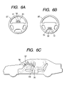
- FIG. 6A is a front view showing an output section installed on an upper portion of a steering wheel of an automotive vehicle in accordance with the second embodiment of the present invention
- FIG. 6B is a front view showing another output section installed on a lower portion of a steering wheel of an automotive vehicle in accordance with the second embodiment of the present invention.
- FIG. 6C is a side view showing the direction of a sound output surface of the output section installed on the steering wheel of an automotive vehicle in accordance with the second embodiment of the present invention.
- FIG. 7A is a side view showing another output section installed beneath a dashboard of an automotive vehicle and the direction of a sound output surface of this output section in accordance with the second embodiment of the present invention
- FIG. 7B is a side view showing another output section installed on a ceiling of an automotive vehicle and the direction of a sound output surface of this output section in accordance with the second embodiment of the present invention
- FIG. 8A is a block diagram showing a schematic arrangement of a sound output apparatus in accordance with a third embodiment of the present invention.
- FIG. 8B is a block diagram showing a schematic arrangement of another sound output apparatus in accordance with the third embodiment of the present invention.
- FIG. 9A is a perspective view showing an output section installed inside a seat bottom of an automotive vehicle in accordance with other embodiment of the present invention.
- FIG. 9B is a side view showing the direction of a sound output surface of the output section installed inside a seat bottom of an automotive vehicle in accordance with the embodiment shown in FIG. 9A ;
- FIG. 9C is a side view showing another direction of the sound output surface of the output section installed in a seat bottom of an automotive vehicle in accordance with the embodiment shown in FIG. 9A ;
- FIG. 10A is a perspective view showing another output section installed beneath a seat bottom of an automotive vehicle in accordance with other embodiment of the present invention.
- FIG. 10B is a side view showing the direction of a sound output surface of the output section installed beneath the seat bottom of an automotive vehicle in accordance with the embodiment shown in FIG. 10A ;
- FIG. 10C is a side view showing another direction of the sound output surface of the output section installed beneath the seat bottom of an automotive vehicle in accordance with the embodiment shown in FIG. 10A ;
- FIG. 11A is a perspective view showing another output section installed inside a headrest of an automotive vehicle in accordance with other embodiment of the present invention.
- FIG. 11B is a side view showing the direction of a sound output surface of the output section installed inside a headrest of an automotive vehicle in accordance with the embodiment shown in FIG. 11A ;
- FIG. 11C is a side view showing another direction of the sound output surface of the output section installed inside a headrest of an automotive vehicle in accordance with the embodiment shown in FIG. 11A ;
- FIG. 12A is a perspective view showing another output section installed on the shoulder of a seatback of an automotive vehicle in accordance with other embodiment of the present invention.
- FIG. 12B is a perspective view showing another output section installed on the top of a headrest of an automotive vehicle in accordance with other embodiment of the present invention.
- FIG. 13 is a plan view showing the installation conditions of stereo dipole type loudspeakers and the output sound characteristics thereof.
- FIG. 1 shows an automotive acoustic system in accordance with a first embodiment of the present invention
- a sound output apparatus 1 of the first embodiment includes a signal producing and processing section 10 and an output section 20 .
- the signal producing and processing section 10 serving as acoustic signal producing means of the present invention, receives sound output requirements, i.e., requirements of generating warning sounds, alarms, or guide voice or speech, from various portions of a vehicle and produces a right channel signal SR and a left channel signal SL as acoustic signals for generating output sounds in accordance with the received sound output requirements.
- the output section 20 consists of a pair of loudspeakers 21 and 22 , cooperatively serving as output sound generating means of the present invention, which reproduces a sound source of a stereo dipole type (i.e., generates output sounds).
- the output section 20 consisting of the loudspeakers 21 and 22 , is positioned on a symmetry axis of a designated seat of an automotive vehicle.
- Each of the loudspeakers 21 and 22 includes a flat magnet disposed on a plane and a diaphragm (i.e., vibration plate) disposed closely and parallel to this plane.
- the diaphragm causes vibration in response to the acoustic signals SR and SL supplied to a conductive circuit provided on the diaphragm, thereby generating output sounds.
- each of the loudspeakers 21 and 22 is a flat panel speaker.
- the output section 20 is installed in a seatback SB of each seat in a passenger compartment of an automotive vehicle.
- the loudspeakers 21 and 22 are fixed by means of screws to a speaker frame SF provided in the seatback SB along the back surface thereof so that sound output surfaces of the loudspeakers 21 and 22 face the front side of the automotive vehicle.
- the speaker frame SF is fixed to a seatback frame (not shown) or to a seatback board BD.
- the seatback board BD extends along the back surface of the seat back SB and has a plurality of slit holes H which are positioned in the vicinity of the loudspeakers 21 and 22 to release confined sounds out of the seat back SB.
- the seatback board BD has a plurality of circular or mesh holes H.
- the holes H provided on the seatback board BD are through-holes or openings.
- the through-holes or openings H can be provided in the region reinforced by the plastic board.
- the signal producing and processing section 10 consists of a requirement judging section 11 and an acoustic signal supplying section 12 .
- the requirement judging section 11 designates the type of output sounds and identifies the alerting direction based on the above-described sound output requirements. In other words, identification of the alerting direction is identification of the position of a virtual sound source to which a driver or other passengers should direct his/her or their attention.
- the acoustic signal supplying section 12 produces the acoustic signals SR and SL supplied to the loudspeakers 21 and 22 which produce sounds so as to cooperatively obtain intended acoustic image localization in such a manner that the position of the virtual sound source corresponds to the alerting direction specified or designated by the requirement judging section 11 .
- the requirement judging section 11 receives various signals or data sent from various portions of an automotive vehicle, such as a supersonic sonar 31 , a navigation system 32 , a door monitor 33 , a dead angle information detector 34 , a vehicle peripheral information detector 35 , and an external information input unit 36 .
- the supersonic sonar 31 installed at each of the four corners of a vehicle body or front and rear edges of a vehicle body, detects obstacles exiting around the vehicle.
- the navigation system 32 sets a driving route to a destination and provides voice or speech guidance along the route being thus designated.
- the door monitor 33 detects incomplete closing of each door based on a door sensor installed in or near each door.
- the dead angle information detector 34 detects an obstacle existing in a dead angle zone with respect to a driver's seat by using a radar or a camera.
- the vehicle peripheral information detector 35 detects any obstacles, including other cars or motorbikes traveling on the same road as well as pedestrians walking along the edge of this road, which may endanger the situation of a traveling vehicle installing this sound output apparatus 1 based on the sensing or measurement data obtained from a radar or a camera.
- the external information input unit 36 obtains road conditions and other vehicle's conditions by performing vehicle-to-road communications and/or vehicle-to-vehicle communications.
- the requirement judging section 11 identifies (i.e., specifies or designates) the type of output sounds, i.e., the kind or quality of warning or alarm sounds, as well as the alerting direction, i.e., the position of a detected obstacle or an approaching vehicle, in response to the sound output requirements sent from the supersonic sonar 31 , the dead angle information detector 34 , and the vehicle peripheral information detector 35 . Furthermore, the requirement judging section 11 specifies or designates the type of output sounds, i.e., the kind or quality of warning or alarm sounds, as well as the alerting direction, i.e., the position of a detected door, in response to the sound output requirements sent from the door monitor 33 .
- the type of output sounds i.e., the kind or quality of warning or alarm sounds
- the alerting direction i.e., the position of a detected door
- the requirement judging section 11 specifies or designates the type of output sounds, i.e., the contents of guide voice or speech, as well as the alerting direction, i.e., the direction representing the contents of the guide voice of speech or the direction of an object represented by the guide voice or speech, in response to the sound output requirements sent from the navigation system 32 and the external information input unit 36 .
- the contents of the guide voice of speech include directional suggestion at an intersection passing through when the vehicle travels along the guided driving route.
- the direction of an object represented by the guide voice or speech includes the direction of a building serving as a target when the vehicle travels along the guided driving route.
- the acoustic signal supplying section 12 includes an acoustic signal database DBO which stores beforehand numerous sound data for synthesizing the acoustic signals SR and SL, which are classified according to the parameters of the type of output sounds as well as the alerting direction.
- the acoustic signal supplying section 12 reads out appropriate sound data from the acoustic signal database DBO in accordance with the type of output sounds as well as the alerting direction specified or designated by the requirement judging section 11 , and then outputs the acoustic signals SR and SL corresponding to the readout data to the loudspeakers 21 and 22 .
- the acoustic signal supplying section 12 includes an original sound signal database DBG which stores beforehand numerous original sound data which are classified according to only the parameter of the type of output sounds.
- the acoustic signal supplying section 12 reads out appropriate original sound data from the original sound signal database DBG in accordance with the type of output sounds specified or designated by the requirement judging section 11 , and then outputs an original sound signal.
- the acoustic signal supplying section 12 includes a conversion processing section MK which receives the original sound signal and processes or modifies it according to the alerting direction specified or designated by the requirement judging section 11 , to obtain intended acoustic image localization in such a manner that a virtual sound source is positioned at a location corresponding to the alerting direction specified or designated by the requirement judging section 11 . Then, the acoustic signal supplying section 12 outputs the acoustic signals SR and SL created by the conversion processing section MK to the loudspeakers 21 and 22 .
- the original sound signal database DBG is very small in a required memory capacity compared with that of the acoustic signal database DBO.
- the conversion processing section MK performs FFT conversion for modifying the original sound signal supplied from the original sound signal database DBG into frequency components, so as to give a frequency-dependent level difference and a frequency-dependent phase difference between the right and left channel signals produced from the original sound signal. Then, the conversion processing section MK performs inverse FFT conversion for constructing the acoustic signals SR and SL.
- the acoustic signal supplying section 12 shown in FIG. 2B controls the level difference and the phase difference (i.e., time difference) of the sounds perceived by right and left ears of a driver or passengers to let the driver or passengers feel the presence of a virtual sound source localized in the alerting direction.
- the conversion processing section MK shown in FIG. 2B performs convolution calculation by using a coefficient selected according to the alerting direction specified or designated by the requirement judging section 11 and the original sound signal supplied from the original sound signal database DBG, and then outputs the acoustic signals SR and SL corresponding to the calculation result.
- the original sound signal database DBG stores FFT conversion data modified from the original sound signal instead of storing the original sound data.
- the requirement judging section 11 specifies or designates the type of output sounds as well as the alerting direction in accordance with the sound output requirements entered from various portions 31 to 36 of the automotive vehicle.
- the acoustic signal supplying section 12 supplies the acoustic signals SR and SL corresponding to the type of output sounds and the alerting direction specified or designated by the requirement judging section 11 .
- the output section 20 including a pair of loudspeakers 21 and 22 , emits the sounds according to the acoustic signals SR and SL toward a driver or a passenger seated in a designated seat as shown in FIG. 4B .
- a designated driver or passenger can obtain a feeling as if the sound source (virtual sound source) is positioned in the alerting direction.
- This feeling is generally referred to as localization of acoustic or sound image.
- the designated driver or passenger can immediately perceive or grasp the alerting direction to which his/her attention should be directed and also can promptly judge or understand the contents or meaning of the output sounds having been thus generated.
- the output section 20 is installed inside a seat of an automotive vehicle. It is hence easy to secure a required distance L for obtaining clear acoustic image localization in accordance with the size of loudspeakers 21 and 22 cooperatively constituting the output section 20 . In other words, this gives a great degree of freedom in installing the loudspeakers 21 and 22 .
- the output section 20 is positioned behind the designated driver or passenger.
- the sound output surface of each speaker faces the designated driver or passenger, i.e., toward the front side of an automotive vehicle.
- this arrangement surely provides clear acoustic image localization entirely covering a rear or behind region where the driver who cannot visually check the momentary situation when he/she is maneuvering a steering wheel.
- the loudspeakers 21 and 22 cooperatively constituting the output section 20 are flat panel loudspeakers which are easily installable inside the seatback SB and give no adverse influence to the properties or characteristics, such as softness or flexibility, inherent to the seatback SB. Hence, no bad feeling is given to the driver or passenger sitting thereon.
- the loudspeakers 21 and 22 it is possible to install the loudspeakers 21 and 22 in such a manner that their sound output surfaces face the rear side of an automotive vehicle as shown in FIG. 4C .
- the loudspeakers 21 and 22 are placed in front of a passenger sitting on a rear seat and therefore it becomes possible to provide clear acoustic image localization for the passenger sitting on the rear seat in the same manner as shown in FIG. 13 .
- the installation position of the output section 20 is not limited to the one shown in FIG. 4A .
- FIG. 5A shows an automotive acoustic system using a sound output apparatus 1 a in accordance with a second embodiment of the present invention.
- the sound output apparatus 1 a of the second embodiment is different from the sound output apparatus 1 of the first embodiment in that the following components being newly added.
- the sound output apparatus 1 a consists of a signal producing and processing section 10 a , the output section 20 , and another output section 50 .
- the output section 20 serving as a primary output section, includes a pair of loudspeakers 21 and 22 which is installed inside the seatback SB as already explained in the first embodiment.
- the output section 50 consisting of a pair of loudspeakers 51 and 52 , is installed on a steering wheel ST.
- the output section 50 is installed at an upper portion of the steering wheel ST (when it is held at a neutral position) with respect to its rotary shaft as shown in FIG. 6A , or at a lower portion of the steering wheel ST as shown in FIG. 6B .
- sound output surfaces of the loudspeakers 51 and 52 face a driver's seat, i.e., face the rear side of an automotive vehicle.
- the signal producing and processing section 10 a includes a correction control section 13 and a correction processing section 14 in addition to the requirement judging section 11 and the acoustic signal supplying section 12 .
- the correction control section 13 receives a sensing signal representing a steering angle detected by a steering angle sensor 41 .
- the correction control section 13 obtains a correction amount for each of the acoustic signals SR and SL based on the steering angle detected by the steering angle sensor 41 .
- the correction processing section 14 receives the acoustic signals SR and SL supplied from the acoustic signal supplying section 12 and corrects the acoustic signals SR and SL based on the correction amounts obtained by the correction control section 13 .
- the correction processing section 14 supplies corrected acoustic signals SR′ and SL′ to the output section 50 .
- the rest of the arrangement of the signal producing and processing section 10 a is the same as that of the above-described signal producing and processing section 10 of the first embodiment.
- the correction control section 13 and the correction processing section 14 cooperatively serve as correcting means of the present invention.
- the positional or angular relationship between two loudspeakers 51 and 52 constituting the output section 50 is variable dependent on the steering operation of the steering wheel ST.
- the correction processing section 14 performs the above-described correction to substantially cancel the effects of such a positional or angular dislocation of the loudspeakers 51 and 52 .
- the front side of a driver is an insensible region when the sounds are produced from the output section 20 while the rear side of the driver is an insensible region when the sounds are produced from the output section 50 .
- Providing the output section 20 and the output section 50 at both, i.e., rear and front, sides of the driver makes it possible to completely eliminate such insensible regions.
- an acoustic signal database DBOx is provided in the acoustic signal supplying section 12 of the signal producing and processing section 10 a , as shown in FIG. 5B .
- the acoustic signal database DBOx stores beforehand numerous sound data for synthesizing the acoustic signals SR and SL, which are classified according to the parameters of the steering angle in addition to the type of output sounds and the alerting direction.
- the sensing signal of the steering angle sensor 41 is directly entered into the requirement judging section 11 .
- the acoustic signal supplying section 12 reads out appropriate sound data from the acoustic signal database DBOx in accordance with not only the type of output sounds and the alerting direction but also the steering angle specified or designated by the requirement judging section 11 , and then outputs the corrected acoustic signals SR′ and SL′ reflecting the positional or angular dislocation of the steering wheel ST to the output section 50 . Meanwhile, the acoustic signal supplying section 12 supplies to the output section 20 the acoustic signals SR and SL which are determined based on the type of output sounds and the alerting direction and not corrected based on the steering angle.
- the output section 50 can be installed at a stationary portion which does not rotate together with the steering shaft.
- the output section 50 can be installed beneath an instrument panel or a dashboard, i.e., attached on a lower or bottom portion of the instrument panel or the dashboard or attached to a steering support provided for rotatably supporting the steering wheel (ST), as shown in FIG. 7A or can be installed on a ceiling or on a sun visor attached near the upper edge of a front windshield glass as shown in FIG. 7B .
- both of the correction control section 13 and the correction processing section 14 are omitted because there is no necessity of correcting the acoustic signals SR and SL based on the steering angle.
- FIG. 8A shows a sound output apparatus 1 b in accordance with a third embodiment which is different from the sound output apparatus 1 of the first embodiment or the sound output apparatus 1 a of the second embodiment in the following features.
- the sound output apparatus 1 b consists of a signal producing and processing section 10 b and an output section 20 b .
- the signal producing and processing section 10 b is different from the signal producing and processing section 10 of the first embodiment or the signal producing and processing section 10 b of the second embodiment in that a transmitting section 15 is additionally provided.
- the transmitting section 15 receives the acoustic signals SR and SL supplied from the acoustic signal supplying section 12 or the correction processing section 14 and converts the received acoustic signals SR and SL into radio signals, and transmits the converted radio signals in the air.
- the output section 20 b is different from the output section 20 of the first or second embodiment in that a receiving section 23 is additionally provided.
- a receiving section 23 ′ is also provided in an output section 50 b .
- the receiving section 23 receives the radio signal transmitted from the transmitting section 15 and restores the original acoustic signals SR and SL based on the received radio signals.
- the restored acoustic signals SR and SL are supplied to the loudspeakers 21 and 22 (or the loudspeakers 51 and 52 ).
- the sound output apparatus 1 b or 1 b ′ of the third embodiment is preferably employed in a situation that the signal producing and processing section 10 b and the output section 20 b are spaced far from each other and cannot be connected via signal lines.
- the sound output apparatus 1 b is easy to install and has a great degree of freedom in the installation.
- the flat panel loudspeakers are used to constitute the output section 20 or 20 b ( 50 or 50 b ).
- the flat panel loudspeakers can be replaced by micro loudspeakers which are preferably employed in portable telephones. If a sufficient installation space is available, it will be possible to employ other large-scale loudspeakers, such as cone loudspeakers, for the output section 20 or 20 b ( 50 or 50 b ).
- the output section 20 is installed inside the seatback SB.
- the output section 20 is also possible to provide the output section 20 on an outer surface of the seat or inside other portion of the seat (including a seat bottom SC and a headrest HR) as long as the installation of the output section 20 gives no adverse influence to the inherent properties or characteristics of the seat, such as softness or flexibility, and hence no bad feeling is given to the driver or passenger sitting thereon.
- the output section 20 can be installed inside the seat bottom SC as shown in FIG. 9A .
- the sound output surfaces of loudspeakers 21 and 22 face a driver or passenger siting thereon, i.e., face the ceiling of an automotive vehicle, as shown in FIG. 9B . It is also possible to reverse the direction of the loudspeakers 21 and 22 so that their sound output surfaces face the floor of an automotive vehicle, as shown in FIG. 9C .
- the output section 20 can be installed beneath the seat bottom SC as shown in FIG. 10A .
- the sound output surfaces of loudspeakers 21 and 22 face the front side of an automotive vehicle, as shown in FIG. 10B . It is also possible to reverse the direction of the loudspeakers 21 and 22 so that their sound output surfaces face the rear side of an automotive vehicle, as shown in FIG. 10C .
- the installation position of the output section 20 is not limited to the position shown in FIG. 9A or 10 A, and therefore can be further shifted forward or backward if necessary.
- the output section 20 can be installed inside the headrest HR which is placed on the seatback SB.
- the sound output surfaces of loudspeakers 21 and 22 face the head of a designated driver or passenger, i.e., face the front side of an automotive vehicle, as shown in FIG. 11B .
- the output section 20 can be installed on the shoulder of the seatback SB as shown in FIG. 12A or on the top of the headrest HR as shown in FIG. 12B .
- the sounds emitted from the output section 20 can directly and effectively reach respective ears of a designated driver or passenger without being absorbed or reflected by other portions or members. Furthermore, the output section 20 is positioned at substantially the same or equal distance from respective ears of a designated driver or passenger. This is advantageous in effectively realizing the reproduction of a sound source of a stereo dipole type.
- the output section 20 can be placed at any other portion in an automotive vehicle as long as it is positioned at substantially the same or equal distance from respective ears of a designated driver or passenger and unless it narrows the field of view or injures the designated driver or passenger in an event of sudden stop, emergency braking, or car crash.
- each metallic pole P 1 or P 2 supporting the headrest HR can be used as power supply or ground paths for the output section 20 .
- the power source that is already equipped to drive these electric devices can be utilized as a power source for supplying electric power to the output section 20 .
- a power source provided for a room lamp, a map lamp, or a sunroof can be utilized as a power source for supplying electric power to the output section 50 .
- the signal producing and processing section 10 can be integrally formed with either the output section 20 or the output section 50 .
- the signal producing and processing section 10 can be separately from both of the output section 20 and the output section 50 .
- the above-described embodiments of the present invention provide a sound output apparatus for an automotive vehicle, including sound generating means ( 20 , 20 b , 50 , 50 b ), including at least a pair of loudspeakers ( 21 , 22 ; 51 , 52 ) disposed adjacently to each other, for generating sounds, and acoustic signal producing means ( 10 , 10 a , 10 a ′, 10 b ) for receiving sound output requirements to identify output sounds to be generated from the sound generating means as well as an alerting direction to which attention of a designated person should be directed and for generating acoustic signals (SR, SL) to be suppled to the sound generating means so that the output sounds cooperatively obtain acoustic image localization in such a manner that a virtual sound source is positioned at a location corresponding to the alerting direction.
- the sound generating means is installed to a predetermined portion of at least a designated seat on which the designated person sits
- a virtual sound source is produced based on the stereo dipole system.
- the output sounds produced from the loudspeakers come or approach from a direction of the virtual sound source (i.e., from the alerting direction) to the designated person.
- the designated person sitting on a designated seat can immediately respond to the emergent situation and can properly direct his/her attention toward the alerting direction.
- the sound generating means is installed to a predetermined portion of the designated seat on which the designated person sits. This makes it possible to set or secure a proper distance (e.g., several cm to several tens cm) between the loudspeakers and respective ears of the designated person.
- the distance between the loudspeakers and respective ears of the designated person is flexibly or arbitrarily changeable (i.e., can be optimized) according to the size of employed loudspeakers or according to the positional relationship between the loudspeakers. Even when very small or compact loudspeakers are used, the sound generating means can be surely installed to an optimum position where clear acoustic or sound image localization is obtained. Furthermore, as the sound generating means is positioned behind or beneath the designated person, the field of view necessary for a driver is not narrowed.
- the sound generating means is positioned on a symmetry axis of the designated seat. According to this arrangement, the sound generating means is positioned at substantially the same or equal distance from respective ears of a designated person.
- the sound generating means is positioned inside the designated seat, including the inside of a headrest, a seatback or a seat bottom.
- the designated seat has a plurality of through-holes or openings provided in the vicinity of the sound generating means for releasing confined sounds out of the seat.
- the position of the through-holes or openings is not limited to the same side as sound output surfaces of the sound generating means. Therefore, the through-holes or openings can be formed on the opposite side with respect to the sound output surfaces of the sound generating means.
- the installation position of the sound generating means is not limited to the inside of the designated seat. Therefore, the sound generating means can be installed on an outer surface of the designated seat. More specifically, it is preferable that the sound generating means is positioned on a shoulder of the designated seat. It is also preferable that the sound generating means is positioned on a top or inside of the headrest (HR) constituting an upper part of the designated seat. It is also preferable that the sound generating means is positioned at the back side of the seatback (SB) of the designated seat. It is also preferable that the sound generating means is positioned beneath the seat bottom (SC) of the designated seat. In any case, the sound generating means does not directly contact with a person sitting on the designated seat. Thus, comfortableness of the seat is not worsened.
- the sound generating means should be securely fixed to a stationary portion of the designated seat so that behavior of a person sitting on the designated seat does not change or give adverse influence to the positional relationship between two loudspeakers constituting the sound generating means. Furthermore, when the sound generating means is installed on the shoulder of the designated seat or on the top or inside of the headrest, the distance between the sound generating means and respective ears of a person siting on the designated seat becomes very short. In this case, it will be necessary to prepare compact loudspeakers with small sound output surfaces so that clear acoustic or sound localization can be surely obtained.
- the sound generating means when installed on the top or inside of the headrest, it is possible to utilize the metallic poles (P 1 , P 2 ) supporting the headrest as power supply or ground paths for the sound generating means. In this case, for the purpose of protecting a driver or passengers from electricity, it is preferable to coat or cover the entire surface of each metallic pole with an insulating film or layer.
- the sound output surfaces (which may be called as speaker surfaces) of two loudspeakers cooperatively constituting the sound generating means can be directed to the designated person or to the opposite direction, or can be directed to any one of front, rear, upper, and lower directions of the automotive vehicle.
- the direction of the sound output surfaces of two loudspeakers should be adequately set or determined considering the use (i.e., formation of a virtual sound source) and the position where the loudspeakers are installed.
- the sound generating means has a sound output surface facing the front side of the automotive vehicle.
- the sound output surface tilts slightly.
- the direction in which acoustic or sound image localization can be obtained is dependent on the direction of sound output surfaces irrespective of the positional relationship between the loudspeakers and the designated person. Even when the sound generating means is installed in front of the designated per son under the condition where the back side of the loudspeakers faces the designated person, the above-described effects will be enjoyed. In this case, the positional relationship between the designated person and the sound generating means should be determined in the same manner as that shown in FIG. 13 . Namely, the angle ⁇ formed between two straight lines connecting respective loudspeakers SP to the designated person is approximately 10° as shown in FIG. 13 .
- the sound output surfaces of the sound generating means face the front side of the automotive vehicle, the front side of a designated person becomes an insensible region where clear acoustic or sound localization cannot be obtained.
- the sound generating means further includes a pair of loudspeakers disposed adjacently to each other and installed on a ceiling or a sun visor attached near an upper edge of a front windshield glass.
- the sound generating means further includes a pair of loudspeakers disposed beneath an instrument panel or a dashboard or attached to a steering support provided for rotatably supporting a steering wheel.
- the acoustic signal producing means includes correcting means ( 13 , 14 ) for correcting the acoustic signals (SR, SL) based on a steering angle of the steering wheel (ST) and supplying corrected acoustic signals (SR′, SL′) to the sound generating means.
- the sound generating means includes flat panel loudspeakers or micro loudspeakers.
- the sound generating means can be downsized and reduced in width (i.e., becomes thin) and, therefore, can be easily installed in a narrow or limited space in the automotive vehicle.
- the sound generating means can be formed integrally with other portions or formed separately from other portions.
- the acoustic signal producing means performs radio communication to transmit the acoustic signals (SR, SL) or the corrected acoustic signals (SR′, SL′) to the sound generating means.
- This arrangement is preferable in a situation that the sound generating means and the sound generating means are spaced far from each other and cannot be connected via signal lines.
- the sound generating means is easy to install and has a great degree of freedom in the installation.
- a seat on which the designated person sits is chiefly the designated seat where the sound generating means is installed.
- the sound generating means can be installed on another seat positioned in front of the seat on which the designated person sits.
- the above-described embodiments of the present invention provides a sound output apparatus for an automotive vehicle, including sound generating means ( 20 , 20 b , 50 , 50 b ), including at least a pair of loudspeakers ( 21 , 22 ; 51 , 52 ) disposed adjacently to each other, for generating sounds, and acoustic signal producing means ( 10 , 10 a , 10 a ′, 10 b ) for receiving sound output requirements to identify output sounds to be generated from the sound generating means as well as an alerting direction to which attention of a designated person should be directed and for generating acoustic signals (SR, SL) to be supplied to the sound generating means so that the output sounds cooperatively obtain acoustic image localization in such a manner that a virtual sound source is positioned at a location corresponding to the alerting direction.
- the sound generating means is installed on at least a designated seat positioned in front of a seat on which the designated person sits.
- the acoustic signal producing means includes an acoustic sound signal database (DBO) which stores beforehand numerous sound data for synthesizing the acoustic signals (SR, SL) corresponding to all of the possible combinations between the output sounds and the alerting direction.
- DBO acoustic sound signal database
- the acoustic signal producing means reads out optimum sound data for the acoustic signals (SR, SL) with reference to the identified output sounds and the alerting direction.
- the acoustic signal producing means includes an original sound signal database (DBG) which stores beforehand numerous original sound data for synthesizing the acoustic signals corresponding to the output sounds.
- the acoustic signal producing means reads out optimum original sound data for the acoustic signals with reference to the identified output sounds. Then, the acoustic signal producing means modifies the readout original sound data according to the identified alerting direction, so as to obtain intended acoustic image localization in such a manner that a virtual sound source is positioned at a location corresponding to the identified alerting direction.
- the original sound signal database (DBG) is very small in a required memory capacity compared with that of the acoustic signal database (DBO).
- the alerting direction is a direction of an object which has the cause of danger or abnormality.
- the output sounds are guide voice or speech
- the alerting direction is a direction that indicates the contents of guidance or a direction of a target being suggested in the guidance.
- the sound output requirements are, for example, obtainable from car-equipped devices which can detect driving conditions of oneself and the cars surrounding and also can judge the presence of any danger or abnormality.
- the car-equipped devices include the sonar or comparable sensors installed at each of the four corners of a vehicle body or front and rear edges of a vehicle body, or the one monitoring an obstacle existing in the blind side of a driver, or the one notifying the presence of any obstacle possibly endangering the vehicle when traveling, or the one notifying incomplete closing of each door.
- the sound output requirements include the information obtainable from guide information provided from a car navigation system, or the information obtainable based on the vehicle-to-road communications and/or vehicle-to-vehicle communications.
Abstract
An output section, consisting of a pair of loudspeakers disposed adjacently to each other, is installed inside a seatback of a designated seat. Sound output surfaces of respective loudspeakers face a designated person sitting on the designated seat. It is hence easy to secure a required distance for obtaining clear acoustic image localization in accordance with the size of loudspeakers cooperatively constituting the output section.
Description
This invention relates to a sound output apparatus for an automotive vehicle which generates various acoustic or sound outputs, such as warning sounds, alarms, guide voice or speech, and others.
Conventionally, an automotive vehicle is equipped with an acoustic or sound device for generating various acoustic or sound outputs to transmit necessary information to a driver or passengers in a passenger compartment. For example, various sensors are installed on an automotive vehicle to detect dangerous or abnormal conditions of the vehicle. When these sensors detect any dangerous or abnormal conditions of the vehicle, warning sounds, alarms, and voice or speech guidance from a navigation system will be generated to evoke driver's or passenger's caution and to let the driver or passengers act or behave appropriately to avoid the encountering danger or abnormality.
However, even if warning sounds or alarms are generated, there will be the possibility that a driver or passenger cannot understand the contents or meaning of the immediately generating warning sounds or alarms and also cannot know the direction to which the driver's or passenger's caution should be directed. Hence, the action or behavior of the driver or passengers to avoid the encountering danger or abnormality will be delayed. For example, supersonic sonars may be installed at four corners of a vehicle body to detect approach of any obstacle. However, if the warning sounds or alarms notifying the approach of any obstacle are always the same, a driver or passengers will not be able to immediately know or perceive the direction from which the detected obstacle is approaching. The driver and passengers will not be able to promptly and properly respond to avoid the coming danger or increasing abnormality.
Japanese Patent Application Laid-open No. 2002-133596, in paragraph 0012 and FIG. 2, discloses a warning apparatus which produces a virtual sound source by using loudspeakers installed in a passenger compartment and changes the position of the virtual sound source or tone quality in accordance with time variation or spatial or positional change of a distance between oneself and the car ahead or behind, thereby letting a driver sense the position of other vehicle.
According to this warning apparatus, production of the virtual sound source is realized by using a multichannel surround system consisting of four channel loudspeakers disposed at four corners, i.e., right and left edges of respective front and rear ends, in a passenger compartment, or by using a stereo dipole system consisting of a pair of loudspeakers disposed adjacently to each other which is preferably incorporated in a car navigation system.
Compared with other systems, the stereo dipole system has a very wide audible area in which clear acoustic or sound image localization is attained. Furthermore, as two loudspeakers are disposed adjacently to each other, the stereo dipole system can be preferable employed as an acoustic equipment installed in a narrow or limited space available in a passenger compartment.
More specifically, to obtain clear acoustic or sound image localization according to the stereo dipole system, as shown in FIG. 13 , a pair of loudspeakers SP is disposed in front of an audience with an angle θ formed between two straight lines connecting respective loudspeakers SP to the audience. In this case, the required angle θ is approximately 10°. In practice, compact loudspeakers having practically usable frequency characteristics are approximately 10 cm in diameter. If these compact loudspeakers are disposed as closely as possible, the closest distance between the centers of two loudspeakers SP will be approximately 10 cm (i.e., W=10 cm). Considering this relationship, the distance L from the audience to a plane on which sound output surfaces of two loudspeakers SP are aligned should be approximately 60 cm. If the size of loudspeakers is more reduced in the future, it may be necessary to reduce the distance L.
However, the loudspeakers incorporated in a car navigation system are usually positioned in a central region on an instrument panel or a dashboard substantially equally distant from each of a driver's seat and the next passenger's seat. In other words, the loudspeakers of a car navigation system are not positioned in direct front of the driver's seat or in direct front of the passenger's seat. Therefore, it is difficult to obtain clear acoustic or sound image localization by using a car navigation system even if the stereo dipole system is employed. If the loudspeakers are downsized in the future, the above distance L may be too long to obtain clear acoustic or sound image localization.
Furthermore, according to the stereo dipole system, it is generally known that clear acoustic or sound image localization is obtained in a wide angular range of ±70°˜90° with respect to a line (=0°) directing the front side of the audience, as shown in FIG. 13 . In other words, there is an insensible angular zone at the back side of the audience in which no acoustic or sound image localization can be obtained. For example, according to the warning apparatus disclosed in the above-described prior art reference, a driver cannot obtain clear acoustic or sound image localization in an insensible region spreading at the back side of the driver when the loudspeakers of a car navigation system are positioned in front on a driver's seat.
In view of the above-described problems of the prior art, the present invention has an object to provide a sound output apparatus for an automotive vehicle which generates a virtual sound source in a passenger compartment based on a stereo dipole system and is capable of obtaining clear acoustic or sound image localization even when used loudspeakers are small or compact.
Another object of the present invention is to provide a sound output apparatus for an automotive vehicle which is capable of obtaining clear acoustic or sound image localization covering all of the angular regions including the back side of a driver or a passenger.
In order to accomplish the above and other related objects, the present invention provides a sound output apparatus for an automotive vehicle including a sound generating means for generating sounds and an acoustic signal producing means for generating acoustic signals to be supplied to the sound generating means. The acoustic signal producing means receives sound output requirements and identifies output sounds to be generated from the sound generating means as well as an alerting direction to which attention of a designated person should be directed. The acoustic signal producing means generates the acoustic signals to be supplied to the sound generating means so that the output sounds cooperatively obtain acoustic image localization in such a manner that a virtual sound source is positioned at a location corresponding to the alerting direction. The sound generating means includes at least a pair of loudspeakers disposed adjacently to each other, and is installed to a predetermined portion of at least a designated seat on which the designated person sits.
Preferably, the sound generating means is positioned on a symmetry axis of the designated seat.
It is also preferable that the sound generating means is positioned inside the designated seat.
Preferably, the designated seat has a plurality of through-holes or openings provided in the vicinity of the sound generating means.
Preferably, the sound generating means is positioned on a shoulder of the designated seat.
It is also preferable that the sound generating means is positioned on a top of a headrest constituting an upper part of the designated seat.
It is also preferable that the sound generating means is positioned at a back side of a seatback of the designated seat.
It is also preferable that the sound generating means is positioned beneath a seat bottom of the designated seat.
Preferably, the designated seat is a driver's seat. And, the sound generating means has a sound output surface facing a front side of the automotive vehicle.
Preferably, the sound generating means further includes a pair of loudspeakers disposed adjacently to each other and installed on a ceiling or a sun visor attached near an upper edge of a front windshield glass. And, the loudspeakers installed on the ceiling or the sun visor have sound output surfaces facing a rear side of the automotive vehicle.
Preferably, the sound generating means further includes a pair of loudspeakers disposed beneath an instrument panel or a dashboard or attached to a steering support provided for rotatably supporting a steering wheel. And, the loudspeakers, disposed beneath the instrument panel or the dashboard or attached to the steering support, have sound output surfaces facing a rear side of the automotive vehicle.
Preferably, the sound generating means further includes a pair of loudspeakers installed on a steering wheel so as to have sound output surfaces facing a rear side of the automotive vehicle. And, the acoustic signal producing means includes correcting means for correcting the acoustic signals based on a steering angle of the steering wheel and supplying corrected acoustic signals to the sound generating means.
Preferably, the sound generating means includes flat panel loudspeakers or micro loudspeakers.
Preferably, the acoustic signal producing means performs radio communication to transmit the acoustic signals or the corrected acoustic signals to the sound generating means.
Another aspect of the present invention provides a sound output apparatus for an automotive vehicle, including a sound generating means for generating sounds and an acoustic signal producing means for generating acoustic signals to be supplied to the sound generating means. The acoustic signal producing means receives sound output requirements and identifies output sounds to be generated from the sound generating means as well as an alerting direction to which attention of a designated person should be directed. The acoustic signal producing means generates the acoustic signals to be supplied to the sound generating means so that the output sounds cooperatively obtain acoustic image localization in such a manner that a virtual sound source is positioned at a location corresponding to the alerting direction. The sound generating means includes at least a pair of loudspeakers disposed adjacently to each other, and is installed on at least a designated seat positioned in front of a seat on which the designated person sits.
The above and other objects, features and advantages of the present invention will become more apparent from the following detailed description which is to be read in conjunction with the accompanying drawings, in which:
Preferred embodiments of the present invention will be explained hereinafter with reference to attached drawings. Identical parts or components are denoted by the same reference numerals throughout the drawings.
As shown in FIG. 1 , a sound output apparatus 1 of the first embodiment includes a signal producing and processing section 10 and an output section 20. The signal producing and processing section 10, serving as acoustic signal producing means of the present invention, receives sound output requirements, i.e., requirements of generating warning sounds, alarms, or guide voice or speech, from various portions of a vehicle and produces a right channel signal SR and a left channel signal SL as acoustic signals for generating output sounds in accordance with the received sound output requirements. The output section 20 consists of a pair of loudspeakers 21 and 22, cooperatively serving as output sound generating means of the present invention, which reproduces a sound source of a stereo dipole type (i.e., generates output sounds).
The output section 20, consisting of the loudspeakers 21 and 22, is positioned on a symmetry axis of a designated seat of an automotive vehicle. Each of the loudspeakers 21 and 22 includes a flat magnet disposed on a plane and a diaphragm (i.e., vibration plate) disposed closely and parallel to this plane. The diaphragm causes vibration in response to the acoustic signals SR and SL supplied to a conductive circuit provided on the diaphragm, thereby generating output sounds. Namely, each of the loudspeakers 21 and 22 is a flat panel speaker.
More specifically, as shown in FIG. 3A , the output section 20 is installed in a seatback SB of each seat in a passenger compartment of an automotive vehicle. The loudspeakers 21 and 22 are fixed by means of screws to a speaker frame SF provided in the seatback SB along the back surface thereof so that sound output surfaces of the loudspeakers 21 and 22 face the front side of the automotive vehicle. The speaker frame SF is fixed to a seatback frame (not shown) or to a seatback board BD.
As shown in FIG. 3B , the seatback board BD extends along the back surface of the seat back SB and has a plurality of slit holes H which are positioned in the vicinity of the loudspeakers 21 and 22 to release confined sounds out of the seat back SB. Alternatively, as shown in FIG. 3C , it is preferable that the seatback board BD has a plurality of circular or mesh holes H. In any case, the holes H provided on the seatback board BD are through-holes or openings.
On the other hand, when a seat has no seatback board BD, it is preferable to attach a reinforcing plastic board to a seat skin or leather from the inside of the seatback SB. In this case, the through-holes or openings H can be provided in the region reinforced by the plastic board.
Returning to FIG. 1 , the signal producing and processing section 10 consists of a requirement judging section 11 and an acoustic signal supplying section 12. The requirement judging section 11 designates the type of output sounds and identifies the alerting direction based on the above-described sound output requirements. In other words, identification of the alerting direction is identification of the position of a virtual sound source to which a driver or other passengers should direct his/her or their attention. The acoustic signal supplying section 12 produces the acoustic signals SR and SL supplied to the loudspeakers 21 and 22 which produce sounds so as to cooperatively obtain intended acoustic image localization in such a manner that the position of the virtual sound source corresponds to the alerting direction specified or designated by the requirement judging section 11.
To get sound output requirements, the requirement judging section 11 receives various signals or data sent from various portions of an automotive vehicle, such as a supersonic sonar 31, a navigation system 32, a door monitor 33, a dead angle information detector 34, a vehicle peripheral information detector 35, and an external information input unit 36. The supersonic sonar 31, installed at each of the four corners of a vehicle body or front and rear edges of a vehicle body, detects obstacles exiting around the vehicle. The navigation system 32 sets a driving route to a destination and provides voice or speech guidance along the route being thus designated. The door monitor 33 detects incomplete closing of each door based on a door sensor installed in or near each door. The dead angle information detector 34 detects an obstacle existing in a dead angle zone with respect to a driver's seat by using a radar or a camera. The vehicle peripheral information detector 35 detects any obstacles, including other cars or motorbikes traveling on the same road as well as pedestrians walking along the edge of this road, which may endanger the situation of a traveling vehicle installing this sound output apparatus 1 based on the sensing or measurement data obtained from a radar or a camera. The external information input unit 36 obtains road conditions and other vehicle's conditions by performing vehicle-to-road communications and/or vehicle-to-vehicle communications.
For example, the requirement judging section 11 identifies (i.e., specifies or designates) the type of output sounds, i.e., the kind or quality of warning or alarm sounds, as well as the alerting direction, i.e., the position of a detected obstacle or an approaching vehicle, in response to the sound output requirements sent from the supersonic sonar 31, the dead angle information detector 34, and the vehicle peripheral information detector 35. Furthermore, the requirement judging section 11 specifies or designates the type of output sounds, i.e., the kind or quality of warning or alarm sounds, as well as the alerting direction, i.e., the position of a detected door, in response to the sound output requirements sent from the door monitor 33. Furthermore, the requirement judging section 11 specifies or designates the type of output sounds, i.e., the contents of guide voice or speech, as well as the alerting direction, i.e., the direction representing the contents of the guide voice of speech or the direction of an object represented by the guide voice or speech, in response to the sound output requirements sent from the navigation system 32 and the external information input unit 36. For example, the contents of the guide voice of speech include directional suggestion at an intersection passing through when the vehicle travels along the guided driving route. For example, the direction of an object represented by the guide voice or speech includes the direction of a building serving as a target when the vehicle travels along the guided driving route.
Furthermore, as shown in FIG. 2A , the acoustic signal supplying section 12 includes an acoustic signal database DBO which stores beforehand numerous sound data for synthesizing the acoustic signals SR and SL, which are classified according to the parameters of the type of output sounds as well as the alerting direction. The acoustic signal supplying section 12 reads out appropriate sound data from the acoustic signal database DBO in accordance with the type of output sounds as well as the alerting direction specified or designated by the requirement judging section 11, and then outputs the acoustic signals SR and SL corresponding to the readout data to the loudspeakers 21 and 22.
Alternatively, as shown in FIG. 2B , the acoustic signal supplying section 12 includes an original sound signal database DBG which stores beforehand numerous original sound data which are classified according to only the parameter of the type of output sounds. The acoustic signal supplying section 12 reads out appropriate original sound data from the original sound signal database DBG in accordance with the type of output sounds specified or designated by the requirement judging section 11, and then outputs an original sound signal. Furthermore, the acoustic signal supplying section 12 includes a conversion processing section MK which receives the original sound signal and processes or modifies it according to the alerting direction specified or designated by the requirement judging section 11, to obtain intended acoustic image localization in such a manner that a virtual sound source is positioned at a location corresponding to the alerting direction specified or designated by the requirement judging section 11. Then, the acoustic signal supplying section 12 outputs the acoustic signals SR and SL created by the conversion processing section MK to the loudspeakers 21 and 22. In this case, the original sound signal database DBG is very small in a required memory capacity compared with that of the acoustic signal database DBO.
For example, the conversion processing section MK performs FFT conversion for modifying the original sound signal supplied from the original sound signal database DBG into frequency components, so as to give a frequency-dependent level difference and a frequency-dependent phase difference between the right and left channel signals produced from the original sound signal. Then, the conversion processing section MK performs inverse FFT conversion for constructing the acoustic signals SR and SL. In other words, the acoustic signal supplying section 12 shown in FIG. 2B controls the level difference and the phase difference (i.e., time difference) of the sounds perceived by right and left ears of a driver or passengers to let the driver or passengers feel the presence of a virtual sound source localized in the alerting direction.
Alternatively, the conversion processing section MK shown in FIG. 2B performs convolution calculation by using a coefficient selected according to the alerting direction specified or designated by the requirement judging section 11 and the original sound signal supplied from the original sound signal database DBG, and then outputs the acoustic signals SR and SL corresponding to the calculation result.
When the acoustic signal supplying section 12 includes the conversion processing section MK, it is also preferable that the original sound signal database DBG stores FFT conversion data modified from the original sound signal instead of storing the original sound data.
According to the above-described sound output apparatus 1 of the first embodiment, the requirement judging section 11 specifies or designates the type of output sounds as well as the alerting direction in accordance with the sound output requirements entered from various portions 31 to 36 of the automotive vehicle. The acoustic signal supplying section 12 supplies the acoustic signals SR and SL corresponding to the type of output sounds and the alerting direction specified or designated by the requirement judging section 11. The output section 20, including a pair of loudspeakers 21 and 22, emits the sounds according to the acoustic signals SR and SL toward a driver or a passenger seated in a designated seat as shown in FIG. 4B .
According to the sound output apparatus 1 of the first embodiment, a designated driver or passenger can obtain a feeling as if the sound source (virtual sound source) is positioned in the alerting direction. This feeling is generally referred to as localization of acoustic or sound image. Thus, when any warning or alarming sound or guide voice or speech is generated, the designated driver or passenger can immediately perceive or grasp the alerting direction to which his/her attention should be directed and also can promptly judge or understand the contents or meaning of the output sounds having been thus generated.
Furthermore, according to the above-described sound output apparatus 1 of the first embodiment, the output section 20 is installed inside a seat of an automotive vehicle. It is hence easy to secure a required distance L for obtaining clear acoustic image localization in accordance with the size of loudspeakers 21 and 22 cooperatively constituting the output section 20. In other words, this gives a great degree of freedom in installing the loudspeakers 21 and 22.
Furthermore, according to the above-described sound output apparatus 1 of the first embodiment, the output section 20 is positioned behind the designated driver or passenger. The sound output surface of each speaker faces the designated driver or passenger, i.e., toward the front side of an automotive vehicle. Especially, this arrangement surely provides clear acoustic image localization entirely covering a rear or behind region where the driver who cannot visually check the momentary situation when he/she is maneuvering a steering wheel.
Furthermore, according to the above-described first embodiment, the loudspeakers 21 and 22 cooperatively constituting the output section 20 are flat panel loudspeakers which are easily installable inside the seatback SB and give no adverse influence to the properties or characteristics, such as softness or flexibility, inherent to the seatback SB. Hence, no bad feeling is given to the driver or passenger sitting thereon.
Alternatively, according to the first embodiment, it is possible to install the loudspeakers 21 and 22 in such a manner that their sound output surfaces face the rear side of an automotive vehicle as shown in FIG. 4C . In this case, the loudspeakers 21 and 22 are placed in front of a passenger sitting on a rear seat and therefore it becomes possible to provide clear acoustic image localization for the passenger sitting on the rear seat in the same manner as shown in FIG. 13 .
Furthermore, the installation position of the output section 20 is not limited to the one shown in FIG. 4A . For example, it is possible to install the output section 20 on a upper portion or a lower portion in a passenger compartment.
The sound output apparatus 1 a of the second embodiment is different from the sound output apparatus 1 of the first embodiment in that the following components being newly added.
The sound output apparatus 1 a consists of a signal producing and processing section 10 a, the output section 20, and another output section 50. The output section 20, serving as a primary output section, includes a pair of loudspeakers 21 and 22 which is installed inside the seatback SB as already explained in the first embodiment. The output section 50, consisting of a pair of loudspeakers 51 and 52, is installed on a steering wheel ST.
For example, the output section 50 is installed at an upper portion of the steering wheel ST (when it is held at a neutral position) with respect to its rotary shaft as shown in FIG. 6A , or at a lower portion of the steering wheel ST as shown in FIG. 6B . In each case, sound output surfaces of the loudspeakers 51 and 52 face a driver's seat, i.e., face the rear side of an automotive vehicle.
Returning to FIG. 5A , the signal producing and processing section 10 a includes a correction control section 13 and a correction processing section 14 in addition to the requirement judging section 11 and the acoustic signal supplying section 12. The correction control section 13 receives a sensing signal representing a steering angle detected by a steering angle sensor 41. The correction control section 13 obtains a correction amount for each of the acoustic signals SR and SL based on the steering angle detected by the steering angle sensor 41. The correction processing section 14 receives the acoustic signals SR and SL supplied from the acoustic signal supplying section 12 and corrects the acoustic signals SR and SL based on the correction amounts obtained by the correction control section 13. The correction processing section 14 supplies corrected acoustic signals SR′ and SL′ to the output section 50. The rest of the arrangement of the signal producing and processing section 10 a is the same as that of the above-described signal producing and processing section 10 of the first embodiment. The correction control section 13 and the correction processing section 14 cooperatively serve as correcting means of the present invention.
The positional or angular relationship between two loudspeakers 51 and 52 constituting the output section 50 is variable dependent on the steering operation of the steering wheel ST. The correction processing section 14 performs the above-described correction to substantially cancel the effects of such a positional or angular dislocation of the loudspeakers 51 and 52.
According to the sound output apparatus 1 a of the second embodiment, the front side of a driver is an insensible region when the sounds are produced from the output section 20 while the rear side of the driver is an insensible region when the sounds are produced from the output section 50. Providing the output section 20 and the output section 50 at both, i.e., rear and front, sides of the driver makes it possible to completely eliminate such insensible regions. Thus, it becomes possible to obtain the clear acoustic image localization covering all of the angular regions with respect to the designated person, such as a driver.
According to the second embodiment, it is possible to modify the signal producing and processing section 10 a in the following manner.
Instead of using the correction control section 13 and the correction processing section 14, an acoustic signal database DBOx is provided in the acoustic signal supplying section 12 of the signal producing and processing section 10 a, as shown in FIG. 5B . The acoustic signal database DBOx stores beforehand numerous sound data for synthesizing the acoustic signals SR and SL, which are classified according to the parameters of the steering angle in addition to the type of output sounds and the alerting direction. The sensing signal of the steering angle sensor 41 is directly entered into the requirement judging section 11. The acoustic signal supplying section 12 reads out appropriate sound data from the acoustic signal database DBOx in accordance with not only the type of output sounds and the alerting direction but also the steering angle specified or designated by the requirement judging section 11, and then outputs the corrected acoustic signals SR′ and SL′ reflecting the positional or angular dislocation of the steering wheel ST to the output section 50. Meanwhile, the acoustic signal supplying section 12 supplies to the output section 20 the acoustic signals SR and SL which are determined based on the type of output sounds and the alerting direction and not corrected based on the steering angle.
Furthermore, according to the above-described second embodiment, the output section 50 can be installed at a stationary portion which does not rotate together with the steering shaft. For example, the output section 50 can be installed beneath an instrument panel or a dashboard, i.e., attached on a lower or bottom portion of the instrument panel or the dashboard or attached to a steering support provided for rotatably supporting the steering wheel (ST), as shown in FIG. 7A or can be installed on a ceiling or on a sun visor attached near the upper edge of a front windshield glass as shown in FIG. 7B . In these cases, both of the correction control section 13 and the correction processing section 14 are omitted because there is no necessity of correcting the acoustic signals SR and SL based on the steering angle.
As shown in FIG. 8A , the sound output apparatus 1 b consists of a signal producing and processing section 10 b and an output section 20 b. The signal producing and processing section 10 b is different from the signal producing and processing section 10 of the first embodiment or the signal producing and processing section 10 b of the second embodiment in that a transmitting section 15 is additionally provided. The transmitting section 15 receives the acoustic signals SR and SL supplied from the acoustic signal supplying section 12 or the correction processing section 14 and converts the received acoustic signals SR and SL into radio signals, and transmits the converted radio signals in the air. The output section 20 b is different from the output section 20 of the first or second embodiment in that a receiving section 23 is additionally provided. According to another sound output apparatus 1 b′ shown in FIG. 8B , a receiving section 23′ is also provided in an output section 50 b. The receiving section 23 (or 23′) receives the radio signal transmitted from the transmitting section 15 and restores the original acoustic signals SR and SL based on the received radio signals. The restored acoustic signals SR and SL are supplied to the loudspeakers 21 and 22 (or the loudspeakers 51 and 52).
The sound output apparatus 1 b or 1 b′ of the third embodiment is preferably employed in a situation that the signal producing and processing section 10 b and the output section 20 b are spaced far from each other and cannot be connected via signal lines. The sound output apparatus 1 b is easy to install and has a great degree of freedom in the installation.
The present invention is not limited to the above-described first to third embodiments and therefore can be variously modified without departing from the scope of the present invention.
For example, according to the above-described embodiments, the flat panel loudspeakers are used to constitute the output section 20 or 20 b (50 or 50 b). However, the flat panel loudspeakers can be replaced by micro loudspeakers which are preferably employed in portable telephones. If a sufficient installation space is available, it will be possible to employ other large-scale loudspeakers, such as cone loudspeakers, for the output section 20 or 20 b (50 or 50 b).
Furthermore, it is possible to supply electric power from the same or common electric power source to the signal producing and processing section 10 (10 b, 10 c) and to the output section 20 (20 b) or 50 (50 b). Alternatively, it is possible to supply electric power from separate or independent electric power sources to the signal producing and processing section 10 (10 b, 10 c) and to the output section 20 (20 b) or 50 (50 b). It is thus preferable to utilize an appropriate power source of a device disposed closely to these components.
According to the above-described embodiments, the output section 20 is installed inside the seatback SB. However, it is also possible to provide the output section 20 on an outer surface of the seat or inside other portion of the seat (including a seat bottom SC and a headrest HR) as long as the installation of the output section 20 gives no adverse influence to the inherent properties or characteristics of the seat, such as softness or flexibility, and hence no bad feeling is given to the driver or passenger sitting thereon.
For example, the output section 20 can be installed inside the seat bottom SC as shown in FIG. 9A . In this case, the sound output surfaces of loudspeakers 21 and 22 face a driver or passenger siting thereon, i.e., face the ceiling of an automotive vehicle, as shown in FIG. 9B . It is also possible to reverse the direction of the loudspeakers 21 and 22 so that their sound output surfaces face the floor of an automotive vehicle, as shown in FIG. 9C .
Furthermore, the output section 20 can be installed beneath the seat bottom SC as shown in FIG. 10A . In this case, the sound output surfaces of loudspeakers 21 and 22 face the front side of an automotive vehicle, as shown in FIG. 10B . It is also possible to reverse the direction of the loudspeakers 21 and 22 so that their sound output surfaces face the rear side of an automotive vehicle, as shown in FIG. 10C .
The installation position of the output section 20 is not limited to the position shown in FIG. 9A or 10A, and therefore can be further shifted forward or backward if necessary.
Furthermore, as shown in FIG. 11A , the output section 20 can be installed inside the headrest HR which is placed on the seatback SB. In this case, the sound output surfaces of loudspeakers 21 and 22 face the head of a designated driver or passenger, i.e., face the front side of an automotive vehicle, as shown in FIG. 11B . It is also possible to install the output section 20 in the headrest HR of a front seat and provides two, front and rear, sound output surfaces for each of the loudspeakers 21 and 22 so that the sound output surfaces face the passengers sitting on the front and rear seats as shown in FIG. 11C .
Furthermore, the output section 20 can be installed on the shoulder of the seatback SB as shown in FIG. 12A or on the top of the headrest HR as shown in FIG. 12B .
When the output section 20 is installed inside or in the vicinity of the headrest HR as shown in FIGS. 11A , 12A, and 12B, the sounds emitted from the output section 20 can directly and effectively reach respective ears of a designated driver or passenger without being absorbed or reflected by other portions or members. Furthermore, the output section 20 is positioned at substantially the same or equal distance from respective ears of a designated driver or passenger. This is advantageous in effectively realizing the reproduction of a sound source of a stereo dipole type.
Furthermore, the output section 20 can be placed at any other portion in an automotive vehicle as long as it is positioned at substantially the same or equal distance from respective ears of a designated driver or passenger and unless it narrows the field of view or injures the designated driver or passenger in an event of sudden stop, emergency braking, or car crash.
Although it is ideal that the sounds emitted from the output section 20 directly reach respective ears of a designated driver of passenger, it may be acceptable that indirect sounds reach respective ears of a designated driver or passenger via an intervening medium or member.
Furthermore, when the output section 20 is installed inside the headrest HR, two metallic poles P1 and P2 (refer to FIG. 11A ) supporting the headrest HR can be used as power supply or ground paths for the output section 20. In this case, it is preferable to coat or cover the entire surface of each metallic pole P1 or P2 with an insulating film or layer. Furthermore, when a seat is an electrically driven seat according to which a tilt angle or a back-and-forth position of the seat can be automatically adjusted in response to user's manipulation through one-touch buttons or the like, or when an electrically driven massage machine is equipped inside the seat, the power source that is already equipped to drive these electric devices can be utilized as a power source for supplying electric power to the output section 20.
When the output section 50 is installed on the ceiling, a power source provided for a room lamp, a map lamp, or a sunroof can be utilized as a power source for supplying electric power to the output section 50.
Furthermore, the signal producing and processing section 10 can be integrally formed with either the output section 20 or the output section 50. Alternatively, the signal producing and processing section 10 can be separately from both of the output section 20 and the output section 50.
As apparent from the foregoing description, the above-described embodiments of the present invention provide a sound output apparatus for an automotive vehicle, including sound generating means (20, 20 b, 50, 50 b), including at least a pair of loudspeakers (21, 22; 51, 52) disposed adjacently to each other, for generating sounds, and acoustic signal producing means (10, 10 a, 10 a′, 10 b) for receiving sound output requirements to identify output sounds to be generated from the sound generating means as well as an alerting direction to which attention of a designated person should be directed and for generating acoustic signals (SR, SL) to be suppled to the sound generating means so that the output sounds cooperatively obtain acoustic image localization in such a manner that a virtual sound source is positioned at a location corresponding to the alerting direction. Specifically, the sound generating means is installed to a predetermined portion of at least a designated seat on which the designated person sits.
According to the sound output apparatus of this invention, a virtual sound source is produced based on the stereo dipole system. The output sounds produced from the loudspeakers come or approach from a direction of the virtual sound source (i.e., from the alerting direction) to the designated person. Hence, the designated person sitting on a designated seat can immediately respond to the emergent situation and can properly direct his/her attention toward the alerting direction.
According to the sound output apparatus of this invention, the sound generating means is installed to a predetermined portion of the designated seat on which the designated person sits. This makes it possible to set or secure a proper distance (e.g., several cm to several tens cm) between the loudspeakers and respective ears of the designated person. The distance between the loudspeakers and respective ears of the designated person is flexibly or arbitrarily changeable (i.e., can be optimized) according to the size of employed loudspeakers or according to the positional relationship between the loudspeakers. Even when very small or compact loudspeakers are used, the sound generating means can be surely installed to an optimum position where clear acoustic or sound image localization is obtained. Furthermore, as the sound generating means is positioned behind or beneath the designated person, the field of view necessary for a driver is not narrowed.
Furthermore, to surely obtain clear acoustic or sound image localization, it is preferable that the sound generating means is positioned on a symmetry axis of the designated seat. According to this arrangement, the sound generating means is positioned at substantially the same or equal distance from respective ears of a designated person.
More specifically, it is preferable that the sound generating means is positioned inside the designated seat, including the inside of a headrest, a seatback or a seat bottom. In this case, it is preferable that the designated seat has a plurality of through-holes or openings provided in the vicinity of the sound generating means for releasing confined sounds out of the seat. The position of the through-holes or openings is not limited to the same side as sound output surfaces of the sound generating means. Therefore, the through-holes or openings can be formed on the opposite side with respect to the sound output surfaces of the sound generating means.
Furthermore, the installation position of the sound generating means is not limited to the inside of the designated seat. Therefore, the sound generating means can be installed on an outer surface of the designated seat. More specifically, it is preferable that the sound generating means is positioned on a shoulder of the designated seat. It is also preferable that the sound generating means is positioned on a top or inside of the headrest (HR) constituting an upper part of the designated seat. It is also preferable that the sound generating means is positioned at the back side of the seatback (SB) of the designated seat. It is also preferable that the sound generating means is positioned beneath the seat bottom (SC) of the designated seat. In any case, the sound generating means does not directly contact with a person sitting on the designated seat. Thus, comfortableness of the seat is not worsened.
The sound generating means should be securely fixed to a stationary portion of the designated seat so that behavior of a person sitting on the designated seat does not change or give adverse influence to the positional relationship between two loudspeakers constituting the sound generating means. Furthermore, when the sound generating means is installed on the shoulder of the designated seat or on the top or inside of the headrest, the distance between the sound generating means and respective ears of a person siting on the designated seat becomes very short. In this case, it will be necessary to prepare compact loudspeakers with small sound output surfaces so that clear acoustic or sound localization can be surely obtained.
Furthermore, when the sound generating means is installed on the top or inside of the headrest, it is possible to utilize the metallic poles (P1, P2) supporting the headrest as power supply or ground paths for the sound generating means. In this case, for the purpose of protecting a driver or passengers from electricity, it is preferable to coat or cover the entire surface of each metallic pole with an insulating film or layer.
The sound output surfaces (which may be called as speaker surfaces) of two loudspeakers cooperatively constituting the sound generating means can be directed to the designated person or to the opposite direction, or can be directed to any one of front, rear, upper, and lower directions of the automotive vehicle. In other words, the direction of the sound output surfaces of two loudspeakers should be adequately set or determined considering the use (i.e., formation of a virtual sound source) and the position where the loudspeakers are installed.
Especially, when the designated seat is a driver's seat, it is preferable that the sound generating means has a sound output surface facing the front side of the automotive vehicle. In this case, it is acceptable that the sound output surface tilts slightly. Or, it is possible to provide the sound generating means placed at the front end side of the seat bottom so that the sound output surface faces the front side of the automotive vehicle, although the sound output surface of the sound generating means is positioned forward with respect to the head of the designated person.
In this case, the relationship between the loudspeakers and the designated person shown in FIG. 13 is reversed. Using this sound generating means makes it possible to produce output sounds having clear acoustic or sound image localization in the blind side of a driver.
The direction in which acoustic or sound image localization can be obtained is dependent on the direction of sound output surfaces irrespective of the positional relationship between the loudspeakers and the designated person. Even when the sound generating means is installed in front of the designated per son under the condition where the back side of the loudspeakers faces the designated person, the above-described effects will be enjoyed. In this case, the positional relationship between the designated person and the sound generating means should be determined in the same manner as that shown in FIG. 13 . Namely, the angle θ formed between two straight lines connecting respective loudspeakers SP to the designated person is approximately 10° as shown in FIG. 13 .
Furthermore, when the sound output surfaces of the sound generating means face the front side of the automotive vehicle, the front side of a designated person becomes an insensible region where clear acoustic or sound localization cannot be obtained. Hence, it is preferable to additionally provide loudspeakers having sound output surfaces facing the rear side of the automotive vehicle. For example, it is preferable that the sound generating means further includes a pair of loudspeakers disposed adjacently to each other and installed on a ceiling or a sun visor attached near an upper edge of a front windshield glass. Alternatively, it is preferable that the sound generating means further includes a pair of loudspeakers disposed beneath an instrument panel or a dashboard or attached to a steering support provided for rotatably supporting a steering wheel.
When the sound generating means is installed on the steering wheel (ST), the positional or angular dislocation of the loudspeakers occurs in accordance with rotation of the steering wheel. Therefore, it is preferable that the acoustic signal producing means includes correcting means (13, 14) for correcting the acoustic signals (SR, SL) based on a steering angle of the steering wheel (ST) and supplying corrected acoustic signals (SR′, SL′) to the sound generating means.
Furthermore, it is preferable that the sound generating means includes flat panel loudspeakers or micro loudspeakers. The sound generating means can be downsized and reduced in width (i.e., becomes thin) and, therefore, can be easily installed in a narrow or limited space in the automotive vehicle.
Furthermore, the sound generating means can be formed integrally with other portions or formed separately from other portions. When the sound generating means is provided separately from the acoustic signal producing means, it is preferable that the acoustic signal producing means performs radio communication to transmit the acoustic signals (SR, SL) or the corrected acoustic signals (SR′, SL′) to the sound generating means. This arrangement is preferable in a situation that the sound generating means and the sound generating means are spaced far from each other and cannot be connected via signal lines. Thus, the sound generating means is easy to install and has a great degree of freedom in the installation.
According to the above-described embodiments, a seat on which the designated person sits is chiefly the designated seat where the sound generating means is installed. However, as shown in FIGS. 4C , 10C, and 11C, the sound generating means can be installed on another seat positioned in front of the seat on which the designated person sits.
In this respect, the above-described embodiments of the present invention provides a sound output apparatus for an automotive vehicle, including sound generating means (20, 20 b, 50, 50 b), including at least a pair of loudspeakers (21, 22; 51, 52) disposed adjacently to each other, for generating sounds, and acoustic signal producing means (10, 10 a, 10 a′, 10 b) for receiving sound output requirements to identify output sounds to be generated from the sound generating means as well as an alerting direction to which attention of a designated person should be directed and for generating acoustic signals (SR, SL) to be supplied to the sound generating means so that the output sounds cooperatively obtain acoustic image localization in such a manner that a virtual sound source is positioned at a location corresponding to the alerting direction. Specifically, the sound generating means is installed on at least a designated seat positioned in front of a seat on which the designated person sits.
Furthermore, it is preferable that the acoustic signal producing means includes an acoustic sound signal database (DBO) which stores beforehand numerous sound data for synthesizing the acoustic signals (SR, SL) corresponding to all of the possible combinations between the output sounds and the alerting direction. In this case, the acoustic signal producing means reads out optimum sound data for the acoustic signals (SR, SL) with reference to the identified output sounds and the alerting direction.
Furthermore, it is preferable that the acoustic signal producing means includes an original sound signal database (DBG) which stores beforehand numerous original sound data for synthesizing the acoustic signals corresponding to the output sounds. In this case, the acoustic signal producing means reads out optimum original sound data for the acoustic signals with reference to the identified output sounds. Then, the acoustic signal producing means modifies the readout original sound data according to the identified alerting direction, so as to obtain intended acoustic image localization in such a manner that a virtual sound source is positioned at a location corresponding to the identified alerting direction. According to this arrangement, the original sound signal database (DBG) is very small in a required memory capacity compared with that of the acoustic signal database (DBO).
Furthermore, when the output sounds are warning sounds or alarms for evoking the caution of the designated person and letting the designated person act or behave appropriately to avoid the encountering danger or abnormality, the alerting direction is a direction of an object which has the cause of danger or abnormality. When the output sounds are guide voice or speech, the alerting direction is a direction that indicates the contents of guidance or a direction of a target being suggested in the guidance.
The sound output requirements are, for example, obtainable from car-equipped devices which can detect driving conditions of oneself and the cars surrounding and also can judge the presence of any danger or abnormality. For example, the car-equipped devices include the sonar or comparable sensors installed at each of the four corners of a vehicle body or front and rear edges of a vehicle body, or the one monitoring an obstacle existing in the blind side of a driver, or the one notifying the presence of any obstacle possibly endangering the vehicle when traveling, or the one notifying incomplete closing of each door.
Furthermore, the sound output requirements include the information obtainable from guide information provided from a car navigation system, or the information obtainable based on the vehicle-to-road communications and/or vehicle-to-vehicle communications.
Claims (30)
1. A sound output apparatus for an automotive vehicle, comprising:
acoustic signal producing means for receiving a sound output requirement from a portion of a vehicle, designating a type of sounds according to the sound output requirement, identifying an alerting direction to which attention of a designated person should be directed, producing an acoustic signal indicating the type of sounds and the alerting direction; and
sound generating means, including at least a pair of loudspeakers disposed adjacently to each other and installed on a predetermined portion of a designated seat on which the designated person sits, for receiving the acoustic signal from said acoustic signal producing means and generating output sounds of the type indicating acoustic image localization according to the acoustic signal such that the designated person feels as if a source of the output sounds generated at the predetermined portion of the designated seat is positioned in the alerting directions,
wherein the sound generating means has a first pair of loudspeakers so as to have a sound output surface facing a front side of the automotive vehicle and a second pair of loudspeakers installed on a steering wheel so as to have sound output surfaces facing a rear side of the automotive vehicle, and
wherein the acoustic signal producing means includes correcting means for correcting the acoustic signals based on a steering angle of the steering wheel and supplying corrected acoustic signals to the second pair of loudspeakers of the sound generating means.
2. The sound output apparatus for an automotive vehicle in accordance with claim 1 , wherein said sound generating means is positioned on a symmetry axis of said designated seat.
3. The sound output apparatus for an automotive vehicle in accordance with claim 1 , wherein said sound generating means is positioned inside said designated seat.
4. The sound output apparatus for an automotive vehicle in accordance with claim 3 , wherein said designated seat has a plurality of through-holes or openings provided in the vicinity of said sound generating means.
5. The sound output apparatus for an automotive vehicle in accordance with claim 1 , wherein said sound generating means is positioned on a shoulder of said designated seat.
6. The sound output apparatus for an automotive vehicle in accordance with claim 1 , wherein said sound generating means is positioned on a top of a headrest constituting an upper part of said designated seat.
7. The sound output apparatus for an automotive vehicle in accordance with claim 1 , wherein said sound generating means is positioned at a back side of a seatback of said designated seat.
8. The sound output apparatus for an automotive vehicle in accordance with claim 1 , wherein said sound generating means is positioned beneath a seat bottom of said designated seat.
9. The sound output apparatus for an automotive vehicle in accordance with claim 1 , wherein
said sound generating means further includes a third pair of loudspeakers disposed adjacently to each other and installed on a ceiling or a sun visor attached near an upper edge of a front windshield glass, and
said third pair of loudspeakers, installed on said ceiling or said sun visor, have sound output surfaces facing a rear side of the automotive vehicle.
10. The sound output apparatus for an automotive vehicle in accordance with claim 1 , wherein
said sound generating means further includes a third pair of loudspeakers disposed beneath an instrument panel or a dashboard or attached to a steering support provided for rotatably supporting a steering wheel, and
said third pair of loudspeakers, disposed beneath said instrument panel or said dashboard or attached to said steering support, have sound output surfaces facing a rear side of the automotive vehicle.
11. The sound output apparatus for an automotive vehicle in accordance with claim 1 , wherein said sound generating means includes flat panel loudspeakers or micro loudspeakers.
12. The sound output apparatus for an automotive vehicle in accordance with claim 1 , wherein said acoustic signal producing means performs radio communication to supply said acoustic signals or said corrected acoustic signals to said sound generating means.
13. A sound output apparatus for an automotive vehicle, comprising:
acoustic signal producing means for receiving a sound output requirement from a portion of a vehicle, designating a type of sounds according to the sound output requirement, identifying an alerting direction to which attention of a designated person should be directed, producing an acoustic signal indicating the type of sounds and the alerting direction; and
sound generating means, including at least a pair of loudspeakers disposed adjacently to each other and installed on a designated seat positioned in front of a seat on which the designated person sits, for receiving the acoustic signal from said acoustic signal producing means and generating output sounds of the type indicating acoustic image localization according to the acoustic signal such that the designated person feels as if a source of the output sounds generated at the designated seat is positioned in the alerting direction,
wherein the sound generating means has a first pair of loudspeakers so as to have a sound output surface facing a front side of the automotive vehicle and a second pair of loudspeakers installed on a steering wheel so as to have sound output surfaces facing a rear side of the automotive vehicle, and
wherein the acoustic signal producing means includes correcting means for correcting the acoustic signals based on a steering angle of the steering wheel and supplying corrected acoustic signals to the second pair of loudspeakers of the sound generating means.
14. A sound output apparatus for an automotive vehicle comprising:
acoustic signal producing means for receiving a sound output requirement from a portion of a vehicle, designating a type of sound according to the sound output reqiuirement, identifying an alerting direction to which attention of a designated person should be directed, producing an acoustic signal indicating the type of sound and the alerting direction; and
sound generating means, including a first pair of loudspeakers disposed adjacently to each other and installed to a predetermined portion of a designated seat on which the designated person sits, for receiving the acoustic signal from said acoustic signal producing means and generating output sounds of the type indicating acoustic image localization according to the acoustic signal such that the designated person feels as if a source of the output sounds generated at the predetermined portion of the designated seat is positioned in the alerting direction,
wherein a central point of the loudspeakers of the pair included in said sound generating means is positioned on a synunetry axis of the designated seat so as to position the loudspeakers at the substantially same distance from respective ears of the designated person.
15. The sound output apparatus for an automotive vehicle in accordance with claim 14 , wherein the first pair of loudspeakers reproduces the source of the output sounds of a stereo dipole type.
16. The sound output apparatus for an automotive vehicle in accordance with claim 14 , wherein said sound generating means is positioned on a symmetry axis of said designated seat.
17. The sound output apparatus for an automotive vehicle in accordance with claim 14 , wherein said sound generating means is positioned inside said designated seat.
18. The sound output apparatus for an automotive vehicle in accordance with claim 17 , wherein said designated seat has a plurality of through-holes or openings provided in the vicinity of said sound generating means.
19. The sound output apparatus for an automotive vehicle in accordance with claim 14 , wherein said sound generating means is positioned on a shoulder of said designated seat.
20. The sound output apparatus for an automotive vehicle in accordance with claim 14 , wherein said sound generating means is positioned on a top of a headrest constituting an upper part of said designated seat.
21. The sound output apparatus for an automotive vehicle in accordance with claim 14 , wherein said sound generating means is positioned at a back side of a seatback of said designated seat.
22. The sound output apparatus for an automotive vehicle in accordance with claim 14 , wherein said sound generating means is positioned beneath a seat bottom of said designated seat.
23. The sound output apparatus for an automotive vehicle in accordance with claim 14 , wherein said designated seat is a driver's seat and said sound generating means has a sound output surface facing a front side of the automotive vehicle.
24. The sound output apparatus for an automotive vehicle in accordance with claim 23 , wherein
said sound generating means further includes a second pair of loudspeakers disposed adjacently to each other and installed on a ceiling or a sun visor attached near an upper edge of a front windshield glass, and
said second pair of loudspeakers, installed on said ceiling or said sun visor, have sound output surfaces facing a rear side of the automotive vehicle.
25. The sound output apparatus for an automotive vehicle in accordance with claim 23 , wherein
said sound generating means further includes a second pair of loudspeakers disposed beneath an instrument panel or a dashboard or attached to a steering support provided for rotatably supporting a steering wheel, and
said second pair of loudspeakers, disposed beneath said instrument panel or said dashboard or attached to said steering support, have sound output surfaces facing a rear side of the automotive vehicle.
26. The sound output apparatus for an automotive vehicle in accordance with claim 23 , wherein
said sound generating means further includes a second pair of loudspeakers installed on a steering wheel so as to have sound output surfaces facing a rear side of the automotive vehicle, and
said acoustic signal producing means includes correcting means for correcting said acoustic signals based on a steering angle of said steering wheel and supplying corrected acoustic signals to said sound generating means.
27. The sound output apparatus for an automotive vehicle in accordance with claim 14 , wherein said sound generating means includes flat panel loudspeakers or micro loudspeakers.
28. The sound output apparatus for an automotive vehicle in accordance with claim 14 , wherein said acoustic signal producing means performs radio communication to supply said acoustic signals or correceted acoustic signals to said sound generating means.
29. A sound output apparatus for an automotive vehicle comprising:
acoustic signal producing means for receiving a sound output reciuirement from a portion of a vehicle, designating a type of sound according to the sound output reciuirement, identifying an alerting direction to which attention of a designated person should be directed, producing an acoustic signal indicating the type of sound and the alerting direction; and
sound generating means, including a pair of loudspeakers disposed adjacently to each other and installed on a designated seat positioned in front of a seat on which the designated person sits, for receiving the acoustic signal from said acoustic signal producing means and generating output sounds of the type indicating acoustic image localization according to the acoustic signal such that the designated person feels as if a source of the output sounds generated at the designated seat is positioned in the alerting direction,
wherein a central point of the loudspeakers of the pair included in said sound generating means is positioned on a symmetry axis of the designated seat so as to position the loudspeakers at the substantially same distance from respective ears of the designated person.
30. The sound output apparatus for an automotive vehicle in accordance with claim 29 , wherein the pair of loudspeakers reproduces the source of the output sounds of a stereo dipole type.
Applications Claiming Priority (3)
| Application Number | Priority Date | Filing Date | Title |
|---|---|---|---|
| JP2002-24417 | 2002-01-31 | ||
| JP2002024417 | 2002-01-31 | ||
| JP2003013514A JP4019952B2 (en) | 2002-01-31 | 2003-01-22 | Sound output device |
Publications (2)
| Publication Number | Publication Date |
|---|---|
| US20030142835A1 US20030142835A1 (en) | 2003-07-31 |
| US7092531B2 true US7092531B2 (en) | 2006-08-15 |
Family
ID=27624605
Family Applications (1)
| Application Number | Title | Priority Date | Filing Date |
|---|---|---|---|
| US10/353,911 Expired - Fee Related US7092531B2 (en) | 2002-01-31 | 2003-01-30 | Sound output apparatus for an automotive vehicle |
Country Status (4)
| Country | Link |
|---|---|
| US (1) | US7092531B2 (en) |
| JP (1) | JP4019952B2 (en) |
| DE (1) | DE10303441B4 (en) |
| FR (1) | FR2835223B1 (en) |
Cited By (21)
| Publication number | Priority date | Publication date | Assignee | Title |
|---|---|---|---|---|
| US20050013444A1 (en) * | 2002-11-29 | 2005-01-20 | Boris Dorfman | System and method of audio testing of acoustic devices |
| US20050152562A1 (en) * | 2004-01-13 | 2005-07-14 | Holmi Douglas J. | Vehicle audio system surround modes |
| US20050249356A1 (en) * | 2004-05-04 | 2005-11-10 | Holmi Douglas J | Reproducing center channel information in a vehicle multichannel audio system |
| US20070127734A1 (en) * | 2003-06-30 | 2007-06-07 | Christian Brulle-Drews | Configurable information distribution system for a vehicle |
| US20080130922A1 (en) * | 2006-12-01 | 2008-06-05 | Kiyosei Shibata | Sound field reproduction system |
| US20080273713A1 (en) * | 2007-05-04 | 2008-11-06 | Klaus Hartung | System and method for directionally radiating sound |
| US20080273712A1 (en) * | 2007-05-04 | 2008-11-06 | Jahn Dmitri Eichfeld | Directionally radiating sound in a vehicle |
| US20080273723A1 (en) * | 2007-05-04 | 2008-11-06 | Klaus Hartung | System and method for directionally radiating sound |
| US20080273722A1 (en) * | 2007-05-04 | 2008-11-06 | Aylward J Richard | Directionally radiating sound in a vehicle |
| US20080273725A1 (en) * | 2007-05-04 | 2008-11-06 | Klaus Hartung | System and method for directionally radiating sound |
| US20080273714A1 (en) * | 2007-05-04 | 2008-11-06 | Klaus Hartung | System and method for directionally radiating sound |
| US20090284055A1 (en) * | 2005-09-12 | 2009-11-19 | Richard Aylward | Seat electroacoustical transducing |
| US20090316939A1 (en) * | 2008-06-20 | 2009-12-24 | Denso Corporation | Apparatus for stereophonic sound positioning |
| US9088842B2 (en) | 2013-03-13 | 2015-07-21 | Bose Corporation | Grille for electroacoustic transducer |
| US9327628B2 (en) | 2013-05-31 | 2016-05-03 | Bose Corporation | Automobile headrest |
| EP2991387A4 (en) * | 2013-04-24 | 2016-05-25 | Nissan Motor | Vehicle acoustic control device, and vehicle acoustic control method |
| US9445197B2 (en) | 2013-05-07 | 2016-09-13 | Bose Corporation | Signal processing for a headrest-based audio system |
| US9699537B2 (en) | 2014-01-14 | 2017-07-04 | Bose Corporation | Vehicle headrest with speakers |
| US20190389396A1 (en) * | 2018-06-26 | 2019-12-26 | Faurecia Autositze Gmbh | Back rest for a vehicle seat |
| US11050399B2 (en) * | 2018-07-24 | 2021-06-29 | Sony Interactive Entertainment Inc. | Ambient sound activated device |
| US11807170B2 (en) * | 2020-02-19 | 2023-11-07 | Hyundai Motor Company | Vehicle with speaker for outputting virtual engine sound and controlling method thereof |
Families Citing this family (36)
| Publication number | Priority date | Publication date | Assignee | Title |
|---|---|---|---|---|
| US7366607B2 (en) * | 2003-11-28 | 2008-04-29 | Fujitsu Ten Limited | Navigation apparatus |
| JP2005297609A (en) * | 2004-04-06 | 2005-10-27 | Denso Corp | Car-mounted av system and program |
| JP2005343431A (en) * | 2004-06-07 | 2005-12-15 | Denso Corp | Vehicular information processing system |
| JP2006005868A (en) * | 2004-06-21 | 2006-01-05 | Denso Corp | Vehicle notification sound output device and program |
| JP4523347B2 (en) * | 2004-07-02 | 2010-08-11 | クラリオン株式会社 | Speaker unit mounting structure and vehicle front seat |
| DE102004035046A1 (en) * | 2004-07-20 | 2005-07-21 | Siemens Audiologische Technik Gmbh | Hearing aid or communication system with virtual signal sources providing the user with signals from the space around him |
| JP2007160974A (en) * | 2005-12-09 | 2007-06-28 | Olympus Corp | On-vehicle information reproduction device |
| DE102005058826A1 (en) * | 2005-12-09 | 2007-06-14 | Robert Bosch Gmbh | Speaker System |
| DE102006045385B4 (en) * | 2006-03-01 | 2020-09-24 | Volkswagen Ag | Loudspeaker arrangement in a motor vehicle and a method for controlling the at least one loudspeaker |
| JP2007251895A (en) * | 2006-03-20 | 2007-09-27 | Clarion Co Ltd | Acoustic device incorporated in vehicle seat |
| JP4805034B2 (en) * | 2006-06-27 | 2011-11-02 | パナソニック株式会社 | Speaker system |
| EP1939062B1 (en) * | 2006-12-28 | 2011-03-09 | Magneti Marelli S.p.A. | A tactile/acoustic signaling arrangement for warning the driver of a vehicle, as well as a vehicle steering device and driving assistance system including such an arrangement |
| ATE486755T1 (en) * | 2006-12-28 | 2010-11-15 | Magneti Marelli Spa | BUTTON SIGNAL ARRANGEMENT FOR WARNING THE DRIVER OF A VEHICLE AND A STEERING DEVICE FOR A VEHICLE AND A DRIVER ASSISTANCE SYSTEM WITH SUCH AN ARRANGEMENT |
| DE102007004041B4 (en) * | 2007-01-22 | 2016-06-30 | Deutsche Telekom Ag | Method for multimodal output of navigation data |
| US8170265B2 (en) * | 2007-06-27 | 2012-05-01 | Continental Automotive Systems Us, Inc. | Front facing electronic slave speaker |
| JP5338259B2 (en) * | 2008-10-31 | 2013-11-13 | 富士通株式会社 | Signal processing apparatus, signal processing method, and signal processing program |
| US8542108B1 (en) * | 2009-01-23 | 2013-09-24 | Sprint Communications Company L.P. | Dynamic dashboard display |
| US8190438B1 (en) * | 2009-10-14 | 2012-05-29 | Google Inc. | Targeted audio in multi-dimensional space |
| JP5557588B2 (en) * | 2010-04-28 | 2014-07-23 | 株式会社エフ・ピー・エス | Vehicle seat |
| JP5343036B2 (en) * | 2010-05-14 | 2013-11-13 | トヨタ紡織株式会社 | In-vehicle audio equipment |
| DE102011112375B4 (en) | 2011-09-02 | 2022-01-13 | Man Truck & Bus Se | Modular storage system for the interior of a commercial vehicle |
| KR101316467B1 (en) * | 2011-12-16 | 2013-10-08 | 현대자동차주식회사 | Apparatus for warning pedestrian for vehicle |
| FR3021913B1 (en) * | 2014-06-10 | 2016-05-27 | Renault Sa | DETECTION SYSTEM FOR A MOTOR VEHICLE FOR SIGNALING WITH A SOUND SCENE A FAULT IN VIGILANCE OF THE DRIVER IN THE PRESENCE OF AN IMMEDIATE HAZARD |
| US9854376B2 (en) * | 2015-07-06 | 2017-12-26 | Bose Corporation | Simulating acoustic output at a location corresponding to source position data |
| US9913065B2 (en) | 2015-07-06 | 2018-03-06 | Bose Corporation | Simulating acoustic output at a location corresponding to source position data |
| US9847081B2 (en) | 2015-08-18 | 2017-12-19 | Bose Corporation | Audio systems for providing isolated listening zones |
| JP6468515B2 (en) * | 2015-07-30 | 2019-02-13 | 本田技研工業株式会社 | Vehicle seat |
| KR102135661B1 (en) * | 2016-11-25 | 2020-07-21 | 가부시키가이샤 소시오넥스트 | Acoustic devices and moving objects |
| JP6981827B2 (en) * | 2017-09-19 | 2021-12-17 | 株式会社東海理化電機製作所 | Audio equipment |
| WO2019123542A1 (en) * | 2017-12-19 | 2019-06-27 | 株式会社ソシオネクスト | Acoustic system, acoustic control device, and control program |
| WO2019175967A1 (en) | 2018-03-13 | 2019-09-19 | 株式会社ソシオネクスト | Steering device and speech output system |
| US11535136B2 (en) * | 2019-03-08 | 2022-12-27 | Harman International Industries, Incorporated | Headrest with integrated nose and loudspeaker enclosure |
| US11343602B2 (en) * | 2020-02-21 | 2022-05-24 | Harman International Industries, Incorporated | Passive auto-orienting loudspeaker assembly |
| US11170752B1 (en) * | 2020-04-29 | 2021-11-09 | Gulfstream Aerospace Corporation | Phased array speaker and microphone system for cockpit communication |
| US11812245B2 (en) * | 2020-10-08 | 2023-11-07 | Valeo Telematik Und Akustik Gmbh | Method, apparatus, and computer-readable storage medium for providing three-dimensional stereo sound |
| CN113693350B (en) * | 2021-10-27 | 2021-12-28 | 南通智诚网络科技有限公司 | Intelligent bracelet with information transfer function |
Citations (21)
| Publication number | Priority date | Publication date | Assignee | Title |
|---|---|---|---|---|
| US4056165A (en) | 1973-12-29 | 1977-11-01 | Honda Giken Kogyo Kabushiki Kaisha | Sound reproducing apparatus in the inside of a car |
| US4329544A (en) | 1979-05-18 | 1982-05-11 | Matsushita Electric Industrial Co., Ltd. | Sound reproduction system for motor vehicle |
| US4342023A (en) | 1979-08-31 | 1982-07-27 | Nissan Motor Company, Limited | Noise level controlled voice warning system for an automotive vehicle |
| EP0120126A2 (en) | 1983-03-28 | 1984-10-03 | Leonard Richard Kahn | Systems of speaker arrangements |
| JPS61105197A (en) | 1984-08-14 | 1986-05-23 | Olympus Optical Co Ltd | Plate speaker |
| GB2224178A (en) | 1988-10-19 | 1990-04-25 | Kraco Enterprises Inc | Speaker assembly |
| JPH0423399A (en) | 1990-05-14 | 1992-01-27 | Murata Mfg Co Ltd | Centering chuck mechanism for electronic component use |
| DE4336746A1 (en) | 1993-10-28 | 1995-05-04 | Sebastian Scharinger | Car seat for avoiding damage to the vertebral discs and back pain |
| JPH07131883A (en) | 1993-10-29 | 1995-05-19 | Kenwood Corp | Intra-cab acoustic field correcting device |
| JPH07255099A (en) | 1994-03-15 | 1995-10-03 | Kenwood Corp | On-vehicle audio device |
| JPH10297382A (en) | 1997-04-28 | 1998-11-10 | Kenwood Corp | On-vehicle speaker system |
| US5887071A (en) * | 1996-08-07 | 1999-03-23 | Harman International Industries, Incorporated | Dipole speaker headrests |
| DE29907365U1 (en) | 1999-04-27 | 1999-07-08 | Ettischer | Telephone hands-free system in vehicles |
| US5979586A (en) | 1997-02-05 | 1999-11-09 | Automotive Systems Laboratory, Inc. | Vehicle collision warning system |
| JP2000036998A (en) | 1998-07-17 | 2000-02-02 | Nissan Motor Co Ltd | Stereoscopic sound image presentation device and stereoscopic sound image presentation method |
| JP2001025086A (en) | 1999-07-09 | 2001-01-26 | Sound Vision:Kk | System and hall for stereoscopic sound reproduction |
| US6181797B1 (en) * | 1999-01-09 | 2001-01-30 | Noise Cancellation Technologies, Inc. | Piezo speaker for improved passenger cabin audio systems |
| US6345102B1 (en) * | 1996-10-16 | 2002-02-05 | New Transducers Limited | Vehicle loudspeakers |
| JP2002133596A (en) | 2000-10-27 | 2002-05-10 | Hitachi Ltd | Onboard outside recognition device |
| US6681024B2 (en) * | 1997-08-05 | 2004-01-20 | Koninklijke Philips Electronics N.V. | Device including a built-in electroacoustic transducer for optimum speech reproduction |
| US6778672B2 (en) * | 1992-05-05 | 2004-08-17 | Automotive Technologies International Inc. | Audio reception control arrangement and method for a vehicle |
Family Cites Families (6)
| Publication number | Priority date | Publication date | Assignee | Title |
|---|---|---|---|---|
| CA2021243A1 (en) * | 1989-07-17 | 1991-01-18 | Ernest Latham-Brown | Vehicular sound reproducing |
| JPH0423399U (en) * | 1990-06-18 | 1992-02-26 | ||
| DE4328720C2 (en) * | 1993-08-26 | 2002-05-08 | Opel Adam Ag | Arrangement of loudspeakers in motor vehicles |
| DE19903393A1 (en) * | 1999-01-29 | 2000-08-10 | Harman Audio Electronic Sys | Motor vehicle with an electro-acoustic system |
| JP4590679B2 (en) * | 2000-04-05 | 2010-12-01 | 株式会社デンソー | Navigation device |
| DE10113087B4 (en) * | 2001-03-17 | 2004-08-05 | Harman Becker Automotive Systems (Becker Division) Gmbh | Arrangement for signal processing in a motor vehicle |
-
2003
- 2003-01-22 JP JP2003013514A patent/JP4019952B2/en not_active Expired - Fee Related
- 2003-01-29 DE DE10303441.2A patent/DE10303441B4/en not_active Expired - Fee Related
- 2003-01-30 FR FR0301053A patent/FR2835223B1/en not_active Expired - Fee Related
- 2003-01-30 US US10/353,911 patent/US7092531B2/en not_active Expired - Fee Related
Patent Citations (21)
| Publication number | Priority date | Publication date | Assignee | Title |
|---|---|---|---|---|
| US4056165A (en) | 1973-12-29 | 1977-11-01 | Honda Giken Kogyo Kabushiki Kaisha | Sound reproducing apparatus in the inside of a car |
| US4329544A (en) | 1979-05-18 | 1982-05-11 | Matsushita Electric Industrial Co., Ltd. | Sound reproduction system for motor vehicle |
| US4342023A (en) | 1979-08-31 | 1982-07-27 | Nissan Motor Company, Limited | Noise level controlled voice warning system for an automotive vehicle |
| EP0120126A2 (en) | 1983-03-28 | 1984-10-03 | Leonard Richard Kahn | Systems of speaker arrangements |
| JPS61105197A (en) | 1984-08-14 | 1986-05-23 | Olympus Optical Co Ltd | Plate speaker |
| GB2224178A (en) | 1988-10-19 | 1990-04-25 | Kraco Enterprises Inc | Speaker assembly |
| JPH0423399A (en) | 1990-05-14 | 1992-01-27 | Murata Mfg Co Ltd | Centering chuck mechanism for electronic component use |
| US6778672B2 (en) * | 1992-05-05 | 2004-08-17 | Automotive Technologies International Inc. | Audio reception control arrangement and method for a vehicle |
| DE4336746A1 (en) | 1993-10-28 | 1995-05-04 | Sebastian Scharinger | Car seat for avoiding damage to the vertebral discs and back pain |
| JPH07131883A (en) | 1993-10-29 | 1995-05-19 | Kenwood Corp | Intra-cab acoustic field correcting device |
| JPH07255099A (en) | 1994-03-15 | 1995-10-03 | Kenwood Corp | On-vehicle audio device |
| US5887071A (en) * | 1996-08-07 | 1999-03-23 | Harman International Industries, Incorporated | Dipole speaker headrests |
| US6345102B1 (en) * | 1996-10-16 | 2002-02-05 | New Transducers Limited | Vehicle loudspeakers |
| US5979586A (en) | 1997-02-05 | 1999-11-09 | Automotive Systems Laboratory, Inc. | Vehicle collision warning system |
| JPH10297382A (en) | 1997-04-28 | 1998-11-10 | Kenwood Corp | On-vehicle speaker system |
| US6681024B2 (en) * | 1997-08-05 | 2004-01-20 | Koninklijke Philips Electronics N.V. | Device including a built-in electroacoustic transducer for optimum speech reproduction |
| JP2000036998A (en) | 1998-07-17 | 2000-02-02 | Nissan Motor Co Ltd | Stereoscopic sound image presentation device and stereoscopic sound image presentation method |
| US6181797B1 (en) * | 1999-01-09 | 2001-01-30 | Noise Cancellation Technologies, Inc. | Piezo speaker for improved passenger cabin audio systems |
| DE29907365U1 (en) | 1999-04-27 | 1999-07-08 | Ettischer | Telephone hands-free system in vehicles |
| JP2001025086A (en) | 1999-07-09 | 2001-01-26 | Sound Vision:Kk | System and hall for stereoscopic sound reproduction |
| JP2002133596A (en) | 2000-10-27 | 2002-05-10 | Hitachi Ltd | Onboard outside recognition device |
Non-Patent Citations (1)
| Title |
|---|
| Japanese Office Action dated Jul. 5, 2005 with its English translation. |
Cited By (40)
| Publication number | Priority date | Publication date | Assignee | Title |
|---|---|---|---|---|
| US20050013444A1 (en) * | 2002-11-29 | 2005-01-20 | Boris Dorfman | System and method of audio testing of acoustic devices |
| US20090257600A1 (en) * | 2002-11-29 | 2009-10-15 | Research In Motion Limited | System and method of audio testing of acoustic devices |
| US7548625B2 (en) * | 2002-11-29 | 2009-06-16 | Research In Motion Limited | System and method of audio testing of acoustic devices |
| US7961891B2 (en) | 2002-11-29 | 2011-06-14 | Research In Motion Limited | System and method of audio testing of acoustic devices |
| US20070127734A1 (en) * | 2003-06-30 | 2007-06-07 | Christian Brulle-Drews | Configurable information distribution system for a vehicle |
| US9918165B2 (en) * | 2003-06-30 | 2018-03-13 | Harman Becker Automotive Systems-Gmbh | Configurable information distribution system for a vehicle |
| US20050152562A1 (en) * | 2004-01-13 | 2005-07-14 | Holmi Douglas J. | Vehicle audio system surround modes |
| US20100080401A1 (en) * | 2004-01-13 | 2010-04-01 | Holmi Douglas J | Vehicle Audio System Surround Modes |
| US7653203B2 (en) * | 2004-01-13 | 2010-01-26 | Bose Corporation | Vehicle audio system surround modes |
| US8031880B2 (en) | 2004-01-13 | 2011-10-04 | Bose Corporation | Vehicle audio system surround modes |
| US7561706B2 (en) * | 2004-05-04 | 2009-07-14 | Bose Corporation | Reproducing center channel information in a vehicle multichannel audio system |
| US20050249356A1 (en) * | 2004-05-04 | 2005-11-10 | Holmi Douglas J | Reproducing center channel information in a vehicle multichannel audio system |
| US8045743B2 (en) | 2005-09-12 | 2011-10-25 | Bose Corporation | Seat electroacoustical transducing |
| US20090284055A1 (en) * | 2005-09-12 | 2009-11-19 | Richard Aylward | Seat electroacoustical transducing |
| US8045736B2 (en) * | 2006-12-01 | 2011-10-25 | Fujitsu Ten Limited | Sound field reproduction system |
| US20080130922A1 (en) * | 2006-12-01 | 2008-06-05 | Kiyosei Shibata | Sound field reproduction system |
| US20080273714A1 (en) * | 2007-05-04 | 2008-11-06 | Klaus Hartung | System and method for directionally radiating sound |
| US9560448B2 (en) | 2007-05-04 | 2017-01-31 | Bose Corporation | System and method for directionally radiating sound |
| US20080273725A1 (en) * | 2007-05-04 | 2008-11-06 | Klaus Hartung | System and method for directionally radiating sound |
| US20080273722A1 (en) * | 2007-05-04 | 2008-11-06 | Aylward J Richard | Directionally radiating sound in a vehicle |
| US20080273723A1 (en) * | 2007-05-04 | 2008-11-06 | Klaus Hartung | System and method for directionally radiating sound |
| US20080273712A1 (en) * | 2007-05-04 | 2008-11-06 | Jahn Dmitri Eichfeld | Directionally radiating sound in a vehicle |
| US20080273713A1 (en) * | 2007-05-04 | 2008-11-06 | Klaus Hartung | System and method for directionally radiating sound |
| US8325936B2 (en) | 2007-05-04 | 2012-12-04 | Bose Corporation | Directionally radiating sound in a vehicle |
| US8483413B2 (en) | 2007-05-04 | 2013-07-09 | Bose Corporation | System and method for directionally radiating sound |
| US8724827B2 (en) | 2007-05-04 | 2014-05-13 | Bose Corporation | System and method for directionally radiating sound |
| US9100748B2 (en) | 2007-05-04 | 2015-08-04 | Bose Corporation | System and method for directionally radiating sound |
| US9100749B2 (en) | 2007-05-04 | 2015-08-04 | Bose Corporation | System and method for directionally radiating sound |
| US20090316939A1 (en) * | 2008-06-20 | 2009-12-24 | Denso Corporation | Apparatus for stereophonic sound positioning |
| US8213646B2 (en) * | 2008-06-20 | 2012-07-03 | Denso Corporation | Apparatus for stereophonic sound positioning |
| US9088842B2 (en) | 2013-03-13 | 2015-07-21 | Bose Corporation | Grille for electroacoustic transducer |
| EP2991387A4 (en) * | 2013-04-24 | 2016-05-25 | Nissan Motor | Vehicle acoustic control device, and vehicle acoustic control method |
| US9445197B2 (en) | 2013-05-07 | 2016-09-13 | Bose Corporation | Signal processing for a headrest-based audio system |
| US9327628B2 (en) | 2013-05-31 | 2016-05-03 | Bose Corporation | Automobile headrest |
| US9699537B2 (en) | 2014-01-14 | 2017-07-04 | Bose Corporation | Vehicle headrest with speakers |
| US20190389396A1 (en) * | 2018-06-26 | 2019-12-26 | Faurecia Autositze Gmbh | Back rest for a vehicle seat |
| US10875465B2 (en) * | 2018-06-26 | 2020-12-29 | Faurecia Autositze Gmbh | Back rest for a vehicle seat |
| US11050399B2 (en) * | 2018-07-24 | 2021-06-29 | Sony Interactive Entertainment Inc. | Ambient sound activated device |
| US11601105B2 (en) | 2018-07-24 | 2023-03-07 | Sony Interactive Entertainment Inc. | Ambient sound activated device |
| US11807170B2 (en) * | 2020-02-19 | 2023-11-07 | Hyundai Motor Company | Vehicle with speaker for outputting virtual engine sound and controlling method thereof |
Also Published As
| Publication number | Publication date |
|---|---|
| FR2835223B1 (en) | 2007-01-12 |
| JP2003299199A (en) | 2003-10-17 |
| JP4019952B2 (en) | 2007-12-12 |
| DE10303441A1 (en) | 2003-09-04 |
| US20030142835A1 (en) | 2003-07-31 |
| DE10303441B4 (en) | 2016-11-03 |
| FR2835223A1 (en) | 2003-08-01 |
Similar Documents
| Publication | Publication Date | Title |
|---|---|---|
| US7092531B2 (en) | Sound output apparatus for an automotive vehicle | |
| US10650798B2 (en) | Electronic device, method and computer program for active noise control inside a vehicle | |
| EP2011711B1 (en) | Method and apparatus for conveying information to an occupant of a motor vehicle | |
| CN107852251A (en) | Strengthen accentuation sensory perceptual system | |
| US10952007B2 (en) | Private audio system for a 3D-like sound experience for vehicle passengers and a method for creating the same | |
| JP2005343431A (en) | Vehicular information processing system | |
| JP2007160974A (en) | On-vehicle information reproduction device | |
| KR20000070673A (en) | Vehicle collision warning system | |
| US7274287B2 (en) | Warning and information system for a vehicle | |
| JP2006190193A (en) | Vehicular alarm device | |
| JP2018041394A (en) | Vehicle Information Presentation Device | |
| WO2014068835A1 (en) | Drive support apparatus, and drive support system | |
| KR101904726B1 (en) | Next-generation seat interface systems of warning active based acoustic-haptic and amenities service | |
| KR101927819B1 (en) | Directional acoustic system for a vehicle | |
| US20200196084A1 (en) | Localized outputting of information | |
| WO2022045258A1 (en) | Headrest | |
| WO2017056707A1 (en) | Obstacle notification device and obstacle notification method | |
| CN112166048A (en) | Audio device for a vehicle and method of operating an audio device for a vehicle | |
| JPH07131883A (en) | Intra-cab acoustic field correcting device | |
| WO2014087605A1 (en) | 3d audio effect device | |
| JP2019051908A (en) | Acoustic device | |
| US11051104B2 (en) | Acoustic device | |
| JPH04259877A (en) | Transmitting device of information | |
| JP6684608B2 (en) | Sound field control device, sound field control system, and sound field control method | |
| JP2019054493A (en) | Acoustic device |
Legal Events
| Date | Code | Title | Description |
|---|---|---|---|
| AS | Assignment |
Owner name: DENSO CORPORATION, JAPAN Free format text: ASSIGNMENT OF ASSIGNORS INTEREST;ASSIGNORS:ENYA, TAKESHI;SATO, YOSHIHISA;AICHI, ISAO;REEL/FRAME:013723/0012;SIGNING DATES FROM 20030117 TO 20030121 |
|
| FPAY | Fee payment |
Year of fee payment: 4 |
|
| FEPP | Fee payment procedure |
Free format text: PAYOR NUMBER ASSIGNED (ORIGINAL EVENT CODE: ASPN); ENTITY STATUS OF PATENT OWNER: LARGE ENTITY |
|
| REMI | Maintenance fee reminder mailed | ||
| LAPS | Lapse for failure to pay maintenance fees | ||
| STCH | Information on status: patent discontinuation |
Free format text: PATENT EXPIRED DUE TO NONPAYMENT OF MAINTENANCE FEES UNDER 37 CFR 1.362 |
|
| FP | Lapsed due to failure to pay maintenance fee |
Effective date: 20140815 |