US7108549B2 - Medical electrical connector - Google Patents
Medical electrical connector Download PDFInfo
- Publication number
- US7108549B2 US7108549B2 US10/812,796 US81279604A US7108549B2 US 7108549 B2 US7108549 B2 US 7108549B2 US 81279604 A US81279604 A US 81279604A US 7108549 B2 US7108549 B2 US 7108549B2
- Authority
- US
- United States
- Prior art keywords
- lead
- seal zone
- strut
- contact element
- connector
- Prior art date
- Legal status (The legal status is an assumption and is not a legal conclusion. Google has not performed a legal analysis and makes no representation as to the accuracy of the status listed.)
- Expired - Lifetime
Links
- 239000004020 conductor Substances 0.000 claims description 55
- 239000000463 material Substances 0.000 claims description 27
- 239000000853 adhesive Substances 0.000 claims description 21
- 230000001070 adhesive effect Effects 0.000 claims description 21
- 229920000642 polymer Polymers 0.000 claims description 20
- 238000007789 sealing Methods 0.000 claims description 14
- 229920002492 poly(sulfone) Polymers 0.000 claims description 13
- MCMNRKCIXSYSNV-UHFFFAOYSA-N Zirconium dioxide Chemical compound O=[Zr]=O MCMNRKCIXSYSNV-UHFFFAOYSA-N 0.000 claims description 12
- 229910010293 ceramic material Inorganic materials 0.000 claims description 9
- 229920002635 polyurethane Polymers 0.000 claims description 9
- 239000004814 polyurethane Substances 0.000 claims description 9
- 239000003365 glass fiber Substances 0.000 claims description 8
- 239000004696 Poly ether ether ketone Substances 0.000 claims description 6
- PNEYBMLMFCGWSK-UHFFFAOYSA-N aluminium oxide Inorganic materials [O-2].[O-2].[O-2].[Al+3].[Al+3] PNEYBMLMFCGWSK-UHFFFAOYSA-N 0.000 claims description 6
- 229920002530 polyetherether ketone Polymers 0.000 claims description 6
- 230000001737 promoting effect Effects 0.000 claims description 6
- 229910052594 sapphire Inorganic materials 0.000 claims description 5
- 239000010980 sapphire Substances 0.000 claims description 5
- 229920002313 fluoropolymer Polymers 0.000 claims description 3
- 239000004811 fluoropolymer Substances 0.000 claims description 3
- 238000004381 surface treatment Methods 0.000 claims description 3
- 239000000945 filler Substances 0.000 claims 8
- JUPQTSLXMOCDHR-UHFFFAOYSA-N benzene-1,4-diol;bis(4-fluorophenyl)methanone Chemical group OC1=CC=C(O)C=C1.C1=CC(F)=CC=C1C(=O)C1=CC=C(F)C=C1 JUPQTSLXMOCDHR-UHFFFAOYSA-N 0.000 claims 4
- 238000000034 method Methods 0.000 description 9
- 239000000919 ceramic Substances 0.000 description 5
- 229920001296 polysiloxane Polymers 0.000 description 5
- 238000005219 brazing Methods 0.000 description 3
- 238000003780 insertion Methods 0.000 description 3
- 230000037431 insertion Effects 0.000 description 3
- IMNFDUFMRHMDMM-UHFFFAOYSA-N N-Heptane Chemical compound CCCCCCC IMNFDUFMRHMDMM-UHFFFAOYSA-N 0.000 description 2
- BLRPTPMANUNPDV-UHFFFAOYSA-N Silane Chemical compound [SiH4] BLRPTPMANUNPDV-UHFFFAOYSA-N 0.000 description 2
- 239000000956 alloy Substances 0.000 description 2
- 230000008878 coupling Effects 0.000 description 2
- 238000010168 coupling process Methods 0.000 description 2
- 238000005859 coupling reaction Methods 0.000 description 2
- 239000007943 implant Substances 0.000 description 2
- 238000009832 plasma treatment Methods 0.000 description 2
- 239000004033 plastic Substances 0.000 description 2
- 229920003023 plastic Polymers 0.000 description 2
- 229910000077 silane Inorganic materials 0.000 description 2
- 238000003466 welding Methods 0.000 description 2
- 241000270728 Alligator Species 0.000 description 1
- 229910000851 Alloy steel Inorganic materials 0.000 description 1
- 241000220010 Rhode Species 0.000 description 1
- RTAQQCXQSZGOHL-UHFFFAOYSA-N Titanium Chemical compound [Ti] RTAQQCXQSZGOHL-UHFFFAOYSA-N 0.000 description 1
- 238000004026 adhesive bonding Methods 0.000 description 1
- 229910045601 alloy Inorganic materials 0.000 description 1
- 230000000712 assembly Effects 0.000 description 1
- 238000000429 assembly Methods 0.000 description 1
- 239000011324 bead Substances 0.000 description 1
- 238000013194 cardioversion Methods 0.000 description 1
- 239000011248 coating agent Substances 0.000 description 1
- 238000000576 coating method Methods 0.000 description 1
- 239000002131 composite material Substances 0.000 description 1
- 238000005260 corrosion Methods 0.000 description 1
- 230000007797 corrosion Effects 0.000 description 1
- 238000002788 crimping Methods 0.000 description 1
- 238000005520 cutting process Methods 0.000 description 1
- KPUWHANPEXNPJT-UHFFFAOYSA-N disiloxane Chemical class [SiH3]O[SiH3] KPUWHANPEXNPJT-UHFFFAOYSA-N 0.000 description 1
- 229920000840 ethylene tetrafluoroethylene copolymer Polymers 0.000 description 1
- 239000011152 fibreglass Substances 0.000 description 1
- 229920005570 flexible polymer Polymers 0.000 description 1
- 239000004446 fluoropolymer coating Substances 0.000 description 1
- PCHJSUWPFVWCPO-UHFFFAOYSA-N gold Chemical compound [Au] PCHJSUWPFVWCPO-UHFFFAOYSA-N 0.000 description 1
- 239000010931 gold Substances 0.000 description 1
- 229910052737 gold Inorganic materials 0.000 description 1
- 238000005304 joining Methods 0.000 description 1
- 230000013011 mating Effects 0.000 description 1
- 238000012986 modification Methods 0.000 description 1
- 230000004048 modification Effects 0.000 description 1
- 239000004810 polytetrafluoroethylene Substances 0.000 description 1
- 229920001343 polytetrafluoroethylene Polymers 0.000 description 1
- 238000006748 scratching Methods 0.000 description 1
- 230000002393 scratching effect Effects 0.000 description 1
- 238000004513 sizing Methods 0.000 description 1
- 239000010935 stainless steel Substances 0.000 description 1
- 229910001220 stainless steel Inorganic materials 0.000 description 1
- 230000000638 stimulation Effects 0.000 description 1
- 229910052719 titanium Inorganic materials 0.000 description 1
- 239000010936 titanium Substances 0.000 description 1
Images


Classifications
-
- H—ELECTRICITY
- H01—ELECTRIC ELEMENTS
- H01R—ELECTRICALLY-CONDUCTIVE CONNECTIONS; STRUCTURAL ASSOCIATIONS OF A PLURALITY OF MUTUALLY-INSULATED ELECTRICAL CONNECTING ELEMENTS; COUPLING DEVICES; CURRENT COLLECTORS
- H01R13/00—Details of coupling devices of the kinds covered by groups H01R12/70 or H01R24/00 - H01R33/00
- H01R13/46—Bases; Cases
- H01R13/52—Dustproof, splashproof, drip-proof, waterproof, or flameproof cases
- H01R13/5224—Dustproof, splashproof, drip-proof, waterproof, or flameproof cases for medical use
-
- H—ELECTRICITY
- H01—ELECTRIC ELEMENTS
- H01R—ELECTRICALLY-CONDUCTIVE CONNECTIONS; STRUCTURAL ASSOCIATIONS OF A PLURALITY OF MUTUALLY-INSULATED ELECTRICAL CONNECTING ELEMENTS; COUPLING DEVICES; CURRENT COLLECTORS
- H01R2107/00—Four or more poles
-
- H—ELECTRICITY
- H01—ELECTRIC ELEMENTS
- H01R—ELECTRICALLY-CONDUCTIVE CONNECTIONS; STRUCTURAL ASSOCIATIONS OF A PLURALITY OF MUTUALLY-INSULATED ELECTRICAL CONNECTING ELEMENTS; COUPLING DEVICES; CURRENT COLLECTORS
- H01R24/00—Two-part coupling devices, or either of their cooperating parts, characterised by their overall structure
- H01R24/58—Contacts spaced along longitudinal axis of engagement
Definitions
- the present invention relates to medical electrical leads and adapters and more particularly to connector terminals, which mate the leads and adapters with medical devices.
- a host of medical devices include a connector bore into which a connector terminal of an electrical lead, or catheter, is inserted in order to make electrical connection with the device so as to form a medical system.
- Each insulated conductor extending within a body of the lead, couples a lead electrode and or other electrically activated sensor to an electrical contact element formed on the connector terminal, and each contact element is engaged by a contact within the device connector bore when the connector is fully inserted within the bore.
- Each electrical connection, between contact and contact element, within the bore must be isolated from another, and from the environment outside the bore, so that the connector terminal typically includes sealing rings positioned in between each contact element and at a distal end of the connector.
- the sealing rings deform upon insertion of the connector terminal into the bore and sealingly engage one or more internal surfaces of the bore when the connector terminal is fully inserted.
- Connector terminals conforming to IS- 1 and DF- 1 pacemaker industry standards are examples of connector terminals including sealing rings.
- sealing rings are included within a device connector bore rather than on the connector terminal; the rings within the bore sealingly engage one or more surfaces, or seal zones, on the connector terminal. It is desirable that connector terminals, for mating with such connector bores, be dimensionally stable both acutely and chronically so that both contact elements and seal zones are properly engaged with connector bore contacts and sealing rings, respectively, when the connector terminal is first fully inserted into the bore and then over the life of the coupling between the device and the lead.
- FIG. 1 is a schematic view with a partial section of a medical system, which may incorporate embodiments of the present invention
- FIG. 2 is a longitudinal cross-section of a connector terminal according to one embodiment of the present invention.
- FIG. 3A is a perspective view of a connector terminal according to some embodiments of the present invention.
- FIG. 3B is a perspective view of one component included in the connector terminal shown in FIG. 3A according to one embodiment of the present invention.
- FIG. 4 is the same perspective view of the connector terminal shown in FIG. 3A wherein only certain components are shown;
- FIG. 5A is a plan view of a subassembly included in the connector terminal shown in FIG. 3A according to an embodiment of the present invention
- FIG. 5B is an end view of one component of the subassembly shown in FIG. 5A ;
- FIG. 6 is a longitudinal cross-section of a portion of the connector terminal shown in FIG. 3A ;
- FIGS. 7A–E are plan views of a connector subassembly at successive stages of an assembly process according to one method of the present invention.
- FIG. 7F is a perspective end view of the connector subassembly shown in FIG. 7E according to one embodiment of the present invention.
- FIG. 8 is an end view of a portion of the connector subassembly shown in FIG. 7F detailing a component of the assembly according to one embodiment of the present invention.
- FIG. 1 is a schematic view with a partial section of a medical system, which may incorporate embodiments of the present invention.
- FIG. 1 illustrates the system including an implantable medical electrical lead 10 and an implantable medical device (IMD) 19 adapted to mate with one another via insertion of a connector terminal 1 of lead 10 into a connector bore 16 of a device connector module 18 .
- IMD implantable medical device
- a first device electrical contact 111 engages a connector contact element 11
- a second device electrical contact 113 engages a connector pin 13 so that a pair of lead electrodes 101 and 103 , coupled to a lead body 15 , may sense and send electrical signals to device 19 from an implant site and deliver electrical stimulation from device 19 to the implant site.
- FIG. 1 illustrates the system including an implantable medical electrical lead 10 and an implantable medical device (IMD) 19 adapted to mate with one another via insertion of a connector terminal 1 of lead 10 into a connector bore 16 of a device connector module 18 .
- FIG. 1 illustrates a first elongate conductor 121 and a second elongate conductor 123 extending within lead body 15 to couple electrode 101 to connector contact element 11 and electrode 103 to connector pin 13 , respectively; means for constructing implantable lead bodies including conductors and electrodes are well known to those skilled in the art.
- FIG. 1 further illustrates lead connector 1 including a first seal zone 12 and a second seal zone 14 positioned to be sealingly engaged by a first set of sealing rings 102 and a second set of sealing rings 104 , respectively, when connector terminal 1 is full inserted within connector bore 16 of connector module 18 .
- Means for constructing and incorporating connector modules into implantable medical devices are well known to those skilled in the art; one example of a connector module including connector bore sealing rings interspersed with contacts is described in co-pending patent application US20030163171.
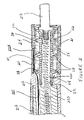
- FIG. 2 is a longitudinal cross-section of a connector terminal according to one embodiment of the present invention.
- FIG. 2 illustrates the connector terminal, for example terminal 1 shown in FIG. 1 , including a strut member 225 supporting a contact element 211 , on protrusions 28 , and supporting a seal zone element 214 , adjacent to, and approximately flush with, contact element 211 , on protrusions 26 ; protrusions 28 and 26 extend from an outer surface 24 of strut 225 while an inner surface 22 of strut 225 forms a longitudinal lumen 220 extending therethrough.
- strut 225 is formed of at least one relatively rigid and insulative material(s), examples of which include, but are not limited to, polysulfone and harder grades of polyurethanes (i.e. 75D).
- FIG. 2 further illustrates a material 21 , for example silicone medical adhesive, filling gaps between strut outer surface 24 and inner surfaces of contact element 211 and seal zone element 214 .
- materials forming seal zone element 214 include those resistant to scratching, for example by electrical contact clips (either those included within the device connector bore or those used externally, such as alligator clips), and those resistant to deformation over time under a pressure of connector bore sealing rings (i.e. sealing rings 104 illustrated in FIG. 1 ); such materials include but are not limited to harder plastics, for example polyetheretherketone (PEEK) or polysulfone, glass fiber-filled polymers and ceramics.
- PEEK polyetheretherketone
- polysulfone glass fiber-filled polymers and ceramics.
- An example of an appropriate glass fiber-filled polymer includes Elasthane 75D Polyurethane blended with Owens Corning milled glass fibers (737BC) having an average diameter of approximately 16 micrometers, a silane coating and a loading by weight ranging from approximately 2% to approximately 40%.
- Another example of a glass fiber-filled polymer includes Tecothane (TT-1075D-M, Thermedics Polymer Products, 207 Lowell Street, Wilmington, Mass. 01887) blended with chopped fiber glass (Chop Vantage 3540, PPG Industries, Inc., One PPG Place, Pittsburgh, Pa. 15272) having an average length of approximately 3.2 mm, an average diameter of approximately 10 micron, an organic sizing and a loading by weight ranging from approximately 2% to approximately 40%.
- Such composite materials are blended according to methods known to those skilled in the art, for example with a twin-screw extruder, and then molded into the form of seal zone elements.
- Ceramic materials include zirconia, alumina and sapphire. Zirconia and alumina may be molded and then machined to meet dimensional tolerances of seal zone elements, according to methods known to those skilled in the art.
- a ceramic seal zone element is joined to contact element 211 , which may be formed from titanium or gold, at adjacent edges by means of brazing; brazing processes such as are common to electrical feedthrough assembly may be employed.
- contact element 211 may be formed of any other appropriate conductive and corrosion resistant materials known to those skilled in the art, for example MP35N alloy or stainless steel.
- seal zone element 214 includes an outer surface free of protrusions, since protrusions may compromise sealing between the surface and connector bore sealing rings; protrusions which may compromise sealing are those exceeding a height of approximately 0.002 inch or 0.003 inch.
- FIG. 2 further illustrates a connector sleeve 212 coupling a lead body 215 to the connector, by means of an overlapping junction on lead body 215 and outer surface 24 of strut 225 , and a cable conductor 221 extending from lead body 215 , along strut outer surface 24 , to couple with contact element 211 .
- the illustrated embodiment also shows a coil conductor 223 extending from lead body 215 into strut lumen 220 to couple with a connector pin 213 engaged in a proximal end of strut lumen 220 .
- Conductors 221 and 223 correspond to conductors 121 and 123 shown in FIG. 1 and are formed according to any appropriate means known to those skilled in the art and from any appropriate materials known to those skilled in the art, one example of which is an MP35N alloy.
- FIG. 3A is a perspective view of a connector terminal 30 and FIG. 3B is a perspective view of a strut member 300 , included in connector terminal 30 , according to one embodiment of the present invention.
- FIG. 3A illustrates connector terminal 30 including a connector pin 37 , multiple contact elements 31 , 33 and 35 and multiple seal zone elements 32 , 34 , 36 and 38 ; such a connector terminal would support a medical electrical lead including, for example, four independent electrodes such as those employed with internal cardioversion and defibrillation devices (ICD's), which include two defibrillation electrodes and a pair of pace/sense electrodes.
- ICD's internal cardioversion and defibrillation devices
- all seal zone elements 32 , 34 , 36 and 38 are formed of one of the materials described above (for seal zone element 14 of FIG. 2 ); according to alternate embodiments, one or more of each seal zone elements 32 , 34 , 36 and 38 is formed of a different material from the rest.
- each seal zone element 32 , 34 , 36 and 38 has an outer diameter of approximately 0.126 inch and an overall length of approximately 0.113 inch; and contact elements 31 , 33 and 35 have a maximum outer diameter of approximately 0.126 inch and an exposed length of approximately 0.063 inch.
- FIG. 3B illustrates strut 300 (in the same perspective as connector 300 in FIG. 3A ), which supports contact elements 31 , 33 and 35 , on protrusions 310 , 330 and 350 , and seal zone elements 32 , 34 , 36 and 38 , on protrusions 320 , 340 , 360 and 380 ; similar to strut 225 illustrated in FIG. 2 , each protrusion 310 , 320 , 330 , 340 , 350 , 360 , and 380 extends from an outer surface of strut 300 and an inner surface of strut 300 forms a longitudinal lumen 322 extending therethrough (refer also to FIG. 6 ).
- FIG. 3A in conjunction with FIG. 3B further illustrate connector 30 including an end cap 311 which is mounted on a portion 313 of strut 300 in order to urge contact elements 31 , 33 and 35 and seal zone elements 32 , 34 , 36 and 38 against one another and against a stop 325 formed at an opposite of strut 300 ; portion 313 includes locking recesses 71 and 72 to fixedly engage an inner surface of cap 311 , which will be described in greater detail in conjunction with FIGS. 7F and 8 .
- FIG. 3B also illustrates a surface 315 at a distal end of strut, onto which a generally tubular lead body 615 ( FIG. 6 ) may be mounted
- FIG. 3A illustrates a connector sleeve 302 , which overlays lead body 615 and end cap 311 ( FIG. 6 ).
- FIG. 3B further illustrates a first conductor channel 75 extending along an outer surface of strut 300 , cutting through protrusions 310 , 320 , 330 , 340 , 350 and 360 .
- FIG. 4 is a perspective view of the connector terminal shown in FIG. 3A wherein only contact elements 31 , 33 and 35 and their associated conductors 51 , 53 and 55 , respectively, are shown to illustrate a routing of conductors 51 , 53 and 55 along the outer surface of strut 300 .
- first channel 75 extends through protrusions 310 , 320 , 330 , 340 , 350 and 360 holding conductor 55
- a second channel extends at least through protrusions 310 , 320 , 330 and 340 to hold conductor 53
- a third channel extends at least through protrusions 310 and 320 to hold conductor 51 ; the channels are positioned spaced apart from one another, about a circumference of the strut, to isolate conductors 51 , 53 and 55 from one another.
- cable conductors 51 , 53 and 55 are coupled to contact elements 31 , 33 , and 35 within a feature formed on an internal surface of contact elements 31 , 33 , and 35 ;
- FIGS. 5A–B illustrate such an embodiment.
- FIG. 5A is a plan view of the subassembly of contact element 31 and conductor 51 and
- FIG. 5B is an end view of contact element 31 .
- FIG. 5A is a plan view of the subassembly of contact element 31 and conductor 51
- FIG. 5B is an end view of contact element 31 .
- outer insulative layer 511 illustrates conductor 51 including an outer insulative layer 511 which is stripped from an end 512 of conductor 51 ; end 512 is inserted into an eyelet 41 , formed in sidewall 40 of contact element 31 , and force directed, per arrow A, from an lumen 42 of contact element 31 crimps end 512 within eyelet 41 to electrically and mechanically couple conductor 51 to contact element 31 .
- outer insulative layer 511 is a fluoropolymer coating, for example PTFE or ETFE.
- FIG. 3B further illustrates strut 300 including a backfill channel 317 extending from surface 315 , along strut outer surface, to an end point 39 in proximity to the proximal end of strut 300 .
- channel 317 provides a guide for a needle to enter beneath seal zone elements 32 , 34 , 36 and 38 and contact elements 31 , 33 and 35 in order to dispense a backfill material between these elements and the outer surface of strut 300 .
- FIG. 6 illustrates the connector including a backfill 621 and such a filling method will be described in greater detail in conjunction with FIG. 7E .
- FIG. 6 is a longitudinal cross-section of a portion of the connector terminal shown in FIG. 3A .
- FIG. 6 illustrates each contact element 31 , 33 and 35 including recessed outer surfaces extending from each end, for example surfaces 43 of contact element 33 , so that a portion of an inner surface of each seal zone element 32 , 34 , 36 and 38 may overlap, for example inner surface 634 or seal zone element 34 and inner surface 636 of seal zone element 36 ; according to this embodiment of the present invention overlapping surfaces facilitate stable positioning of outer surfaces of seal zone elements 32 , 34 , 36 and 38 and contact elements 31 , 33 and 35 flush with one another.
- seal zone inner surfaces 632 , 634 and 636 further include a surface treatment promoting adhesion with backfill material 621 ;
- backfill material 621 is silicone medical adhesive and inner surfaces 632 , 634 and 636 of seal zone elements 32 , 34 , and 36 , formed of either a ceramic or a polysulfone undergo a siloxane plasma treatment.
- seal zone elements 32 , 34 , and 36 are hot heptane cleaned to enhance adhesion, and according to yet another ceramic embodiment, a forming operation for elements 32 , 34 , and 36 includes a clean fire step to enhance adhesion.
- outer insulative layers of conductors are treated for adhesion with backfill 621 , for example layers 511 and 551 (of conductors 51 and 55 ), formed of a fluoropolymer, include a silane plasma treatment to enhance bonding with silicone medical adhesive as backfill 621 .
- FIG. 6 illustrates an inner surface of a lumen 616 of lead body 615 mounted on mounting surface 315 ( FIG. 3B ) of strut; strut end cap 311 extends over lead body 615 and connector sleeve 302 , which is coupled to an outer surface of lead body 615 , extends over end cap 311 such that a proximal edge 62 interlocks in a groove 61 of end cap 311 .
- end cap is formed of a rigid plastic, for example of a relatively hard grade of polyurethane or of a polysulfone
- sleeve 302 and lead body are formed of a more flexible polymer, for example of a softer grade of polyurethane or of silicone.
- lead body 615 and strut mounting surface 315 , sleeve 302 and lead body 615 , sleeve 302 and end cap 311 and end cap 311 and strut portion 313 may be joined by any appropriate means known to those skilled in the art, for example adhesively bonded or ultrasonically welded.
- FIG. 6 further illustrates lumen 322 of strut 300 including a proximal portion 60 , which according to one embodiment is enlarged to engage connector pin 37 and a pin retaining element 370 (both shown by dashed lines), which is bonded within strut 300 to hold pin 37 in place; as in FIG. 2 , a conductor 623 extends from lead body 615 through lumen 322 to couple with pin 37 .
- FIG. 6 also illustrates a keying feature 65 formed in lumen 322 in proximity to portion 60 ; according to one embodiment, keying feature 65 is used to orient strut 300 on an assembly pin 700 ( FIG. 7A ), which facilitates proper assembly of the connector terminal as will be described in conjunction with FIGS. 7A–F .
- FIGS. 7A–E are plan views of a connector subassembly at successive stages of an assembly process according to one method of the present invention
- FIG. 7F is a perspective end view of the connector subassembly shown in FIG. 7E according to one embodiment of the present invention.
- FIG. 7A illustrates strut 300 mounted on assembly pin 700
- FIG. 7B illustrates seal zone element 38 and contact element 35 , which is coupled to conductor 55 , having been mounted, successively or jointly, onto strut per arrow A.
- Conductor 55 may have been coupled to contact element 35 prior to assembly on strut 300 , as previously described in conjunction with FIGS.
- conductor 55 may have been coupled according to other means known to those skilled in the art, such as laser welding, either before assembly of contact element 35 onto strut or after assembly of contact element 35 onto strut; such is the case for each contact element assembled onto strut 300 .
- strut 300 is molded from a relatively rigid and insulative material, for example 75D polyurethane or polysulfone.
- protrusion 380 supports seal zone element 38
- protrusions 350 support contact element 35
- channel 75 allows passage of conductor 55 along the outer surface of strut 300 , distally from contact element 35 .
- a bead of adhesive may be dispensed on an inner surface of element 38 or on a surface of protrusion 380 .
- FIG. 7C illustrates seal zone element 36 and contact element 33 , which is coupled to conductor 53 , having been mounted, successively or jointly, onto strut per arrow A ( FIG. 7B ).
- protrusion 360 supports seal zone element 36
- protrusions 330 support contact element 33 and a channel on another side (not seen) of strut allows passage of conductor 53 along the outer surface of strut 300 , distally from contact element 33 .
- FIG. 7D illustrates seal zone element 34 and contact element 31 , which is coupled to conductor 51 , having been mounted, successively or jointly, onto strut 300 per arrow A ( FIG. 7B ).
- protrusion 340 supports seal zone element 34
- protrusions 310 support contact element 31 and a channel (not seen) along a side of strut allows passage of conductor 51 along the outer surface of strut 300 , distally from contact element 31 .
- FIG. 7E illustrates seal zone element 32 and end cap 311 having been mounted onto strut per arrow A ( FIG. 7B ).
- protrusion 320 supports seal zone element 32 and strut portion 313 supports end cap 311 .
- FIG. 7F is a perspective end view of the connector subassembly shown in FIG. 7E wherein locking recesses 71 and 72 engage internal protruding features 710 and 720 , respectively, of cap 311 .
- cap 311 is mounted onto strut 300 by first sliding cap 311 over portion 313 , per arrow A, so that internal protruding features 710 and 720 are longitudinally aligned with locking recesses 71 and 72 but circumferentially offset from recesses 71 and 72 , as illustrated in FIG. 8 . Then, to engage protruding features 710 and 720 in locking recesses 71 and 72 , cap 311 is rotated, per arrow C ( FIG. 8 ) until protruding features 710 and 720 ‘bottom out’ circumferentially in locking recesses 71 and 72 , at which point cap 311 is pushed per arrow A ( FIG.
- recesses 71 and 72 are dimensioned to provide some play allowing variances in length due to a tolerance stack up of seal zone elements 32 , 34 , 36 and 38 and contact elements 31 , 33 , and 35 on strut 300 .
- adhesive may be applied in locking recesses 71 and 72 .
- FIGS. 7E and 7F further illustrate an assembly backfilling method according to one embodiment wherein a needle attached to a syringe filled with backfill material (not shown) is inserted, per arrow B, in between strut 300 and assembled seal zone elements 32 , 34 , 36 and 38 , contact elements 31 , 33 , and 35 and end cap 311 , along channel 317 (also shown in FIG. 3B ).
- the needle is inserted such that a tip of the needle bottoms out against end point 39 ( FIG. 3B ) and is slowly withdrawn as backfill material 621 ( FIG. 6 ) is dispensed; as illustrated in FIG. 7E , end cap 311 further includes a vent hole 77 facilitating release of air for a uniform fill.
- an EFD HP-4X dispenser incorporating an XL1000 dispense valve and a 23 gauge thin-walled needle, approximately 0.925 inches long (equipment commercially available from EFD Inc. of East Buffalo Rhode Island) is used to dispense silicone medical adhesive at a dispensing pressure of approximately 70 psi.
- adjacent edges of seal zone elements 32 , 34 , 36 and 38 and contact elements 31 , 33 , and 35 are further joined together, for example by brazing, as previously described, or by adhesive bonding.
- final assembly steps encompass joining a lead body, i.e. body 615 shown in FIG. 6 .
- conductor coil 623 extending proximally from lead body 615 is routed into lumen 322 of strut 300 and lead body lumen 616 is mounted on mounting surface 315 ; according to this embodiment, coil 623 may be stretched proximally out from strut proximal portion 60 to couple coil 623 to connector pin 37 , for example, via welding or crimping, after which pin 37 is pushed into proximal portion 60 and secured there by means of retaining element 370 as previously described.
- cable conductors 51 , 53 and 55 FIG.
- conductors 51 , 53 and 55 are of a shorter length and are thus each spliced, in proximity of connector sleeve 302 , to conductors extending proximally through lead body 615 from lead electrodes in the subsequent steps of lead assembly.
Abstract
Description
Claims (89)
Priority Applications (1)
| Application Number | Priority Date | Filing Date | Title |
|---|---|---|---|
| US10/812,796 US7108549B2 (en) | 2004-03-30 | 2004-03-30 | Medical electrical connector |
Applications Claiming Priority (1)
| Application Number | Priority Date | Filing Date | Title |
|---|---|---|---|
| US10/812,796 US7108549B2 (en) | 2004-03-30 | 2004-03-30 | Medical electrical connector |
Publications (2)
| Publication Number | Publication Date |
|---|---|
| US20050221671A1 US20050221671A1 (en) | 2005-10-06 |
| US7108549B2 true US7108549B2 (en) | 2006-09-19 |
Family
ID=35054968
Family Applications (1)
| Application Number | Title | Priority Date | Filing Date |
|---|---|---|---|
| US10/812,796 Expired - Lifetime US7108549B2 (en) | 2004-03-30 | 2004-03-30 | Medical electrical connector |
Country Status (1)
| Country | Link |
|---|---|
| US (1) | US7108549B2 (en) |
Cited By (50)
| Publication number | Priority date | Publication date | Assignee | Title |
|---|---|---|---|---|
| US7241180B1 (en) * | 2006-01-31 | 2007-07-10 | Medtronic, Inc. | Medical electrical lead connector assembly |
| US7364479B1 (en) * | 2007-02-02 | 2008-04-29 | Pacesetter, Inc. | Crimp connector for connecting a conductor cable and electrode of an implantable cardiac electrotherapy lead |
| US20080208279A1 (en) * | 2007-01-18 | 2008-08-28 | Medtronic, Inc. | Internal hermetic lead connector for implantable device |
| US20080246231A1 (en) * | 2007-04-09 | 2008-10-09 | Sjostedt Robbie J | Connector assembly for use with medical devices |
| US20080254670A1 (en) * | 2007-04-13 | 2008-10-16 | Balsells Peter J | Electrical connectors with improved electrical contact performance |
| US20080255631A1 (en) * | 2007-04-11 | 2008-10-16 | Sjostedt Robbie J | Integrated header connector system |
| US20090149053A1 (en) * | 2007-12-06 | 2009-06-11 | Changsrivong Derek | In-line connector |
| US20090198312A1 (en) * | 2008-01-31 | 2009-08-06 | John Michael Barker | Lead with lead stiffener for implantable electrical stimulation systems and methods of making and using |
| US20090258519A1 (en) * | 2008-04-11 | 2009-10-15 | Farshid Dilmaghanian | Connector cartridge stack for electrical transmission |
| US20100029145A1 (en) * | 2008-07-30 | 2010-02-04 | Pete Balsells | Canted coil multi-metallic wire |
| US20100233896A1 (en) * | 2009-03-11 | 2010-09-16 | Farshid Dilmaghanian | Header assembly for implantable medical devices |
| US20100273355A1 (en) * | 2009-04-22 | 2010-10-28 | Tyco Electronics Corporation | Image guide wire connection |
| US20100269339A1 (en) * | 2009-04-24 | 2010-10-28 | Advanced Neuromodulation Systems, Inc. | Method of fabricating stimulation lead by fusing connector segment between lead body and electrode portion of the lead |
| US20100289198A1 (en) * | 2009-04-28 | 2010-11-18 | Pete Balsells | Multilayered canted coil springs and associated methods |
| US20110022102A1 (en) * | 2007-08-15 | 2011-01-27 | Gerry Rey | Connector assembly for use with medical devices |
| US20120151765A1 (en) * | 2010-12-21 | 2012-06-21 | Pacesetter, Inc. | Lead connector end with integrated shunt |
| WO2012128777A1 (en) | 2011-03-18 | 2012-09-27 | Medtronic, Inc. | In-line connector terminals for implantable medical electrical leads |
| US20120277838A1 (en) * | 2009-07-13 | 2012-11-01 | Boston Scientific Neuromodulation Corporation | Method for fabricating a neurostimulation lead contact array |
| US8328587B2 (en) | 2009-04-20 | 2012-12-11 | Bal Seal Engineering, Inc. | In-line connector stack with testing capability |
| US20120315798A1 (en) * | 2011-06-09 | 2012-12-13 | Bal Seal Engineering, Inc. | Method, apparatus and system for positioning and holding electrical contacts, seals and related components |
| US20120322318A1 (en) * | 2011-03-16 | 2012-12-20 | SORIN CRM SAS Parc d'affairs NOVEOS | Electrical Connection Plug For A Multipolar Lead Of Active Implantable Medical Device |
| US8639358B2 (en) | 2012-01-13 | 2014-01-28 | Medtronic, Inc | Fail-safe implantable medical electrical lead |
| US20150011107A1 (en) * | 2013-07-02 | 2015-01-08 | Northrop Grumman Systems Corporation | Wet-mateable electrical connector with wet contacts and an associated method |
| US9072909B1 (en) | 2013-12-18 | 2015-07-07 | Medtronic, Inc. | Implantable medical electrical lead connectors, assemblies thereof, and methods of manufacture |
| US9106004B2 (en) | 2013-12-19 | 2015-08-11 | Medtronic, Inc. | Implantable medical electrical leads and connector assemblies thereof |
| US9101776B2 (en) | 2013-12-18 | 2015-08-11 | Medtronic, Inc. | Implantable medical electrical lead connector assemblies and methods of manufacture |
| US9138576B2 (en) | 2011-10-28 | 2015-09-22 | Medtronic, Inc. | Lead end having inner support |
| US9421362B2 (en) | 2011-10-28 | 2016-08-23 | Medtronic, Inc. | Modular lead end |
| US20170014635A1 (en) * | 2015-07-16 | 2017-01-19 | Boston Scientific Neuromodulation Corporation | Systems and methods for making and using connector contact arrays for electrical stimulation systems |
| US9855419B2 (en) | 2009-05-29 | 2018-01-02 | Medtronic, Inc. | Leads for selective sensing and virtual electrodes |
| US9956394B2 (en) | 2015-09-10 | 2018-05-01 | Boston Scientific Neuromodulation Corporation | Connectors for electrical stimulation systems and methods of making and using |
| US10076657B2 (en) | 2011-10-28 | 2018-09-18 | Medtronic, Inc. | Lead end having slotted member |
| US10201713B2 (en) | 2016-06-20 | 2019-02-12 | Boston Scientific Neuromodulation Corporation | Threaded connector assembly and methods of making and using the same |
| US10307602B2 (en) | 2016-07-08 | 2019-06-04 | Boston Scientific Neuromodulation Corporation | Threaded connector assembly and methods of making and using the same |
| US10342983B2 (en) | 2016-01-14 | 2019-07-09 | Boston Scientific Neuromodulation Corporation | Systems and methods for making and using connector contact arrays for electrical stimulation systems |
| US10543374B2 (en) | 2016-09-30 | 2020-01-28 | Boston Scientific Neuromodulation Corporation | Connector assemblies with bending limiters for electrical stimulation systems and methods of making and using same |
| US10576269B2 (en) | 2017-01-03 | 2020-03-03 | Boston Scientific Neuromodulation Corporation | Force-decoupled and strain relieving lead and methods of making and using |
| US10603499B2 (en) | 2017-04-07 | 2020-03-31 | Boston Scientific Neuromodulation Corporation | Tapered implantable lead and connector interface and methods of making and using |
| US10639485B2 (en) | 2017-09-15 | 2020-05-05 | Boston Scientific Neuromodulation Corporation | Actuatable lead connector for an operating room cable assembly and methods of making and using |
| US10765858B2 (en) | 2014-11-05 | 2020-09-08 | Medtronic, Inc. | Extravascular lead designs for optimized pacing and sensing having segmented, partially electrically insulated defibrillation coils |
| US10814136B2 (en) | 2017-02-28 | 2020-10-27 | Boston Scientific Neuromodulation Corporation | Toolless connector for latching stimulation leads and methods of making and using |
| US10905871B2 (en) | 2017-01-27 | 2021-02-02 | Boston Scientific Neuromodulation Corporation | Lead assemblies with arrangements to confirm alignment between terminals and contacts |
| US10918873B2 (en) | 2017-07-25 | 2021-02-16 | Boston Scientific Neuromodulation Corporation | Systems and methods for making and using an enhanced connector of an electrical stimulation system |
| US11045656B2 (en) | 2017-09-15 | 2021-06-29 | Boston Scientific Neuromodulation Corporation | Biased lead connector for operating room cable assembly and methods of making and using |
| US11052259B2 (en) | 2018-05-11 | 2021-07-06 | Boston Scientific Neuromodulation Corporation | Connector assembly for an electrical stimulation system and methods of making and using |
| US11103712B2 (en) | 2018-01-16 | 2021-08-31 | Boston Scientific Neuromodulation Corporation | Connector assemblies with novel spacers for electrical stimulation systems and methods of making and using same |
| US11139603B2 (en) | 2017-10-03 | 2021-10-05 | Boston Scientific Neuromodulation Corporation | Connectors with spring contacts for electrical stimulation systems and methods of making and using same |
| US11167128B2 (en) | 2018-11-16 | 2021-11-09 | Boston Scientific Neuromodulation Corporation | Directional electrical stimulation leads, systems and methods for spinal cord stimulation |
| US11172959B2 (en) | 2018-05-02 | 2021-11-16 | Boston Scientific Neuromodulation Corporation | Long, flexible sheath and lead blank and systems and methods of making and using |
| US11357992B2 (en) | 2019-05-03 | 2022-06-14 | Boston Scientific Neuromodulation Corporation | Connector assembly for an electrical stimulation system and methods of making and using |
Families Citing this family (14)
| Publication number | Priority date | Publication date | Assignee | Title |
|---|---|---|---|---|
| US7191017B1 (en) * | 2004-07-09 | 2007-03-13 | Cardiac Pacemakers Inc. | Two-part implantable cardiac lead |
| US7326083B2 (en) * | 2005-12-29 | 2008-02-05 | Medtronic, Inc. | Modular assembly of medical electrical leads |
| US20080077050A1 (en) * | 2006-09-08 | 2008-03-27 | Radi Medical Systems Ab | Electrical connector for medical device |
| EP1897582A1 (en) * | 2006-09-08 | 2008-03-12 | Radi Medical Systems Ab | Male connector for a guide wire mounted sensor |
| DE102007006089A1 (en) | 2007-02-07 | 2008-08-14 | Biotronik Crm Patent Ag | Electrode lead and connector for an implantable cardiac stimulator |
| US8027739B2 (en) * | 2007-09-13 | 2011-09-27 | Cardiac Pacemakers, Inc. | Medical device having a glass coating and method therefor |
| DE102008008927A1 (en) | 2008-02-13 | 2009-08-20 | Biotronik Crm Patent Ag | Electrode lead and fitting for electromedical implants |
| US9240117B2 (en) * | 2010-12-15 | 2016-01-19 | Medtronic, Inc. | Medical lead insertion detection by monitoring for electrical continuity between adjacent electrical contacts of a medical device |
| US9079037B2 (en) | 2012-04-27 | 2015-07-14 | Medtronic, Inc. | Fault tolerant implantable medical system |
| US8996111B2 (en) | 2012-04-27 | 2015-03-31 | Medtronic, Inc. | Lead recognition for an implantable medical system |
| US10034705B2 (en) * | 2013-10-24 | 2018-07-31 | St. Jude Medical, Cardiology Division, Inc. | High strength electrode assembly for catheter system including novel electrode |
| DE102015121815A1 (en) * | 2015-12-15 | 2017-06-22 | Biotronik Se & Co. Kg | Implantable electrode lead and set of electrode lead modules |
| GB201522289D0 (en) * | 2015-12-17 | 2016-02-03 | Strip Tinning Ltd | Electrical connection |
| DE102019127686A1 (en) * | 2019-10-15 | 2021-04-15 | Türk & Hillinger GmbH | Bushing for an electrical heating device, electrical heating device with such a bushing, system with such a bushing and method for producing such a bushing |
Citations (10)
| Publication number | Priority date | Publication date | Assignee | Title |
|---|---|---|---|---|
| US4898173A (en) | 1988-04-22 | 1990-02-06 | Medtronic, Inc. | In-line pacemaker connector system |
| US4922607A (en) | 1988-05-25 | 1990-05-08 | Medtronic, Inc. | Method of fabrication an in-line, multipolar electrical connector |
| US4944088A (en) | 1988-05-25 | 1990-07-31 | Medtronic, Inc. | Ring electrode for multiconductor pacing leads |
| US5007435A (en) | 1988-05-25 | 1991-04-16 | Medtronic, Inc. | Connector for multiconductor pacing leads |
| US5843141A (en) * | 1997-04-25 | 1998-12-01 | Medronic, Inc. | Medical lead connector system |
| US6026567A (en) | 1995-05-11 | 2000-02-22 | Medtronic, Inc. | Medical lead with stranded conductors |
| US6167314A (en) * | 1998-04-14 | 2000-12-26 | Intermedics Inc. | Cardiac pacemaker lead with pacemaker connector |
| US6244882B1 (en) * | 1995-11-21 | 2001-06-12 | Agilent Technologies, Inc. | Medical connector apparatus |
| US6501990B1 (en) | 1999-12-23 | 2002-12-31 | Cardiac Pacemakers, Inc. | Extendable and retractable lead having a snap-fit terminal connector |
| US20030163171A1 (en) | 2002-02-28 | 2003-08-28 | Kast John E. | In-line lead header for an implantable medical device |
-
2004
- 2004-03-30 US US10/812,796 patent/US7108549B2/en not_active Expired - Lifetime
Patent Citations (11)
| Publication number | Priority date | Publication date | Assignee | Title |
|---|---|---|---|---|
| US4898173A (en) | 1988-04-22 | 1990-02-06 | Medtronic, Inc. | In-line pacemaker connector system |
| US4922607A (en) | 1988-05-25 | 1990-05-08 | Medtronic, Inc. | Method of fabrication an in-line, multipolar electrical connector |
| US4944088A (en) | 1988-05-25 | 1990-07-31 | Medtronic, Inc. | Ring electrode for multiconductor pacing leads |
| US5007435A (en) | 1988-05-25 | 1991-04-16 | Medtronic, Inc. | Connector for multiconductor pacing leads |
| US6026567A (en) | 1995-05-11 | 2000-02-22 | Medtronic, Inc. | Medical lead with stranded conductors |
| US6244882B1 (en) * | 1995-11-21 | 2001-06-12 | Agilent Technologies, Inc. | Medical connector apparatus |
| US5843141A (en) * | 1997-04-25 | 1998-12-01 | Medronic, Inc. | Medical lead connector system |
| US6167314A (en) * | 1998-04-14 | 2000-12-26 | Intermedics Inc. | Cardiac pacemaker lead with pacemaker connector |
| US6501990B1 (en) | 1999-12-23 | 2002-12-31 | Cardiac Pacemakers, Inc. | Extendable and retractable lead having a snap-fit terminal connector |
| US20030163171A1 (en) | 2002-02-28 | 2003-08-28 | Kast John E. | In-line lead header for an implantable medical device |
| US6895276B2 (en) * | 2002-02-28 | 2005-05-17 | Medtronic, Inc. | In-line lead header for an implantable medical device |
Non-Patent Citations (4)
| Title |
|---|
| "Active Implantable Medical Devices-Four-Pole Connector System for Implantable Cardiac Rhythm Management Devices," PAC/CTF-N151R5 WD, p. i-58, AAMI (2000). |
| Belden, L., Memo, "Medtronic Quadripolar IS-4 Proposal," Association for the Advancement of Medical Instrumentation, Pacemaker Committee, Connector Task Force-IS-4 Team, PAC/CTF-N135, p. 1-6 (Sep. 18, 2000). |
| Meeting minutes, Association for the Advancement of Medical Instrumentation, Pacemaker Committee, Connector Task Force-IS-4 Team Teleconference, PAC/CTF-N137, p. 1-2 (Sep. 21, 2000). |
| Meeting minutes, Association for the Advancement of Medical Instrumentation, Pacemaker Committee, Connector Task Force-IS-4 Team Teleconference, PAC/CTF-N152, p. 1-2 (Nov. 30, 2000). |
Cited By (82)
| Publication number | Priority date | Publication date | Assignee | Title |
|---|---|---|---|---|
| US20070178770A1 (en) * | 2006-01-31 | 2007-08-02 | Douglas Rentas Torres | Medical electrical lead connector assembly |
| US7241180B1 (en) * | 2006-01-31 | 2007-07-10 | Medtronic, Inc. | Medical electrical lead connector assembly |
| US7720538B2 (en) * | 2007-01-18 | 2010-05-18 | Medtronic, Inc. | Internal hermetic lead connector for implantable device |
| US20080208279A1 (en) * | 2007-01-18 | 2008-08-28 | Medtronic, Inc. | Internal hermetic lead connector for implantable device |
| US7364479B1 (en) * | 2007-02-02 | 2008-04-29 | Pacesetter, Inc. | Crimp connector for connecting a conductor cable and electrode of an implantable cardiac electrotherapy lead |
| US20080246231A1 (en) * | 2007-04-09 | 2008-10-09 | Sjostedt Robbie J | Connector assembly for use with medical devices |
| US8437855B2 (en) | 2007-04-09 | 2013-05-07 | Bal Seal Engineering, Inc. | Connector assembly for use with medical devices |
| US20080255631A1 (en) * | 2007-04-11 | 2008-10-16 | Sjostedt Robbie J | Integrated header connector system |
| US8091226B2 (en) | 2007-04-11 | 2012-01-10 | Bal Seal Engineering, Inc. | Integrated header connector system |
| US20080254670A1 (en) * | 2007-04-13 | 2008-10-16 | Balsells Peter J | Electrical connectors with improved electrical contact performance |
| US7914351B2 (en) | 2007-04-13 | 2011-03-29 | Bal Seal Engineering | Electrical connectors with improved electrical contact performance |
| US20110022102A1 (en) * | 2007-08-15 | 2011-01-27 | Gerry Rey | Connector assembly for use with medical devices |
| US7890175B1 (en) | 2007-08-15 | 2011-02-15 | Bal Seal Engineering, Inc. | Connector assembly for use with medical devices |
| US7955145B2 (en) | 2007-12-06 | 2011-06-07 | Bal Seal Engineering, Inc. | In-line connector |
| US20100199493A1 (en) * | 2007-12-06 | 2010-08-12 | Derek Chansrivong | In-line connector |
| US7722415B2 (en) | 2007-12-06 | 2010-05-25 | Bal Seal Engineering, Inc. | In-line connector |
| US20090149053A1 (en) * | 2007-12-06 | 2009-06-11 | Changsrivong Derek | In-line connector |
| US8391982B2 (en) * | 2008-01-31 | 2013-03-05 | Boston Scientific Neuromodulation Corporation | Lead with lead stiffener for implantable electrical stimulation systems and methods of making and using |
| US8712528B2 (en) | 2008-01-31 | 2014-04-29 | Boston Scientific Neuromodulation Corporation | Lead with lead stiffener for implantable electrical stimulation systems and methods of making and using |
| US20090198312A1 (en) * | 2008-01-31 | 2009-08-06 | John Michael Barker | Lead with lead stiffener for implantable electrical stimulation systems and methods of making and using |
| US8480437B2 (en) | 2008-04-11 | 2013-07-09 | Bal Seal Engineering, Inc. | Connector cartridge stack for electrical transmission |
| US20090258519A1 (en) * | 2008-04-11 | 2009-10-15 | Farshid Dilmaghanian | Connector cartridge stack for electrical transmission |
| US8215013B2 (en) | 2008-04-11 | 2012-07-10 | Bal Seal Engineering, Inc. | Method for making a free standing axially compressed connector stack |
| US9293849B2 (en) | 2008-07-30 | 2016-03-22 | Bal Seal Engineering, Inc. | Electrical connector using a canted coil multi-metallic wire |
| US20100029145A1 (en) * | 2008-07-30 | 2010-02-04 | Pete Balsells | Canted coil multi-metallic wire |
| US8096838B2 (en) | 2009-03-11 | 2012-01-17 | Bal Seal Engineering, Inc. | Header assembly for implantable medical devices |
| US20100233896A1 (en) * | 2009-03-11 | 2010-09-16 | Farshid Dilmaghanian | Header assembly for implantable medical devices |
| US8328587B2 (en) | 2009-04-20 | 2012-12-11 | Bal Seal Engineering, Inc. | In-line connector stack with testing capability |
| US20100273355A1 (en) * | 2009-04-22 | 2010-10-28 | Tyco Electronics Corporation | Image guide wire connection |
| US8342887B2 (en) | 2009-04-22 | 2013-01-01 | Tyco Electronics Corporation | Image guide wire connection |
| US8046909B2 (en) * | 2009-04-24 | 2011-11-01 | Advanced Neuromodulation Systems, Inc. | Method of fabricating stimulation lead |
| US20100269339A1 (en) * | 2009-04-24 | 2010-10-28 | Advanced Neuromodulation Systems, Inc. | Method of fabricating stimulation lead by fusing connector segment between lead body and electrode portion of the lead |
| US20100289198A1 (en) * | 2009-04-28 | 2010-11-18 | Pete Balsells | Multilayered canted coil springs and associated methods |
| US9855419B2 (en) | 2009-05-29 | 2018-01-02 | Medtronic, Inc. | Leads for selective sensing and virtual electrodes |
| US8694124B2 (en) * | 2009-07-13 | 2014-04-08 | Boston Scientific Neuromodulation Corporation | Method for fabricating a neurostimulation lead contact array |
| US20120277838A1 (en) * | 2009-07-13 | 2012-11-01 | Boston Scientific Neuromodulation Corporation | Method for fabricating a neurostimulation lead contact array |
| US20120151765A1 (en) * | 2010-12-21 | 2012-06-21 | Pacesetter, Inc. | Lead connector end with integrated shunt |
| US9227049B2 (en) | 2011-03-16 | 2016-01-05 | Sorin Crm S.A.S. | Method of manufacturing electrical connection plug for a multipolar lead of an active implantable medical device |
| US20120322318A1 (en) * | 2011-03-16 | 2012-12-20 | SORIN CRM SAS Parc d'affairs NOVEOS | Electrical Connection Plug For A Multipolar Lead Of Active Implantable Medical Device |
| US8641436B2 (en) * | 2011-03-16 | 2014-02-04 | Sorin Crm S.A.S. | Electrical plug having a plurality of housings with PODS welded to a plurality of wires and conductive rings |
| US8567055B2 (en) | 2011-03-18 | 2013-10-29 | Medtronic, Inc. | Method of assembling an in-line connector terminal |
| WO2012128777A1 (en) | 2011-03-18 | 2012-09-27 | Medtronic, Inc. | In-line connector terminals for implantable medical electrical leads |
| US8690609B2 (en) * | 2011-06-09 | 2014-04-08 | Bal Seal Engineering, Inc. | Method, apparatus and system for positioning and holding electrical contacts, seals and related components |
| US20120315798A1 (en) * | 2011-06-09 | 2012-12-13 | Bal Seal Engineering, Inc. | Method, apparatus and system for positioning and holding electrical contacts, seals and related components |
| US9713705B2 (en) * | 2011-10-28 | 2017-07-25 | Medtronic, Inc. | Modular lead end |
| US10413718B2 (en) | 2011-10-28 | 2019-09-17 | Medtronic, Inc. | Modular lead end |
| US9138576B2 (en) | 2011-10-28 | 2015-09-22 | Medtronic, Inc. | Lead end having inner support |
| US10076657B2 (en) | 2011-10-28 | 2018-09-18 | Medtronic, Inc. | Lead end having slotted member |
| US20180236219A1 (en) * | 2011-10-28 | 2018-08-23 | Medtronic, Inc. | Modular lead end |
| US9962539B2 (en) | 2011-10-28 | 2018-05-08 | Medtronic, Inc. | Modular lead end |
| US9421362B2 (en) | 2011-10-28 | 2016-08-23 | Medtronic, Inc. | Modular lead end |
| US8639358B2 (en) | 2012-01-13 | 2014-01-28 | Medtronic, Inc | Fail-safe implantable medical electrical lead |
| US20150011107A1 (en) * | 2013-07-02 | 2015-01-08 | Northrop Grumman Systems Corporation | Wet-mateable electrical connector with wet contacts and an associated method |
| US9197006B2 (en) * | 2013-07-02 | 2015-11-24 | Northrop Grumman Systems Corporation | Electrical connector having male and female contacts in contact with a fluid in fully mated condition |
| US9101776B2 (en) | 2013-12-18 | 2015-08-11 | Medtronic, Inc. | Implantable medical electrical lead connector assemblies and methods of manufacture |
| US9072909B1 (en) | 2013-12-18 | 2015-07-07 | Medtronic, Inc. | Implantable medical electrical lead connectors, assemblies thereof, and methods of manufacture |
| US9106004B2 (en) | 2013-12-19 | 2015-08-11 | Medtronic, Inc. | Implantable medical electrical leads and connector assemblies thereof |
| US10765858B2 (en) | 2014-11-05 | 2020-09-08 | Medtronic, Inc. | Extravascular lead designs for optimized pacing and sensing having segmented, partially electrically insulated defibrillation coils |
| US9656093B2 (en) * | 2015-07-16 | 2017-05-23 | Boston Scientific Neuromodulation Corporation | Systems and methods for making and using connector contact arrays for electrical stimulation systems |
| US20170014635A1 (en) * | 2015-07-16 | 2017-01-19 | Boston Scientific Neuromodulation Corporation | Systems and methods for making and using connector contact arrays for electrical stimulation systems |
| US20170216604A1 (en) * | 2015-07-16 | 2017-08-03 | Boston Scientific Neuromodulation Corporation | Systems and methods for making and using connector contact arrays for electrical stimulation systems |
| US9839787B2 (en) * | 2015-07-16 | 2017-12-12 | Boston Scientific Neuromodulation Corporation | Systems and methods for making and using connector contact arrays for electrical stimulation systems |
| US9956394B2 (en) | 2015-09-10 | 2018-05-01 | Boston Scientific Neuromodulation Corporation | Connectors for electrical stimulation systems and methods of making and using |
| US10342983B2 (en) | 2016-01-14 | 2019-07-09 | Boston Scientific Neuromodulation Corporation | Systems and methods for making and using connector contact arrays for electrical stimulation systems |
| US10201713B2 (en) | 2016-06-20 | 2019-02-12 | Boston Scientific Neuromodulation Corporation | Threaded connector assembly and methods of making and using the same |
| US10307602B2 (en) | 2016-07-08 | 2019-06-04 | Boston Scientific Neuromodulation Corporation | Threaded connector assembly and methods of making and using the same |
| US10543374B2 (en) | 2016-09-30 | 2020-01-28 | Boston Scientific Neuromodulation Corporation | Connector assemblies with bending limiters for electrical stimulation systems and methods of making and using same |
| US10576269B2 (en) | 2017-01-03 | 2020-03-03 | Boston Scientific Neuromodulation Corporation | Force-decoupled and strain relieving lead and methods of making and using |
| US10905871B2 (en) | 2017-01-27 | 2021-02-02 | Boston Scientific Neuromodulation Corporation | Lead assemblies with arrangements to confirm alignment between terminals and contacts |
| US10814136B2 (en) | 2017-02-28 | 2020-10-27 | Boston Scientific Neuromodulation Corporation | Toolless connector for latching stimulation leads and methods of making and using |
| US10603499B2 (en) | 2017-04-07 | 2020-03-31 | Boston Scientific Neuromodulation Corporation | Tapered implantable lead and connector interface and methods of making and using |
| US10918873B2 (en) | 2017-07-25 | 2021-02-16 | Boston Scientific Neuromodulation Corporation | Systems and methods for making and using an enhanced connector of an electrical stimulation system |
| US10639485B2 (en) | 2017-09-15 | 2020-05-05 | Boston Scientific Neuromodulation Corporation | Actuatable lead connector for an operating room cable assembly and methods of making and using |
| US11045656B2 (en) | 2017-09-15 | 2021-06-29 | Boston Scientific Neuromodulation Corporation | Biased lead connector for operating room cable assembly and methods of making and using |
| US11951317B2 (en) | 2017-09-15 | 2024-04-09 | Boston Scientific Neuromodulation Corporation | Biased lead connector for operating room cable assembly and methods of making and using |
| US11139603B2 (en) | 2017-10-03 | 2021-10-05 | Boston Scientific Neuromodulation Corporation | Connectors with spring contacts for electrical stimulation systems and methods of making and using same |
| US11103712B2 (en) | 2018-01-16 | 2021-08-31 | Boston Scientific Neuromodulation Corporation | Connector assemblies with novel spacers for electrical stimulation systems and methods of making and using same |
| US11172959B2 (en) | 2018-05-02 | 2021-11-16 | Boston Scientific Neuromodulation Corporation | Long, flexible sheath and lead blank and systems and methods of making and using |
| US11052259B2 (en) | 2018-05-11 | 2021-07-06 | Boston Scientific Neuromodulation Corporation | Connector assembly for an electrical stimulation system and methods of making and using |
| US11167128B2 (en) | 2018-11-16 | 2021-11-09 | Boston Scientific Neuromodulation Corporation | Directional electrical stimulation leads, systems and methods for spinal cord stimulation |
| US11357992B2 (en) | 2019-05-03 | 2022-06-14 | Boston Scientific Neuromodulation Corporation | Connector assembly for an electrical stimulation system and methods of making and using |
| US11612755B2 (en) | 2019-05-03 | 2023-03-28 | Boston Scientific Neuromodulation Corporation | Connector assembly for an electrical stimulation system and methods of making and using |
Also Published As
| Publication number | Publication date |
|---|---|
| US20050221671A1 (en) | 2005-10-06 |
Similar Documents
| Publication | Publication Date | Title |
|---|---|---|
| US7108549B2 (en) | Medical electrical connector | |
| US10556089B2 (en) | Flex circuit ribbon based elongated members and attachments | |
| US10218133B2 (en) | Distal connector assemblies for medical lead extensions | |
| US7241180B1 (en) | Medical electrical lead connector assembly | |
| US6256542B1 (en) | Extractable implantable medical lead | |
| US8412330B2 (en) | Connector assemblies for implantable medical electrical systems | |
| US9101776B2 (en) | Implantable medical electrical lead connector assemblies and methods of manufacture | |
| US8123567B2 (en) | Connector assemblies and contacts for implantable medical electrical systems | |
| US6801809B2 (en) | Extractable implantable medical lead | |
| US20050159800A1 (en) | Novel implantable lead including sensor | |
| WO2009029389A1 (en) | Lead body constructions for implantable medical electrical leads | |
| US9106004B2 (en) | Implantable medical electrical leads and connector assemblies thereof | |
| JPH02186571A (en) | In-line connector system for pacemaker | |
| WO2006014757A1 (en) | Implantable medical lead including overlay | |
| US9227049B2 (en) | Method of manufacturing electrical connection plug for a multipolar lead of an active implantable medical device | |
| KR102419717B1 (en) | Insertable Electrical Contact Arrangement | |
| US8617128B2 (en) | Labeling of medical devices | |
| US9072909B1 (en) | Implantable medical electrical lead connectors, assemblies thereof, and methods of manufacture | |
| US8442646B2 (en) | Forming conductive couplings in medical electrical leads | |
| US10682519B2 (en) | Connector for use in injection molded header of implantable pulse generator |
Legal Events
| Date | Code | Title | Description |
|---|---|---|---|
| AS | Assignment |
Owner name: MEDTRONIC, INC., MINNESOTA Free format text: ASSIGNMENT OF ASSIGNORS INTEREST;ASSIGNORS:LYU, SUPING;BISCHOFF, THOMAS;GATES, JAMES T.;AND OTHERS;REEL/FRAME:015171/0939;SIGNING DATES FROM 20040316 TO 20040326 |
|
| AS | Assignment |
Owner name: MEDTRONIC, INC., MINNESOTA Free format text: CORRECTIVE ASSIGNMENT TO CORRECT THE CORRECTIVE ASSIGNMENT TO RE-RECORD ASSIGNMENT PREVIOUSLY RECORDED ON REEL 015171 FRAME 0939;ASSIGNORS:LYU, SUPING;BISCHOFF, THOMAS C.;GATES, JAMES T.;AND OTHERS;REEL/FRAME:015273/0466;SIGNING DATES FROM 20040316 TO 20040326 |
|
| STCF | Information on status: patent grant |
Free format text: PATENTED CASE |
|
| CC | Certificate of correction | ||
| FPAY | Fee payment |
Year of fee payment: 4 |
|
| FPAY | Fee payment |
Year of fee payment: 8 |
|
| MAFP | Maintenance fee payment |
Free format text: PAYMENT OF MAINTENANCE FEE, 12TH YEAR, LARGE ENTITY (ORIGINAL EVENT CODE: M1553) Year of fee payment: 12 |