US7123317B2 - Liquid crystal display with fluorescent material - Google Patents
Liquid crystal display with fluorescent material Download PDFInfo
- Publication number
- US7123317B2 US7123317B2 US10/686,363 US68636303A US7123317B2 US 7123317 B2 US7123317 B2 US 7123317B2 US 68636303 A US68636303 A US 68636303A US 7123317 B2 US7123317 B2 US 7123317B2
- Authority
- US
- United States
- Prior art keywords
- liquid crystal
- display apparatus
- layer
- reflector
- display
- Prior art date
- Legal status (The legal status is an assumption and is not a legal conclusion. Google has not performed a legal analysis and makes no representation as to the accuracy of the status listed.)
- Expired - Lifetime, expires
Links
- 239000004973 liquid crystal related substance Substances 0.000 title claims abstract description 26
- 239000000463 material Substances 0.000 title claims description 13
- 230000005540 biological transmission Effects 0.000 claims description 5
- 239000002985 plastic film Substances 0.000 claims description 2
- 239000010410 layer Substances 0.000 description 24
- 239000003086 colorant Substances 0.000 description 5
- 230000010287 polarization Effects 0.000 description 4
- 238000013459 approach Methods 0.000 description 2
- 239000000758 substrate Substances 0.000 description 2
- 229910052782 aluminium Inorganic materials 0.000 description 1
- XAGFODPZIPBFFR-UHFFFAOYSA-N aluminium Chemical compound [Al] XAGFODPZIPBFFR-UHFFFAOYSA-N 0.000 description 1
- 238000006243 chemical reaction Methods 0.000 description 1
- 239000013078 crystal Substances 0.000 description 1
- 230000000694 effects Effects 0.000 description 1
- 230000002708 enhancing effect Effects 0.000 description 1
- 239000011521 glass Substances 0.000 description 1
- 230000005283 ground state Effects 0.000 description 1
- AMGQUBHHOARCQH-UHFFFAOYSA-N indium;oxotin Chemical compound [In].[Sn]=O AMGQUBHHOARCQH-UHFFFAOYSA-N 0.000 description 1
- 230000031700 light absorption Effects 0.000 description 1
- 238000000034 method Methods 0.000 description 1
- 238000012986 modification Methods 0.000 description 1
- 230000004048 modification Effects 0.000 description 1
- 230000003287 optical effect Effects 0.000 description 1
- 239000002356 single layer Substances 0.000 description 1
- 230000003595 spectral effect Effects 0.000 description 1
- 230000002269 spontaneous effect Effects 0.000 description 1
- 239000001043 yellow dye Substances 0.000 description 1
Images

Classifications
-
- G—PHYSICS
- G02—OPTICS
- G02F—OPTICAL DEVICES OR ARRANGEMENTS FOR THE CONTROL OF LIGHT BY MODIFICATION OF THE OPTICAL PROPERTIES OF THE MEDIA OF THE ELEMENTS INVOLVED THEREIN; NON-LINEAR OPTICS; FREQUENCY-CHANGING OF LIGHT; OPTICAL LOGIC ELEMENTS; OPTICAL ANALOGUE/DIGITAL CONVERTERS
- G02F1/00—Devices or arrangements for the control of the intensity, colour, phase, polarisation or direction of light arriving from an independent light source, e.g. switching, gating or modulating; Non-linear optics
- G02F1/01—Devices or arrangements for the control of the intensity, colour, phase, polarisation or direction of light arriving from an independent light source, e.g. switching, gating or modulating; Non-linear optics for the control of the intensity, phase, polarisation or colour
- G02F1/13—Devices or arrangements for the control of the intensity, colour, phase, polarisation or direction of light arriving from an independent light source, e.g. switching, gating or modulating; Non-linear optics for the control of the intensity, phase, polarisation or colour based on liquid crystals, e.g. single liquid crystal display cells
- G02F1/133—Constructional arrangements; Operation of liquid crystal cells; Circuit arrangements
- G02F1/1333—Constructional arrangements; Manufacturing methods
- G02F1/1335—Structural association of cells with optical devices, e.g. polarisers or reflectors
- G02F1/1336—Illuminating devices
- G02F1/133617—Illumination with ultraviolet light; Luminescent elements or materials associated to the cell
Definitions
- the present invention is directed to liquid crystal display apparatus with an enhanced color display especially suitable for digital clocks.
- Optical displays using liquid crystal technology have been widely used in products ranging from small devices such as clocks, watches, calculators, portable phones (all of which are normally battery powered) to larger items such as computers and television receivers. Enhancing display contrasts and providing vivid colors and brightness has been an objective of designers. Where power is obtained from a non-battery source (and is therefore unlimited) continuous backlighting is used; in battery powered devices such an approach would quickly drain all battery power.
- Another technique is placing a color filter between the rear polarizer and reflector. This allows more incident light to go through the liquid crystal assembly but only a fraction of this light is reflected to the observer on the return trip again resulting in poor contrast.
- the display contrast may be worsened due to the typical time division multiplexing driving of the pixels. This is normally used to obtain high pixel counts for a fixed number of drivers. As a result, the light available to the liquid crystal display will be limited to a fraction depending on the duty cycle used (usually a small fraction) While not a problem for non-color displays, it is for color.
- a liquid crystal display apparatus having a liquid crystal assembly including liquid crystal material sandwiched between a pair of transparent plates which carry patterned electrodes which provide the desired liquid crystal display.
- the apparatus further includes front and rear polarizing layers having transmissive axes either aligned or rotated with respect to each other and further including a reflector for reflecting ambient incident light on the front layer back through the rear polarizing layer and the liquid crystal assembly and the front polarizing layer to a viewer.
- the improvement comprises a layer including fluorescent material between the rear polarizing layer and the reflector responsive to the ambient incident light to emit a specific wavelength to provide color for the display.
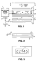
- FIG. 1 is an exploded side view of one embodiment of the invention.
- FIG. 2 is an exploded side view of another embodiment which is a partial modification of FIG. 1 .
- FIG. 3 is a plan view showing a liquid crystal display taken along the line 3 — 3 of FIG. 1 .
- FIG. 1 shows an exploded liquid crystal display (LCD) apparatus which as illustrated in FIG. 3 is part of a clock having the digital LCD segments 10 indicating the time of 22:45. As will be discussed in detail below in one mode (the negative) the segments will have a specific color on a black background. The user views the clock and its display in the same direction as the ambient light shown by arrow 11 in FIG. 1 .
- LCD liquid crystal display
- FIG. 1 shows an exploded liquid crystal display (LCD) apparatus which as illustrated in FIG. 3 is part of a clock having the digital LCD segments 10 indicating the time of 22:45. As will be discussed in detail below, in one mode (the negative) the segments will have a specific color on a black background. The user views the clock and its display in the same direction as the ambient light shown by arrow 11 in FIG. 1 .
- LCD liquid crystal display
- the liquid crystal assembly consists of a layer 12 of liquid crystal material sandwiched between a pair of transparent plates 13 , 14 typically of glass which carry patterned electrodes 16 made of indium tin oxide; these when activated by a multiplexed voltage from driver 17 rearrange or realign the crystals between the electrodes to block or allow the transmission of light (depending on whether a positive or negative mode of operation is being used) thus providing the desired digital display.
- a front polarizing layer 18 is attached to the visible side of plate or substrate 13 and a rear polarizing layer 19 to bottom plate or substrate 14 .
- the two polarizing layers 18 , 19 have transmission axes either aligned or rotated up to 90 degrees.
- a reflector 21 will return any light transmitted to it back through the above assembly.
- the foregoing is a standard LCD device.
- the polarizers allow only light of one polarization to pass through while the orthogonal direction of the light components are absorbed.
- Light emerging from the front polarizing layer 13 undergoes a 90° shift or twist in polarization due to the inherent nature of the liquid crystal layer 12 . If the rear polarizing layer 14 is aligned so that its transmission axis is orthogonal with the front polarizer, then light can pass through completely and be reflected by reflector 21 . If the reflector is a silvery sheet of aluminum, the display will appear silvery in background.
- the liquid crystals under the electrodes will be realigned resulting in no 90° shift and thus light will be absorbed by the front polarizer resulting in black pixels. In this case the display is said to operate in the positive mode.
- the rear polarizer has its polarization in parallel with the front polarizer, light emerging from the non electrode portion of the liquid crystal layer will be absorbed causing a black background.
- a voltage is applied to the electrodes light will pass through creating silvery pixels; this is the negative mode of operation.
- a layer 22 of fluorescent material is printed on the visible side of reflector 21 . Its color is chosen by the user for the best spectral conversion efficiency for a particular application. For example, Rodamine red and Rodamine yellow dyes will produce reddish and yellowish colors for the digits 10 ( FIG. 3 ). Fluorescent materials are ideal for this application when excited by the incoming ambient light there is a spontaneous relaxation of the excited electrons to the ground state with a frequency shift (generally longer wavelength) resulting in an intensifying effect at the fluorescing frequency. In contrast, phosphors have a very long decay time and cannot replace fluorescent materials. However they are useful in combination to provide an afterglow at night when temporary backlighting is used. Thus layer 22 may also include phosphorescent material.
- Such reflector may be composed of translucent material such as a white plastic sheet or a white paper sheet.
- an electroluminescent plate 24 may be used powered by an electroluminance driver circuit connected to the battery 26 through switch 27 .
- a minimum amount of light is required because of the use of a translucent reflector.
- the LCD device is normally only battery powered as illustrated by battery 15 to driver 17 , use of backlighting should only be intermittent.
- FIG. 2 is an alternative backlight using a light cavity on a diffusing sheet 32 and a reflector 33 all of which are illuminated by light source 34 . This replaces plate 24 of FIG. 1 .
- the fluorescent layer 22 may also be attached at 22 ′ to the underside of polarizing layer 19 . It can be formed of a single layer of one color or a combination of patches of various colors.
- the rear polarizing layer 19 may also be a reflective polarizer film such as manufactured by the 3M Corporation under the trademark RDF-C or a double brightness enhancement polarizing film under the trademark DBEF by 3M.
- the driver 17 should have a duty cycle of at least 1 ⁇ 2. Any duty cycle less such as 1 ⁇ 4 will reduce the light contrast undesirably. This is due to less amount of light impinging onto the reflective layer under each pixel element.
Abstract
Description
Claims (6)
Priority Applications (6)
| Application Number | Priority Date | Filing Date | Title |
|---|---|---|---|
| US10/686,363 US7123317B2 (en) | 2003-10-14 | 2003-10-14 | Liquid crystal display with fluorescent material |
| DE202004002582U DE202004002582U1 (en) | 2003-10-14 | 2004-02-24 | Liquid crystal display with improved color |
| CNB2004100314062A CN100474059C (en) | 2003-10-14 | 2004-03-29 | Liquid crystal display with enhanced color |
| JP2004216975A JP5064648B2 (en) | 2003-10-14 | 2004-07-26 | Liquid crystal display device with enhanced color |
| HK05109045.1A HK1077099A1 (en) | 2003-10-14 | 2005-10-13 | Liquid crystal display with enhanced color |
| JP2012116905A JP2012230384A (en) | 2003-10-14 | 2012-05-22 | Liquid crystal display device with enhanced color |
Applications Claiming Priority (1)
| Application Number | Priority Date | Filing Date | Title |
|---|---|---|---|
| US10/686,363 US7123317B2 (en) | 2003-10-14 | 2003-10-14 | Liquid crystal display with fluorescent material |
Publications (2)
| Publication Number | Publication Date |
|---|---|
| US20050078236A1 US20050078236A1 (en) | 2005-04-14 |
| US7123317B2 true US7123317B2 (en) | 2006-10-17 |
Family
ID=32469834
Family Applications (1)
| Application Number | Title | Priority Date | Filing Date |
|---|---|---|---|
| US10/686,363 Expired - Lifetime US7123317B2 (en) | 2003-10-14 | 2003-10-14 | Liquid crystal display with fluorescent material |
Country Status (5)
| Country | Link |
|---|---|
| US (1) | US7123317B2 (en) |
| JP (2) | JP5064648B2 (en) |
| CN (1) | CN100474059C (en) |
| DE (1) | DE202004002582U1 (en) |
| HK (1) | HK1077099A1 (en) |
Cited By (3)
| Publication number | Priority date | Publication date | Assignee | Title |
|---|---|---|---|---|
| WO2014051633A1 (en) * | 2012-09-30 | 2014-04-03 | Hewlett-Packard Development Company, Lp | Transflective display with a light-recycling modulation layer |
| US20180011363A1 (en) * | 2016-07-05 | 2018-01-11 | Samsung Display Co., Ltd. | Display apparatus |
| CH714306A1 (en) * | 2017-11-07 | 2019-05-15 | Fgp Capital Sa | LCD screen. |
Families Citing this family (4)
| Publication number | Priority date | Publication date | Assignee | Title |
|---|---|---|---|---|
| EP2214150A4 (en) * | 2007-11-29 | 2011-02-23 | Sharp Kk | Image display device |
| DE102010001609A1 (en) * | 2010-02-04 | 2011-08-04 | MOMES GmbH, 69469 | Apparatus for near-eye information presentation |
| CN105164556A (en) * | 2013-04-25 | 2015-12-16 | 东友精细化工有限公司 | Optical laminate |
| JP2018036344A (en) * | 2016-08-30 | 2018-03-08 | 日本精機株式会社 | Display device |
Citations (7)
| Publication number | Priority date | Publication date | Assignee | Title |
|---|---|---|---|---|
| US4521775A (en) * | 1980-10-17 | 1985-06-04 | Texas Instruments Incorporated | Method of operating a stacked display |
| US5076668A (en) * | 1988-01-25 | 1991-12-31 | Taliq Corporation | Gain reflector-liquid crystal display |
| US5680188A (en) * | 1993-06-07 | 1997-10-21 | Casio Computer Co., Ltd. | Reflective liquid crystal display device |
| US5815228A (en) * | 1996-12-06 | 1998-09-29 | Ericsson Inc. | Lighting for liquid crystal displays |
| US6124971A (en) * | 1995-06-26 | 2000-09-26 | 3M Innovative Properties Company | Transflective displays with reflective polarizing transflector |
| US6147934A (en) * | 1997-06-09 | 2000-11-14 | Seiko Epson Corporation | Display device and electronic watch |
| US20040137224A1 (en) * | 2001-03-05 | 2004-07-15 | Nitto Denko Corporation | Polarizing plate and liquid crystal display using the same |
Family Cites Families (3)
| Publication number | Priority date | Publication date | Assignee | Title |
|---|---|---|---|---|
| JPS5448195A (en) * | 1977-09-22 | 1979-04-16 | Seiko Epson Corp | Liquid crystal display unit |
| JPS6153620A (en) * | 1984-08-24 | 1986-03-17 | Citizen Watch Co Ltd | Reflection type negative display device |
| JPH11109326A (en) * | 1997-09-30 | 1999-04-23 | Kawaguchiko Seimitsu Kk | Reflection type liquid crystal panel |
-
2003
- 2003-10-14 US US10/686,363 patent/US7123317B2/en not_active Expired - Lifetime
-
2004
- 2004-02-24 DE DE202004002582U patent/DE202004002582U1/en not_active Expired - Lifetime
- 2004-03-29 CN CNB2004100314062A patent/CN100474059C/en not_active Expired - Fee Related
- 2004-07-26 JP JP2004216975A patent/JP5064648B2/en not_active Expired - Fee Related
-
2005
- 2005-10-13 HK HK05109045.1A patent/HK1077099A1/en not_active IP Right Cessation
-
2012
- 2012-05-22 JP JP2012116905A patent/JP2012230384A/en active Pending
Patent Citations (7)
| Publication number | Priority date | Publication date | Assignee | Title |
|---|---|---|---|---|
| US4521775A (en) * | 1980-10-17 | 1985-06-04 | Texas Instruments Incorporated | Method of operating a stacked display |
| US5076668A (en) * | 1988-01-25 | 1991-12-31 | Taliq Corporation | Gain reflector-liquid crystal display |
| US5680188A (en) * | 1993-06-07 | 1997-10-21 | Casio Computer Co., Ltd. | Reflective liquid crystal display device |
| US6124971A (en) * | 1995-06-26 | 2000-09-26 | 3M Innovative Properties Company | Transflective displays with reflective polarizing transflector |
| US5815228A (en) * | 1996-12-06 | 1998-09-29 | Ericsson Inc. | Lighting for liquid crystal displays |
| US6147934A (en) * | 1997-06-09 | 2000-11-14 | Seiko Epson Corporation | Display device and electronic watch |
| US20040137224A1 (en) * | 2001-03-05 | 2004-07-15 | Nitto Denko Corporation | Polarizing plate and liquid crystal display using the same |
Cited By (4)
| Publication number | Priority date | Publication date | Assignee | Title |
|---|---|---|---|---|
| WO2014051633A1 (en) * | 2012-09-30 | 2014-04-03 | Hewlett-Packard Development Company, Lp | Transflective display with a light-recycling modulation layer |
| US20180011363A1 (en) * | 2016-07-05 | 2018-01-11 | Samsung Display Co., Ltd. | Display apparatus |
| US10571747B2 (en) * | 2016-07-05 | 2020-02-25 | Samsung Display Co., Ltd. | Display apparatus |
| CH714306A1 (en) * | 2017-11-07 | 2019-05-15 | Fgp Capital Sa | LCD screen. |
Also Published As
| Publication number | Publication date |
|---|---|
| US20050078236A1 (en) | 2005-04-14 |
| DE202004002582U1 (en) | 2004-05-27 |
| JP2005122115A (en) | 2005-05-12 |
| CN1607431A (en) | 2005-04-20 |
| JP2012230384A (en) | 2012-11-22 |
| HK1077099A1 (en) | 2006-02-03 |
| JP5064648B2 (en) | 2012-10-31 |
| CN100474059C (en) | 2009-04-01 |
Similar Documents
| Publication | Publication Date | Title |
|---|---|---|
| EP0877282B1 (en) | Liquid crystal display device and apparatus for using the same | |
| US6147934A (en) | Display device and electronic watch | |
| JP3405546B2 (en) | Liquid crystal display | |
| US5815228A (en) | Lighting for liquid crystal displays | |
| CN110221477B (en) | Array substrate, liquid crystal display screen and terminal | |
| JP2012230384A (en) | Liquid crystal display device with enhanced color | |
| US6184955B1 (en) | Liquid crystal device and electronic apparatus using it | |
| JPH10133591A (en) | Light guide type lighting device and light guide type display device | |
| JP2004354818A (en) | Display device | |
| JP2001264756A (en) | Liquid crystal device and electronic equipment | |
| JP2000066193A (en) | Liquid crystal display device and electronic equipment using the same | |
| EP0890866B1 (en) | Electronic watch | |
| JP2000305077A (en) | Solar battery laminated type liquid crystal display device | |
| EP1008894A1 (en) | Timepiece | |
| JP3544478B2 (en) | Transflective liquid crystal display | |
| KR20070034697A (en) | LCD and its driving method | |
| JP2000098360A (en) | Liquid crystal device | |
| CN109307960B (en) | Transparent liquid crystal display panel | |
| JP2004029121A (en) | Liquid crystal display device | |
| JP2004126294A (en) | Display device and personal digital assistant | |
| KR100730098B1 (en) | Color liquid crystal display | |
| JPH086013A (en) | Reflection type liquid crystal display device | |
| JP3184563U (en) | Liquid crystal display | |
| JP2000098359A (en) | Liquid crystal device | |
| JP2002014338A (en) | Liquid crystal display device and illumination device of the same |
Legal Events
| Date | Code | Title | Description |
|---|---|---|---|
| AS | Assignment |
Owner name: MONEREY INTERNATIONAL, LTD., CHINA Free format text: ASSIGNMENT OF ASSIGNORS INTEREST;ASSIGNOR:KWOK, JOSEPH TAK MING;REEL/FRAME:014612/0872 Effective date: 20030930 |
|
| REMI | Maintenance fee reminder mailed | ||
| FPAY | Fee payment |
Year of fee payment: 4 |
|
| SULP | Surcharge for late payment | ||
| REMI | Maintenance fee reminder mailed | ||
| FPAY | Fee payment |
Year of fee payment: 8 |
|
| SULP | Surcharge for late payment |
Year of fee payment: 7 |
|
| FEPP | Fee payment procedure |
Free format text: MAINTENANCE FEE REMINDER MAILED (ORIGINAL EVENT CODE: REM.) |
|
| LAPS | Lapse for failure to pay maintenance fees |
Free format text: PATENT EXPIRED FOR FAILURE TO PAY MAINTENANCE FEES (ORIGINAL EVENT CODE: EXP.); ENTITY STATUS OF PATENT OWNER: SMALL ENTITY |
|
| FP | Lapsed due to failure to pay maintenance fee |
Effective date: 20181017 |
|
| FEPP | Fee payment procedure |
Free format text: SURCHARGE, PETITION TO ACCEPT PYMT AFTER EXP, UNINTENTIONAL. (ORIGINAL EVENT CODE: M2558); ENTITY STATUS OF PATENT OWNER: SMALL ENTITY Free format text: PETITION RELATED TO MAINTENANCE FEES GRANTED (ORIGINAL EVENT CODE: PMFG); ENTITY STATUS OF PATENT OWNER: SMALL ENTITY Free format text: PETITION RELATED TO MAINTENANCE FEES FILED (ORIGINAL EVENT CODE: PMFP); ENTITY STATUS OF PATENT OWNER: SMALL ENTITY |
|
| MAFP | Maintenance fee payment |
Free format text: PAYMENT OF MAINTENANCE FEE, 12TH YR, SMALL ENTITY (ORIGINAL EVENT CODE: M2553); ENTITY STATUS OF PATENT OWNER: SMALL ENTITY Year of fee payment: 12 |
|
| PRDP | Patent reinstated due to the acceptance of a late maintenance fee |
Effective date: 20181224 |
|
| STCF | Information on status: patent grant |
Free format text: PATENTED CASE |