US7126998B2 - Envelope stabilization method and apparatus - Google Patents
Envelope stabilization method and apparatus Download PDFInfo
- Publication number
- US7126998B2 US7126998B2 US11/221,511 US22151105A US7126998B2 US 7126998 B2 US7126998 B2 US 7126998B2 US 22151105 A US22151105 A US 22151105A US 7126998 B2 US7126998 B2 US 7126998B2
- Authority
- US
- United States
- Prior art keywords
- signal
- samples
- partial response
- ones
- transmitter
- Prior art date
- Legal status (The legal status is an assumption and is not a legal conclusion. Google has not performed a legal analysis and makes no representation as to the accuracy of the status listed.)
- Expired - Lifetime
Links
Images


Classifications
-
- H—ELECTRICITY
- H04—ELECTRIC COMMUNICATION TECHNIQUE
- H04L—TRANSMISSION OF DIGITAL INFORMATION, e.g. TELEGRAPHIC COMMUNICATION
- H04L27/00—Modulated-carrier systems
- H04L27/26—Systems using multi-frequency codes
- H04L27/2601—Multicarrier modulation systems
- H04L27/2614—Peak power aspects
-
- H—ELECTRICITY
- H04—ELECTRIC COMMUNICATION TECHNIQUE
- H04L—TRANSMISSION OF DIGITAL INFORMATION, e.g. TELEGRAPHIC COMMUNICATION
- H04L25/00—Baseband systems
- H04L25/38—Synchronous or start-stop systems, e.g. for Baudot code
- H04L25/40—Transmitting circuits; Receiving circuits
- H04L25/49—Transmitting circuits; Receiving circuits using code conversion at the transmitter; using predistortion; using insertion of idle bits for obtaining a desired frequency spectrum; using three or more amplitude levels ; Baseband coding techniques specific to data transmission systems
- H04L25/497—Transmitting circuits; Receiving circuits using code conversion at the transmitter; using predistortion; using insertion of idle bits for obtaining a desired frequency spectrum; using three or more amplitude levels ; Baseband coding techniques specific to data transmission systems by correlative coding, e.g. partial response coding or echo modulation coding transmitters and receivers for partial response systems
-
- H—ELECTRICITY
- H04—ELECTRIC COMMUNICATION TECHNIQUE
- H04L—TRANSMISSION OF DIGITAL INFORMATION, e.g. TELEGRAPHIC COMMUNICATION
- H04L27/00—Modulated-carrier systems
- H04L27/26—Systems using multi-frequency codes
- H04L27/2601—Multicarrier modulation systems
- H04L27/2602—Signal structure
-
- H—ELECTRICITY
- H04—ELECTRIC COMMUNICATION TECHNIQUE
- H04L—TRANSMISSION OF DIGITAL INFORMATION, e.g. TELEGRAPHIC COMMUNICATION
- H04L27/00—Modulated-carrier systems
- H04L27/26—Systems using multi-frequency codes
- H04L27/2601—Multicarrier modulation systems
- H04L27/2614—Peak power aspects
- H04L27/2615—Reduction thereof using coding
Definitions
- the present invention relates generally to communication systems. More particularly, the present invention relates to the stabilization of a signal envelope for communication systems.
- Typical communication systems transmit information from one location or source to a second location or destination.
- the information travels from the source to the destination through a channel; this channel is typically a noisy channel.
- the channel introduces various forms of noise.
- the term “noise” is used herein to define various forms of signal corruption, such as interference, faxing, attenuation, environmental impact, and electronic noise, that alter the characteristics of a signal as it travels through a channel.
- the signal that is transmitted through the channel and received at a receiver may be a combination of the transmitted signal and the effects of noise introduced by the channel as a result of travelling through the channel.
- interference In a cellular communications system, one type of noise is called “interference”. More specifically, there may be at least two forms of interference in communication systems: co-channel interference (CCI) and inter-symbol interference (ISI).
- CCI arises in communication systems due in part to the fact that there are several transmitters in communication with the same receiving unit. The signal from one transmitter may interfere with the signal from another transmitter. Each transmitter may be an omni-directional transmitter. However, a signal being transmitted from one transmitter may take several paths as the signal travels from the transmitter to the receiver. This leads to ISI, which is a form of self-interference.
- CCI co-channel interference
- ISI inter-symbol interference
- modulation is the process of varying the characteristic of a carrier according to an established standard or scheme; the carrier is prepared or “modulated” by the information to produce a “modulated” carrier signal that is transmitted by the source to the destination through the channel.
- modulation is the process of varying the characteristics of the electrical carrier as information is being transmitted.
- the most common types of modulation are Frequency Modulation (FM), Amplitude Modulation (AM), and Phase Modulation (PM).
- OFDM Orthogonal Frequency Division Multiplexing
- Multi-carrier modulation is a technique for modulating multiple carriers with different information, all of which may be transmitted simultaneously or parallel in time.
- OFDM has high spectral efficiency as well as tolerance to multipath fading.
- transmitters are omni-directional and transmit in all directions.
- a signal emerging from a transmitter, or the source may travel multiple paths to reach the receiver, or the destination.
- multipath fading occurs on a carrier signal's intensity, which results in alteration of the information being carried.
- a conventional OFDM system comprises a set of sub-symbols X[k] transmitted in time using an Inverse Fast Fourier Transform (IFFT).
- IFFT Inverse Fast Fourier Transform
- x N and X N are the time and frequency domain symbol vectors, respectively.
- binary symbols or bit streams are encoded in the form of complex valued numbers.
- the complex valued numbers are drawn from an M-ary alphabet.
- the complex valued numbers are then used to modulate a set of orthogonal sub-carriers to generate a time-domain signal using an Inverse Discrete Fourier Transform (IDFT).
- IDFT Inverse Discrete Fourier Transform
- the resulting baseband signal which is usually complex valued, is quadrature modulated on a Radio Frequency (RF) carrier and transmitted through an air interface channel.
- RF Radio Frequency
- the channel is subject to fading due to multipath and path loss. Additionally, the channel may suffer from ISI which poses a problem at the receiver when data has to be detected. Furthermore, manufacturers of devices that transmit and receive data are always faced with the challenge of increasing the amount of and the rate at which information can be transmitted over a finite bandwidth while overcoming signal loss due to channel noise.
- Embodiments of the present invention are related to the implementation of Orthogonal Frequency Division Multiplexed (OFDM) systems.
- OFDM Orthogonal Frequency Division Multiplexed
- PAPR peak-to-average power ratio
- Coherent addition of the modulating sub-symbols can lead to an occasional peak in the signal that is several dB above average.
- a high PAPR usually implies that a very linear but inefficient power amplifier (PA) must be used for RF transmission.
- PA power amplifier
- Clipping is often the simplest solution proposed, but can lead to out-of-band distortion.
- a high PAPR typically implies that the power amplifiers at the transmitter end and the amplifiers at the receiver end need to be of very high linearity, and preferably of high efficiency too. It is very common to trade-off high linearity for efficiency in OFDM type of applications so that often highly linear but inefficient amplifiers end up being utilized.
- An embodiment of the present invention enables the use of efficient amplifiers potentially by stabilizing the envelope of the RF carrier in an OFDM system. Alternatively, it enables the use of the traditional amplifiers with greater output power. Partial response signaling is employed to compress the signal in time. Then the power envelope is shaped or more specifically, squared.
- the present invention accordingly, advantageously provides a system and method to reduce the peak to average power ratio (PAPR) for an OFDM system by stabilizing the signal envelope.
- PAPR peak to average power ratio
- PR partial response
- the signal is first compressed in time.
- the signal is then rearranged such that it is possible to stabilize the envelope, thus improving the PAPR without using excessive time-bandwidth resources.
- the compression provides extra time in which to stabilize the envelope.
- An advantage of an embodiment of the present invention is to be able to use an inexpensive and efficient amplifier or to be able to use a traditional class A amplifier with greater average output power.
- FIG. 1 is a graphical representation illustrating the real part of a partial response (PR) OFDM time-symbol with about 50% of the symbol duration carrying significant energy.
- PR partial response
- FIG. 2 is a graphical representation illustrating the imaginary part of a partial response (PR) OFDM time-symbol with about 50% of the symbol duration carrying significant energy.
- PR partial response
- FIG. 3 is a block diagram illustrative of an envelope shaping/squaring system for a Partial Response Orthogonal Frequency Division Multiplexing (PR-OFDM) in accordance with an embodiment of the present invention.
- PR-OFDM Partial Response Orthogonal Frequency Division Multiplexing
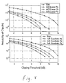
- FIG. 4 is a graphical representation of the probability of clipping for different pad-powers using linear feedback and quadratic feedback.
- FIG. 5 is a table listing the PAPR before and after envelope shaping/squaring.
- a novel apparatus and method to enable the use of inexpensive relatively more efficient amplifiers (instead of less efficient and expensive class-A amplifiers) with an OFDM system is provided.
- the use of high-efficiency amplifiers requires that signals with very stable envelopes only be amplified.
- An embodiment of the present invention provides a system and method by which the envelope of an OFDM signal (which fluctuates a lot under normal circumstances) is stabilized with tolerable loss in system bandwidth. In other words, the system strives to balance the envelope's amplitude and keep it nominally close to a predetermined value.
- Partial response signaling has been described in co-pending U.S. patent application Ser. No. 09/704,086, filed on Nov. 1, 2000, entitled PARTIAL RESPONSE SIGNALING FOR ORTHOGONAL FREQUENCY DIVISION MULTIPLEXING.
- PARTIAL RESPONSE SIGNALING FOR ORTHOGONAL FREQUENCY DIVISION MULTIPLEXING By choosing a suitable partial response polynomial, up to 50% of the signal in time can be rendered practically insignificant. That is to say, the signal across 50% of the OFDM symbol time-period can be closely approximated to zero with little loss of accuracy.
- Embodiments of the present invention may be used with any order M, although the bandwidth traded off (for envelope stability) is higher at lower M.
- System 10 may comprise transmitter 14 , channel 16 , and receiver 18 , wherein system 10 may utilize a Partial Response (PR)-Orthogonal Frequency Division Multiplexing (OFDM) signal modulation technique.
- Transmitter 14 may comprise mapper 22 , cyclic convolver 24 , serial-to-parallel converter unit 26 , Inverse Fast Fourier Transform (IFFT) unit 28 , parallel-to-serial converter unit 30 , and signal folder with envelope squarer 50 .
- Transmitter 14 transmits the information to receiver 18 through channel 16 .
- Channel 16 may be a noisy channel.
- Receiver 18 may comprise signal unfolder 60 , serial-to-parallel converter unit 34 , Fast Fourier Transform (FFT) unit 36 , parallel-to-serial converter unit 38 , Maximum Likelihood (ML) estimator unit 40 , and demapper unit 42 .
- FFT Fast Fourier Transform
- ML Maximum Likelihood
- Transmitter 14 transmits the carrier signal through channel 16 to receiver 18 .
- the carrier signal which may be a time based signal, travels through channel 16 , which may introduce noise to the carrier signal, such as x[n], corresponding to a channel impulse response, such as h[n], of channel 16 .
- Cyclic convolver unit 24 performs a cyclic convolution on the complex signal.
- cyclic convolver unit 24 may append a cyclic prefix (CP) at the leading edge or the beginning of the complex signal that also helps compensate for the effects of channel 16 and helps suppress Inter-Symbol Interference (ISI) in each of the low bit-rate sub-channels of the PR-OFDM signal.
- CP cyclic prefix
- the CP ensures that when channel 16 performs a convolution on each OFDM time-symbol the effect of channel 16 may be eliminated at receiver 18 .
- inter-subcarrier i.e., inter-channel
- ICI inter-channel interference
- the generated ICI is introduced to the complex signal by cyclic convolver unit 24 , as indicated above. Cyclic convolver unit 24 introduces, based on the desired or generated ICI, systematic or known amounts of dispersion to produce a partial response signal.
- the PR polynomial can be expressed as a zero-padded vector of length N with M non-zero terms.
- the transmitter 14 can effectively suppress energy in parts of the OFDM time symbol-vector, thereby producing a PR-OFDM symbol.
- cyclic convolver unit 24 generates a partial response signal with near zero energy at the extremities in the time domain.
- the partial response signal which is a frequency domain based signal, is then received by serial-to-parallel unit 26 .
- Serial-to-parallel unit 26 converts the partial response signal from serial to parallel signaling and passes the parallel partial response signal to IFFT unit 28 .
- IFFT unit 28 performs a modulation that is a transformation on the parallel partial response signal to generate real and imaginary components in the time domain.
- the transformed parallel partial response signal is derived from the partial response signal.
- the real and imaginary components of the transformed parallel partial response signal are received by the parallel-to-serial unit 30 , which coverts to serial signaling to produce a transformed partial response (PR) signal that is ready for signal folding, envelope shaping or squaring and transmission.
- PR transformed partial response
- the envelope amplitude at any instant is given by
- the compressed PR signal may now be rearranged in time. The signal is rearranged such that all the significant time-samples (in-phase and quadrature-phase samples) are placed on the in-phase carrier adjacent to one another.
- the quadrature-phase carrier may be used as a degree of freedom to shape or square the envelope of the modified signal. Squaring the envelope essentially means stabilizing it to a nominally constant value.
- the PR signal is received by signal folder and envelope squarer 50 .
- Signal folder and envelope squarer 50 separates the real and imaginary parts of the significant section of the symbol and places the real and imaginary parts adjacent to one another.
- the rearrangement may be represented by the time vector:.
- x′ ⁇ x Re [0], . . . , x Re [N ⁇ d],x Im [0], . . . , x Im [N ⁇ d] ⁇
- the in-phase carrier (I) is modulated with signal samples x′′ derived from x′.
- the quadrature phase carrier (Q) is used as a degree-of-freedom to shape or “square” the envelope by placing suitably calculated samples on the quadrature-phase carrier. For every sample on the in-phase carrier, a corresponding sample is placed on the quadrature-phase carrier. This process balances the envelope amplitude and keeps it nominally close to a predetermined value so that amplitude may be maintained within the linear threshold of an amplifier, thus, avoiding any non-linear effects.
- the envelope-stabilized signal may be represented as x′′ and the nominal envelope value may be denoted as ⁇ .
- Two embodiments of the present invention: one using linear feedback and another using Quadratic feedback may be described by means of the following equations:
- feedback equations Since the samples on the quadrature-phase carrier are used as feedback terms, the equations describing their generation are referred to as “feedback equations”.
- Step-II In linear feedback embodiment, an attempt is made to keep the sum of the magnitudes of the in-phase and quadrature samples constant. In quadrature feedback embodiment, an attempt is made to keep the sum of the magnitude squares a constant.
- the envelope has already been exceeded by the in-phase sample's magnitude (Step-II)
- the amplitude is halved. Notice that in one case (Step-I), the two samples x′′ Re and x′′ Im bear the same sign, while in another case (Step-II), the two samples x′′ Re and x′′ Im bear opposite signs. This is a simple artifice that will later help us reconstruct the original signal x at the receiver from the received signal x′′.
- the signal is reconstructed utilizing the in-phase signal received, and the quadrature-phase signal received [x′′ Re and x′′ Im ].
- the signal is reconstructed utilizing the estimated magnitude of y (y_mag) which is the absolute value of(x′′ Im +x′′ Re ).
- y_mag the absolute value of(x′′ Im +x′′ Re ).
- Step- 1 the magnitude of y (y_mag) should ideally be close to ⁇ ; else, if Step-II was used, the value of (y_mag) is ideally close to 0.
- the magnitude of Y (y_mag) becomes a tool to figure out whether we employed Step-I or Step-II in constructing the transmitted signal x′′.
- the folded partial response signal is transmitted through the channel 16 and received at the receiver 18 as a transmitted folded partial response signal.
- the transmitted folded partial response signal is received and unfolded at signal unfolder 60 .
- This may be implemented as an adder and a thresholding device.
- Signal unfolder 60 extracts the original PR-OFDM signal from the envelope squared PR-OFDM signal.
- a systematic way to decipher the phase (i.e. sign) of x′ from the transmitted signal values is provided.
- the quantity y_sign sign(x′′ Re +x′′ Im ,) or sign(x′′ Re ⁇ x′′ Im ), depending on whether Step-I or Step-II was used, respectively, in constructing x′′.
- the way x′′ is devised from x′, one can look at y_sign and reliably extract the sign of the in-phase component (which has the real and imaginary parts of the PR-OFDM symbol).
- y_mag and y_sign we can estimate the magnitude and phase of each of the real and imaginary components of the original PR-OFDM symbol.
- the unfolded signal undergoes zero-padding (to fill up to an N-long vector) and then passes to serial-to-parallel unit 34 and converted to a parallel transmitted partial response signal and passed to FFT unit 36 .
- FFT unit 36 performs the inverse transformation of the transformation performed by IFFT unit 28 and, hence, transforms the signal from a time domain based signal to a frequency domain based signal to produce a converted parallel transmitted partial response signal.
- the converted parallel transmitted partial response signal is passed to the parallel-to-serial unit 38 .
- Parallel-to-serial unit 38 changes the converted parallel transmitted partial response signal to a converted transmitted partial response signal.
- the converted transmitted partial response signal is passed to a maximum likelihood (ML) detector unit 40 .
- ML unit 40 unravels the converted transmitted partial response signal to produce or recover the complex-number based signal.
- Demapper unit 42 converts the complex-number based signal into a binary stream that is outputted from the receiver.
- the signal envelope is maintained at some constant value.
- this value is represented by ⁇ .
- the value of ⁇ is fixed at a few dB above the existing expected envelope power.
- the extra dBs added to the envelope is what is referred to as pad-power. It is an objective of an embodiment of the present invention to be able to use inexpensive and efficient amplifiers or use traditional amplifiers at greater output power.
- the time-extent of PR signal has been doubled from (N ⁇ d) to 2(N ⁇ d).
- the fractional time-overhead can be quantified as 2(1 ⁇ d/N).
- the real objective of using PR signaling is to reduce this time-overhead incurred when compared to not using PR signaling. Not using PR signaling essentially leads to a 100% time-overhead, which is a significant cost to pay. Since the PR signal helps omit d time-samples, it correspondingly reduces the time-overhead incurred for envelope squaring.
- FIG. 4 is a graph of the probability of clipping for different pad-powers using linear feedback and quadratic feedback.
- linear feedback we pad the envelope with 3–6 dB of extra power whereas with quadratic feedback we employ 1–4 dB pad-power (relative to the normal, average signal envelope).
- the clipping probability substantially decreases after using envelope squaring.
- quadratic feedback seems to offer comparable clipping probabilities at lower pad-powers than a linear feedback system. At least two orders of magnitude decrease in clipping probability can be observed at a clipping threshold of about 6 dB using both linear and quadratic feedback.
- FIG. 5 lists the PAPR before and after envelope squaring. Simulations were performed for QPSK modulation with 64 subcarriers.
- the nominal PAPR for normal OFDM signals turned out to be 12–13 dB.
- the PAPR improvement ranged from 3–6 dB as we increased the pad-power from 1–4 dB for quadratic feedback, and from 3–6 dB for linear feedback. These are fairly high improvements in PAPR that cannot be obtained by normal techniques such as using transform signaling (example: Hadamard transform) or using companding as suggested by some others.
Landscapes
- Engineering & Computer Science (AREA)
- Computer Networks & Wireless Communication (AREA)
- Signal Processing (AREA)
- Physics & Mathematics (AREA)
- Spectroscopy & Molecular Physics (AREA)
- Digital Transmission Methods That Use Modulated Carrier Waves (AREA)
Abstract
Description
xN=IFFT{XN}
c N =[c(0)c(1) . . . c(M−1)00 . . . 0]
xN=IFFT{XN{circle around (×)}cN}
eN=IFFT{cN}
p(r)=(1−r)m ;m=1,2, . . .
x′={x Re[0], . . . ,x Re [N−d],x Im[0], . . . ,x Im [N−d]}
Quadratic Feedback Equations
Claims (25)
Priority Applications (1)
| Application Number | Priority Date | Filing Date | Title |
|---|---|---|---|
| US11/221,511 US7126998B2 (en) | 2000-08-31 | 2005-09-08 | Envelope stabilization method and apparatus |
Applications Claiming Priority (4)
| Application Number | Priority Date | Filing Date | Title |
|---|---|---|---|
| US22957100P | 2000-08-31 | 2000-08-31 | |
| US09/704,086 US6999503B1 (en) | 2000-08-31 | 2000-11-01 | Partial response signaling for orthogonal frequency division multiplexing |
| US09/808,564 US7003025B2 (en) | 2000-08-31 | 2001-03-14 | Envelope stabilization method and apparatus |
| US11/221,511 US7126998B2 (en) | 2000-08-31 | 2005-09-08 | Envelope stabilization method and apparatus |
Related Parent Applications (1)
| Application Number | Title | Priority Date | Filing Date |
|---|---|---|---|
| US09/808,564 Division US7003025B2 (en) | 2000-08-31 | 2001-03-14 | Envelope stabilization method and apparatus |
Publications (2)
| Publication Number | Publication Date |
|---|---|
| US20060067414A1 US20060067414A1 (en) | 2006-03-30 |
| US7126998B2 true US7126998B2 (en) | 2006-10-24 |
Family
ID=36099049
Family Applications (2)
| Application Number | Title | Priority Date | Filing Date |
|---|---|---|---|
| US09/808,564 Expired - Fee Related US7003025B2 (en) | 2000-08-31 | 2001-03-14 | Envelope stabilization method and apparatus |
| US11/221,511 Expired - Lifetime US7126998B2 (en) | 2000-08-31 | 2005-09-08 | Envelope stabilization method and apparatus |
Family Applications Before (1)
| Application Number | Title | Priority Date | Filing Date |
|---|---|---|---|
| US09/808,564 Expired - Fee Related US7003025B2 (en) | 2000-08-31 | 2001-03-14 | Envelope stabilization method and apparatus |
Country Status (1)
| Country | Link |
|---|---|
| US (2) | US7003025B2 (en) |
Cited By (1)
| Publication number | Priority date | Publication date | Assignee | Title |
|---|---|---|---|---|
| US20060067382A1 (en) * | 2004-09-27 | 2006-03-30 | Yedidia Jonathan S | Unambiguously encoding and decoding signals for wireless channels |
Families Citing this family (8)
| Publication number | Priority date | Publication date | Assignee | Title |
|---|---|---|---|---|
| KR100429528B1 (en) * | 2002-01-23 | 2004-05-03 | 삼성전자주식회사 | Method and apparatus for digital communications |
| US7876838B2 (en) * | 2003-06-19 | 2011-01-25 | Univ Sydney | Low complexity multi-channel modulation method and apparatus |
| US20060274641A1 (en) * | 2005-04-04 | 2006-12-07 | Interdigital Technology Corporation | Method and apparatus for constant envelope orthogonal frequency division multiplexing in a wireless system |
| KR101084144B1 (en) * | 2005-11-09 | 2011-11-17 | 엘지전자 주식회사 | Method and apparatus for improving PAPR in OFDM or OFDMA communications system |
| CN102017486B (en) * | 2008-04-28 | 2015-07-01 | 夏普株式会社 | Radio communication system, radio communication device, and radio communication method |
| DE102009021417B4 (en) * | 2009-05-12 | 2014-09-04 | Paul Walter Baier | Method and apparatus for nonlinear transformation and envelope scaling of OFDM signals |
| US8804862B2 (en) | 2012-01-09 | 2014-08-12 | King Fahd University Of Petroleum And Minerals | Method of performing peak reduction and clipping mitigation |
| CN103532633B (en) * | 2012-07-04 | 2016-03-30 | 富士通株式会社 | A kind of automatic bias control method for optical sender and device |
Citations (11)
| Publication number | Priority date | Publication date | Assignee | Title |
|---|---|---|---|---|
| US5128964A (en) | 1990-10-10 | 1992-07-07 | Intelligent Modem Corporation | Modulation method and apparatus for multicarrier data transmission |
| US5675611A (en) | 1994-06-15 | 1997-10-07 | Nokia Mobile Phones Ltd. | Output power control and envelope shaping for a pulsed transmitter |
| US5694433A (en) | 1994-09-14 | 1997-12-02 | Ericsson Inc. | Efficient linear power amplification |
| US5943372A (en) | 1993-11-30 | 1999-08-24 | Lucent Technologies, Inc. | Orthogonal polarization and time varying offsetting of signals for digital data transmission or reception |
| US6157593A (en) | 1999-01-14 | 2000-12-05 | The United States Of America As Represented By The Secretary Of The Navy | Power envelope shaper |
| US20010050926A1 (en) * | 1996-06-19 | 2001-12-13 | Kumar Derek D. | In-band on-channel digital broadcasting method and system |
| US6343217B1 (en) | 1998-11-12 | 2002-01-29 | Legerity, Inc. | Digital cordless telephony with PCM coding |
| US20020138807A1 (en) * | 2001-03-26 | 2002-09-26 | Quang Nguyen | Optimum UMTS modem |
| US20040083254A1 (en) * | 2002-09-27 | 2004-04-29 | Heinrich Schenk | Circuit arrangement and method for compensating for disturbances in a signal generated by means of discrete multitone modulation |
| US20040152418A1 (en) * | 2002-11-06 | 2004-08-05 | Engim, Inc. | Unified digital front end for IEEE 802.11g WLAN system |
| US6973141B1 (en) * | 2001-10-04 | 2005-12-06 | Wideband Semiconductors, Inc. | Flexible multimode QAM modulator |
-
2001
- 2001-03-14 US US09/808,564 patent/US7003025B2/en not_active Expired - Fee Related
-
2005
- 2005-09-08 US US11/221,511 patent/US7126998B2/en not_active Expired - Lifetime
Patent Citations (11)
| Publication number | Priority date | Publication date | Assignee | Title |
|---|---|---|---|---|
| US5128964A (en) | 1990-10-10 | 1992-07-07 | Intelligent Modem Corporation | Modulation method and apparatus for multicarrier data transmission |
| US5943372A (en) | 1993-11-30 | 1999-08-24 | Lucent Technologies, Inc. | Orthogonal polarization and time varying offsetting of signals for digital data transmission or reception |
| US5675611A (en) | 1994-06-15 | 1997-10-07 | Nokia Mobile Phones Ltd. | Output power control and envelope shaping for a pulsed transmitter |
| US5694433A (en) | 1994-09-14 | 1997-12-02 | Ericsson Inc. | Efficient linear power amplification |
| US20010050926A1 (en) * | 1996-06-19 | 2001-12-13 | Kumar Derek D. | In-band on-channel digital broadcasting method and system |
| US6343217B1 (en) | 1998-11-12 | 2002-01-29 | Legerity, Inc. | Digital cordless telephony with PCM coding |
| US6157593A (en) | 1999-01-14 | 2000-12-05 | The United States Of America As Represented By The Secretary Of The Navy | Power envelope shaper |
| US20020138807A1 (en) * | 2001-03-26 | 2002-09-26 | Quang Nguyen | Optimum UMTS modem |
| US6973141B1 (en) * | 2001-10-04 | 2005-12-06 | Wideband Semiconductors, Inc. | Flexible multimode QAM modulator |
| US20040083254A1 (en) * | 2002-09-27 | 2004-04-29 | Heinrich Schenk | Circuit arrangement and method for compensating for disturbances in a signal generated by means of discrete multitone modulation |
| US20040152418A1 (en) * | 2002-11-06 | 2004-08-05 | Engim, Inc. | Unified digital front end for IEEE 802.11g WLAN system |
Cited By (2)
| Publication number | Priority date | Publication date | Assignee | Title |
|---|---|---|---|---|
| US20060067382A1 (en) * | 2004-09-27 | 2006-03-30 | Yedidia Jonathan S | Unambiguously encoding and decoding signals for wireless channels |
| US7376173B2 (en) * | 2004-09-27 | 2008-05-20 | Mitsubishi Electric Research Laboratories, Inc. | Unambiguously encoding and decoding signals for wireless channels |
Also Published As
| Publication number | Publication date |
|---|---|
| US20060067414A1 (en) | 2006-03-30 |
| US20020075840A1 (en) | 2002-06-20 |
| US7003025B2 (en) | 2006-02-21 |
Similar Documents
| Publication | Publication Date | Title |
|---|---|---|
| US7173961B2 (en) | Frequency domain partial response signaling with high spectral efficiency and low peak to average power ratio | |
| US7126998B2 (en) | Envelope stabilization method and apparatus | |
| JP4574095B2 (en) | Method and apparatus for reducing peak-to-average power ratio in a digital broadcasting system | |
| US7542517B2 (en) | Peak-to-average power reduction for FM OFDM transmission | |
| US6952394B1 (en) | Method for transmitting and receiving orthogonal frequency division multiplexing signal and apparatus therefor | |
| US7496028B2 (en) | Apparatus and method for minimizing PAPR in an OFDM communication system | |
| US7583738B2 (en) | Apparatus and method for reducing peak-to-average power ratio in orthogonal frequency division multiplexing communication system | |
| US7319723B2 (en) | Apparatus and method for reducing PAPR in an OFDM mobile communication system | |
| EP1713224B1 (en) | Peak power reduction method for wireless communication systems and corresponding transmitter | |
| US20150103815A1 (en) | Method and system for reduction of peak- to-average power ratio of transmission signals comprising overlapping waveforms | |
| US20140314187A1 (en) | Ofdm communication system and method having a reduced peak-to-average power ratio | |
| Sathananthan et al. | Coding to reduce both PAR and PICR of an OFDM signal | |
| US6781951B1 (en) | Radio communication system | |
| US6999503B1 (en) | Partial response signaling for orthogonal frequency division multiplexing | |
| Jayalath et al. | Peak-to-average power ratio of IEEE 802.11 a PHY layer signals | |
| Vadde et al. | Partial response signaling for enhanced spectral efficiency and RF performance in OFDM systems | |
| Ramtej et al. | PAPR reduction in LTE uplink communications by airy companding transform | |
| Al-Rayif et al. | Experimental demonstration for PAPR reduction in OFDM system using partial-OSLM technique | |
| Vadde | PAPR reduction by envelope stabilization using partial response signaling in OFDM systems | |
| Ramtej et al. | Exponential Companding Transform to Mitigate PAPR in SC-FDMA Systems | |
| Sathananthan et al. | Novel adaptive modulation scheme to reduce both PAR and ICI of an OFDM signal | |
| Alsisi | Constant Envelope DCT-and FFT-based Multicarrier Systems | |
| Vijay et al. | Novel Schemes for Minimizing the PAPR in LTE-OFDM System | |
| Patel et al. | PAPR Reduction Techniques in OFDM System | |
| Nagalikar et al. | Adaptive Clipping for PAPR Reduction in OFDM |
Legal Events
| Date | Code | Title | Description |
|---|---|---|---|
| STCF | Information on status: patent grant |
Free format text: PATENTED CASE |
|
| FPAY | Fee payment |
Year of fee payment: 4 |
|
| FPAY | Fee payment |
Year of fee payment: 8 |
|
| MAFP | Maintenance fee payment |
Free format text: PAYMENT OF MAINTENANCE FEE, 12TH YEAR, LARGE ENTITY (ORIGINAL EVENT CODE: M1553) Year of fee payment: 12 |
|
| AS | Assignment |
Owner name: WSOU INVESTMENTS LLC, CALIFORNIA Free format text: ASSIGNMENT OF ASSIGNORS INTEREST;ASSIGNOR:NOKIA TECHNOLOGIES OY;REEL/FRAME:052694/0303 Effective date: 20170822 |
|
| AS | Assignment |
Owner name: OT WSOU TERRIER HOLDINGS, LLC, CALIFORNIA Free format text: SECURITY INTEREST;ASSIGNOR:WSOU INVESTMENTS, LLC;REEL/FRAME:056990/0081 Effective date: 20210528 |