US7136547B2 - Method and apparatus for beam deflection - Google Patents
Method and apparatus for beam deflection Download PDFInfo
- Publication number
- US7136547B2 US7136547B2 US10/075,930 US7593002A US7136547B2 US 7136547 B2 US7136547 B2 US 7136547B2 US 7593002 A US7593002 A US 7593002A US 7136547 B2 US7136547 B2 US 7136547B2
- Authority
- US
- United States
- Prior art keywords
- stator
- movable member
- magnetic
- current
- force
- Prior art date
- Legal status (The legal status is an assumption and is not a legal conclusion. Google has not performed a legal analysis and makes no representation as to the accuracy of the status listed.)
- Expired - Fee Related, expires
Links
Images


Classifications
-
- G—PHYSICS
- G02—OPTICS
- G02B—OPTICAL ELEMENTS, SYSTEMS OR APPARATUS
- G02B6/00—Light guides; Structural details of arrangements comprising light guides and other optical elements, e.g. couplings
- G02B6/24—Coupling light guides
- G02B6/26—Optical coupling means
- G02B6/35—Optical coupling means having switching means
- G02B6/3564—Mechanical details of the actuation mechanism associated with the moving element or mounting mechanism details
- G02B6/3568—Mechanical details of the actuation mechanism associated with the moving element or mounting mechanism details characterised by the actuating force
- G02B6/3572—Magnetic force
-
- G—PHYSICS
- G02—OPTICS
- G02B—OPTICAL ELEMENTS, SYSTEMS OR APPARATUS
- G02B26/00—Optical devices or arrangements for the control of light using movable or deformable optical elements
- G02B26/08—Optical devices or arrangements for the control of light using movable or deformable optical elements for controlling the direction of light
- G02B26/0816—Optical devices or arrangements for the control of light using movable or deformable optical elements for controlling the direction of light by means of one or more reflecting elements
-
- G—PHYSICS
- G02—OPTICS
- G02B—OPTICAL ELEMENTS, SYSTEMS OR APPARATUS
- G02B26/00—Optical devices or arrangements for the control of light using movable or deformable optical elements
- G02B26/08—Optical devices or arrangements for the control of light using movable or deformable optical elements for controlling the direction of light
- G02B26/10—Scanning systems
- G02B26/105—Scanning systems with one or more pivoting mirrors or galvano-mirrors
-
- G—PHYSICS
- G02—OPTICS
- G02B—OPTICAL ELEMENTS, SYSTEMS OR APPARATUS
- G02B6/00—Light guides; Structural details of arrangements comprising light guides and other optical elements, e.g. couplings
- G02B6/24—Coupling light guides
- G02B6/26—Optical coupling means
- G02B6/35—Optical coupling means having switching means
- G02B6/351—Optical coupling means having switching means involving stationary waveguides with moving interposed optical elements
- G02B6/3512—Optical coupling means having switching means involving stationary waveguides with moving interposed optical elements the optical element being reflective, e.g. mirror
- G02B6/3518—Optical coupling means having switching means involving stationary waveguides with moving interposed optical elements the optical element being reflective, e.g. mirror the reflective optical element being an intrinsic part of a MEMS device, i.e. fabricated together with the MEMS device
-
- G—PHYSICS
- G02—OPTICS
- G02B—OPTICAL ELEMENTS, SYSTEMS OR APPARATUS
- G02B6/00—Light guides; Structural details of arrangements comprising light guides and other optical elements, e.g. couplings
- G02B6/24—Coupling light guides
- G02B6/26—Optical coupling means
- G02B6/35—Optical coupling means having switching means
- G02B6/354—Switching arrangements, i.e. number of input/output ports and interconnection types
- G02B6/3554—3D constellations, i.e. with switching elements and switched beams located in a volume
- G02B6/3556—NxM switch, i.e. regular arrays of switches elements of matrix type constellation
-
- G—PHYSICS
- G02—OPTICS
- G02B—OPTICAL ELEMENTS, SYSTEMS OR APPARATUS
- G02B6/00—Light guides; Structural details of arrangements comprising light guides and other optical elements, e.g. couplings
- G02B6/24—Coupling light guides
- G02B6/26—Optical coupling means
- G02B6/35—Optical coupling means having switching means
- G02B6/3564—Mechanical details of the actuation mechanism associated with the moving element or mounting mechanism details
- G02B6/3584—Mechanical details of the actuation mechanism associated with the moving element or mounting mechanism details constructional details of an associated actuator having a MEMS construction, i.e. constructed using semiconductor technology such as etching
-
- G—PHYSICS
- G02—OPTICS
- G02B—OPTICAL ELEMENTS, SYSTEMS OR APPARATUS
- G02B6/00—Light guides; Structural details of arrangements comprising light guides and other optical elements, e.g. couplings
- G02B6/24—Coupling light guides
- G02B6/26—Optical coupling means
- G02B6/35—Optical coupling means having switching means
- G02B6/3586—Control or adjustment details, e.g. calibrating
- G02B6/359—Control or adjustment details, e.g. calibrating of the position of the moving element itself during switching, i.e. without monitoring the switched beams
-
- G—PHYSICS
- G02—OPTICS
- G02B—OPTICAL ELEMENTS, SYSTEMS OR APPARATUS
- G02B7/00—Mountings, adjusting means, or light-tight connections, for optical elements
- G02B7/18—Mountings, adjusting means, or light-tight connections, for optical elements for prisms; for mirrors
- G02B7/182—Mountings, adjusting means, or light-tight connections, for optical elements for prisms; for mirrors for mirrors
- G02B7/1822—Mountings, adjusting means, or light-tight connections, for optical elements for prisms; for mirrors for mirrors comprising means for aligning the optical axis
- G02B7/1827—Motorised alignment
- G02B7/1828—Motorised alignment using magnetic means
Definitions
- the present invention relates to a mechanism for directing an optical beam in free space by controlled angular movement of an optical element in one or two dimensions.
- the invention relates to a beam steering device for use in a free space Optical Cross connect (OCX) switch used in a fiber to fiber telecommunications switching application or in an optical beam scanning apparatus for directing a beam in a desired pattern of movement.
- OCX Optical Cross connect
- micro mirror actuator systems of prior art designs include movable mirror elements that are typically rotated through a small angle in one or two planes by pairs of electronic actuators.
- the actuator may be mounted on a surface underlying the mirror and directly below unattached portions of the mirror. When a current or voltage is delivered to the actuator the unattached edge of the mirror is drawn toward the actuator by an electrical force moving the unattached portion of the mirror towards the underlying surface.
- Such devices usually use active closed loop electronic drivers that are always in an “on” state in order to hold the unattached mirror edge in a particular position. These devices require continuous consumption of power, to maintain the position. With each actuator dissipating just a fraction of a watt, the system load can total hundreds of watts of power for large actuator counts. This power generates heat that must be cooled and the total power load must be backed up in case of disruption, with battery and generator systems causing additional complexity and cost.
- FIG. 1 depicts a typical MEMs construction in which a gimbaled mirror assembly 1000 includes a movable mirror 1002 suspended on fine gimbaled structures or thin hinges 1004 and 1006 for rotation about a Y axis and suspended on fine gimbaled structure or thin hinges 1008 and 1010 for rotation about a X axis.
- the MEMs gimbaled mirror 1000 is mounted to an actuator layer 1012 , shown cut away, which includes actuator elements for attracting a free edge of the mirror toward the actuator layer 1012 .
- an actuating force applied to the mirror 1002 from the actuating surface 1012 draws a free edge of the mirror toward the actuator surface 1012 in the direction of the arrow shown at A.
- the mirror 1002 pivots about the Y-axis at the gimbals 1004 and 1006 such that the mirror at point B is raised with respect to the actuator surface 1012 as shown by the arrow at B.
- an actuator on the actuator surface 1012 near a point C draws another free end of the mirror in the direction of the arrow shown at C.
- the mirror 1002 pivots about the X-axis at the gimbals 1008 and 1010 such that the mirror at point D is raised with respect to the actuator surface 1012 as shown by the arrow at D.
- Single axis devices are also known for providing tilt about a single axis only.
- the actuator devices may employ electro-static, electromagnetic piezo-electric and mechanical actuator forces.
- the gimbaled mirror assembly 1000 may be formed of a silicon or poly-silicon structure deposited or otherwise formed onto the actuator layer.
- a Metal Oxide Chemical Vapor Deposition comprising a coating of e.g. aluminum, silver, gold or another reflective material coats the surface 1002 .
- the reflectivity of such layers is usually limited to about 96 to 98%.
- a prior art MEMs device like the one shown in FIG. 1A has been described by Lucent Technologies and may have a mirror diameter in the range of about 100-500 um (0.025-0.127 in.).
- FIG. 1B depicts a plurality of optical switching mirror assemblies 1000 .
- One commercially available example provides a 64 by 64 MEMS optical switch module having an operating temperature range of 5 to 70 degrees Centigrade, listed mirror switching time of 20 ms, with a power dissipation consumption of 15 watts. Insertion loss is 6 dB max (e.g. 75% losses); optical return loss is 30 dB, and cross channel isolation is 50 dB. Optical power transmission is limited to 31 milliwatts per port.
- each device 1000 is centered with respect to rows 1014 and columns 1016 . Such an arrangement provides a poor packing density for each device leaving a low mirror area to total area ratio.
- Optical switching system arrays of as few as two mirrors up to as many as 1024, or more, separate mirror elements may be required to be operating in an optical network switching hub.
- the mirror is surrounded mainly by air and lacks any conductive path to remove heat. This is one reason that conventional MEMS mirror devices are limited to low power, e.g. only 31 mw in the above example. Since the reflective surface of each mirror is typically limited to about 96 to 98% reflectivity, 2 to 4% of the light energy reaching the mirror may be absorbed by the mirror substrate or scattered, thereby heating the mirror substrate and the surrounding elements.
- MEMS mirrors are also thin and subject to surface distortion caused by thermal stress such as may result from the heat absorbed by the substrate and by the always-on actuators.
- Other surface distorting factors include mechanical forces developed during actuation and release of actuation and even sagging due to the MEMs mirror low stiffness. Vibration and shock loads may also lead to transient mirror surface distortion.
- Mirror surface distortions may cause beam distortions, e.g. wave front aberration, scattering and optical power fluctuations, possibly resulting in increasing optical losses, signal errors and channel cross talk.
- a mirror system of the highest attainable reflectivity, of the highest obtainable surface flatness or accuracy of surface figure and of the highest possible stiffness and with less optical energy absorption and or better heat dissipation capability would be beneficial and could be used to reflect much higher beam powers than are now reflected by MEMS systems.
- Reflective coatings in excess of 99.5 percent are realizable using multi-layer optical coatings under good process conditions. Such coatings are typically coated onto optical surfaces such as glass and metal and would be advantageous on optical switching mirrors to reduce scatter and absorption.
- these coatings have heretofore not been applied to conventional MEMs or other micro mechanical mirrors because the mirror structure is either too delicate for the coating environments or the mirror material is not compatible with accepting such coatings. Higher reflectivity coatings could reduce absorption in the mirror substrate.
- Mirror surfaces with a flatness of 1 ⁇ 2- 1/10 wave at the wavelength of the reflected light are routinely provided using conventional metal and glass mirror substrates by polishing. However, these polishing techniques have heretofore not been applied to conventional MEMS devices because the mirror structure is too small, too delicate, and not stiff enough or because the mirror material is not compatible with the polishing techniques.
- optical switching systems It is also desirable in optical switching systems to provide the lowest possible switch movement, settle and latch time for moving a mirror to a new position.
- FIG. 2 depicts a dual axis scanning device having first and second rotating mirrors 1018 , 1020 mounted on first and second rotation elements usually comprising a limited rotation motors or galvanometers 1022 , 1024 .
- Each limited rotation motor 1022 , 1024 is controlled by a servo or other style microprocessor controlled controller 1026 to rotate the mirrors through a desired angular range of just a few degrees up to 45 degrees or more.
- a radiation source 1028 and a source controller 1030 provide a radiation beam 1032 for directing onto a two-dimensional plane area 1034 .
- a lens 1036 may be provided to focus the beam 1032 in the plane 1034 .
- Each mirror 1018 and 1020 is individually controlled in its rotation angle to direct the radiation beam 1032 to any desired point in the plane 1034 .
- rotation of the mirror 1018 scans the beam along the X-axis of the plane 1034 and rotation of the mirror 1020 scans the beam along the Y-axis of the plane 1043 .
- Such a system as is depicted in FIG. 2 is capable of deflecting very high power optical beams without damage and provides very accurate beam placement capability.
- One drawback of the system is that it has heretofore been difficult to miniaturize.
- U.S. Pat. No. 6,154,302 discloses a light deflection device in the form of a reflective or refractive surface supported on a hemisphere or half-ball member, which is supported by its hemispherical surface on a dielectric liquid layer within a conforming socket or cavity of a base member.
- the ball has positive and negative chargeable regions made of different materials, so that turning torque is applied to the ball by the electrostatic force from an electric field in the dielectric liquid created by electrodes distributed around the cavity in the base member, to which a suitable voltage is applied.
- the electrostatic turning torque alters the tilt or angular position of the hemispherical member axis relative to the base member, until a position of equilibrium corresponding to the applied voltage is reached.
- a variation contemplates a magnetic film on the ball, and an electromagnet on the base member, where rotation is controlled by magnetic force between the film and the electromagnet. Friction in some cases and lack of any turning torque in other cases is said to hold the ball stationary in the cavity after the electric field is extinguished. An array of such elements is also shown.
- One drawback of the invention by Yagi et al. is the need immerse the hemispherical elements within the dielectric liquid layer.
- Sakata et al's U.S. Pat. No. 6,201,644 B1 of which Yagi is a co-inventor, describes a light deflection device and optical switching array, using a spherical body or half-ball and cavity similar in general appearance to Yagi's, with similar driving mechanisms for tilting the ball and with the same dielectric liquid layer.
- U.S. Pat. No. 4,436,260 illustrates a refracting optical scanner based on a hemispherical and a cylindrical shaped element with a mating conforming socket or cavity of a base member.
- a planar surface of the hemispherical or cylindrical is adjustable for relative tilt of a planar optical surface with respect to the base.
- a very small air bearing function facilitates relative sliding movement on the spherical interface between the components.
- a mechanical gimbal mechanism offset from the nominal plane of the optical components by a four-point pushrod linkage arrangement, permits control of the tilt angle between the two optical components, affecting control of the beam deflection angle. This invention does not provide an easily controllable actuation force especially for small angles.
- Swain et al's U.S. Pat. No. 4,961,627 illustrates a hemispherical element with a mating conforming socket or cavity of a base member.
- a planar surface of the hemispherical element is adjustable for relative tilt of a planar optical surface with respect to the base for refracting a beam passing through the hemispherical element.
- a fluid filled gap separates the hemispherical element from the base.
- Piezoelectric actuators about the perimeter of the device provide for relative tilting of one component to the other.
- a fluid seal is required and that the beam passes through the fluid.
- the invention provides a method and apparatus for directing a radiation beam in a desired direction.
- a movable member supported for movement by a fixed member and movable member has an optical element, e.g., a flat mirror fixedly attached thereto.
- the mirror scans a radiation beam incident thereon in one plane.
- the radiation beam is scanned in two mutually perpendicular planes.
- a magnetic element having a north and a south magnetic pole is fixedly attached to the movable member.
- a magnetically permeable stator element that is stationary with respect to the movable member and the magnetic element is placed in the field of the magnetic element such that the stator element and said magnetic element mutually generate a magnetic traction force between them.
- a current coil is wound around a portion of the stator element and a current driver is provided for driving a current in the current coil.
- the current induces an electromagnetic force in the stator element and the electromagnetic force acts on the magnetic element for controlling movement of the optical element with respect to the fixed element.
- a radiation beam source may be directed onto the movable mirror surface and scanned by the movement of the mirror to direct the radiation beam in a desired propagation direction.
- the movable member includes a first side having the optical element attached thereto and an opposing second side comprising an outer bearing surface.
- the fixed member includes an inner bearing seat formed in a thin flat plate for receiving the outer bearing surface therein.
- the movable member is accessible from the first and the second side when supported by the fixed member.
- a coefficient of friction exists between the outer bearing surface and the inner bearing seat and the magnetic tractive force provided by the magnetic element in combination with the coefficient of friction provides a clamping force for holding the movable member in a stationary orientation when no current is passing through the current coil.
- the device also includes position or orientation sensors attached to the stator or fixed member for sensing a position or orientation of the movable member or the mirror surface.
- a radiation source, fiber optic element, radiation detector or any other device may be attached to the movable member for movement therewith.
- the invention also includes a servo controlled current driver for driving a current to the current coils for controlling the movement of the movable element in a desired manner.
- FIG. 1A is a prior art top view of a moveable, optical beam mirror assembly.
- FIG. 1B is a prior art view depicting a portion of an array of movable optical mirrors.
- FIG. 2 is a prior art perspective view of a two-axis laser scanning system.
- FIG. 3A is a cross section view of a preferred embodiment of the invention.
- FIG. 3B is a single axis steering device.
- FIG. 4 is a bottom view of the embodiment of FIG. 3 A.
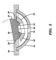
- FIG. 5 is a partial cross section view of the embodiment of FIG. 3A , the coils being omitted for clarity.
- FIG. 6 is a bottom view of the structure of FIG. 5 .
- FIGS. 7A , B, C, and D are partial cross section views of embodiments with different magnet ring configurations.
- FIG. 8 is a diagrammatic plan view of the lower end of the stator and coil windings of the embodiment of FIG. 3 A.
- FIG. 9 is a schematic of the flux circuit of the embodiment of FIG. 3 A.
- FIG. 10 is the cross section of FIG. 3A , illustrating the magnetic forces of the embodiment with force diagrams.
- FIG. 11 is a lower end view of an array of the devices of FIG. 3A , illustrating the packing arrangement for best area density yield.
- FIG. 12 is a cross section view of a single magnet embodiment with a core magnet of vertical orientation and a dual axis stator and coil assembly.
- FIG. 13 is a horizontal section view of the device of FIG. 12 , showing the dual axis coil assembly in plan form.
- FIG. 14 is a cross section of the device in FIG. 3A , configured with a capacitive position sensor.
- FIG. 15 is a diagrammatic cross section view of an embodiment of the invention configured with an image conduit connecting to remote light source and position sensor.
- FIGS. 16A , B and C are detailed views of portions of the embodiment of FIG. 15 .
- FIG. 17 is a side elevation of yet another embodiment of the invention incorporating a right angle light source, beam reflector, and optical position sensor mechanism.
- FIG. 18 is a single channel representation of a fiber-to-fiber optical link control system, illustrating beam splitter optical position sensors as components of the system.
- FIG. 19 is a single channel representation of a fiber-to-fiber optical link control system, illustrating fiber tap optical position sensors as components of the system.
- FIG. 20 is a matrix array of two banks of deflectors of the invention, providing an optical link between multiple fibers.
- FIG. 21 is a steering device having mechanical position sensors.
- FIG. 22 is an electronic servo controller for driving a control current to the stator coils.
- FIG. 23 is a radiation scanning system for scanning two and three-dimensional objects.
- FIG. 24A is a radiation scanning system having a radiation source attached to the movable element.
- FIG. 24B is a radiation scanning system having a flexible beam conduit attached to the movable member for directing a beam exiting from the conduit.
- FIG. 3A depicts a sectional view showing a two axis optical beam steering apparatus 5 in the general form of a ball and socket assembly. It is comprised of a movable member 10 in the form of a spherical or ball portion having an outer bearing surface 11 supported in a fixed member 40 that includes a spherical raceway or socket 20 for forming a seat in which the movable member 10 is movably supported for rotation with respect thereto.
- the fixed member 40 in the present example comprises a thin flat plate but may have other configurations.
- the movable member 10 and the fixed member 40 each includes a first side 6 and an opposing second side 8 .
- the fixed member 40 is configured to provide free access to the movable member 10 on each of the first side 6 and the second side 8 .
- the beam steerer 5 includes a mirror surface 30 for reflecting an optical beam therefrom and redirecting the beam to a desired target location by controlled movement of the surface 30 .
- the movable member may be used to control the movement of other surfaces, objects or elements, as will be detailed below.
- the mirror surface 30 may be either directly deposited onto, or attached onto, the movable member 10 .
- the surface 30 comprises an equatorial plane of the spherical or ball member 10 .
- the mirror surface 30 may be formed on other planes of the spherical section, which may or may not be parallel with the equatorial plane.
- FIG. 3A The sectional view of FIG. 3A , is taken through a second equatorial plane of the spherical or ball member 10 that is perpendicular to the surface 30 .
- a radial center 32 of the spherical or ball member 10 is shown on the surface 30 and represents an axis of rotation for the spherical or ball member 10 .
- a reflected beam or ray 36 is deflected through an angle that is double the angle ⁇ moved by the surface 30 .
- the mirror surface 30 has a second tilt angle in a plane perpendicular to the equatorial section shown in FIG. 3 A. The second tilt angle is not shown. Accordingly, an input ray 34 may be reflected at a reflection angle that may be any angle contained with a solid cone of angle centered on the rotation axis 32 .
- a magnetic element 50 Integral to or attached to of the movable member 10 on the second side 8 thereof is a magnetic element 50 comprising a magnetic ring.
- the magnetic ring 50 is formed and attached to the ball 10 in a manner providing clearance between the ring 50 and the fixed member 40 for allowing the ball 10 to be rotated about the axis 32 through the angle ⁇ and a perpendicular tilt angle, not shown.
- Magnet ring 50 is made up of four magnet portions 50 a-d, an opposing pair of which, 50 a and 50 c are shown in the section view of FIG. 3 A.
- Each magnetic section comprises opposing north and south magnetic poles, labeled N and S respectively in FIG. 3 A and 7 A- 7 D, such that a magnetic flux passes through each magnet section from one pole to the opposing pole.
- opposing magnet portions e.g. 50 a and 50 c have a south magnetic pole facing the ball 10 and a north magnetic pole facing away from the ball 10 .
- adjacent magnet section have oppositely oriented poles such that in the present example, magnet portions 50 b and 50 d have a north magnetic pole facing the ball 10 and a south magnetic pole facing away from the ball 10 .
- the ring 50 may be assembled from substantially same sized magnet portions each forming a quarter portion of the ring 50 or the ring 50 may be formed as a single monolithic magnet. As will be detailed further below, the magnetic ring 50 may be formed integral with the ball 10 .
- the second side 8 of the steering apparatus 5 is shown in FIG. 6.
- a fixedly supported stator element, referred to generally by the reference numeral 70 is provided proximate to the magnetic element 50 such that an air gap is provided between the magnetic element 50 and the stator element 70 .
- the stator element 70 comprises a magnetically permeable material and from one element of a magnetic circuit.
- the stator element 70 of FIG. 6 further comprises a cruciform element having four stator arms 70 a-d corresponding to each of the four magnet ring portions 50 a-d . As can best be seen in FIG.
- a uniform thickness air gap 73 is formed between each stator arm 70 a-d and each magnet ring portions 50 a-d by forming the stator arms substantially about a spherical radius centered with respect to the rotation axis 32 , of the ball 10 .
- the stator 70 is fixedly attached to the fixed member 40 .
- the stator element 70 is shown in a flat condition in FIG. 8 for clarity.
- a magnetic attraction force or traction force
- the traction force which acts across the air gap 73 , tends to draw the movable member 10 toward the fixed member 40 , such that in the preferred embodiment, the spherical ball 10 is drawing into a seated arrangement with the spherical bearing race 20 .
- the ball 10 With sufficient magnetic traction force, and with sufficient friction in the ball bearing seat interface, the ball 10 can be firmly held in a fixed orientation by the magnetic traction force for an indefinite period.
- the stator 70 further comprises stator current coils 60 a-d, wound onto respective stator arms 70 a-d, shown from side 8 in FIG. 4 and shown flat in FIG. 8 .
- opposing stator arms 70 a and 70 c and associated stator coils 60 a and 60 c are fanned to substantially conform to the spherical shape of the ball 10 at a substantially uniform radius from the radial center 32 with distal ends of each stator arm 70 a and 70 c fitted into a recess 71 on an underside of the plate 40 .
- Each stator arm 70 a-d is fixedly attached to the fixed element or plate 40 by bonding, soldering or by any appropriate attachment method.
- Each stator coil 60 a-d is wound to substantially perpendicularly intersect magnetic flux lines in the air gap 73 , as will be further described below. As is shown in FIG. 8 the coils are wound perpendicularly to a longitudinal axis 74 of the stator arms 70 a-d.
- stator coils e.g. coil 60 a
- a current coil 60 a induces a magnetic force having a force direction along a longitudinal axis of stator arm 70 a .
- a current in a first direction might cause a clockwise force thereby proving a clockwise rotation of the ball 10 , e.g. through angle ⁇ , and a current in the opposite direction creates a counter-clockwise magnetic force for rotating the ball 10 counter-clockwise.
- all four coils 60 a, b, c and d can be excited with independent currents in both direction and magnitude by one or more current drive circuits.
- opposing current coils may be connected to the same driver either in series or in parallel such that opposing coils are simultaneously driven by the same current source.
- the magnetic force generated along a longitudinal axis of each stator arm 70 a- 70 d can be used to rotate the ball 10 within the seat 20 in a controlled manner.
- the ball 10 may be rotated in two mutually perpendicular axes, thereby tilting the mirror surface 30 in two mutually perpendicular axes as well.
- current drivers may provide a clamping force across the air gap 73 .
- the claiming force is applied by driving all four coils to provide a force substantially toward a center aperture 72 of the stator element 70 such that the magnetic element 50 is attracted toward the aperture 72 and the attached movable member 10 is draw by a greater force into the bearing seat 20 .
- a clamping force is also provided when little or no current is applied to the coils 60 because as stated above, a traction force between the magnetic element 50 and the stator 70 is provided even without current in the coils 60 .
- levitation current is applied to the coils 60 that generate an induced magnetic levitation force in the stator 70 that substantially directly opposes the clamping force between the magnetic element 50 and the stator 70 .
- the levitation force may have sufficient magnitude to actually lift the movable member 10 for providing a clearance between the ball 10 and the bearing seat 20 or the levitation force may just reduce the clamping force between the magnetic element 50 and the stator 70 .
- a torque current is applied to the coils 60 for generating induced torque forces in the stator 70 .
- the torque forces are substantially directed along the longitudinal axes 74 of the stator arms 70 a-d and magnetic forces are imparted to the magnetic element 50 for rotating the movable member 10 .
- two mutually perpendicular rotations may be achieved by driving mutually perpendicular coils with an appropriate current.
- any even number of opposing magnet sections, stator arms and stator coils may be provided to rotate the movable element about a separate axis corresponding to each opposing pair of magnets, stator arms and coils.
- a first flux path passes between the north and south poles of magnet portion, 50 a , through the ball 10 between the south and north poles of the adjacent magnet portion 50 d across a first air gap 73 d and into stator arm 70 d .
- the magnetic flux lines then pass through the magnetically permeable stator element 70 from the arm 70 d to the adjacent stator arm 70 a , across a second air gap 73 a and return to the magnet portion 50 a .
- Each magnetic circuit is configured to create concentrated lines of magnetic flux radially across each air gaps 73 a - 73 d such that the magnet portions 50 a - 50 d are attracted to the stator element 70 which is fixedly attached to the fixed member 40 .
- a tractive force between the magnet portions and the stator across the air gap draws the ball 10 into the spherical raceway 20 .
- the movable member 10 is included in the magnetic circuit, the material of the movable member 10 will be beneficially magnetically permeable.
- the movable member 10 may include a magnetically permeable path, passing there through, which may be a separate element associated the movable member 10 .
- FIGS. 7A-7D variations of the magnet configuration offer varied manufacturing solutions, some examples of which are shown in FIGS. 7A-7D .
- the magnet portions 50 a-d can be integral with the ball geometry as shown in FIGS. 7A and 7C .
- the ball 10 may be removable from the fixed member 40 from the first side 6 without removing the magnetic element 50 .
- This configuration is convenient if it is desirable to periodically replace the movable member 10 in the event of a damaged mirror or the like.
- a removable or permanent retaining collars 41 as shown in partial cross section in FIG. 7 C. It may be added over ball 10 , attached to the first side 6 of plate 40 to insure that ball 10 does not unintentionally escape from its seat.
- the magnetic element 50 may be formed to extend outside the spherical form of the ball 10 as shown in FIGS. 7B and 7D .
- the magnet element 50 may further provide a retaining function for holding the ball in place in the event that a jarring shock for might cause the ball to dislodge from the bearing seat 20 .
- the protruding edges of magnet ring 50 can also serve as a limit stop against the underside of plate 40 for limiting the tilt angles of the surface 30 .
- FIGS. 7A and 7C further illustrate magnet configured with vertical magnetic pole orientations
- FIGS. 7B and 7D illustrate magnet configurations with radial magnetic pole orientations. Any of the configurations may be used, however, the configuration shown in FIG. 7D is the preferred embodiment because it offers the most efficient use of its magnetic volume while providing radial magnetic lines across the air gap 73 .
- a magnetically permeable back iron element 81 may be formed integral with an otherwise non-magnetically permeable ball member 10 to provide a magnetic flux path as shown in FIG. 9 .
- numerous other magnetic circuit elements and flux paths are usable without deviation from the scope of the present invention.
- the clamping force provided between the magnetic element 50 and the stator element 70 provide a net magnetic traction force F net for retaining the ball 10 in its raceway 20 .
- the magnitude of the clamping force F net is dependant upon the magnitude of magnetic flux driven through the air gap 73 .
- the flux magnitude depends on the strength of the magnet portions 50 a - 50 d , the geometry of the air gaps 73 a - 73 d , the magnetic permeability of the stator arms 70 a - 70 d and the magnetic permeability of ball 10 or back iron 81 at the resulting flux level.
- the thickness of coils 60 can be seen to limit the minimum available air gaps 73 a - 73 d .
- the direction of a traction force F across each air gap 73 a - 73 d is substantially radial with respect to the ball 10 .
- the resultant clamping force (Fnet) is also a function of the average cone angle subtended by the annular magnetic ring 50 , i.e. the size of the magnets.
- a normal force F normal directed substantially radially toward the spherical center 32 is generated between the ball 10 at the bearing seat 20 to oppose the clamping force F net .
- This normal force generates a frictional torque between the ball 10 and the bearing seat 20 that resists rotational motion of ball 10 about its spherical rotation axis 32 .
- the magnitude of the clamping force F net is selected to hold the ball 10 in a fixed position for long periods, e.g. from about 50 ms up to many hours, during normal operation.
- the magnitude of the clamping force may be selected to retain the ball 10 against gravitational forces should it be advantageous to use the steering apparatus in any orientation.
- the claiming force magnitude may also be selected to retain the ball in place even in the presence of high shock loads if needed.
- the normal force F normal opposing the clamping force F net generates a frictional force at the interface that is substantially perpendicular in direction to the normal force thereby applying a frictional torque tending to oppose any rotation of the ball 10 in the seat 20 .
- any force applied by the coils 60 for rotating the ball 10 must be of sufficient magnitude for overcoming the frictional torque.
- the magnitude of the frictional torque is given by the product of the normal force F normal and the frictional coefficient in the interface.
- the friction torque in inch-pounds is shown in Table 1 below according to a varying air gap dimension in inches.
- the air gap dimension may be varied by varying the inside spherical radius of the stator 70 , indicated by Stator Irad. In this case, a frictional coefficient in the interface of 0.8 is assumed with an interface contact angle of approximately 23 degrees.
- the larger air gap spacing allows for more copper in the coil windings 60 a - 60 d for providing a higher torque constant as will be described below.
- the torque resisting rotation of the ball 10 with respect to the seat 20 is linearly proportional to the coefficient of friction between the component materials and the normal force F Normal . Because of the spherical symmetry of the device, the torque is uniform with respect to the angular position of the ball 10 within the seat 20 .
- the movable member 10 is preferably formed from a hard, finely structured material such as a metal, e.g. 52100 bearing steel or an optical material, e.g. sapphire, quartz or other traditional optical materials. These material choices are beneficial because they provide a range of manufacturing techniques that allow fabricating the moving member to the required geometry with a high accuracy.
- metals and optical materials are also suitable as bearing materials because the have good wear resistance and because these materials can be formed having a high degree of surface uniformity by conventional smoothing and fine polished finish operations.
- One advantage of the steel bearing material is its magnetic permeability thereby eliminating the need to provide a separate magnetic path through the movable member 10 .
- the movable element 10 may also comprise a composite element having a plurality of materials included therein.
- the movable member 10 may comprise a polymer base substrate with a steel bearings surface incorporated therein and a separate polished aluminum mirror attached thereto.
- the fixed member 40 is preferably formed from a dimensionally stable material having good bearing characteristics and is preferably not readily magnetically permeable. Metals such as a phosphor bronze provide a suitable material for the bearing seat 20 because they are readily fabricated by conventional techniques and because phosphor bronze is a suitable matching material for the bearing steel cited above.
- the fixed member 40 may provide other functionality such as providing a platform for routing electrical connection to the steering device, a heat dissipation path, or as a structural member for supporting one or more steering devices in an array.
- the fixed member may also be formed as a composite element.
- the fixed member 40 may comprise a polymer or epoxy based substrate having a bearing seat of a suitable bearing material incorporated therein and the substrate may include copper circuits embedded therein.
- the interaction of materials in the bearing interface should be selected according to well known bearing material matching standards.
- a bearing steel ball member 10 is matched with a phosphor bronze raceway 20 and the phosphor bronze raceway 20 is plated with a thin layer of silver or other soft lubrication film.
- the phosphor bronze is the softer material and substantially all of the material wear will occur in the phosphor bronze instead of the bearing steel.
- bearing elements may be lapped together after conventional forming so that the contact area at the interface is polished and intimate. Such a bearing may have a coefficient of friction of about 0.3 unlubricated.
- Other bearing seat material combinations such as hard chrome coated onto leaded bronze can yield much lower coefficients of friction if desired.
- the bearing seat interface need not comprise a large contact region such as the described above wherein the intimated contact of the ball 10 over the entire spherical raceway 20 .
- the spherical raceway 20 of the above example may be reduced to three contact pads equally spaced around the bearing seat.
- these contact points may comprise either a sliding contact as described above, or they may comprise a rolling contact.
- the rolling contact can be achieved e.g. by rotatably supporting one or more rods, balls, ball bearing or roller bearings in the plate 40 for forming the bearing seat 20 .
- a rolling contact interface may be used to further reduce friction thereby lowering the holding torque of the ball 10 .
- the coefficient of friction in the raceway 20 may be adjusted by further providing a lubricant between the ball and the bearing seat.
- a lubricant between the ball and the bearing seat, or there may be a low vapor pressure liquid or semi-liquid lubricant between the ball and the bearing seat.
- a liquid lubricant layer may provide a surface tension between the ball and socket for retaining the ball in its socket during magnetic levitation or during short periods of linear acceleration tending to lift the ball from the socket.
- the ball member 10 provides a discreet, rugged and structurally stiff movable member that allows the designer to select one or more materials for fabricating the ball that substantially eliminate many problems of the prior art.
- Use of steel, or glass eliminates susceptibility to degradation by heat, moisture, chemical environments and allows the device to be able to withstand increased shock and acceleration during use.
- the present invention provides the ability to finely polish a mirror surface 30 using conventional optical surface preparation techniques such as flat surface grinding and polishing and especially for gang polishing a large number elements simultaneously.
- the present invention also enables the use of vapor deposited or vacuum deposited optical coatings, e.g. a multi-layered highly reflective dielectric coating or the like, which may be applied onto a mirror surface 30 that is integral with the ball 10 .
- Such fabrication and coating choices are not available for optical switching devices in the prior art.
- the present invention also provides a thermal path for more readily removing heat from the steering device 5 since the movable and fixed elements may be formed from readily thermally conductive materials such as metals for quickly removing heat from the coil windings 60 and from the mirror surface 30 .
- the benefits of these improvements to e.g. an optical switching device include providing an optical switch having lower optical signal losses, the ability to reflect optical beams having higher power densities without causing damage to the mirror surface 30 and reduced wavefront distortion in a reflected beam. All of these benefits are a result of the ability to provide an improved optical surface figure, e.g. a flatter mirror, improved heat dissipation and an improved mirror coating.
- the movable member 10 may be clamped in a fixed position for a long period without the need for applying any current to the coils 60 due to the clamping force provided by the magnetic element 50 .
- This may allow the steering actuator 5 to direct an optical beam in a fixed direction or at a fixed target and hold the beam position for long periods with using electrical power and without generating heat in the coils 60 .
- a current may be applied to one or more of the coils 60 to induce a magnetic force in the stator 70 .
- the magnetic force induced in the stator 70 acts on the magnetic element 50 to oppose F net , thereby reducing or eliminating the torque force holding the ball in place.
- the current in the coils 60 may be driven to rotate the movable member 10 in the raceway 20 .
- the axis of rotation is coincident with a longitudinal axis of the stator 70 .
- the rotation of the movable element tilts the mirror surface 30 for reflecting an incident beam at a new reflection angle.
- an additional clamping force may be applied by inducing a magnetic force in the stator 70 acting in the same direction as F net .
- each position sensor may provide an electrical single proportional to a rotational orientation of the movable member 10 with respect to the fixed member 40 or with respect to a reference orientation, e.g a horizontal axis of the mirror surface 30 .
- FIG. 14 depicts a steering device 5 , according to the present invention, that further includes a capacitive position sensor assembly for sensing a tilt angle of the surface 30 in two axes.
- the capacitive position sensor comprises a first electrode surface (A) attached to or otherwise formed onto a bottom side of the ball 10 that is electrically isolated from the remaining surface of the ball 10 and that moves with each tilting motion of ball 10 with respect to a second electrode surface (B) that is stationary with respect to the ball 10 and opposes the first electrode (A) through the full range of motion of the surface (A).
- a substantially uniformly thick air gap (C) separates the electrode surfaces (A) and (B) forming a dielectric layer between the electrodes such that the electrodes (A) and (B) and the air gap (C) form a capacitor.
- An alternating current applied to the electrode (A) is coupled to the electrode (B) through the air gap (C) and a capacitance value of the capacitor formed by (A), (B) and (C) can be measured by sensing an electrical current passing through the electrode (B).
- a current can be measured at each section to determine a capacitance value generated at each isolated section.
- the capacitance measured by the electrical current value in a given segment of the electrode (B) will be greater when an opposing area of the electrodes (A) is large over the particular section of the electrode (B) such that the section with the largest overlap with electrode (A) will provide the largest current passing therethrough. Accordingly, as the motion of the ball 10 tilts the surface 30 and the electrode (A) moves over the electrode section of electrode (B), each segment of the electrode (B) will have a different current than other of the segments of electrode (B) and the position of the ball 10 can be determined from the measured values of the current in each of the segments of electrode (B).
- FIG. 15 depicts a beam steering apparatus 5 , similar to that of FIG. 3A but further including an underside mirror 82 opposed to the mirror surface 30 .
- a conduit 100 includes provides an optical channel for passing optical signals there through.
- a back plane substrate 42 is used to connect with the steering device 5 for providing and electrical interface to the steering device 5 via the electrical conduits 44 .
- the conduit 100 also passes through the back plane 42 and may be supported thereby to maintain a rigid interface with the movable member 10 .
- the ball 10 includes a chamber area 84 formed therein for providing a clearance between the conduit 100 and the ball 10 during rotation of the ball.
- the conduit 100 comprises a plurality of optical conduits assembled together, usually but not necessarily constructed of a bundle of optical fibers whose proximate and distal ends are congruent. An image or illumination beam incident anywhere on an input plane formed on one end of the bundle appears in exactly the same coordinates on an opposing output plane formed by the other end of the bundle.
- the conduit may be rigid or flexible.
- Underside position sensing mirror 82 is formed substantially parallel to the topside deflection mirror surface 30 or could comprise the same surface 30 if the substrate supporting the mirror surface 30 is transparent at the wavelengths used by the position detector. Alternately, any reference mirrored surface 82 attached to and movable with the ball 10 and having a known spatial relationship with the mirror surface 30 may be used as a reflective surface for position sensing.
- FIG. 15 shows the conduit 100 in detail.
- a pick up termination 102 is provided to bundle the conduits together in a fixed arrangement and to provide stiffness to the terminal end 102 .
- the conduits are separated into individual elements.
- a light source 93 is provided at one of the plurality of conduits at a termination 101 for delivering illumination to the mirror 82 . Illumination from the light source 93 is delivered to the mirror surface 82 and reflected therefrom to the pickup termination 102 .
- the end face of terminal 102 is shown in FIG. 16 C.
- the reflected illumination from the mirror 82 is delivered to a radiation detector 92 via one or more of the plurality of optical conduits terminated at a detector termination 103 .
- FIG. 16A shows the image conduit 100 connected by its pickup termination 102 at the pick up end and to the light source in FIG. 16 B and to the radiation detector 92 in FIG. 16 D.
- the light source 93 may comprise a coherent source such as a laser diode or an incoherent source such as a light emitting diode, (LED).
- a coherent source such as a laser diode or an incoherent source such as a light emitting diode, (LED).
- Light reflected by the mirror 82 falls onto the pickup terminal 102 which may include one or more center optical conduits 104 surrounded by four or more symmetrically positioned light receiving conduits 106 .
- the same configuration is substantially repeated at the detector termination end 103 which is attached proximate to an active surface of the detector 92 .
- the radiation detector 92 may be a quadrature detector having four distinct detection areas each providing a separate detection signal.
- each of the four receiving conduits 106 receives radiation reflected by the mirror 82 and delivers the received radiation to a different quadrant of detector 92 such that the radiation exiting each receiving conduit provides a separate electrical signal.
- any reflected light from the mirror 84 will be substantially symmetrically distributed over each of four receiving conduits 106 and each of the four detector quadrants may produce a uniform electrical signal.
- any reflected energy from the tilted mirror 82 will be shifted with respect to the terminal end such that the reflected radiation from the mirror 82 is non-symmetrically distributed to the receiving conduits 106 .
- the electrical signal difference can then be processed to determine a two-axis tilt angle of the mirror 82 with respect to a horizontal or other reference plane.
- a base member 120 is provided with cavities suitable for receiving a light source 122 , a beam splitter mirror assembly 126 , and Position Sensitive Detector (PSD) 130 with the orientations shown.
- a light beam 124 from the light source 122 is reflected off beam splitter mirror assembly 126 towards a mirror 82 on the underside of ball 10 , and back through beam splitter mirror assembly 126 to a two dimensional active surface of PSD 130 .
- the PSD 130 provides an electrical signal indicative of the position of the reflected beam with respect to a center position of the two dimensional active surface.
- any tilting of ball 10 away from the a horizontal or other reference plane causes a shift by twice the tilt angle in the reflected light beam position on the PSD which outputs an electrical signals corresponding to the x and y coordinates of the reflected beam on the PSD.
- mirror 82 and the associated light source and sensors may be configured with respect to the equivalent movable component of ball 10 so as to have mirror 82 be other than parallel with the topside mirror surface 30 .
- the light source may be offset from the detector pairs, so that the source light beam and reflected light beam angles are significantly offset rather than nearly co-axial.
- An illumination detector may also be configured to receive reflected radiation from the topside mirror surface 30 for determining an orientation thereof.
- a mechanical position sensor is depicted in FIG. 21 .
- the mechanical position sensor comprises at least one rotatable element 108 and 110 in rolling contact with the movable member 10 such that the rotatable elements are rotated in response to rotation of the movable member 10 .
- a ball 10 is supported for rotation in a spherical raceway, not shown, in a fixed member 40 .
- the fixed member 40 is shown in partial section to depict a recess 112 into which one of the rotatable elements 108 is support for rotation.
- the element 108 comprises a roller bearing or sleeve 111 supported on an inner shaft 113 .
- the shaft 113 may be spring loaded to force the sleeve 111 into rolling contact with the ball 10 .
- the sleeve 111 also rotates and the rotational movement of the sleeve 111 may be used to drive a rotory encoder or the like for tracking the rotational position of the ball 10 .
- the second rotatable element 110 is similarly constructed and spring loaded against the ball 10 for rotation sensing in a perpendicular axis.
- the stator element 70 may support the rotatable element 110 .
- orthogonal rotary encoders driven by the sleeves 111 may track the tilt angle of the mirror surface 30 .
- An electrical signal from each encoder can be used in conjunction with suitable electronics to provide the required position feedback.
- the beam steering apparatus 5 may further include a current driving circuit 400 , shown schematically in FIG. 22 , for receiving a command for moving the ball 10 to a desired orientation.
- the circuit 400 may also receive a signal indicative of an actual position of the ball 10 based position sensing device signals.
- the circuit 400 may also provide a difference signal for moving the ball 10 from an actual position to a desired position and amplify the difference signal for driving a current in the coils 60 a - 60 d .
- the circuit 400 may also include a servo-controlled amplifier for driving electrical current to the coils in a precise manner for achieving a very precise orientation of the ball 10 .
- Servo current drives are well known and widely used.
- FIG. 22 represents a single PID device, which may be used to drive a single pair of opposing coils, e.g. 60 a and 60 c .
- the opposing coils may be driven in series as show at the driver output S or the opposing coils may be driven in parallel as shown along an output path P, shown in FIG. 22 in phantom.
- the circuit 400 receives an input signal 402 from another device such as a digital computer or an analog processor, not shown.
- the input signal 402 represents a desired orientation of the ball 10 in one axis.
- the circuit 400 further receives an actual orientation or position signal 404 from one or more position sensors associated with the same one axis.
- the input signal 402 and the actual orientation signal 404 are summed in a device 406 to provide an orientation or position error signal 408 indicative of how much the ball 10 needs to be moved in the corresponding one axis to achieve the desired orientation or position.
- the error signal 408 is delivered to a PID servo device 410 for providing a current signal 412 which is amplified by a current amplifier 414 and delivered to opposing coils in one of the configurations S or P.
- a substantially similar servo drive circuit is used to provide a drive current signal to other sets of opposing stator coils e.g. 60 b and 60 d.
- Each free space optical link comprises two optical steering devices serving as optical switches 200 embodying the above describe two-axis steering device invention.
- the switches 200 may direct an optical signal or radiation beam from a first optical fiber 201 to second optical fiber 203 .
- the free space links 202 and 302 merely representative one channel of what may comprise many hundreds of free space links incorporated into a single communications switching hub.
- either of the free space links 202 and 302 may be linked with other channels such that the schematics of FIGS. 18 and 19 may represent any pairing of fiber optic channels in the communications hub.
- switch logic CPU 152 To control the switching, electrical signal inputs are directed to switch logic CPU 152 , which is connected to a master controller 154 . According to the invention, the switch logic CPU 152 determines which combination of free space switches 200 will be used to complete the desired channel connection. The switch logic CPU 152 then sends a signal to the master controller 154 , which is used to drive one or more servo controllers 160 and 170 for driving stator coil currents 162 and 172 of the selected switch devices 200 . The servo controller 160 and 170 utilize position feedback from position sensors 166 and 176 to acquire a position of the mirrors 164 and 174 and to orient one or both of the mirrors in a desired manner.
- An optical signal from the input fiber 201 of a first communication channel is collimated by a lens element 157 a and reflected by each of the switches 200 , by the switch mirrors 164 and 174 .
- the collimated optical signal beam is then focused by a second lens 157 b , which focuses the beam onto an end of an output fiber 203 for passing the optical signal thereto.
- the system is reversible such that the input signal may be received at the fiber 203 and output to the fiber 201 .
- master controller 154 may insert an optical control signal 156 into the input optical fiber channel 201 to be used for optimizing the channel connections.
- the control signal 156 follows the same optical path as the communication signal and is at least partially reflected by a beam splitter 158 .
- the partially reflected control signal 156 is directed onto a radiation sensor, which provides an electrical feedback signal to the master controller 154 .
- the feedback signal may be used to optimize the optical signal connection characteristics.
- the control signal 156 may comprise a different optical wavelength than the communication signal and the beam splitter 158 may be wavelength dependent such that it reflects only the control signal wavelength without reflecting the communication signal. Alternately, the beam splitter 158 may only reflect a small percentage of the total signal.
- FIG. 19 depicts a second embodiment of a control signal pick off device used to optimize the optical signal connection characteristics.
- a radiation detector 205 is connected to a fiber tap 204 , tapped into the output fiber channel 203 .
- the fiber tap 204 samples a few percent of the light in the receiving fiber 203 .
- the control signal 156 reaches the detector 205 via the tap filter 204 and provides an electrical feedback signal to the master controller 154 .
- the electrical feedback signal may be used to optimize the channel connection.
- optical switch 210 connecting a 4-port array 220 of input optical carriers 221 - 224 , which might be single channel or multi-channel fiber optical conduits carrying optically modulated communications signals, and a 4-port array 250 of output optical carriers 251 - 254 .
- Optical switch 210 includes an associated two-axis, 4 carrier beam, steering device 230 , with 4 beam steerers 231 - 234 , constructed and operated in accordance with the present invention.
- 4 carrier beam steering device 240 with 4 beam steerers 241 - 244 , also according to the present invention.
- each beam steerer 231 - 234 , and 241 - 244 is controllable in accordance with the invention to steer or direct an optical beam in a desired pointing direction.
- an input beam received from optical carrier ( 221 ) impinges upon a steerer ( 231 ).
- Steerer ( 231 ) is movable in two axes to direct the beam to any one of the steerers ( 241 - 244 ).
- Each steerer ( 241 - 244 ) is movable in two axes to direct the beam from any one of steerers ( 231 - 234 ) to any one of the optical output carriers ( 251 - 254 ).
- the maximum size of an array is limited in part by the angular range of the beam steerers.
- the function of the input and output beam arrays ( 220 ) and ( 250 ) may be reversed such that the free space switch ( 210 ) provides two way communication between any channel in the array ( 220 ) and any channel in the array ( 250 ) such that an optically modulated signal traveling in either direction in any first array channel may pass through the OCX to any second array channel.
- each or any beam steerer 231 - 234 , and 241 - 244 may be held stationary for periods ranging from seconds to hours passing continuous communications traffic between the same two optical carriers, or any or all of the beam steerers may be rapidly operated to redirect optical data between different carriers at rates of up to 1 millisecond per change. Because the individual steerer apparatus requires neither power or position monitoring except when it is desired to move the steered element to a new position, it is possible to share drive servo electronics among a multiplicity of beam steerers of a common array. Referring back to FIGS. 18 and 19 , the servo controllers 160 and 170 each drive a single switching device 200 .
- the same two servo controllers may drive be used to drive one or more other switches 200 in a multiplex sharing mode, e.g. serially.
- a multiplex sharing mode e.g. serially.
- the use of each servo controller to drive a plurality switch alignments provides a considerable economy of cost, volume, and power dissipation.
- the beam steering apparatus 5 of the present invention is shown from the second side 8 thereof with the mirror surface 30 facing away from the viewer.
- a footprint of the steering apparatus 5 from the bottom side is cruciform due to the shape of the four-armed stator 70 and the four coils 60 a-d . This shape is conducive to a nesting arrangement as shown in FIG. 11 .
- a second side footprint of each steering apparatus is formed for nesting of a plurality of the steering devices together in an improving a packing efficiency. Utilizing a circular top mirror 30 and a cruciform stator element 70 of a plurality of the devices may be packed together so that edges of a first mirror 600 may be placed proximate to four adjacent mirrors edges 603 as shown in FIG. 11 . Accordingly, a unit to unit spacing defined by a distance or pitch between adjacent mirror centers is about 20% greater than may be expected from individual beam steering devices that can not be nested together.
- FIGS. 12 and 13 another embodiment of the invention utilizes a unitary two-pole magnet 67 .
- This embodiment of the invention includes a movable member 10 , disposed in a raceway 20 of a fixed member 40 for movement with respect thereto, as described above.
- a single, axially oriented magnet 67 is disposed in a cavity of the movable member 10 on a second side 8 , opposing a first side 6 .
- the magnet 67 is circular in cross-section but other cross-section shapes can be utilized.
- the magnet 67 includes a single north and a single south pole, at opposite ends thereof, with one of the poles facing a stator assembly 61 .
- the stator assembly 61 comprises a magnetically permeable stator 65 that is fixedly supported with respect to the fixed member 40 .
- the stator assembly 61 is positioned proximate to the magnet 67 and may be formed with a spherical radius 63 to conform to a substantially matching spherical radius 64 formed on the magnet 67 . Accordingly, a substantially uniform air gap 75 is provided between the magnet 67 and the stator 66 through the entire range of motion of the movable member 10 .
- a substantially uniform traction force is provided between the magnet 67 and the stator 65 , over the entire range of motion, for drawing the movable member 10 into the raceway 20 and holding the movable member in a fixed orientation without the need for electrical power.
- the stator assembly 61 further includes a pair of orthogonal interlaced coil assemblies 66 wound onto a magnetically permeable stator 65 . As a separate electrical current is applied to each coil assembly 66 , a magnetic force is induced in the stator 65 with each coil 66 inducing a perpendicular force with respect to the other.
- FIG. 13 A cross section taken through the stator 65 , (section A—A of FIG. 12 ), is shown in FIG. 13 .
- the stator 65 comprises a disk 800 having an outer diameter 802 that fits into a bore 804 of the fixed member 40 for securing the stator in place by any suitable assembly technique.
- Four slots 68 are provided in the disk 800 and pass therethrough for providing a passage for winding the orthogonal coil assemblies 66 around a center region 806 of the stator 65 .
- Each coil assembly 68 is wound orthogonal to the other such that a current applied to each coil induces a perpendicular magnetic force within the stator 65 for moving the magnet 67 and attached movable member 10 through two orthogonal tilt axes.
- a servo controller may be used to control the currents in coil assemblies 66 as desired.
- a single tilt axis device 700 is shown in FIG. 3 B.
- the single axis device 700 has a substantially identical cross-section as is shown for the device 5 in FIGS. 3A and 5 .
- the single axis device 700 includes a stator 702 having only one pair of opposing stator arms 702 a and 702 c and stator coils 704 a and 704 c.
- the single axis device 700 comprises two magnet elements 706 and 708 .
- a magnetic flux path extends across an air gap between the magnet 708 and the stator arm 702 c, along the stator to the stator arm 702 a, across a second air gap between stator arm 702 a and the magnet 706 and through the cylindrical element 712 .
- an elongated mirror surface 710 is formed onto a partial cylindrical 712 .
- the magnets 706 and 708 are attached to the partial cylinder 712 and may extend along its full length or along only a portion of the length of the cylindrical element 712 .
- the stator 702 may extend along its full length or along only a portion of the length of the cylindrical element 712 .
- the cylinder portion 712 is seated in a cylindrical bearing seat formed in a support plate 714 . Accordingly the signal axis device may be used to scan an optical signal along a substantially one-dimensional line.
- One application of the device 700 may be to scan a scan line 716 , incident on the mirror surface 710 such that the entire scan line is scanned through a range of angles.
- another example and application of the invention includes a two axis beam scanning system 500 which may replace the prior art system of FIG. 2 in all types of systems such as laser marking or scribing, and material processing, including laser welding and hole drilling applications in metals and printed circuit boards, (PCB), that may require very high power densities at the deflecting mirror surface 30 .
- Other uses for the beam scanning system 500 may be for scanning a radiation beam over a two dimensional plane for image recording onto photosensitive material, medical applications such as laser dermatological or eye surgery applications or for any other application where precise control of the position of a beam may be required. Such applications may include reading image information, e.g. in a document scanner or recording image information, e.g. in a laser printing device.
- the system 500 may be used for scanning a three dimensional object or a scene, e.g. for performing a scan of an object or a medical patient with an X-ray or other diagnostic radiation beam, or for performing a security scan wherein an image of a three dimensional object or scene is being scanned by the system 500 for recorded by a camera or image recording device.
- a camera or image recording device may be used for light beam display systems, for tracking an object or an optical signal such as may be used in free space optical data communications or for targeting designators.
- a radiation beam scanning system 500 comprises a two-axis beam steering device 5 according to the present invention, as shown in any of the configurations described herein.
- a radiation beam source 502 provides a radiation beam 504 , which is incident on the movable mirror surface 30 of the steering device 5 .
- the radiation beam 504 is reflected by the surface 30 such that the beam 504 is directed onto a two dimensional scan plane 506 and two tilt angles of the mirror surface 30 may be manipulated to position the radiation beam 504 at desired x and y coordinates in the scan plane 506 or to continuously scan the plane 506 in a desired pattern.
- a focusing device e.g. a lens 508
- the beam 504 may be substantially focused over the entire scan plane 506 .
- a electronic controller 510 includes a current driving circuit 400 as described above, is provided to control each separate tilt angle of the surface 30 by modulating current amplitudes delivered to each of the coils 60 of the device 5 by the connection 512 , as is described above.
- the electronic controller 510 for defining desired motions of the ball 10 might receive an input command from another device.
- the electronic controller 510 may also receive a position feedback signal from a two-axis position detector associated with the device 5 by the connection 514 , and process the feedback signal for controlling the current amplitude in a desired manner. Accordingly, the system 500 may be controlled in several ways to, e.g.
- the system 500 may hold the beam 504 in a fixed position indefinitely without the need for driving the coils 60 .
- the electronic controller 510 may also control the output of the radiation beam 504 from the laser 502 . Accordingly, the electronic controller 510 may further include a radiation source driver for modulating output amplitude and a wavelength of the radiation beam.
- the lens 508 may be positioned anywhere along the optical path of the radiation beam 504 and may be used to focus the radiation beam over a flat field as in the example above where the scan plane 506 is planar.
- the scan plane 506 may comprise a spherical, cylindrical or other surface shape and the lens 508 may be designed to provide a focused radiation beam over a desired scan region.
- an image-recording device such as a film or digital camera system, or a radiation beam detector, may replace the radiation source 502 shown in FIG. 23 .
- the mirror surface 30 may be controlled to scan the surface 506 to record an image thereof or to search for a desired camera response, e.g. the brightest spot, a particular radiation wavelength or a particular feature.
- the scan area 506 may comprise a three dimensional space such as an object or a scene.
- the lens 508 may be included in the camera and may comprise an automatically focusing lens.
- the scanning system 500 may be used without the lens 508 for scanning a diverging radiation beam 504 from the radiation source 502 over a region or plane 506 .
- One application of such a device is a free space communication signal-sending device.
- the device 502 may comprise a free space communication signal-receiving device by placing a radiation detector on the surface 30 .
- another scanning system 600 comprises a steering device 5 having a surface 30 according to the present invention.
- the surface 30 is selectively oriented in two axes by a current driver 602 , includes a current driving circuit 400 as described above, according to the present invention.
- a radiation beam source 604 is attached directly to the surface 30 such that tilting of the surface 30 selectively adjusts a pointing direction of a radiation beam 606 emitted by the source 604 .
- the device 600 may be used to direct the beam 606 onto a desired x and y location of a two-dimensional scan plane 608 or the device 600 may me used to scan a three-dimensional object with the beam 606 .
- the device 600 may be used to point the beam 606 in a desired direction, e.g. at a far off target.
- Current drivers 602 may be incorporated in the system 600 for driving a current signal to the coils, not shown, over a connection 620 , for pointing the beam 606 in a desired direction. An input command may be received for directing the motion of the ball 10 in a desired manner.
- the current driver 602 may also receive a position feedback signal from one or more position sensors associated with the steering device 5 , over the connection 622 , or a position feedback signal may be received from a position detection device 626 associated with the scan plane 608 , over the connection 624 . In either case the current driver 602 may include signal-processing capability of monitoring, and or closely controlling the pointing direction of the beam 606 .
- the current driver 602 may also include a driver for controlling the radiation beam source output amplitude or wavelength over the connection 628 .
- FIG. 24 B Another embodiment of a scanning system 600 A is shown schematically in FIG. 24 B.
- the system 600 A comprises a steering device 5 A according to the present invention that is used to support a flexible radiation beam conduit 610 within a bore 612 that passes through the movable member or ball 10 .
- the flexible beam conduit 610 which may comprise a fiber optical element, is coupled at an input end 613 to a radiation source 614 , e.g. a high-powered laser source, that delivers a radiation beam to the input end 613 .
- a radiation source 614 e.g. a high-powered laser source
- a distal end 616 of the conduit 610 is supported within the bore 612 and the distal end 616 is movable with the ball 10 by the steering device 5 A.
- a radiation beam 618 exits the conduit 610 at the distal end 616 and maybe pointed in a desired direction or at a scan plane 632 , much like as in the system 600 described above.
- a controller may be used to control the pointing direction, receive feedback from position sensors and control the output amplitude and or wavelength of the radiation source 614 .
- a lens 630 may be positioned between the radiation beam, ( 606 , 618 ), and the scan plane ( 608 , 632 ).
- the lens 630 may comprise a telecentric lens, which is designed and positioned such that for each pointing direction of the radiation beam ( 606 , 618 ), the lens 630 will direct the radiation beam to be incident onto the scan plane ( 608 , 632 ) such that the beam is incident substantially perpendicular to the scan plane ( 608 , 630 ).
- either of the scanning devices 600 and 600 A when combined with the lens 630 may selectively address a plurality of discrete x and y points on the scan plane ( 608 , 632 ) with an angle of incidence of the beam ( 606 , 618 ) that is substantially perpendicular to the scan plane surface ( 608 , 632 ).
- This capability is readily applicable in laser processing devices e.g. in laser via drilling devices for drilling via holes in PCB's, in laser trimming device for trimming electronic circuit components, e.g. resistors and capacitors and circuit repair devices, e.g. for repair integrated circuits by laser ablation of selected portions of the circuit.
- a radiation beam detector may be attached to the mirror surface 30 for providing an electrical signal in response to receiving a radiation signal thereon.
- a connection may be provided between the beam detection device and an electronic controller to deliver a beam detection signal to the electronic controller.
- the radiation beam detector may be used to seek, track and receive an optical signal by scanning the detector over a range of tilt angles, using the detector signal as a position feedback signal.
- both a radiation source and a radiation receiving or detecting device may be mounted onto the surface 30 simultaneously for providing a steering device for pointing an output beam and for receiving an incoming optical signal.
- the steering device 5 can be scaled up and down to meet quite different applications and requirements. There will be design limits to the mass that can be accommodated on the steered element, but electronic and mechanical microstructures provide for many possible applications of the functionality and performance provided by the invention, in addition to simple beam steering.
- the surface 30 is typically depicted as a flat mirror surface, in the embodiments described herein, other surfaces of any desired shape or function may be envisioned by one of skill in the art.
- the surface 30 may comprise a spherical or aspherical reflector.
- the surface 30 may perform other optical functions other than reflection such as wavelength selection, e.g. when the surface 30 comprises a diffraction grating, or wavelength filtering, e.g. when the surface 30 is coated with a wavelength selective absorption coating
- the invention is susceptible of other variants and embodiments.
- an angularly repositionable platform which may be used to orient an element attached thereto in a precisely controlled manner, where the element may be manipulated in two axes over a limited angular range within the bearing seat of up to 40 degrees.
- the current driver may be in communication with a manually control input device such as joy-stick or a mouse attached to a computer for manually adjusting an orientation of the movable member 10 .
- a planar array of angularly repositionable platform systems consisting of a planar structure incorporating a uniformly distributed pattern of individual angularly repositionable platform systems as described above.
- the control circuit may be common to the array and selectively connectible to any of the angularly repositionable platform systems within the array.
- there may be individual control circuits for each steering device or there may be a common control circuit in each beam steering array, where the control circuit is selectively connectible to any of the steering devices within its respective beam steering array.
Abstract
Description
| TABLE 1 | ||
| Stator IRad | Gap (in) | T-friction (in lbs) |
| 0.357 | −0.034 | 2.70E-03 |
| 0.391 | −0.068 | 1.62E-03 |
| 0.422 | −0.099 | 1.08E-03 |
Claims (24)
Priority Applications (8)
| Application Number | Priority Date | Filing Date | Title |
|---|---|---|---|
| US10/075,930 US7136547B2 (en) | 2001-03-30 | 2002-02-13 | Method and apparatus for beam deflection |
| CA002442514A CA2442514A1 (en) | 2001-03-30 | 2002-03-29 | Method and apparatus for orienting a surface |
| DE60204303T DE60204303T2 (en) | 2001-03-30 | 2002-03-29 | PROCESS AND DEVICE FOR SURFACE ORIENTATION |
| PCT/US2002/009940 WO2002079854A2 (en) | 2001-03-30 | 2002-03-29 | Method and apparatus for orienting a surface |
| AT02725441T ATE296460T1 (en) | 2001-03-30 | 2002-03-29 | METHOD AND DEVICE FOR SURFACE ORIENTATION |
| AU2002256003A AU2002256003A1 (en) | 2001-03-30 | 2002-03-29 | Method and apparatus for orienting a surface |
| JP2002577625A JP3976683B2 (en) | 2001-03-30 | 2002-03-29 | Surface orientation method and apparatus |
| EP02725441A EP1377868B1 (en) | 2001-03-30 | 2002-03-29 | Method and apparatus for orienting a surface |
Applications Claiming Priority (2)
| Application Number | Priority Date | Filing Date | Title |
|---|---|---|---|
| US28023201P | 2001-03-30 | 2001-03-30 | |
| US10/075,930 US7136547B2 (en) | 2001-03-30 | 2002-02-13 | Method and apparatus for beam deflection |
Publications (2)
| Publication Number | Publication Date |
|---|---|
| US20020181839A1 US20020181839A1 (en) | 2002-12-05 |
| US7136547B2 true US7136547B2 (en) | 2006-11-14 |
Family
ID=26757448
Family Applications (1)
| Application Number | Title | Priority Date | Filing Date |
|---|---|---|---|
| US10/075,930 Expired - Fee Related US7136547B2 (en) | 2001-03-30 | 2002-02-13 | Method and apparatus for beam deflection |
Country Status (1)
| Country | Link |
|---|---|
| US (1) | US7136547B2 (en) |
Cited By (11)
| Publication number | Priority date | Publication date | Assignee | Title |
|---|---|---|---|---|
| US20060214534A1 (en) * | 2005-03-28 | 2006-09-28 | Maurice Thomas | Versatile digitally controlled micro-mechanical actuator |
| US20100091094A1 (en) * | 2008-10-14 | 2010-04-15 | Marek Sekowski | Mechanism for Directing a Three-Dimensional Camera System |
| US20100194225A1 (en) * | 2007-07-16 | 2010-08-05 | University Of Virginia Patent Foundation | Self Sensing Integrated System and Method for Determining the Position of a Shaft in a Magnetic Bearing |
| US20100268799A1 (en) * | 2009-04-21 | 2010-10-21 | Techguard Security Llc | Methods of Structuring Data, Pre-Compiled Exception List Engines, and Network Appliances |
| US8233208B2 (en) * | 2009-03-26 | 2012-07-31 | Seiko Epson Corporation | Optical device, optical scanner, and image forming apparatus |
| US8611706B1 (en) * | 2007-11-09 | 2013-12-17 | Lockheed Martin Corporation | Micro electro mechanical system optical switching |
| US20150042870A1 (en) * | 2013-08-08 | 2015-02-12 | Apple Inc. | Mirror tilt actuation |
| US20150098549A1 (en) * | 2012-05-09 | 2015-04-09 | Original Design Services Limited | Radiography Imaging System |
| EP3006975A2 (en) | 2014-10-08 | 2016-04-13 | Optotune AG | Device for tilting an optical element, particularly a mirror |
| US9894093B2 (en) | 2009-04-21 | 2018-02-13 | Bandura, Llc | Structuring data and pre-compiled exception list engines and internet protocol threat prevention |
| US20220206234A1 (en) * | 2020-08-17 | 2022-06-30 | X Development Llc | Method of precision beam collimation using fiber-optic circulator and wavelength tunable source |
Families Citing this family (23)
| Publication number | Priority date | Publication date | Assignee | Title |
|---|---|---|---|---|
| US6571041B2 (en) * | 2001-08-02 | 2003-05-27 | Corning Incorporated | Method and apparatus for positioning optical elements |
| US7006720B2 (en) * | 2002-04-30 | 2006-02-28 | Xerox Corporation | Optical switching system |
| US6891240B2 (en) * | 2002-04-30 | 2005-05-10 | Xerox Corporation | Electrode design and positioning for controlled movement of a moveable electrode and associated support structure |
| CN1501108A (en) * | 2002-08-28 | 2004-06-02 | Nec������ʽ���� | Optical switch |
| US20030091270A1 (en) * | 2002-09-23 | 2003-05-15 | Abbott Eric C. | Closed-loop control of MEMS mirrors for optical communications |
| US7130501B2 (en) * | 2003-02-19 | 2006-10-31 | Will Peter M | Meso-scale strictly non-blocking N×N optical crossbar switch using precision servo controls |
| US7106430B2 (en) * | 2004-04-08 | 2006-09-12 | Gerald Falbel | Airborne search and rescue scanner |
| KR100672830B1 (en) * | 2005-03-21 | 2007-01-22 | 삼성전자주식회사 | Method for marking a label and apparatus for marking a label using the same |
| US7663269B2 (en) * | 2006-12-13 | 2010-02-16 | A-Tech Corporation | High bandwidth linear actuator for steering mirror applications |
| CA2738665A1 (en) * | 2008-10-01 | 2010-04-08 | A-Tech Corporation | Method and apparatus for precision azimuth measurement |
| JP5818981B2 (en) * | 2011-06-17 | 2015-11-18 | アバリスキャン ゲーエムベーハー | Positioning device and system for directing beams |
| US9765920B2 (en) * | 2011-06-17 | 2017-09-19 | Abariscan Gmbh | Positioning apparatus and system for directing a beam |
| US10302960B2 (en) * | 2013-03-14 | 2019-05-28 | Drs Network & Imaging Systems, Llc | Multi-axis sector motor |
| US9335544B2 (en) * | 2013-03-15 | 2016-05-10 | Rit Wireless Ltd. | Electrostatically steerable actuator |
| EP2871507B1 (en) | 2013-11-06 | 2019-09-25 | Airbus Defence and Space GmbH | Beam steering mirror device |
| JP5952850B2 (en) * | 2014-03-31 | 2016-07-13 | 株式会社豊田中央研究所 | MEMS device |
| US9832899B1 (en) | 2016-04-27 | 2017-11-28 | Alcatel Lucent | Side clamping BGA socket |
| RU2666224C1 (en) * | 2017-03-15 | 2018-09-06 | Самсунг Электроникс Ко., Лтд. | Scanning system for light radar based on reflector with magnetic suspension |
| CN109212787B (en) * | 2017-07-09 | 2020-09-29 | 徐伟科 | Light beam control device |
| JP6870699B2 (en) * | 2018-05-03 | 2021-05-12 | 株式会社村田製作所 | Scanning optics with magnified image area |
| KR102581631B1 (en) * | 2018-06-26 | 2023-09-22 | 미쓰미덴기가부시기가이샤 | Rotating reciprocating actuator |
| JP7140980B2 (en) * | 2019-12-13 | 2022-09-22 | ミツミ電機株式会社 | rotary reciprocating drive actuator |
| EP4075185A1 (en) * | 2021-04-16 | 2022-10-19 | Optotune AG | Tiltable mirror device |
Citations (59)
| Publication number | Priority date | Publication date | Assignee | Title |
|---|---|---|---|---|
| US3688370A (en) | 1970-12-22 | 1972-09-05 | Allied Chem | Tendency idler roll and idler roll |
| FR2452193A1 (en) | 1979-03-23 | 1980-10-17 | Gradient | Spherical motor for servo-mechanism - has at least two degrees of freedom and rotor enclosed within four sectioned inductor shell |
| US4264809A (en) | 1979-05-02 | 1981-04-28 | Eastman Kodak Company | Servo control loop using optical feedback |
| US4365863A (en) | 1979-05-30 | 1982-12-28 | Le Materiel Telephonique Thomson-Csf | Optical switch for a very large number of channels |
| US4436260A (en) | 1981-12-21 | 1984-03-13 | The United States Of America As Represented By The Secretary Of The Air Force | Optical scanner for use in confined areas |
| US4523800A (en) | 1982-07-20 | 1985-06-18 | Tokyo Shibaura Denki Kabushiki Kaisha | Polygonal mirror optical deflector |
| EP0196984A1 (en) | 1985-02-27 | 1986-10-08 | Pechiney | Aluminium-based amorphous alloys containing nickel and silicon as the major constituents, and process for their manufacture |
| US4696585A (en) | 1986-01-17 | 1987-09-29 | Swearingen Judson S | Bearing support system with controllable spring rate |
| US4717223A (en) | 1984-05-21 | 1988-01-05 | Kabushiki Kaisha Toshiba | Optical deflector |
| US4879460A (en) * | 1986-06-03 | 1989-11-07 | U.S. Philips Corporation | Gyroslabilized optical radiation deflection device providing a stabilized radiation sensitivity lobe |
| US4961627A (en) | 1988-08-29 | 1990-10-09 | Rockwell International Corporation | Two-axis beam steering apparatus |
| FR2666627A1 (en) | 1990-09-06 | 1992-03-13 | Zimmermann Norbert | Pump with floating pistons |
| US5185675A (en) | 1989-11-27 | 1993-02-09 | Moog, Inc. | Electro optic modulator systems for fiber optic information transmission |
| US5208880A (en) | 1992-04-30 | 1993-05-04 | General Electric Company | Microdynamical fiber-optic switch and method of switching using same |
| US5222071A (en) | 1991-02-21 | 1993-06-22 | Board Of Trustees Leland Stanford, Jr. University | Dynamic optical grating device |
| US5223971A (en) | 1991-12-31 | 1993-06-29 | Texas Instruments Incorporated | Light beam steering with deformable membrane device |
| US5233673A (en) | 1991-10-09 | 1993-08-03 | Hughes Aircraft Company | Output steerable optical phased array |
| US5253033A (en) | 1990-12-03 | 1993-10-12 | Raytheon Company | Laser radar system with phased-array beam steerer |
| US5253098A (en) | 1991-05-23 | 1993-10-12 | Mitsubishi Materials Corporation | Optical scanner |
| US5255332A (en) | 1992-07-16 | 1993-10-19 | Sdl, Inc. | NxN Optical crossbar switch matrix |
| US5268974A (en) | 1991-03-07 | 1993-12-07 | Mitsubishi Materials Corporation | Optical switch with piezoelectric bimorph |
| US5345521A (en) | 1993-07-12 | 1994-09-06 | Texas Instrument Incorporated | Architecture for optical switch |
| US5373393A (en) | 1993-06-01 | 1994-12-13 | General Electric Company | Opical interferometric device with spatial light modulators for switching substantially coherent light |
| US5430571A (en) * | 1992-11-26 | 1995-07-04 | Oce-Nederland, B.V. | Rotary mirror system |
| US5606448A (en) | 1992-03-26 | 1997-02-25 | Ricoh Company, Ltd. | Polygon scanner and production process thereof |
| US5682449A (en) | 1995-12-22 | 1997-10-28 | Packard Hughes Interconnect Company | Sharp angle fiber optic interconnection system |
| US5881042A (en) | 1996-05-01 | 1999-03-09 | Terastor Corporation | Flying head with solid immersion lens partially mounted on a slider |
| EP0916983A1 (en) | 1997-11-15 | 1999-05-19 | Canon Kabushiki Kaisha | Light deflection device and array thereof |
| US5923798A (en) | 1997-05-15 | 1999-07-13 | Lucent Technologies, Inc. | Micro machined optical switch |
| US5943159A (en) | 1996-05-14 | 1999-08-24 | Zhu; Tom Yuxin | Method and apparatus for optical beam steering |
| US5959756A (en) | 1997-12-01 | 1999-09-28 | Keyworth; Barrie | Optical deflection switch |
| US5963682A (en) | 1994-05-24 | 1999-10-05 | Raytheon Company | Optical beam steering system |
| US6002818A (en) | 1997-12-05 | 1999-12-14 | Lucent Technologies Inc | Free-space optical signal switch arrangement |
| US6008834A (en) | 1995-11-30 | 1999-12-28 | Polaroid Corporation | Bouncing ball scanner |
| US6031946A (en) | 1998-04-16 | 2000-02-29 | Lucent Technologies Inc. | Moving mirror switch |
| US6044056A (en) | 1996-07-30 | 2000-03-28 | Seagate Technology, Inc. | Flying optical head with dynamic mirror |
| US6072624A (en) | 1992-01-09 | 2000-06-06 | Biomedical Photometrics Inc. | Apparatus and method for scanning laser imaging of macroscopic samples |
| US6084227A (en) | 1995-01-30 | 2000-07-04 | Rhoads; Geoffrey B. | Method and apparatus for wide field distortion-compensated imaging |
| US6086776A (en) | 1996-08-12 | 2000-07-11 | Maynard; Ronald S. | Hybrid optical multi-axis beam steering apparatus |
| US6097860A (en) | 1998-06-05 | 2000-08-01 | Astarte Fiber Networks, Inc. | Compact optical matrix switch with fixed location fibers |
| US6104478A (en) | 1997-01-15 | 2000-08-15 | Deutsches Zentrum Fur Luft-Und Raumfahrt E.V. | System for uninterrupted light beam deflection |
| US6108466A (en) | 1998-09-17 | 2000-08-22 | Lucent Technologies | Micro-machined optical switch with tapered ends |
| US6137941A (en) | 1998-09-03 | 2000-10-24 | Lucent Technologies, Inc. | Variable optical attenuator |
| US6154302A (en) | 1997-11-15 | 2000-11-28 | Canon Kabushiki Kaisha | Light deflection device and array thereof |
| US6163643A (en) | 1998-08-12 | 2000-12-19 | Lucent Technologies Inc. | Micro-mechanical variable optical attenuator |
| US6173105B1 (en) | 1998-11-20 | 2001-01-09 | Lucent Technologies | Optical attenuator |
| US6188502B1 (en) | 1998-03-26 | 2001-02-13 | Nec Corporation | Laser pointing apparatus and on-fulcrum drive apparatus |
| US6205267B1 (en) | 1998-11-20 | 2001-03-20 | Lucent Technologies | Optical switch |
| US6249367B1 (en) * | 1998-09-04 | 2001-06-19 | Canon Kabushiki Kaisha | Optical apparatus |
| US20010017665A1 (en) | 1999-12-21 | 2001-08-30 | Bernd Ackermann | Actuator having a sphere and piezoelectric drives |
| US6300619B1 (en) | 1997-12-22 | 2001-10-09 | Lucent Technologies Inc. | Micro-electro-mechanical optical device |
| US6377293B2 (en) | 1998-07-01 | 2002-04-23 | Samsung Electronics Co., Ltd. | Scanning unit of laser printer and magnetic bearing apparatus therein |
| US20020143252A1 (en) * | 2001-01-25 | 2002-10-03 | Dunne Shane Denis | Spiral scanner with electronic control |
| US20020181851A1 (en) * | 2001-03-30 | 2002-12-05 | Brown David C. | Apparatus for controlled movement of an element |
| US6526194B1 (en) * | 1998-06-05 | 2003-02-25 | Herzel Laor | Optical switch for disk drive |
| US6549691B1 (en) | 2000-11-08 | 2003-04-15 | Xerox Corporation | Optical cross switching system |
| US6560384B1 (en) | 2000-06-01 | 2003-05-06 | Calient Networks, Inc. | Optical switch having mirrors arranged to accommodate freedom of movement |
| US20030095803A1 (en) * | 2001-11-06 | 2003-05-22 | Akihiro Iino | Optical spatial switch |
| US6664666B2 (en) | 1998-12-23 | 2003-12-16 | Engineering Matters, Inc. | Motor assembly allowing output in multiple degrees of freedom |
Family Cites Families (6)
| Publication number | Priority date | Publication date | Assignee | Title |
|---|---|---|---|---|
| US5127072A (en) * | 1990-03-08 | 1992-06-30 | Ortel Corporation | Laser module with compliant optical fiber coupling |
| US5927798A (en) * | 1996-09-24 | 1999-07-27 | Ahn; David G. | Convertible chair and backpack |
| KR100273359B1 (en) * | 1997-11-29 | 2001-01-15 | 구자홍 | Turbo compressor |
| US6056447A (en) * | 1998-04-06 | 2000-05-02 | Lucent Technologies, Inc. | Covariant optical module |
| JP2000208859A (en) * | 1999-01-13 | 2000-07-28 | Hitachi Ltd | Optical transmission device |
| US6478477B1 (en) * | 2000-04-25 | 2002-11-12 | Oki Electric Industry Co., Ltd | Planar packaged optical module having 1st and 2nd adhesives with different glass-transition temperatures |
-
2002
- 2002-02-13 US US10/075,930 patent/US7136547B2/en not_active Expired - Fee Related
Patent Citations (60)
| Publication number | Priority date | Publication date | Assignee | Title |
|---|---|---|---|---|
| US3688370A (en) | 1970-12-22 | 1972-09-05 | Allied Chem | Tendency idler roll and idler roll |
| FR2452193A1 (en) | 1979-03-23 | 1980-10-17 | Gradient | Spherical motor for servo-mechanism - has at least two degrees of freedom and rotor enclosed within four sectioned inductor shell |
| US4264809A (en) | 1979-05-02 | 1981-04-28 | Eastman Kodak Company | Servo control loop using optical feedback |
| US4365863A (en) | 1979-05-30 | 1982-12-28 | Le Materiel Telephonique Thomson-Csf | Optical switch for a very large number of channels |
| US4436260A (en) | 1981-12-21 | 1984-03-13 | The United States Of America As Represented By The Secretary Of The Air Force | Optical scanner for use in confined areas |
| US4523800A (en) | 1982-07-20 | 1985-06-18 | Tokyo Shibaura Denki Kabushiki Kaisha | Polygonal mirror optical deflector |
| US4717223A (en) | 1984-05-21 | 1988-01-05 | Kabushiki Kaisha Toshiba | Optical deflector |
| EP0196984A1 (en) | 1985-02-27 | 1986-10-08 | Pechiney | Aluminium-based amorphous alloys containing nickel and silicon as the major constituents, and process for their manufacture |
| US4696585A (en) | 1986-01-17 | 1987-09-29 | Swearingen Judson S | Bearing support system with controllable spring rate |
| US4879460A (en) * | 1986-06-03 | 1989-11-07 | U.S. Philips Corporation | Gyroslabilized optical radiation deflection device providing a stabilized radiation sensitivity lobe |
| US4961627A (en) | 1988-08-29 | 1990-10-09 | Rockwell International Corporation | Two-axis beam steering apparatus |
| US5185675A (en) | 1989-11-27 | 1993-02-09 | Moog, Inc. | Electro optic modulator systems for fiber optic information transmission |
| FR2666627A1 (en) | 1990-09-06 | 1992-03-13 | Zimmermann Norbert | Pump with floating pistons |
| US5253033A (en) | 1990-12-03 | 1993-10-12 | Raytheon Company | Laser radar system with phased-array beam steerer |
| US5222071A (en) | 1991-02-21 | 1993-06-22 | Board Of Trustees Leland Stanford, Jr. University | Dynamic optical grating device |
| US5268974A (en) | 1991-03-07 | 1993-12-07 | Mitsubishi Materials Corporation | Optical switch with piezoelectric bimorph |
| US5253098A (en) | 1991-05-23 | 1993-10-12 | Mitsubishi Materials Corporation | Optical scanner |
| US5233673A (en) | 1991-10-09 | 1993-08-03 | Hughes Aircraft Company | Output steerable optical phased array |
| US5223971A (en) | 1991-12-31 | 1993-06-29 | Texas Instruments Incorporated | Light beam steering with deformable membrane device |
| US6072624A (en) | 1992-01-09 | 2000-06-06 | Biomedical Photometrics Inc. | Apparatus and method for scanning laser imaging of macroscopic samples |
| US5606448A (en) | 1992-03-26 | 1997-02-25 | Ricoh Company, Ltd. | Polygon scanner and production process thereof |
| US5208880A (en) | 1992-04-30 | 1993-05-04 | General Electric Company | Microdynamical fiber-optic switch and method of switching using same |
| US5255332A (en) | 1992-07-16 | 1993-10-19 | Sdl, Inc. | NxN Optical crossbar switch matrix |
| US5430571A (en) * | 1992-11-26 | 1995-07-04 | Oce-Nederland, B.V. | Rotary mirror system |
| US5373393A (en) | 1993-06-01 | 1994-12-13 | General Electric Company | Opical interferometric device with spatial light modulators for switching substantially coherent light |
| US5345521A (en) | 1993-07-12 | 1994-09-06 | Texas Instrument Incorporated | Architecture for optical switch |
| US5963682A (en) | 1994-05-24 | 1999-10-05 | Raytheon Company | Optical beam steering system |
| US6084227A (en) | 1995-01-30 | 2000-07-04 | Rhoads; Geoffrey B. | Method and apparatus for wide field distortion-compensated imaging |
| US6008834A (en) | 1995-11-30 | 1999-12-28 | Polaroid Corporation | Bouncing ball scanner |
| US5682449A (en) | 1995-12-22 | 1997-10-28 | Packard Hughes Interconnect Company | Sharp angle fiber optic interconnection system |
| US5881042A (en) | 1996-05-01 | 1999-03-09 | Terastor Corporation | Flying head with solid immersion lens partially mounted on a slider |
| US5943159A (en) | 1996-05-14 | 1999-08-24 | Zhu; Tom Yuxin | Method and apparatus for optical beam steering |
| US6044056A (en) | 1996-07-30 | 2000-03-28 | Seagate Technology, Inc. | Flying optical head with dynamic mirror |
| US6086776A (en) | 1996-08-12 | 2000-07-11 | Maynard; Ronald S. | Hybrid optical multi-axis beam steering apparatus |
| US6104478A (en) | 1997-01-15 | 2000-08-15 | Deutsches Zentrum Fur Luft-Und Raumfahrt E.V. | System for uninterrupted light beam deflection |
| US5923798A (en) | 1997-05-15 | 1999-07-13 | Lucent Technologies, Inc. | Micro machined optical switch |
| EP0916983A1 (en) | 1997-11-15 | 1999-05-19 | Canon Kabushiki Kaisha | Light deflection device and array thereof |
| US6201644B1 (en) | 1997-11-15 | 2001-03-13 | Canon Kabushiki Kaisha | Light deflection device and array thereof |
| US6154302A (en) | 1997-11-15 | 2000-11-28 | Canon Kabushiki Kaisha | Light deflection device and array thereof |
| US5959756A (en) | 1997-12-01 | 1999-09-28 | Keyworth; Barrie | Optical deflection switch |
| US6002818A (en) | 1997-12-05 | 1999-12-14 | Lucent Technologies Inc | Free-space optical signal switch arrangement |
| US6300619B1 (en) | 1997-12-22 | 2001-10-09 | Lucent Technologies Inc. | Micro-electro-mechanical optical device |
| US6188502B1 (en) | 1998-03-26 | 2001-02-13 | Nec Corporation | Laser pointing apparatus and on-fulcrum drive apparatus |
| US6031946A (en) | 1998-04-16 | 2000-02-29 | Lucent Technologies Inc. | Moving mirror switch |
| US6097860A (en) | 1998-06-05 | 2000-08-01 | Astarte Fiber Networks, Inc. | Compact optical matrix switch with fixed location fibers |
| US6526194B1 (en) * | 1998-06-05 | 2003-02-25 | Herzel Laor | Optical switch for disk drive |
| US6377293B2 (en) | 1998-07-01 | 2002-04-23 | Samsung Electronics Co., Ltd. | Scanning unit of laser printer and magnetic bearing apparatus therein |
| US6163643A (en) | 1998-08-12 | 2000-12-19 | Lucent Technologies Inc. | Micro-mechanical variable optical attenuator |
| US6137941A (en) | 1998-09-03 | 2000-10-24 | Lucent Technologies, Inc. | Variable optical attenuator |
| US6249367B1 (en) * | 1998-09-04 | 2001-06-19 | Canon Kabushiki Kaisha | Optical apparatus |
| US6108466A (en) | 1998-09-17 | 2000-08-22 | Lucent Technologies | Micro-machined optical switch with tapered ends |
| US6205267B1 (en) | 1998-11-20 | 2001-03-20 | Lucent Technologies | Optical switch |
| US6173105B1 (en) | 1998-11-20 | 2001-01-09 | Lucent Technologies | Optical attenuator |
| US6664666B2 (en) | 1998-12-23 | 2003-12-16 | Engineering Matters, Inc. | Motor assembly allowing output in multiple degrees of freedom |
| US20010017665A1 (en) | 1999-12-21 | 2001-08-30 | Bernd Ackermann | Actuator having a sphere and piezoelectric drives |
| US6560384B1 (en) | 2000-06-01 | 2003-05-06 | Calient Networks, Inc. | Optical switch having mirrors arranged to accommodate freedom of movement |
| US6549691B1 (en) | 2000-11-08 | 2003-04-15 | Xerox Corporation | Optical cross switching system |
| US20020143252A1 (en) * | 2001-01-25 | 2002-10-03 | Dunne Shane Denis | Spiral scanner with electronic control |
| US20020181851A1 (en) * | 2001-03-30 | 2002-12-05 | Brown David C. | Apparatus for controlled movement of an element |
| US20030095803A1 (en) * | 2001-11-06 | 2003-05-22 | Akihiro Iino | Optical spatial switch |
Non-Patent Citations (13)
| Title |
|---|
| Barber, B. et al. "A Fiber Connectorized MEMS Variable Optical Attenuator" IEEE Photonics Technology Letters. vol. 10, No. 9. Sep. 1998. pp. 1262-1264. |
| CLEO '95. "Summary of Papers Presented at the Conference on Lasers and Electro-Optics." Optical Society of America. 1995 Technical Digest Series, vol. 15. pp. 248-250. |
| Ford, James E. et al. "Fiber-Coupled Variable Attenuator Using a MARS Modulator" Microelectronic Structures and MEMS for Optical Processing III. The International Society for Optical Engineering. vol. 3226, Sep. 1997.pp. 86-93. |
| Ford, James E. et al. "Micromechanical Fiber-Optic Attenuator with 3 mus Response" Journal of Lightwave Technology. vol. 16, No. 9. Sep. 1998. pp. 1663-1670. |
| Glockner, Steffan and Goring, Rolf. "Multichannel Fiber-Optic Switches based on MOEM Systems" Microelectronic Structures and MEMS for Optical Processing III. The International Society for Optical Engineering, vol. 3226, Sep. 1997. pp. 76-85. |
| Goossen, K.W., et al. "Silicon Modulator Based on Mechanically-Active Anti-Reflection Layer with Mbit/sec Capability for Fiber-in-the-Loop Applications" IEEE Photonics Technology Letters. vol. 6, No. 9, Sep. 1994. pp. 1119-1121. |
| Goring, Rolf et al. "Miniaturized optical switches based on piezoelectrically driven microprism arrays" Miniaturized Systems with Micro-Optics and Micromechanics. The International Society for Optical Engineering. vol. 2687, Jan. 1996. pp. 23-31. |
| Lau, K.Y. "MEM's the Word for Optical Beam Manipulation" Circuits and Devices, IEEE. Jul. 1997. pp. 11-18. |
| Motamedi, M. Edward et al. "On-chip optical processing" Microelectronic Structures and MEMS for Optical Processing II. The International Society for Optical Engineering. vol. 2881, Oct. 1996. pp. 84-117. |
| Preliminary Data Sheet, Rev 2. "5200-Series 64x64 MEMS Optical Switch Module" Agere Systems, Inc. Jul. 2001. (4 pages). |
| Reid, J.Robert et al. "Arrays of thermal micro-actuators coupled to micro-optical components" Air Force Institute of Technology. The International Society for Optical Engineering, vol. 2865. pp. 74-82. |
| Tien, Norman C. et al. "Actuation of polysilicon surface-micromachined mirrors" Miniaturized Systems with Micro-Optics and Micromechanics. The International Society for Optical Engineering. vol. 2687, Jan. 1990. pp. 53-39. |
| Walker, J.A. et al. "Performance and Packaging Implications of a MEMS Based Optical Modulator for WDM Fiber-To-The-Home Systems" IEEE Electronic Components and Technology Conference. 1997. pp. 601-606. |
Cited By (27)
| Publication number | Priority date | Publication date | Assignee | Title |
|---|---|---|---|---|
| US7468572B2 (en) * | 2005-03-28 | 2008-12-23 | Maurice Thomas | Versatile digitally controlled micro-mechanical actuator |
| US20060214534A1 (en) * | 2005-03-28 | 2006-09-28 | Maurice Thomas | Versatile digitally controlled micro-mechanical actuator |
| US20100194225A1 (en) * | 2007-07-16 | 2010-08-05 | University Of Virginia Patent Foundation | Self Sensing Integrated System and Method for Determining the Position of a Shaft in a Magnetic Bearing |
| US8611706B1 (en) * | 2007-11-09 | 2013-12-17 | Lockheed Martin Corporation | Micro electro mechanical system optical switching |
| US20100091094A1 (en) * | 2008-10-14 | 2010-04-15 | Marek Sekowski | Mechanism for Directing a Three-Dimensional Camera System |
| US8233208B2 (en) * | 2009-03-26 | 2012-07-31 | Seiko Epson Corporation | Optical device, optical scanner, and image forming apparatus |
| US10135857B2 (en) | 2009-04-21 | 2018-11-20 | Bandura, Llc | Structuring data and pre-compiled exception list engines and internet protocol threat prevention |
| US9894093B2 (en) | 2009-04-21 | 2018-02-13 | Bandura, Llc | Structuring data and pre-compiled exception list engines and internet protocol threat prevention |
| US10764320B2 (en) | 2009-04-21 | 2020-09-01 | Bandura Cyber, Inc. | Structuring data and pre-compiled exception list engines and internet protocol threat prevention |
| US9225593B2 (en) | 2009-04-21 | 2015-12-29 | Bandura, Llc | Methods of structuring data, pre-compiled exception list engines and network appliances |
| US8468220B2 (en) * | 2009-04-21 | 2013-06-18 | Techguard Security Llc | Methods of structuring data, pre-compiled exception list engines, and network appliances |
| US20100268799A1 (en) * | 2009-04-21 | 2010-10-21 | Techguard Security Llc | Methods of Structuring Data, Pre-Compiled Exception List Engines, and Network Appliances |
| US20150098549A1 (en) * | 2012-05-09 | 2015-04-09 | Original Design Services Limited | Radiography Imaging System |
| US9974498B2 (en) * | 2012-05-09 | 2018-05-22 | Original Design Services Limited | Radiography imaging system |
| US10712581B2 (en) * | 2013-08-08 | 2020-07-14 | Apple Inc. | Mirror tilt actuation |
| US20170227785A1 (en) * | 2013-08-08 | 2017-08-10 | Apple Inc. | Mirror tilt actuation |
| US9632327B2 (en) * | 2013-08-08 | 2017-04-25 | Apple Inc. | Mirror tilt actuation |
| US10162191B2 (en) * | 2013-08-08 | 2018-12-25 | Apple Inc. | Mirror tilt actuation |
| US20190146238A1 (en) * | 2013-08-08 | 2019-05-16 | Apple Inc. | Mirror tilt actuation |
| US9285566B2 (en) * | 2013-08-08 | 2016-03-15 | Apple Inc. | Mirror tilt actuation |
| US20150042870A1 (en) * | 2013-08-08 | 2015-02-12 | Apple Inc. | Mirror tilt actuation |
| US11347076B2 (en) * | 2013-08-08 | 2022-05-31 | Apple Inc. | Mirror tilt actuation |
| WO2016055253A2 (en) | 2014-10-08 | 2016-04-14 | Optotune Ag | Device for tilting an optical element, particularly a mirror |
| EP3006975A2 (en) | 2014-10-08 | 2016-04-13 | Optotune AG | Device for tilting an optical element, particularly a mirror |
| US10684464B2 (en) | 2014-10-08 | 2020-06-16 | Optotune Ag | Device for tilting an optical element, particularly a mirror |
| US20220206234A1 (en) * | 2020-08-17 | 2022-06-30 | X Development Llc | Method of precision beam collimation using fiber-optic circulator and wavelength tunable source |
| US11747578B2 (en) * | 2020-08-17 | 2023-09-05 | X Development Llc | Method of precision beam collimation using fiberoptic circulator and wavelength tunable source |
Also Published As
| Publication number | Publication date |
|---|---|
| US20020181839A1 (en) | 2002-12-05 |
Similar Documents
| Publication | Publication Date | Title |
|---|---|---|
| US7136547B2 (en) | Method and apparatus for beam deflection | |
| US7129601B2 (en) | Apparatus for controlled movement of an element | |
| US6526194B1 (en) | Optical switch for disk drive | |
| US4475033A (en) | Positioning device for optical system element | |
| CN108061884B (en) | Shared window laser radar system based on micro-mirror | |
| US6721112B2 (en) | Mirrors drive device | |
| CN108089174B (en) | Double-scanning view field sharing window laser radar system based on micro-mirror | |
| US20020130561A1 (en) | Moving coil motor and implementations in MEMS based optical switches | |
| US20020181069A1 (en) | Free space optical switch | |
| US6212151B1 (en) | Optical switch with coarse and fine deflectors | |
| US6201644B1 (en) | Light deflection device and array thereof | |
| JPWO2005102909A1 (en) | Actuator | |
| EP1377868B1 (en) | Method and apparatus for orienting a surface | |
| US6813406B2 (en) | Photonic switching apparatus for optical communication network | |
| US6760506B2 (en) | Optical switch and servo mechanism | |
| EP2721439B1 (en) | Positioning apparatus and system for directing a beam | |
| US4953961A (en) | Light beam positioner | |
| EP3822690B1 (en) | Voice coil actuator for angular movements | |
| JP2598394B2 (en) | Optical scanning unit | |
| US6687430B2 (en) | Arrangement for multiple 1xn optical switches | |
| JP2004170499A (en) | Deflection angle detecting device, and device and system for optical deflection equipped with the same | |
| US6792170B2 (en) | Method for maximizing light throughput in an optical switch | |
| JP3960253B2 (en) | Optical switch and beam direction module | |
| US5289442A (en) | Optical scanner with a long fast access stroke | |
| CA1163299A (en) | Positioning device for optical system element |
Legal Events
| Date | Code | Title | Description |
|---|---|---|---|
| AS | Assignment |
Owner name: GSI LUMONICS CORPORATION, MASSACHUSETTS Free format text: ASSIGNMENT OF ASSIGNORS INTEREST;ASSIGNORS:BROWN DAVID C.;STUKALIN, FELIX;NUSSBAUM, MICHAEL B.;AND OTHERS;REEL/FRAME:013026/0775;SIGNING DATES FROM 20020323 TO 20020531 |
|
| CC | Certificate of correction | ||
| REMI | Maintenance fee reminder mailed | ||
| AS | Assignment |
Owner name: THE BANK OF NEW YORK MELLON TRUST COMPANY, N.A., A Free format text: SECURITY AGREEMENT;ASSIGNORS:GSI GROUP INC.;GSI GROUP CORPORATION;MES INTERNATIONAL INC.;AND OTHERS;REEL/FRAME:024755/0537 Effective date: 20100723 |
|
| LAPS | Lapse for failure to pay maintenance fees | ||
| STCH | Information on status: patent discontinuation |
Free format text: PATENT EXPIRED DUE TO NONPAYMENT OF MAINTENANCE FEES UNDER 37 CFR 1.362 |
|
| FP | Lapsed due to failure to pay maintenance fee |
Effective date: 20101114 |
|
| AS | Assignment |
Owner name: GSI GROUP INC., MASSACHUSETTS Free format text: RELEASE;ASSIGNOR:THE BANK OF NEW YORK MELLON TRUST COMPANY, N.A.;REEL/FRAME:027127/0368 Effective date: 20111019 Owner name: SYNRAD INC., MASSACHUSETTS Free format text: RELEASE;ASSIGNOR:THE BANK OF NEW YORK MELLON TRUST COMPANY, N.A.;REEL/FRAME:027127/0368 Effective date: 20111019 Owner name: CONTROL LASER CORPORATION (D/B/A BAUBLYS CONTROL L Free format text: RELEASE;ASSIGNOR:THE BANK OF NEW YORK MELLON TRUST COMPANY, N.A.;REEL/FRAME:027127/0368 Effective date: 20111019 Owner name: CONTINUUM ELECTRO-OPTICS INC., MASSACHUSETTS Free format text: RELEASE;ASSIGNOR:THE BANK OF NEW YORK MELLON TRUST COMPANY, N.A.;REEL/FRAME:027127/0368 Effective date: 20111019 Owner name: THE OPTICAL CORPORATION, MASSACHUSETTS Free format text: RELEASE;ASSIGNOR:THE BANK OF NEW YORK MELLON TRUST COMPANY, N.A.;REEL/FRAME:027127/0368 Effective date: 20111019 Owner name: MES INTERNATIONAL INC., MASSACHUSETTS Free format text: RELEASE;ASSIGNOR:THE BANK OF NEW YORK MELLON TRUST COMPANY, N.A.;REEL/FRAME:027127/0368 Effective date: 20111019 Owner name: MICROE SYSTEMS CORP., MASSACHUSETTS Free format text: RELEASE;ASSIGNOR:THE BANK OF NEW YORK MELLON TRUST COMPANY, N.A.;REEL/FRAME:027127/0368 Effective date: 20111019 Owner name: EXCEL TECHNOLOGY INC., MASSACHUSETTS Free format text: RELEASE;ASSIGNOR:THE BANK OF NEW YORK MELLON TRUST COMPANY, N.A.;REEL/FRAME:027127/0368 Effective date: 20111019 Owner name: PHOTO RESEARCH INC., MASSACHUSETTS Free format text: RELEASE;ASSIGNOR:THE BANK OF NEW YORK MELLON TRUST COMPANY, N.A.;REEL/FRAME:027127/0368 Effective date: 20111019 Owner name: QUANTRONIX CORPORATION, MASSACHUSETTS Free format text: RELEASE;ASSIGNOR:THE BANK OF NEW YORK MELLON TRUST COMPANY, N.A.;REEL/FRAME:027127/0368 Effective date: 20111019 Owner name: CAMBRIDGE TECHNOLOGY INC., MASSACHUSETTS Free format text: RELEASE;ASSIGNOR:THE BANK OF NEW YORK MELLON TRUST COMPANY, N.A.;REEL/FRAME:027127/0368 Effective date: 20111019 Owner name: GSI GROUP CORPORATION, MASSACHUSETTS Free format text: RELEASE;ASSIGNOR:THE BANK OF NEW YORK MELLON TRUST COMPANY, N.A.;REEL/FRAME:027127/0368 Effective date: 20111019 |
|
| AS | Assignment |
Owner name: GSI GROUP CORPORATION, MASSACHUSETTS Free format text: ASSIGNMENT OF ASSIGNORS INTEREST;ASSIGNOR:CAMBRIDGE TECHNOLOGY, INC.;REEL/FRAME:037513/0367 Effective date: 20151231 |
|
| AS | Assignment |
Owner name: NOVANTA CORPORATION, MASSACHUSETTS Free format text: CHANGE OF NAME;ASSIGNOR:CAMBRIDGE TECHNOLOGY, INC.;REEL/FRAME:043919/0001 Effective date: 20151231 |