US7156423B2 - Plastic tube joint - Google Patents
Plastic tube joint Download PDFInfo
- Publication number
- US7156423B2 US7156423B2 US10/412,050 US41205003A US7156423B2 US 7156423 B2 US7156423 B2 US 7156423B2 US 41205003 A US41205003 A US 41205003A US 7156423 B2 US7156423 B2 US 7156423B2
- Authority
- US
- United States
- Prior art keywords
- tubing
- collet
- connector element
- connector
- tip
- Prior art date
- Legal status (The legal status is an assumption and is not a legal conclusion. Google has not performed a legal analysis and makes no representation as to the accuracy of the status listed.)
- Expired - Lifetime
Links
Images


Classifications
-
- F—MECHANICAL ENGINEERING; LIGHTING; HEATING; WEAPONS; BLASTING
- F16—ENGINEERING ELEMENTS AND UNITS; GENERAL MEASURES FOR PRODUCING AND MAINTAINING EFFECTIVE FUNCTIONING OF MACHINES OR INSTALLATIONS; THERMAL INSULATION IN GENERAL
- F16L—PIPES; JOINTS OR FITTINGS FOR PIPES; SUPPORTS FOR PIPES, CABLES OR PROTECTIVE TUBING; MEANS FOR THERMAL INSULATION IN GENERAL
- F16L47/00—Connecting arrangements or other fittings specially adapted to be made of plastics or to be used with pipes made of plastics
- F16L47/02—Welded joints; Adhesive joints
-
- F—MECHANICAL ENGINEERING; LIGHTING; HEATING; WEAPONS; BLASTING
- F16—ENGINEERING ELEMENTS AND UNITS; GENERAL MEASURES FOR PRODUCING AND MAINTAINING EFFECTIVE FUNCTIONING OF MACHINES OR INSTALLATIONS; THERMAL INSULATION IN GENERAL
- F16L—PIPES; JOINTS OR FITTINGS FOR PIPES; SUPPORTS FOR PIPES, CABLES OR PROTECTIVE TUBING; MEANS FOR THERMAL INSULATION IN GENERAL
- F16L13/00—Non-disconnectible pipe-joints, e.g. soldered, adhesive or caulked joints
- F16L13/02—Welded joints
- F16L13/0209—Male-female welded joints
-
- F—MECHANICAL ENGINEERING; LIGHTING; HEATING; WEAPONS; BLASTING
- F16—ENGINEERING ELEMENTS AND UNITS; GENERAL MEASURES FOR PRODUCING AND MAINTAINING EFFECTIVE FUNCTIONING OF MACHINES OR INSTALLATIONS; THERMAL INSULATION IN GENERAL
- F16L—PIPES; JOINTS OR FITTINGS FOR PIPES; SUPPORTS FOR PIPES, CABLES OR PROTECTIVE TUBING; MEANS FOR THERMAL INSULATION IN GENERAL
- F16L39/00—Joints or fittings for double-walled or multi-channel pipes or pipe assemblies
-
- F—MECHANICAL ENGINEERING; LIGHTING; HEATING; WEAPONS; BLASTING
- F16—ENGINEERING ELEMENTS AND UNITS; GENERAL MEASURES FOR PRODUCING AND MAINTAINING EFFECTIVE FUNCTIONING OF MACHINES OR INSTALLATIONS; THERMAL INSULATION IN GENERAL
- F16L—PIPES; JOINTS OR FITTINGS FOR PIPES; SUPPORTS FOR PIPES, CABLES OR PROTECTIVE TUBING; MEANS FOR THERMAL INSULATION IN GENERAL
- F16L47/00—Connecting arrangements or other fittings specially adapted to be made of plastics or to be used with pipes made of plastics
Definitions
- the present invention relates generally to the field of forming joints for plastic tubing. More specifically, the present invention relates to a method of forming a permanent, leak-proof joint with plastic tubing, particularly plastic tubing made of high performance polymers.
- plastic tubing Since its invention, plastic tubing has increasingly been used in residential, commercial and industrial applications that were previously the domain of brass, copper and steel tubing. Plastic tubing offers many advantages over its metal predecessors. Plastic tubing is extremely flexible allowing for quick and easy installation as compared to metal tubing. In the case of demanding applications, the wide variety of available plastic polymers allows a user to select chemically inert and resistant tubing to meet the unique requirements of their application. Finally, nearly anyone can install plastic tubing as it does not require the skill set that typical metal tubing installations require.
- PEX tubing An example of the types of problems associated with creating permanent, leak-proof joints is demonstrated by PEX tubing.
- the fundamental result is that the molecular chains of polyethylene are cross-linked resulting in a polymer that shows strength and durability over a wide temperature range.
- This strength and durability prevents PEX from exhibiting the chemical and adhesive bonding traits that are common with other polymers.
- mechanical means for creating joints with PEX tubing have been developed. These means typically include crimping means and metal tubing inserts.
- Such mechanical means include the Vanguard CRIMPSERTTM metallic insert fitting.
- the CRIMPSERTTM fitting uses insert fittings and crimp rings made of copper or brass. Using a crimping tool, the user is able to mechanically seal the joint.
- the joint forming technique of the present invention satisfies the requirements for sealing plastic tubing in high volume settings regardless of the tubing polymer composition.
- the present invention preferably makes use of locally generated ultrasonic energy to create a permanent joint between plastic tubing and various fitting components.
- the preferred embodiment includes a fitting component to be used in connecting and sealing plastic tubing with non-tubing assemblies.
- the invention preferably makes use of ultrasonic welding, either spin welding or shear welding, but most preferably, shear welding.
- the components of the preferred embodiment are formed by injection molding thermoplastic material. Satisfactory results have been achieved using ABS for the collet and connector body and PPO (ploypheilene oxide) for the ferrule. Such a device allows for high volume use of the invention while at the same time maintaining a high degree or repeatability. Examples of assemblies in which the embodiment could be practiced include water filtration equipment, appliances and plumbing connections.
- the present invention is a connector assembly for creating a plastic tube joint in a length of plastic tubing having a distal end, a proximal end and a hollow lumen.
- the connector assembly includes forming a flare in the tube proximate the proximal end thereof by means of a flared ferrule disposed in the lumen and defining a void between the flare and the proximal end of the tubing, the void being defined between the ferrule and a collet, the tubing contracting into the void, and forming a neck between the ferrule and the collet proximate the ferrule flare, the neck substantially permanently capturing the tubing contracted into the void; and substantially permanently bonding the collet to a connector body.
- the present invention is further a connector assembly for simultaneously forming a plastic tube joint in a pair of plastic tubes and is also a method for simultaneously forming a plastic tube joint in a pair of plastic tubes.
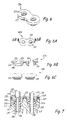
- FIG. 1 is a sectional side view of the connector assembly of the present invention
- FIG. 2 is a perspective view of the ferrule
- FIG. 2 a is a first end view of the ferrule
- FIG. 2 b is a sectional view of the ferrule taken along the line B—B of FIG. 2 a;
- FIG. 2 c is a side elevational view of the ferrule
- FIG. 3 is a first perspective view of the collet
- FIG. 4 is a second perspective view of the collet
- FIG. 5 is a sectional side view of a second embodiment of the connector assembly of the present invention.
- FIG. 5 b is an end view of the embodiment of FIG. 5 ;
- FIG. 5 c is a sectional view of the connector assembly taken along the line B—B of FIG. 6 b;
- FIG. 6 is a perspective view of the double collet
- FIG. 6 a is planar elevational view of the double collet
- FIG. 6 b is a sectional view of the double collet taken along the line B—B of FIG. 6 a;
- FIG. 6 c is a side elevational view of the double collet.
- FIG. 7 is a sectional view of a further embodiment of the connector assembly of the present invention.
- FIG. 8 is a side elevational view of the collet employed with the connector assembly of FIG. 7 ;
- FIG. 9 is a sectional view of the collet of FIG. 8 ;
- FIG. 10 is a perspective view of the ferrule
- FIG. 11 is a sectional view of the ferrule of FIG. 10 ;
- FIG. 12 is a sectional view of the connector assembly.
- the connector assembly of the present invention is shown generally at 10 in the figures.
- the connector assembly 10 is used for permanently connecting a plastic tube 100 to another device.
- a first embodiment of the connector assembly 10 is comprised of ferrule 110 , collet 115 , and connector body 120 , as depicted in FIG. 1 .
- Plastic tubing 100 is defined by proximal end 130 and distal end 140 .
- Plastic tubing 100 comprises tube wall 150 and a hollow lumen 160 .
- the plastic tubing 100 is preferably formed of a pliable, resilient plastic material.
- the ferrule 110 is preferably made of a plastic material, a noted above. Referring to FIGS. 2–2 c , the ferrule 100 has a central bore 111 defined concentric with the longitudinal axis thereof.
- the ferrule 110 has a tubing end 112 and an opposed connector end 113 .
- the external margin of the ferrule 110 has a flared section 114 extending inward from the tubing end 112 to a first cylindrical section 116 .
- the first cylindrical section 116 is connected by a step to a second cylindrical section 117 .
- the second cylindrical section 117 has a reduced diameter as compared to the diameter of the first cylindrical section 116 .
- the second cylindrical section 117 is connected to a flange 118 , having a diameter that is significantly greater than both of the cylindrical sections 116 , 117 .
- a very slightly tapered section 119 extends from the flange 118 to the connector end 113 of the ferrule 110 .
- a seal 140 may be placed on the tapered section 119 and abutted to the flange 118 , as depicted in FIG. 1 .
- the seal 140 may be an elastomeric O-ring.
- the collet 115 is also preferably formed of a plastic material as noted above and is generally ring shaped. More specifically, the collet 115 has an axial bore 121 defined therethrough. The bore 121 has a flared entrance 122 . The flared entrance 122 is coupled to a short, generally cylindrical first section 123 . The first section terminates in a shallow step 124 . The step 124 is connected to a second section 125 that is also generally cylindrical and has a slightly greater diameter than the first section 123 .
- the collet end margin 127 is generally planar, but has a circular energy director 126 formed thereon that may be triangular in cross section, having an elevated peak.
- FIG. 1 depicts the connector body 120 .
- the connector body 120 is preferably made of a plastic material as noted above and may b formed integral to a device to which it is desired to connect the tube 100 , such as, for example, the manifold of a filter assembly.
- the connector body 120 may as well be operably coupled to such device by bonding thereto or otherwise connecting thereto.
- the connector body 120 has a central longitudinal bore 130 .
- the bore 130 has a generally cylindrical section 131 coupled to the distal end 129 of the connector body 120 .
- Bore section 131 terminates at step 132 connected to generally cylindrical section 133 .
- Section 133 has a greater diameter than section 131 .
- Bore section 133 terminates at step 134 connected to generally cylindrical section 135 .
- Section 135 has a greater diameter than section 133 .
- Section 135 flares outward at flared section 136 to proximal end 138 of the connector body 120 .
- the proximal end 138 is generally planar and may have a textured surface to promote the bonding thereof.
- the ferrule 110 with the seal 140 in place is inserted into the bore 130 of the connector body 120 .
- the seal is preferably radially compressed between the exterior margin of the ferrule and the bore section 135 of the bore 130 .
- the flange 118 does not necessarily, but may sealingly compress the seal 140 between the flange 118 and the step 134 and bore section 135 of the connector body 120 .
- the proximal end 130 of the tubing 100 is slid over the taper 114 .
- the taper 114 expands the tubing 100 radially outward.
- the tubing 100 is forced leftward, as depicted in FIG. 1 , until the proximal end 130 abuts the side margin of the flange 118 .
- the resilient tubing 100 contracts to its original shape after passing over the taper 114 into contact with the second cylindrical section 117 .
- a leftward directed biasing force is applied to both the plastic tubing 100 and the collet 115 .
- the collet 115 is forced leftward by a compression device, comprising a piston or similar force applicator.
- the energy director 126 is forced into contact with the preferably textured proximal end 138 of the connector body 120 .
- the shallow step 124 compressively engages the tubing 100 and forms a narrow neck in cooperation with the surface 116 of the ferrule 110 , thereby capturing the portion of the tubing 100 that has contracted around the cylindrical surface 117 .
- the user While maintaining intimate contact between the collet 115 and the connector body 120 , the user activates an ultrasonic generator (not shown). Activating the ultrasonic generator causes the interface between the collet 115 and the connector body 120 at surfaces 127 , 138 to be heated. Heating is enhanced by the energy director 126 being forced into contact with the preferably textured proximal end 138 of the connector body 120 . The heating efficiently softens and deforms the energy director 126 and promotes efficient bonding with the preferably textured proximal end 138 .
- the heat in cooperation with the leftward directed force on the tubing 100 further causes the proximal end of the tubing 100 to soften and to further fill the void defined adjacent to the flare 114 by the cylindrical surface 117 and the flange 118 of the ferrule 110 , and the cylindrical surface 125 of the collet 115 .
- the application of heat by the ultrasonic energy causes melting proximate surfaces 127 , 138 and subsequent cooling substantially permanently bonds the collet 115 to the connector body 120 and substantially permanently and mechanically captures the tubing 110 between the collet 115 and the ferrule 110 .
- the tubing 100 may not be withdrawn with any reasonable force application. This is a mechanical tube connection with no chemical connection between the tube 100 and ferrule 110 , collet 115 , and/or connector body 120 .
- FIGS. 5 and 6 depict a further embodiment of the present invention useful for simultaneously joining two tubes 100 to a connector body 120 a .
- the collet 115 a and the connector body 120 a are formed with dual receptacles for a pair of tubes 100 .
- the two ferrules 110 are formed identical to the ferrules 110 noted above.
- the various features of the collet 115 a and the connector body 120 a are as noted above with respect to the single tube 100 embodiment. Operation to effect the joining of the pair of tubes 100 to the connector body 120 a is the same as noted above with respect to joining a single tube 100 to the connector body 120 .
- the advantage of this embodiment is the elimination of a joining procedure where two tubes 100 are used in close proximity.
- FIGS. 7–12 A further embodiment of the present invention is depicted in FIGS. 7–12 .
- the connector assembly 10 of FIGS. 7–11 includes numerals identifying a common assembly component that are the same as the numerals noted above.
- ferrule 110 depicted in FIGS. 7 , 10 and 11 , is virtually identical to the ferrule 110 described above.
- the collet 115 b differs in certain respect from the collets 115 and 115 a noted above.
- the collet 115 b has a generally planar end margin 127 .
- the end margin 127 has a relatively rough surface.
- a circular scavenger groove 128 is defined in the end margin 127 .
- the bore 121 of collet 115 b includes an indent 126 .
- the indent 126 is generally opposite the flared section 114 and adjacent cylindrical section 116 of the ferrule 110 .
- the space between the indent 126 and the flared section 114 and first cylindrical section 116 defines a generally expanded path through which the plastic tube 100 must pass, the path contracted downstream of the expansion.
- the collet 115 b has a pair of hexagonal margins 140 that define a portion of the exterior margin of the collet 115 b .
- a respective hexagonal margin 140 is concentric with a respective bore 121 defined in the collet 115 b.
- the connector body 120 depicted in FIG. 7 includes a hexagonal bore portion 136 a that forms an end portion of the bore 130 .
- the tube connection is effected as noted above.
- a force is exerted upon the collet 115 b at the same time that sonic energy is applied.
- the roughness of the surfaces 127 , 138 promotes melting at the interface of the surfaces 127 , 138 .
- This melting in conjunction with the force exerted on the collet 115 b causes the collet to move closer to the connector body 120 about 0.050 inches.
- Melt that is generated at the interface of the surfaces 127 , 138 then flows into the scavenger groove 128 .
- Subsequent cooling causes bonding between the collet 115 b and the connector body at the interface of the surfaces 127 , 138 and by means of the melted material exposed within the scavenger groove 128 . In this manner, the plastic tube 100 is mechanically captured between the ferrule 110 and collet 115 b.
Abstract
Description
Claims (19)
Priority Applications (8)
| Application Number | Priority Date | Filing Date | Title |
|---|---|---|---|
| US10/412,050 US7156423B2 (en) | 2003-04-11 | 2003-04-11 | Plastic tube joint |
| AU2004230594A AU2004230594A1 (en) | 2003-04-11 | 2004-04-09 | Plastic tube joint |
| MXPA05010877A MXPA05010877A (en) | 2003-04-11 | 2004-04-09 | Plastic tube joint. |
| PCT/US2004/010923 WO2004092631A2 (en) | 2003-04-11 | 2004-04-09 | Plastic tube joint |
| EP04759321A EP1613887B1 (en) | 2003-04-11 | 2004-04-09 | Plastic tube joint |
| BRPI0409756-4A BRPI0409756A (en) | 2003-04-11 | 2004-04-09 | plastic pipe connector unit and method for simultaneously forming a plastic pipe joint in a pair of plastic pipes |
| JP2006509839A JP4624345B2 (en) | 2003-04-11 | 2004-04-09 | Plastic pipe fittings |
| CN2004800096969A CN1774595B (en) | 2003-04-11 | 2004-04-09 | Plastic tube joint |
Applications Claiming Priority (1)
| Application Number | Priority Date | Filing Date | Title |
|---|---|---|---|
| US10/412,050 US7156423B2 (en) | 2003-04-11 | 2003-04-11 | Plastic tube joint |
Publications (2)
| Publication Number | Publication Date |
|---|---|
| US20040201212A1 US20040201212A1 (en) | 2004-10-14 |
| US7156423B2 true US7156423B2 (en) | 2007-01-02 |
Family
ID=33131138
Family Applications (1)
| Application Number | Title | Priority Date | Filing Date |
|---|---|---|---|
| US10/412,050 Expired - Lifetime US7156423B2 (en) | 2003-04-11 | 2003-04-11 | Plastic tube joint |
Country Status (8)
| Country | Link |
|---|---|
| US (1) | US7156423B2 (en) |
| EP (1) | EP1613887B1 (en) |
| JP (1) | JP4624345B2 (en) |
| CN (1) | CN1774595B (en) |
| AU (1) | AU2004230594A1 (en) |
| BR (1) | BRPI0409756A (en) |
| MX (1) | MXPA05010877A (en) |
| WO (1) | WO2004092631A2 (en) |
Cited By (4)
| Publication number | Priority date | Publication date | Assignee | Title |
|---|---|---|---|---|
| US20070107707A1 (en) * | 2005-11-16 | 2007-05-17 | Arnulf Spieth | Crosstalk device for an exhaust system |
| DE102008059087A1 (en) * | 2008-11-26 | 2010-05-27 | Veritas Ag | Conduit for a pressurized fluid and method for its preparation |
| USD639398S1 (en) * | 2006-07-26 | 2011-06-07 | Colder Products Company | Fluid coupling |
| US11585465B2 (en) | 2020-09-03 | 2023-02-21 | Evergreen Innovation Group, LLC | Modular conduit systems with alignment members |
Families Citing this family (9)
| Publication number | Priority date | Publication date | Assignee | Title |
|---|---|---|---|---|
| DE10051606A1 (en) * | 2000-10-18 | 2002-05-02 | Loi Thermprocess Gmbh | Method and device for annealing pipes |
| CN1890520A (en) * | 2003-10-28 | 2007-01-03 | 3M创新有限公司 | Designs for filtration systems within appliances |
| EP1723069B1 (en) | 2004-01-20 | 2013-06-19 | 3M Innovative Properties Company | Water dispenser with water filter for a refrigerator |
| NL1029030C2 (en) * | 2005-05-12 | 2006-11-14 | Actuant Corp | Hydraulic system. |
| US20070236010A1 (en) * | 2006-04-06 | 2007-10-11 | Campau Daniel N | Connector for corrugated conduit |
| JP5351386B2 (en) * | 2006-05-17 | 2013-11-27 | カルソニックカンセイ株式会社 | Heat exchanger piping connector |
| CN102859247B (en) * | 2010-04-22 | 2015-08-05 | 日本皮拉工业株式会社 | The melt-coating method of deposition joint, deposit device, deposition joint |
| US8328448B1 (en) * | 2010-06-09 | 2012-12-11 | Hufnagel Randall S | Hardware hole filling device |
| CN103091504A (en) * | 2011-10-31 | 2013-05-08 | 深圳迈瑞生物医疗电子股份有限公司 | Pipeline adapter assembly, reagent container assembly and sample analyzer |
Citations (82)
| Publication number | Priority date | Publication date | Assignee | Title |
|---|---|---|---|---|
| US2701147A (en) * | 1949-02-26 | 1955-02-01 | Aeromat Products Company Inc | Quick-release conduit connection |
| US3312483A (en) | 1960-08-17 | 1967-04-04 | D And G Plastics Co | Pipe connector |
| US3312484A (en) | 1960-10-31 | 1967-04-04 | D & G Plastics Co | Toggle ring tube coupling |
| US3583710A (en) | 1968-09-20 | 1971-06-08 | Plastic Omnium Sa | Joint for plastic tubes |
| US3669475A (en) | 1970-05-22 | 1972-06-13 | Mueller Co | Compression couplings |
| US3695643A (en) | 1970-05-18 | 1972-10-03 | Hancock Brick & Tile Co | Corrugated tube coupling means |
| US3753575A (en) * | 1971-10-20 | 1973-08-21 | Cornelius Co | Fluid coupling assembly |
| US3873132A (en) * | 1974-02-19 | 1975-03-25 | American Flange & Mfg | Plastic container closure flange |
| US3874709A (en) | 1972-09-18 | 1975-04-01 | Cardinal Of Adrian | Tubing fitting |
| US3884513A (en) | 1973-01-31 | 1975-05-20 | Legris France Sa | Coupling for a pipe or tube |
| US3893716A (en) | 1974-04-01 | 1975-07-08 | Weatherhead Co | Flareless fitting |
| US3909046A (en) | 1973-04-24 | 1975-09-30 | Legris France Sa | Connector for fluid conduits, such as semi-rigid pipes |
| US3929359A (en) | 1974-11-04 | 1975-12-30 | Hancock Brick & Tile Co | Connecting joint structure for corrugated plastic tubing |
| US3994515A (en) | 1975-11-21 | 1976-11-30 | Cotten Roger C | Joinder of plastic pipe |
| US3999783A (en) | 1973-04-24 | 1976-12-28 | Ste. Legris France S.A. | Connector for fluid conduits, such as semi-rigid pipe |
| US4005883A (en) | 1974-08-05 | 1977-02-01 | Guest John D | Tube couplings |
| US4007951A (en) * | 1973-08-21 | 1977-02-15 | Ste Legris France S.A. | Multi-way connector for hydraulic conduits |
| US4022499A (en) | 1975-04-14 | 1977-05-10 | Aeroquip Corporation | Tube retaining compression fitting |
| US4037864A (en) | 1975-04-14 | 1977-07-26 | Emco Ltd. | Pipe coupling |
| US4049034A (en) * | 1976-07-14 | 1977-09-20 | Baxter Travenol Laboratories, Inc. | Attaching means and method for attaching flexible tubing to a plastic container |
| US4072328A (en) | 1976-05-25 | 1978-02-07 | Hepworth Plastics Limited | Pipe couplings |
| US4123090A (en) | 1976-07-19 | 1978-10-31 | Imperial-Eastman Corporation | Push-pull fitting |
| US4146254A (en) | 1976-03-31 | 1979-03-27 | Bristol Products, Inc. | Coupler for tubing |
| US4178023A (en) | 1977-02-09 | 1979-12-11 | Guest John D | Couplings for tubes |
| US4220361A (en) | 1979-02-01 | 1980-09-02 | The Aro Corporation | Connector for plastic tubing |
| US4298220A (en) | 1978-04-29 | 1981-11-03 | Shoketsu Kinzoku Kogyo Kabushiki Kaisha | Pipe joint |
| US4586734A (en) | 1982-12-08 | 1986-05-06 | General Industries, Inc. | Pipe joint assembly |
| US4606783A (en) | 1982-12-13 | 1986-08-19 | Guest John D | Tube couplings |
| US4611832A (en) * | 1983-03-26 | 1986-09-16 | Tokai Rubber Industries Ltd. | Hose joint |
| US4635975A (en) | 1985-09-25 | 1987-01-13 | Jaco Manufacturing Company | Quick-connect tube coupling |
| US4650529A (en) | 1983-07-21 | 1987-03-17 | Guest John D | Quick release tube coupling |
| US4722560A (en) | 1983-07-21 | 1988-02-02 | Guest John D | Quick release tube coupling |
| US4727242A (en) | 1985-10-24 | 1988-02-23 | Glynwed Tubes & Fittings Ltd. | Electrofusion coupler |
| US4802696A (en) | 1986-10-23 | 1989-02-07 | The Gates Rubber Company | Quick connect coupling |
| US4810009A (en) | 1985-04-29 | 1989-03-07 | Legris S.A. | Instantaneous connection device for plastic and metal material tubes |
| US4826218A (en) | 1987-12-10 | 1989-05-02 | Crawford Fitting Co. | Coupling device for heavy-walled tubular members |
| US4836586A (en) | 1975-04-09 | 1989-06-06 | Raychem Corporation | Composite coupling |
| US4869533A (en) | 1986-08-29 | 1989-09-26 | Georg Fischer Ag | Fitting of weldable thermoplastic material |
| US4946213A (en) | 1988-03-25 | 1990-08-07 | Guest John D | Tube couplings |
| US5085472A (en) | 1988-12-16 | 1992-02-04 | John Guest Engineering Limited | Tube coupling sleeves |
| US5150926A (en) | 1990-03-06 | 1992-09-29 | Geberit Ag | Double pipe connection on plastic pipes |
| US5150923A (en) | 1987-06-29 | 1992-09-29 | Hitach Metals, Ltd. | Plastic pipe joint assembly for joining sections of plastic pipe |
| US5230539A (en) | 1991-12-31 | 1993-07-27 | Dana Corporation | Quick connect tube coupling |
| US5292157A (en) | 1991-11-14 | 1994-03-08 | A. Raymond & Cie | Detachable push-in connector for semirigid pipes |
| US5332269A (en) | 1991-02-28 | 1994-07-26 | Hewing Gmbh | Connecting device for plastic tubes and method for connecting a plastic tube |
| US5375889A (en) | 1989-01-11 | 1994-12-27 | Osaka Gas Co., Ltd. | Electrofusion joint and hot water supply header using the same |
| US5462313A (en) * | 1993-10-26 | 1995-10-31 | Form Rite Corporation | Quick connect coupling |
| US5511830A (en) | 1994-09-20 | 1996-04-30 | Dana Corporation | Quick connect tube couplings |
| US5542717A (en) | 1994-01-03 | 1996-08-06 | Form Rite, Corporation | Quick connect coupling |
| US5553901A (en) | 1991-12-26 | 1996-09-10 | Legris S.A. | Device for connecting a length of duct to a coupling endpiece |
| US5564757A (en) | 1994-03-30 | 1996-10-15 | Metalurgica Detroit S.A. | Push-in locking joint for small diameter tubes |
| US5573279A (en) | 1994-01-03 | 1996-11-12 | Form Rite Corporation | Quick connect coupling |
| US5584513A (en) | 1992-03-06 | 1996-12-17 | Parker-Hannifin Corporation | Push in plastic tube fitting |
| US5593186A (en) | 1993-07-20 | 1997-01-14 | Philmac Pty Ltd | Coupling for outer surface engagement of polymeric pipe |
| US5603530A (en) | 1994-09-14 | 1997-02-18 | Guest; John D. | Grab rings |
| US5607193A (en) | 1994-01-13 | 1997-03-04 | Guest; John D. | Tube couplings |
| US5683120A (en) | 1996-06-03 | 1997-11-04 | Parker-Hannifin Corporation | Releasable push-to-connect tube fitting |
| US5772263A (en) | 1996-12-20 | 1998-06-30 | Itt Automotive, Inc. | One piece quick connector and integral retainer |
| US5775742A (en) | 1995-07-28 | 1998-07-07 | Guest; John Derek | Tube couplings |
| US5779284A (en) | 1995-06-26 | 1998-07-14 | Guest; John Derek | Tube coupling bodies having resilient fingers spaced from the groove wall |
| US5873610A (en) | 1996-12-19 | 1999-02-23 | Itt Automotive, Inc. | Female connector member for large tolerance male member endforms |
| US5887911A (en) | 1995-10-13 | 1999-03-30 | Form Rite | Quick connect fluid coupling with a self-contained releasable collet retainer |
| US5909902A (en) | 1994-03-24 | 1999-06-08 | Metalurgica Detroit S.A. | Insert for locking a tube in a connection body |
| US6056326A (en) | 1998-03-27 | 2000-05-02 | Guest; John Derek | Tube couplings |
| US6065779A (en) | 1997-08-13 | 2000-05-23 | Parker-Hannifin Corporation | Clip for releasable push-to-connect tube fittings |
| US6118108A (en) | 1999-06-09 | 2000-09-12 | A. O. Smith Corporation | Heating method and apparatus to accelerate flanged joint adhesive cure |
| US6145894A (en) | 1998-10-16 | 2000-11-14 | Bridgestone/Firestone, Inc. | Push-pull connector and air spring-combination |
| US6149206A (en) | 1998-06-15 | 2000-11-21 | Dresser Industries, Inc. | Fluid distribution apparatus and method |
| US6173999B1 (en) | 1998-07-29 | 2001-01-16 | John Derek Guest | Tube coupling devices |
| US6183022B1 (en) | 1995-06-26 | 2001-02-06 | John Derek Guest | Tube coupling bodies |
| US6217084B1 (en) | 1996-11-21 | 2001-04-17 | Dresser Wayne Aktiebolag | Device on a conduit end and arrangement for joining conduits |
| US6224117B1 (en) | 1998-10-05 | 2001-05-01 | Dana Corporation | Contaminant resistant tube fitting |
| US6264250B1 (en) | 1997-11-10 | 2001-07-24 | Solar Giken Co., Ltd. | Tube joint |
| US6267416B1 (en) | 1996-10-07 | 2001-07-31 | Rea International, Inc. | Connector assembly for axial loads |
| US6276728B1 (en) | 1999-07-08 | 2001-08-21 | Omega Flex, Inc. | Fitting for use with corrugated tubing |
| US6302451B1 (en) | 2000-03-15 | 2001-10-16 | Dana Corporation | Quick-connect hose end couplings |
| US6312019B1 (en) | 1999-08-03 | 2001-11-06 | Smc Corporation | Pipe joint |
| US6334634B1 (en) | 2000-06-20 | 2002-01-01 | International Truck And Engine Corporation | Push-to-connect tubing fitting |
| US6347815B1 (en) | 1995-08-31 | 2002-02-19 | Cooper Technology Services, Llc | Quick connect fluid coupling with components positioned to provide continuous insertion resistance |
| US6390511B1 (en) | 1995-10-13 | 2002-05-21 | Cooperstandard Automotive, Inc. | Quick connect fluid coupling with collet retainer |
| US6464266B1 (en) | 1998-12-18 | 2002-10-15 | Accor Technology, Inc. | Tube coupling |
| US6517124B1 (en) | 1999-09-27 | 2003-02-11 | Legris S.A. | Device for connecting a pipe end to a member |
Family Cites Families (5)
| Publication number | Priority date | Publication date | Assignee | Title |
|---|---|---|---|---|
| FR2595434B1 (en) * | 1986-03-07 | 1988-06-10 | Pont A Mousson | JUNCTION DEVICE BETWEEN PIPES COMPRISING A MALE END AND A SOCKET |
| US6264650B1 (en) * | 1995-06-07 | 2001-07-24 | Arthrocare Corporation | Methods for electrosurgical treatment of intervertebral discs |
| CA2319378A1 (en) * | 1998-02-09 | 1999-08-12 | Linkindex Limited | Hose connector and threaded collar therefor |
| US6953526B1 (en) * | 2000-03-22 | 2005-10-11 | Cuno Incorporated | Filter assembly |
| JP3442723B2 (en) * | 2000-06-19 | 2003-09-02 | 日本ピラー工業株式会社 | Multi-channel rotary joint |
-
2003
- 2003-04-11 US US10/412,050 patent/US7156423B2/en not_active Expired - Lifetime
-
2004
- 2004-04-09 JP JP2006509839A patent/JP4624345B2/en not_active Expired - Fee Related
- 2004-04-09 MX MXPA05010877A patent/MXPA05010877A/en not_active Application Discontinuation
- 2004-04-09 WO PCT/US2004/010923 patent/WO2004092631A2/en active Application Filing
- 2004-04-09 CN CN2004800096969A patent/CN1774595B/en not_active Expired - Lifetime
- 2004-04-09 EP EP04759321A patent/EP1613887B1/en not_active Expired - Lifetime
- 2004-04-09 BR BRPI0409756-4A patent/BRPI0409756A/en not_active IP Right Cessation
- 2004-04-09 AU AU2004230594A patent/AU2004230594A1/en not_active Abandoned
Patent Citations (82)
| Publication number | Priority date | Publication date | Assignee | Title |
|---|---|---|---|---|
| US2701147A (en) * | 1949-02-26 | 1955-02-01 | Aeromat Products Company Inc | Quick-release conduit connection |
| US3312483A (en) | 1960-08-17 | 1967-04-04 | D And G Plastics Co | Pipe connector |
| US3312484A (en) | 1960-10-31 | 1967-04-04 | D & G Plastics Co | Toggle ring tube coupling |
| US3583710A (en) | 1968-09-20 | 1971-06-08 | Plastic Omnium Sa | Joint for plastic tubes |
| US3695643A (en) | 1970-05-18 | 1972-10-03 | Hancock Brick & Tile Co | Corrugated tube coupling means |
| US3669475A (en) | 1970-05-22 | 1972-06-13 | Mueller Co | Compression couplings |
| US3753575A (en) * | 1971-10-20 | 1973-08-21 | Cornelius Co | Fluid coupling assembly |
| US3874709A (en) | 1972-09-18 | 1975-04-01 | Cardinal Of Adrian | Tubing fitting |
| US3884513A (en) | 1973-01-31 | 1975-05-20 | Legris France Sa | Coupling for a pipe or tube |
| US3999783A (en) | 1973-04-24 | 1976-12-28 | Ste. Legris France S.A. | Connector for fluid conduits, such as semi-rigid pipe |
| US3909046A (en) | 1973-04-24 | 1975-09-30 | Legris France Sa | Connector for fluid conduits, such as semi-rigid pipes |
| US4007951A (en) * | 1973-08-21 | 1977-02-15 | Ste Legris France S.A. | Multi-way connector for hydraulic conduits |
| US3873132A (en) * | 1974-02-19 | 1975-03-25 | American Flange & Mfg | Plastic container closure flange |
| US3893716A (en) | 1974-04-01 | 1975-07-08 | Weatherhead Co | Flareless fitting |
| US4005883A (en) | 1974-08-05 | 1977-02-01 | Guest John D | Tube couplings |
| US3929359A (en) | 1974-11-04 | 1975-12-30 | Hancock Brick & Tile Co | Connecting joint structure for corrugated plastic tubing |
| US4836586A (en) | 1975-04-09 | 1989-06-06 | Raychem Corporation | Composite coupling |
| US4022499A (en) | 1975-04-14 | 1977-05-10 | Aeroquip Corporation | Tube retaining compression fitting |
| US4037864A (en) | 1975-04-14 | 1977-07-26 | Emco Ltd. | Pipe coupling |
| US3994515A (en) | 1975-11-21 | 1976-11-30 | Cotten Roger C | Joinder of plastic pipe |
| US4146254A (en) | 1976-03-31 | 1979-03-27 | Bristol Products, Inc. | Coupler for tubing |
| US4072328A (en) | 1976-05-25 | 1978-02-07 | Hepworth Plastics Limited | Pipe couplings |
| US4049034A (en) * | 1976-07-14 | 1977-09-20 | Baxter Travenol Laboratories, Inc. | Attaching means and method for attaching flexible tubing to a plastic container |
| US4123090A (en) | 1976-07-19 | 1978-10-31 | Imperial-Eastman Corporation | Push-pull fitting |
| US4178023A (en) | 1977-02-09 | 1979-12-11 | Guest John D | Couplings for tubes |
| US4298220A (en) | 1978-04-29 | 1981-11-03 | Shoketsu Kinzoku Kogyo Kabushiki Kaisha | Pipe joint |
| US4220361A (en) | 1979-02-01 | 1980-09-02 | The Aro Corporation | Connector for plastic tubing |
| US4586734A (en) | 1982-12-08 | 1986-05-06 | General Industries, Inc. | Pipe joint assembly |
| US4606783A (en) | 1982-12-13 | 1986-08-19 | Guest John D | Tube couplings |
| US4611832A (en) * | 1983-03-26 | 1986-09-16 | Tokai Rubber Industries Ltd. | Hose joint |
| US4650529A (en) | 1983-07-21 | 1987-03-17 | Guest John D | Quick release tube coupling |
| US4722560A (en) | 1983-07-21 | 1988-02-02 | Guest John D | Quick release tube coupling |
| US4810009A (en) | 1985-04-29 | 1989-03-07 | Legris S.A. | Instantaneous connection device for plastic and metal material tubes |
| US4635975A (en) | 1985-09-25 | 1987-01-13 | Jaco Manufacturing Company | Quick-connect tube coupling |
| US4727242A (en) | 1985-10-24 | 1988-02-23 | Glynwed Tubes & Fittings Ltd. | Electrofusion coupler |
| US4869533A (en) | 1986-08-29 | 1989-09-26 | Georg Fischer Ag | Fitting of weldable thermoplastic material |
| US4802696A (en) | 1986-10-23 | 1989-02-07 | The Gates Rubber Company | Quick connect coupling |
| US5150923A (en) | 1987-06-29 | 1992-09-29 | Hitach Metals, Ltd. | Plastic pipe joint assembly for joining sections of plastic pipe |
| US4826218A (en) | 1987-12-10 | 1989-05-02 | Crawford Fitting Co. | Coupling device for heavy-walled tubular members |
| US4946213A (en) | 1988-03-25 | 1990-08-07 | Guest John D | Tube couplings |
| US5085472A (en) | 1988-12-16 | 1992-02-04 | John Guest Engineering Limited | Tube coupling sleeves |
| US5375889A (en) | 1989-01-11 | 1994-12-27 | Osaka Gas Co., Ltd. | Electrofusion joint and hot water supply header using the same |
| US5150926A (en) | 1990-03-06 | 1992-09-29 | Geberit Ag | Double pipe connection on plastic pipes |
| US5332269A (en) | 1991-02-28 | 1994-07-26 | Hewing Gmbh | Connecting device for plastic tubes and method for connecting a plastic tube |
| US5292157A (en) | 1991-11-14 | 1994-03-08 | A. Raymond & Cie | Detachable push-in connector for semirigid pipes |
| US5553901A (en) | 1991-12-26 | 1996-09-10 | Legris S.A. | Device for connecting a length of duct to a coupling endpiece |
| US5230539A (en) | 1991-12-31 | 1993-07-27 | Dana Corporation | Quick connect tube coupling |
| US5584513A (en) | 1992-03-06 | 1996-12-17 | Parker-Hannifin Corporation | Push in plastic tube fitting |
| US5593186A (en) | 1993-07-20 | 1997-01-14 | Philmac Pty Ltd | Coupling for outer surface engagement of polymeric pipe |
| US5462313A (en) * | 1993-10-26 | 1995-10-31 | Form Rite Corporation | Quick connect coupling |
| US5573279A (en) | 1994-01-03 | 1996-11-12 | Form Rite Corporation | Quick connect coupling |
| US5542717A (en) | 1994-01-03 | 1996-08-06 | Form Rite, Corporation | Quick connect coupling |
| US5607193A (en) | 1994-01-13 | 1997-03-04 | Guest; John D. | Tube couplings |
| US5909902A (en) | 1994-03-24 | 1999-06-08 | Metalurgica Detroit S.A. | Insert for locking a tube in a connection body |
| US5564757A (en) | 1994-03-30 | 1996-10-15 | Metalurgica Detroit S.A. | Push-in locking joint for small diameter tubes |
| US5603530A (en) | 1994-09-14 | 1997-02-18 | Guest; John D. | Grab rings |
| US5511830A (en) | 1994-09-20 | 1996-04-30 | Dana Corporation | Quick connect tube couplings |
| US6183022B1 (en) | 1995-06-26 | 2001-02-06 | John Derek Guest | Tube coupling bodies |
| US5779284A (en) | 1995-06-26 | 1998-07-14 | Guest; John Derek | Tube coupling bodies having resilient fingers spaced from the groove wall |
| US5775742A (en) | 1995-07-28 | 1998-07-07 | Guest; John Derek | Tube couplings |
| US6347815B1 (en) | 1995-08-31 | 2002-02-19 | Cooper Technology Services, Llc | Quick connect fluid coupling with components positioned to provide continuous insertion resistance |
| US5887911A (en) | 1995-10-13 | 1999-03-30 | Form Rite | Quick connect fluid coupling with a self-contained releasable collet retainer |
| US6390511B1 (en) | 1995-10-13 | 2002-05-21 | Cooperstandard Automotive, Inc. | Quick connect fluid coupling with collet retainer |
| US5683120A (en) | 1996-06-03 | 1997-11-04 | Parker-Hannifin Corporation | Releasable push-to-connect tube fitting |
| US6267416B1 (en) | 1996-10-07 | 2001-07-31 | Rea International, Inc. | Connector assembly for axial loads |
| US6217084B1 (en) | 1996-11-21 | 2001-04-17 | Dresser Wayne Aktiebolag | Device on a conduit end and arrangement for joining conduits |
| US5873610A (en) | 1996-12-19 | 1999-02-23 | Itt Automotive, Inc. | Female connector member for large tolerance male member endforms |
| US5772263A (en) | 1996-12-20 | 1998-06-30 | Itt Automotive, Inc. | One piece quick connector and integral retainer |
| US6065779A (en) | 1997-08-13 | 2000-05-23 | Parker-Hannifin Corporation | Clip for releasable push-to-connect tube fittings |
| US6264250B1 (en) | 1997-11-10 | 2001-07-24 | Solar Giken Co., Ltd. | Tube joint |
| US6056326A (en) | 1998-03-27 | 2000-05-02 | Guest; John Derek | Tube couplings |
| US6149206A (en) | 1998-06-15 | 2000-11-21 | Dresser Industries, Inc. | Fluid distribution apparatus and method |
| US6173999B1 (en) | 1998-07-29 | 2001-01-16 | John Derek Guest | Tube coupling devices |
| US6224117B1 (en) | 1998-10-05 | 2001-05-01 | Dana Corporation | Contaminant resistant tube fitting |
| US6145894A (en) | 1998-10-16 | 2000-11-14 | Bridgestone/Firestone, Inc. | Push-pull connector and air spring-combination |
| US6464266B1 (en) | 1998-12-18 | 2002-10-15 | Accor Technology, Inc. | Tube coupling |
| US6118108A (en) | 1999-06-09 | 2000-09-12 | A. O. Smith Corporation | Heating method and apparatus to accelerate flanged joint adhesive cure |
| US6276728B1 (en) | 1999-07-08 | 2001-08-21 | Omega Flex, Inc. | Fitting for use with corrugated tubing |
| US6312019B1 (en) | 1999-08-03 | 2001-11-06 | Smc Corporation | Pipe joint |
| US6517124B1 (en) | 1999-09-27 | 2003-02-11 | Legris S.A. | Device for connecting a pipe end to a member |
| US6302451B1 (en) | 2000-03-15 | 2001-10-16 | Dana Corporation | Quick-connect hose end couplings |
| US6334634B1 (en) | 2000-06-20 | 2002-01-01 | International Truck And Engine Corporation | Push-to-connect tubing fitting |
Cited By (7)
| Publication number | Priority date | Publication date | Assignee | Title |
|---|---|---|---|---|
| US20070107707A1 (en) * | 2005-11-16 | 2007-05-17 | Arnulf Spieth | Crosstalk device for an exhaust system |
| US7866709B2 (en) * | 2005-11-16 | 2011-01-11 | J. Eberspaecher Gmbh & Co. Kg | Crosstalk device for an exhaust system |
| USD639398S1 (en) * | 2006-07-26 | 2011-06-07 | Colder Products Company | Fluid coupling |
| DE102008059087A1 (en) * | 2008-11-26 | 2010-05-27 | Veritas Ag | Conduit for a pressurized fluid and method for its preparation |
| US20100126303A1 (en) * | 2008-11-26 | 2010-05-27 | Mai Sven | Conduit arrangement for a pressurized fluid, and method for the production thereof |
| US8388027B2 (en) | 2008-11-26 | 2013-03-05 | Veritas Ag | Conduit arrangement for a pressurized fluid, and method for the production thereof |
| US11585465B2 (en) | 2020-09-03 | 2023-02-21 | Evergreen Innovation Group, LLC | Modular conduit systems with alignment members |
Also Published As
| Publication number | Publication date |
|---|---|
| JP4624345B2 (en) | 2011-02-02 |
| US20040201212A1 (en) | 2004-10-14 |
| MXPA05010877A (en) | 2007-06-08 |
| WO2004092631A2 (en) | 2004-10-28 |
| EP1613887B1 (en) | 2011-06-08 |
| CN1774595A (en) | 2006-05-17 |
| WO2004092631A3 (en) | 2005-02-17 |
| CN1774595B (en) | 2012-04-11 |
| EP1613887A2 (en) | 2006-01-11 |
| JP2006522909A (en) | 2006-10-05 |
| EP1613887A4 (en) | 2007-11-14 |
| AU2004230594A1 (en) | 2004-10-28 |
| BRPI0409756A (en) | 2006-05-09 |
Similar Documents
| Publication | Publication Date | Title |
|---|---|---|
| US20040021318A1 (en) | Tubing attachment | |
| US6857670B2 (en) | Plastic tube joint | |
| US7156423B2 (en) | Plastic tube joint | |
| US4896904A (en) | Heat shrinkable device with adhesive barrier for connecting elongate objects | |
| CN106461130A (en) | Resin-made tube joint | |
| TW201100684A (en) | Fluid fitting | |
| US6412832B1 (en) | Self-flaring plastic fittings | |
| US6843512B2 (en) | Tubing connector | |
| US10281077B2 (en) | Fusion welding fittings with weld bead cover | |
| CN101245883B (en) | A coupling system for polymeric pipes | |
| CN109506034B (en) | Waterway assembly of faucet and method for manufacturing waterway assembly | |
| US20030192641A1 (en) | Method and apparatus of assembling a fluid flow conduit assembly of dissimilar plastics | |
| US5984377A (en) | Bondable plastic piping adapter joint | |
| CN216319219U (en) | Connection assembly for intravenous component and infusion device assembly comprising same | |
| CN100429448C (en) | Heat melting assembling connector for pipeline | |
| CN2851792Y (en) | Hot-melt assembling connector for pipeline | |
| CN111684163A (en) | Device for establishing a connection of a pipe system and method for using the same | |
| NZ196298A (en) | Joining plastics pipes by forced insertion | |
| RU185099U1 (en) | TAP-FREE PIPE FITTING | |
| GB2197408A (en) | Device for connecting elongate objects | |
| JPH0478396A (en) | Joint tube and manufacture thereof | |
| JPS60116992A (en) | Instrument and method for connection |
Legal Events
| Date | Code | Title | Description |
|---|---|---|---|
| AS | Assignment |
Owner name: PENTAPURE INCORPORATED, MINNESOTA Free format text: ASSIGNMENT OF ASSIGNORS INTEREST;ASSIGNOR:MARKS, NATHAN;REEL/FRAME:013966/0053 Effective date: 20030409 |
|
| AS | Assignment |
Owner name: CUNO ENGINEERED PRODUCTS, INC., MINNESOTA Free format text: CHANGE OF NAME;ASSIGNOR:PENTAPURE INCORPORATED;REEL/FRAME:015334/0750 Effective date: 20040917 |
|
| AS | Assignment |
Owner name: CUNO INCORPORATED, CONNECTICUT Free format text: ASSIGNMENT OF ASSIGNORS INTEREST;ASSIGNOR:CUNO ENGINEERED PRODUCTS, INC.;REEL/FRAME:015377/0553 Effective date: 20041116 |
|
| AS | Assignment |
Owner name: 3M INNOVATIVE PROPERTIES COMPANY, MINNESOTA Free format text: ASSIGNMENT OF ASSIGNORS INTEREST;ASSIGNOR:CUNO, INCORPORATED, A CORPORATION OF THE STATE OF DELAWARE;REEL/FRAME:017368/0235 Effective date: 20060301 |
|
| STCF | Information on status: patent grant |
Free format text: PATENTED CASE |
|
| CC | Certificate of correction | ||
| FPAY | Fee payment |
Year of fee payment: 4 |
|
| FPAY | Fee payment |
Year of fee payment: 8 |
|
| MAFP | Maintenance fee payment |
Free format text: PAYMENT OF MAINTENANCE FEE, 12TH YEAR, LARGE ENTITY (ORIGINAL EVENT CODE: M1553) Year of fee payment: 12 |