US7158671B2 - Image processing apparatus and method - Google Patents
Image processing apparatus and method Download PDFInfo
- Publication number
- US7158671B2 US7158671B2 US10/391,579 US39157903A US7158671B2 US 7158671 B2 US7158671 B2 US 7158671B2 US 39157903 A US39157903 A US 39157903A US 7158671 B2 US7158671 B2 US 7158671B2
- Authority
- US
- United States
- Prior art keywords
- highlight
- color
- image
- shadow points
- correction
- Prior art date
- Legal status (The legal status is an assumption and is not a legal conclusion. Google has not performed a legal analysis and makes no representation as to the accuracy of the status listed.)
- Expired - Fee Related, expires
Links
Images


Classifications
-
- H—ELECTRICITY
- H04—ELECTRIC COMMUNICATION TECHNIQUE
- H04N—PICTORIAL COMMUNICATION, e.g. TELEVISION
- H04N1/00—Scanning, transmission or reproduction of documents or the like, e.g. facsimile transmission; Details thereof
- H04N1/46—Colour picture communication systems
- H04N1/56—Processing of colour picture signals
- H04N1/60—Colour correction or control
- H04N1/6075—Corrections to the hue
-
- H—ELECTRICITY
- H04—ELECTRIC COMMUNICATION TECHNIQUE
- H04N—PICTORIAL COMMUNICATION, e.g. TELEVISION
- H04N1/00—Scanning, transmission or reproduction of documents or the like, e.g. facsimile transmission; Details thereof
- H04N1/46—Colour picture communication systems
- H04N1/56—Processing of colour picture signals
- H04N1/60—Colour correction or control
- H04N1/6077—Colour balance, e.g. colour cast correction
Definitions
- This invention relates to an image processing apparatus and method and, more particularly, to color correction of an image.
- Digital image input devices such as digital still cameras and scanners have become very popular in recent years, and image output devices typified by ink-jet printers also have been improved in resolution and lowered in cost. This has led to an environment in which a user can print images at home. Meanwhile, many techniques relating to image correction have been proposed and improved.
- the present invention seeks to solve the foregoing problems individually and collectively and its object is to enable suppression of a correction in a specific color direction.
- the foregoing object is attained by providing an image processing method comprising the steps of; detecting highlight and shadow points based upon a histogram of an image; acquiring a hue angle from average color difference information of image data having luminance levels of the highlight and shadow points; revising color information of the highlight and shadow points by adjusting the average color difference information based upon the hue angle; and correcting the image based upon the revised color information of the highlight and shadow points.
- FIG. 1 is a flowchart illustrating an example of image correction processing according to a first embodiment of the present invention
- FIG. 2 is a diagram schematically illustrating the concept of a color correction
- FIG. 3 is a graph useful in describing a gain value for suppressing a correction quantity
- FIG. 4 is a graph useful in describing a plot of correction-quantity suppression gain value vs. luminance
- FIG. 5 is a flowchart illustrating an example of image correction processing according to a second embodiment of the present invention.
- FIG. 6 is a graph useful in describing a plot of correction-quantity suppression gain value vs. luminance that takes halftones into consideration.
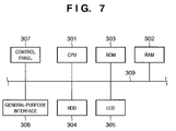
- FIG. 7 is a block diagram illustrating an example of the structure of an image processing apparatus.
- the image processing described below is executed by supplying an image processing program to a computer such as a personal computer of the kind illustrated in FIG. 7 .
- Conceivable examples of the software of this image processing program are driver software receiving an image from an image input device or the like, image editing software for editing an image or driver software such as a so-called printer driver for outputting an image to an image output device or the like.
- FIG. 7 is a block diagram illustrating an image processing apparatus according to an embodiment of the present invention. This apparatus is implemented by supplying a general-purpose personal computer with image processing software.
- the CPU 301 uses a RAM 302 as a work memory, executes various programs such as a operating system and application software stored in a ROM 303 or hard-disk drive (HDD) 304 and control the apparatus components, which are connected to a system bus 309 .
- the image processing described below also is executed by the CPU 301 .
- a liquid crystal display (LCD) 305 is a monitor for displaying the status of various processing and results of processing inclusive of a user interface screen, input images and output images.
- a control panel 307 which includes, e.g., a keyboard and a pointing device such as a mouse, allows the user to input commands and data to the image processing apparatus.
- a general-purpose interface 308 is a serial bus such as an USB (Universal Serial Bus) or IEEE 1394, a parallel interface such as an SCSI, GPIB, IEEE 1284 or PC card bus, or a serial interface such as an RS232C or RS422 (or a combination of a plurality of these).
- the general-purpose interface 308 is capable of connecting an input device such as an image scanner, a film scanner, a digital camera or a video camera, and an output device such as a printer.
- interfaces are present between the hard-disk drive 304 and system bus 309 , the LCD 305 and system bus 309 , and the control panel 307 and system bus 309 .
- Execution of the image processing set forth below is not limited to a computer; the processing can be executed in an image input device or image output device. If an image input device such as a digital camera and an image output device such as an ink-jet printer are connected directly and an image captured by the digital camera is printed, the image processing described below would be executed by the image input device or image output device.
- FIG. 1 is a flowchart illustrating an example of image correction processing according to this embodiment.
- Image correction involves analyzing a histogram of an original image (S 101 ), deciding a highlight point (a point that should be white) and a shadow point (a point that should be black) based upon result of analysis (S 101 ) and then correcting the image.
- the Inventors have disclosed a method of performing an image correction based upon highlight and shadow points (see the specification of Japanese Patent Application Laid-Open No. 2000-13626).
- the concept of the correction disclosed in the above specification is to convert the RGB signal of an original image to a luminance signal Y and two color difference signals C 1 , C 2 , decide a highlight point (Y HL , C 1 HL , C 2 HL ) and shadow point (Y SD , C 1 SD , C 2 SD ) from a histogram function relating to the luminance signal, and perform a color correction in YCC color space (a color space comprising luminance and color difference) in such a manner that these points become white and black, respectively.
- FIG. 2 is a diagram schematically illustrating the concept of this color correction. Here a color solid is mapped in such a manner that a highlight point HL and shadow point SD of the color solid before correction will be situated at white W and black B, respectively.
- a correction of color balance is carried out by a color difference signal between the highlight and shadow points. That is, color fogging of the overall image is corrected by causing the axis from the shadow point to the highlight point to agree with the luminance axis Y.
- this may be considered as performing a conversion of the RGB signal of an image to luminance Y and two color difference signals C 1 , C 2 , defining a color mapping (F) within YCC color space and carrying out a color correction based upon the color conversion and mapping. More specifically, a color correction is performed by Equation (1) below, and image correction is performed upon effecting a restoration to RGB.
- Equation (1) Equation (1) below, and image correction is performed upon effecting a restoration to RGB.
- an image such as a so-called “sunset scene”) that should not undergo a color fogging correction is not subjected to this correction.
- a decision (S 103 ) regarding exception processing which executes a scene-related decision, utilizing the highlight point and various parameters.
- an image that has not been excluded by the exception processing decision (S 103 ) namely an image for which correction has been decided, is subjected to the image correction indiscriminately in accordance with the highlight and shadow points obtained.
- the hues H of a highlight point and shadow point obtained by analysis are found, and if the color direction is one for which a correction is desired to be suppressed, then the highlight and shadow points are revised (S 104 ) by applying a suppression gain to each of the color difference signals.
- a suppression gain value G (0 ⁇ G ⁇ 1) of a correction quantity related to hue H is set in advance.
- the suppression gain value G is decided so as to reduce the correction quantity in a case where hue H is in a warm color system and enlarge the correction quantity in a case where hue H is in a cool color system.
- Suppression gain values G(H HL ) and G(H SD ) versus a hue angle H HL of the highlight point and a hue angle H SD of the shadow point, respectively, are found.
- a suppression gain function relating to hue H may be decided in advance and the suppression gain value G may be calculated based upon this function, or the suppression gain value G corresponding to the hue H may be obtained by referring to a table in which a correction gain function created beforehand is represented in discrete form.
- the suppression gain value G is obtained by referring to a table.
- a reference table is created beforehand in such a manner that the suppression gain value G of the correction quantity will be small in case of hue H in the warm color system, and in such a manner that a suppression gain value G close to 1.0 will be obtained so as to apply a correction close to that of the conventional correction in case of hue H in the cool color system.
- the highlight and shadow points are revised as indicated by Equations (2) below.
- the image is corrected (S 105 ) by the above-described method based upon the highlight and shadow points thus revised.
- a correction quantity is suppressed by revising the color difference information of the highlight and shadow points themselves.
- suppression gain conforming to luminance is applied to a color correction revision quantity (amount of movement) based upon mapping F.
- a suppression gain value G conforming to luminance level is set based upon a suppression gain value G (see FIG. 2 ) corresponding to each hue angle H of the highlight and shadow points.
- Suppression gain value G conforming to luminance Y is defined as a linear function that is based upon, e.g., a suppression gain value G(H SD ) of shadow point Y SD and a suppression gain value G(H HL ) of shadow point Y HL a, as depicted in FIG. 4 .
- a clipped value namely 0 or 1.0, is defined as the suppression gain value G.
- the correction quantity of image data having a luminance corresponding to highlight point HL and shadow point SD can be suppressed to the desired correction quantity.
- the above-described suppression gain value G is applied to amount of movement when a color conversion is made based upon the mapping F of color correction. That is, a revised luminance signal Y′′ and color difference signals C 1 ′′, C 2 ′′ are obtained by Equations (3) from the signal values Y, C 1 , C 2 and Y′, C 1 ′, C 2 ′, which are obtained from Equations (1).
- FIG. 5 is a flowchart illustrating an example of image correction processing according to the second embodiment.
- a reference table regarding the suppression gain value G corresponding to Equations (3) is created at step S 204 , and the image is corrected based upon this reference table.
- a correction-quantity suppression gain value G conforming to luminance Y is set based upon the highlight and shadow points.
- focus is centered on the direction of the slope of the axis (referred to as the “luminance axis”) connecting the shadow and highlight points. That is, the focus is on hue.
- revision of the highlight and shadow points is a correction relating to white and black, and the result of the correction is very recognizable.
- the luminance axis indicates the direction and degree of color shift of the overall image, and correcting the color balance of the image is equivalent to erecting the luminance axis. That is, the hue angle (slope) of the luminance axis indicates the correction direction of the image color balance.
- This embodiment takes such a case into consideration and, as shown in FIG. 6 , obtains a correction-quantity suppression gain value G versus a luminance value 128 of a halftone from the hue angle of the luminance axis, and sets a function of the correction-quantity suppression gain value versus luminance Y.
- the revised luminance signal Y′′ and color difference signals C 1 ′′, C 2 ′′ are found from Equations (3) and the image is corrected as described above.
- luminance value 128 is utilized as a representative halftone.
- luminance value 128 it is permissible to utilize a luminance value, which is obtained by histogram analysis, corresponding to an intermediate value or average value.
- correction in a specific color direction can be tuned with ease while use is made of the conventional color correction techniques. That is, with regard to correction of the color of skin, which is one of the memory colors, a correction in the direction of yellow or in the direction of blue in a cool color system can be suppressed with ease. Moreover, color fogging in a cool color system, such as blue fogging, can be corrected effectively in a manner similar to that of the prior art.
- the present invention can be applied to a system constituted by a plurality of devices (e.g., host computer, interface, reader, printer) or to an apparatus comprising a single device (e.g., copying machine, facsimile machine).
- devices e.g., host computer, interface, reader, printer
- apparatus comprising a single device (e.g., copying machine, facsimile machine).
- the object of the present invention can also be achieved by providing a storage medium storing program codes for performing the aforesaid processes to a computer system or apparatus (e.g., a personal computer), reading the program codes, by a CPU or MPU of the computer system or apparatus, from the storage medium, then executing the program.
- a computer system or apparatus e.g., a personal computer
- the program codes read from the storage medium realize the functions according to the embodiments, and the storage medium storing the program codes constitutes the invention.
- the storage medium such as a floppy disk, a hard disk, an optical disk, a magneto-optical disk, CD-ROM, CD-R, a magnetic tape, a non-volatile type memory card, and ROM can be used for providing the program codes.
- the present invention includes a case where an OS (operating system) or the like working on the computer performs a part or entire processes in accordance with designations of the program codes and realizes functions according to the above embodiments.
- the present invention also includes a case where, after the program codes read from the storage medium are written in a function expansion card which is inserted into the computer or in a memory provided in a function expansion unit which is connected to the computer, CPU or the like contained in the function expansion card or unit performs a part or entire process in accordance with designations of the program codes and realizes functions of the above embodiments.
Abstract
Description
(Y′,C1′,C2′)=F(Y,C1,C2) (1)
C1HL ′=G(H HL)×C1HL
C2HL ′=G(H HL)×C2HL
C1SD ′=G(H SD)×C1SD
C2SD ′=G(H SD)×C2SD (2)
Y″=G(Y)×(Y′−Y)+Y
C1′=G(Y)×(C1′−C1)+C1
C2″=G(Y)×(C2′−C2)+C2 (3)
Claims (13)
Applications Claiming Priority (2)
| Application Number | Priority Date | Filing Date | Title |
|---|---|---|---|
| JP2002078924A JP3943973B2 (en) | 2002-03-20 | 2002-03-20 | Image processing apparatus and method |
| JP2002-078924 | 2002-03-20 |
Publications (2)
| Publication Number | Publication Date |
|---|---|
| US20030179926A1 US20030179926A1 (en) | 2003-09-25 |
| US7158671B2 true US7158671B2 (en) | 2007-01-02 |
Family
ID=28035618
Family Applications (1)
| Application Number | Title | Priority Date | Filing Date |
|---|---|---|---|
| US10/391,579 Expired - Fee Related US7158671B2 (en) | 2002-03-20 | 2003-03-20 | Image processing apparatus and method |
Country Status (2)
| Country | Link |
|---|---|
| US (1) | US7158671B2 (en) |
| JP (1) | JP3943973B2 (en) |
Cited By (7)
| Publication number | Priority date | Publication date | Assignee | Title |
|---|---|---|---|---|
| US20060045330A1 (en) * | 2002-09-20 | 2006-03-02 | Vincent Marion | Method of color image processing to eliminate shadows and relections |
| US20070030498A1 (en) * | 2005-08-02 | 2007-02-08 | Canon Kabushiki Kaisha | Color processing method and apparatus |
| US20070104389A1 (en) * | 2005-11-09 | 2007-05-10 | Aepx Animation, Inc. | Detection and manipulation of shadows in an image or series of images |
| US20080252757A1 (en) * | 2007-04-12 | 2008-10-16 | Samsung Electronics Co., Ltd. | Apparatus and method for generating wide color gamut signal in image capturing device |
| US20080260245A1 (en) * | 2007-03-16 | 2008-10-23 | Nikon Corporation | Image processing apparatus, imaging apparatus and recording medium storing image processing program |
| US20080316513A1 (en) * | 2007-06-20 | 2008-12-25 | Canon Kabushiki Kaisha | Color management system |
| US10748246B2 (en) | 2016-12-16 | 2020-08-18 | Canon Kabushiki Kaisha | Image processing method with predetermined bitmap formatting, and image processing apparatus and storage medium therewith |
Families Citing this family (12)
| Publication number | Priority date | Publication date | Assignee | Title |
|---|---|---|---|---|
| JP3921499B2 (en) * | 2001-08-22 | 2007-05-30 | 富士フイルム株式会社 | Color image signal processing method and color image signal processing apparatus using the same |
| US7701489B1 (en) | 2003-05-27 | 2010-04-20 | Apple Inc. | Method and apparatus for color correction |
| US7369699B1 (en) | 2003-08-29 | 2008-05-06 | Apple Inc. | Methods and apparatuses for restoring color and enhancing electronic images |
| JP2005244607A (en) * | 2004-02-26 | 2005-09-08 | Fuji Photo Film Co Ltd | System, device and program for converting color |
| US8462384B2 (en) * | 2004-09-29 | 2013-06-11 | Apple Inc. | Methods and apparatuses for aesthetically enhanced image conversion |
| JP4499599B2 (en) * | 2005-04-01 | 2010-07-07 | パナソニック株式会社 | Image processing method, image processing apparatus, image processing program, and integrated circuit including the image processing apparatus |
| JP4624248B2 (en) * | 2005-12-06 | 2011-02-02 | 富士フイルム株式会社 | Image processing apparatus, skin color adjustment method, and program |
| JP4529888B2 (en) * | 2005-12-07 | 2010-08-25 | ブラザー工業株式会社 | Image processing apparatus, image processing method, and image processing program |
| CN100334593C (en) * | 2006-03-07 | 2007-08-29 | 上海大学 | Shadow zone cutting method of two-dimensional color scene |
| US8803922B2 (en) * | 2007-05-30 | 2014-08-12 | Apple Inc. | Methods and apparatuses for increasing the apparent brightness of a display |
| US8693743B1 (en) | 2010-02-19 | 2014-04-08 | Olive Tree Media, LLC | Analysis and display of multiple biomarker co-expression in cells and tissues |
| CN111612882B (en) * | 2020-06-10 | 2023-04-07 | 腾讯科技(深圳)有限公司 | Image processing method, image processing device, computer storage medium and electronic equipment |
Citations (7)
| Publication number | Priority date | Publication date | Assignee | Title |
|---|---|---|---|---|
| US5249039A (en) * | 1991-11-18 | 1993-09-28 | The Grass Valley Group, Inc. | Chroma key method and apparatus |
| US5715377A (en) * | 1994-07-21 | 1998-02-03 | Matsushita Electric Industrial Co. Ltd. | Gray level correction apparatus |
| EP0967791A2 (en) | 1998-06-24 | 1999-12-29 | Canon Kabushiki Kaisha | Image processing method, apparatus and memory medium therefor |
| US20010007599A1 (en) | 1999-12-28 | 2001-07-12 | Ryosuke Iguchi | Image processing method and image processing apparatus |
| US20010013953A1 (en) | 1999-12-27 | 2001-08-16 | Akihiko Uekusa | Image-processing method, image-processing device, and storage medium |
| US6628830B1 (en) * | 1998-06-24 | 2003-09-30 | Canon Kabushiki Kaisha | Image processing method and apparatus and storage medium |
| US6665434B1 (en) * | 1999-03-11 | 2003-12-16 | Fuji Photo Film Co., Ltd. | Device, method, and recordium for correcting color imbalance of an image |
-
2002
- 2002-03-20 JP JP2002078924A patent/JP3943973B2/en not_active Expired - Lifetime
-
2003
- 2003-03-20 US US10/391,579 patent/US7158671B2/en not_active Expired - Fee Related
Patent Citations (9)
| Publication number | Priority date | Publication date | Assignee | Title |
|---|---|---|---|---|
| US5249039A (en) * | 1991-11-18 | 1993-09-28 | The Grass Valley Group, Inc. | Chroma key method and apparatus |
| US5715377A (en) * | 1994-07-21 | 1998-02-03 | Matsushita Electric Industrial Co. Ltd. | Gray level correction apparatus |
| US5940530A (en) * | 1994-07-21 | 1999-08-17 | Matsushita Electric Industrial Co., Ltd. | Backlit scene and people scene detecting method and apparatus and a gradation correction apparatus |
| EP0967791A2 (en) | 1998-06-24 | 1999-12-29 | Canon Kabushiki Kaisha | Image processing method, apparatus and memory medium therefor |
| JP2000013626A (en) | 1998-06-24 | 2000-01-14 | Canon Inc | Image processing method, device and storage medium |
| US6628830B1 (en) * | 1998-06-24 | 2003-09-30 | Canon Kabushiki Kaisha | Image processing method and apparatus and storage medium |
| US6665434B1 (en) * | 1999-03-11 | 2003-12-16 | Fuji Photo Film Co., Ltd. | Device, method, and recordium for correcting color imbalance of an image |
| US20010013953A1 (en) | 1999-12-27 | 2001-08-16 | Akihiko Uekusa | Image-processing method, image-processing device, and storage medium |
| US20010007599A1 (en) | 1999-12-28 | 2001-07-12 | Ryosuke Iguchi | Image processing method and image processing apparatus |
Cited By (12)
| Publication number | Priority date | Publication date | Assignee | Title |
|---|---|---|---|---|
| US20060045330A1 (en) * | 2002-09-20 | 2006-03-02 | Vincent Marion | Method of color image processing to eliminate shadows and relections |
| US7613353B2 (en) * | 2002-09-20 | 2009-11-03 | Thales | Method of color image processing to eliminate shadows and reflections |
| US20070030498A1 (en) * | 2005-08-02 | 2007-02-08 | Canon Kabushiki Kaisha | Color processing method and apparatus |
| US8218206B2 (en) | 2005-08-02 | 2012-07-10 | Canon Kabushiki Kaisha | Color conversion using transformed gamuts |
| US20070104389A1 (en) * | 2005-11-09 | 2007-05-10 | Aepx Animation, Inc. | Detection and manipulation of shadows in an image or series of images |
| US7305127B2 (en) * | 2005-11-09 | 2007-12-04 | Aepx Animation, Inc. | Detection and manipulation of shadows in an image or series of images |
| US20080260245A1 (en) * | 2007-03-16 | 2008-10-23 | Nikon Corporation | Image processing apparatus, imaging apparatus and recording medium storing image processing program |
| US8055071B2 (en) * | 2007-03-16 | 2011-11-08 | Nikon Corporation | Image processing apparatus, imaging apparatus and recording medium storing image processing program |
| US20080252757A1 (en) * | 2007-04-12 | 2008-10-16 | Samsung Electronics Co., Ltd. | Apparatus and method for generating wide color gamut signal in image capturing device |
| US20080316513A1 (en) * | 2007-06-20 | 2008-12-25 | Canon Kabushiki Kaisha | Color management system |
| US8184349B2 (en) | 2007-06-20 | 2012-05-22 | Canon Kabushiki Kaisha | Color management system |
| US10748246B2 (en) | 2016-12-16 | 2020-08-18 | Canon Kabushiki Kaisha | Image processing method with predetermined bitmap formatting, and image processing apparatus and storage medium therewith |
Also Published As
| Publication number | Publication date |
|---|---|
| JP2003283853A (en) | 2003-10-03 |
| JP3943973B2 (en) | 2007-07-11 |
| US20030179926A1 (en) | 2003-09-25 |
Similar Documents
| Publication | Publication Date | Title |
|---|---|---|
| US7158671B2 (en) | Image processing apparatus and method | |
| US8374429B2 (en) | Image processing method, apparatus and memory medium therefor | |
| US7738030B2 (en) | Image processing apparatus for print process of photographed image | |
| US6608926B1 (en) | Image processing method, image processing apparatus and recording medium | |
| US8929681B2 (en) | Image processing apparatus and image processing method | |
| US7932930B2 (en) | Brightness correction for image | |
| US6954288B2 (en) | Image-processing method, image-processing device, and storage medium | |
| US7924326B2 (en) | Image quality adjustment processing device | |
| JP2002344989A (en) | Output image adjustment apparatus for image files | |
| US20130322747A1 (en) | Image processing device correcting color of border region between object and background in image | |
| US10848644B2 (en) | Image processing apparatus, image processing method, and non-transitory computer-readable storage medium | |
| EP1679660A1 (en) | History adding device for generating history-added image file, electronic camera, and image processing program for processing history-added image file | |
| US20080062484A1 (en) | Image processing device and image processing method | |
| US20100182620A1 (en) | Image processing device and image processing method | |
| US20030231856A1 (en) | Image processor, host unit for image processing, image processing method, and computer products | |
| US7369163B2 (en) | Image processing apparatus, image processing method, and program using condition information for image processing | |
| JP3950551B2 (en) | Image processing method, apparatus, and recording medium | |
| JP4006590B2 (en) | Image processing apparatus, scene determination apparatus, image processing method, scene determination method, and program | |
| JP4320225B2 (en) | Image processing for image data | |
| JP2000092337A (en) | Image processing method, its device and recording medium | |
| JP2006203528A (en) | Image processor, image processing program, and recording medium | |
| US20040150850A1 (en) | Image data processing apparatus, method, storage medium and program | |
| JP2004295410A (en) | Image processing apparatus, image processing method and image processing program | |
| JPH11288456A (en) | Device and method for processing image and recording medium |
Legal Events
| Date | Code | Title | Description |
|---|---|---|---|
| AS | Assignment |
Owner name: CANON KABUSHIKI KAISHA, JAPAN Free format text: ASSIGNMENT OF ASSIGNORS INTEREST;ASSIGNORS:YAMAZOE, MANABU;AKIYAMA, YUJI;REEL/FRAME:013899/0875 Effective date: 20030311 |
|
| FPAY | Fee payment |
Year of fee payment: 4 |
|
| FPAY | Fee payment |
Year of fee payment: 8 |
|
| FEPP | Fee payment procedure |
Free format text: MAINTENANCE FEE REMINDER MAILED (ORIGINAL EVENT CODE: REM.) |
|
| LAPS | Lapse for failure to pay maintenance fees |
Free format text: PATENT EXPIRED FOR FAILURE TO PAY MAINTENANCE FEES (ORIGINAL EVENT CODE: EXP.); ENTITY STATUS OF PATENT OWNER: LARGE ENTITY |
|
| STCH | Information on status: patent discontinuation |
Free format text: PATENT EXPIRED DUE TO NONPAYMENT OF MAINTENANCE FEES UNDER 37 CFR 1.362 |
|
| FP | Expired due to failure to pay maintenance fee |
Effective date: 20190102 |