US7158673B2 - Image-processing apparatus and image-processing method - Google Patents
Image-processing apparatus and image-processing method Download PDFInfo
- Publication number
- US7158673B2 US7158673B2 US11/087,124 US8712405A US7158673B2 US 7158673 B2 US7158673 B2 US 7158673B2 US 8712405 A US8712405 A US 8712405A US 7158673 B2 US7158673 B2 US 7158673B2
- Authority
- US
- United States
- Prior art keywords
- image
- value
- adaptation
- input
- output
- Prior art date
- Legal status (The legal status is an assumption and is not a legal conclusion. Google has not performed a legal analysis and makes no representation as to the accuracy of the status listed.)
- Expired - Fee Related, expires
Links
Images


Classifications
-
- H—ELECTRICITY
- H04—ELECTRIC COMMUNICATION TECHNIQUE
- H04N—PICTORIAL COMMUNICATION, e.g. TELEVISION
- H04N1/00—Scanning, transmission or reproduction of documents or the like, e.g. facsimile transmission; Details thereof
- H04N1/46—Colour picture communication systems
- H04N1/56—Processing of colour picture signals
- H04N1/60—Colour correction or control
- H04N1/6083—Colour correction or control controlled by factors external to the apparatus
-
- H—ELECTRICITY
- H04—ELECTRIC COMMUNICATION TECHNIQUE
- H04N—PICTORIAL COMMUNICATION, e.g. TELEVISION
- H04N1/00—Scanning, transmission or reproduction of documents or the like, e.g. facsimile transmission; Details thereof
- H04N1/46—Colour picture communication systems
- H04N1/56—Processing of colour picture signals
- H04N1/60—Colour correction or control
- H04N1/603—Colour correction or control controlled by characteristics of the picture signal generator or the picture reproducer
- H04N1/6052—Matching two or more picture signal generators or two or more picture reproducers
Definitions
- the present invention relates to an apparatus for processing the image data input from an image-handing device and then outputting the image data to another image-handling device.
- the invention also relates to a method of processing image data input from an image-handing device before the image data is output to another image-handling device.
- FIG. 1 shows such an image-processing apparatus.
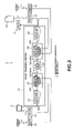
- FIG. 2 illustrates the flow of image data in the image-processing apparatus shown in FIG. 1 .
- the devices may differ in terms of the darkest points. (That is, the black part of the image that one device outputs may differ from that of the image that another device outputs.) Particularly in this case, the images output by the devices appear greatly different. Assume that the darkest point of an input device differs from that of an output device. Then, either graying or black-emphasizing occurs in the image output by the output device. Consequently, the input image and the output image may look quite different in terms of color.
- the present invention has been made in consideration of the foregoing.
- the object of the invention is to provide an image-processing apparatus and an image-processing method which process image data so that the images represented by the data and reproduced by different devices may look almost identical in terms of color.
- an image-processing apparatus for processing the image data input from an image-handling device and then outputting the image data to another image-handling device.
- the image-processing apparatus comprises black-adaptation correction means for correcting the image data in consideration of the fact that adaptation to black varies from person to person, if the darkest points of the image-handling devices differ from each other, so that the colors of the images produced by the image-handling devices look almost the same.
- the black-adaptation correction means corrects the image data if the darkest points of the image-handling devices differ from each other, in consideration of the fact that adaptation to black varies from person to person. Hence, the colors of the images produced by the image-handling devices look almost the same even if the darkest points of the image-handling devices differ from each other.
- a method of processing image data input from an image-handing device before the image data is output to another image-handling device comprises the step of correcting the image data in consideration of the fact that adaptation to black varies from person to person, if the darkest points of the image-handling devices differ from each other, so that the colors of the images produced by the image-handling devices look almost the same.
- the image data is corrected if the darkest points of the image-handling devices differ from each other, in consideration of the fact that adaptation to black varies from person to person. Hence, the colors of the images produced by the image-handling devices look almost the same even if the darkest points of the image-handling devices differ from each other.
- image data is corrected if the darkest points of image-handling devices differ from each other, in consideration of the fact that adaptation to black varies from person to person.
- the colors of the images produced by the image-handling devices look almost the same even if the darkest points of the image-handling devices differ from each other.
- the present invention enables the devices of different types to reproduce color images that appears identical in color, although the adaptation to black varies from person to person
- FIG. 1 is a schematic representation of a conventional image-processing apparatus
- FIG. 2 is a diagram illustrating the flow of image data in the conventional image-processing apparatus
- FIG. 3 is a diagram showing an image-processing apparatus according to the present invention.
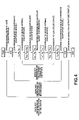
- FIG. 4 is a diagram illustrating the image-processing sequence performed in the image-processing apparatus shown in FIG. 3 ;
- FIG. 5 is a diagram explaining the process of converting an image of the color gamut for the input-side device to an image of the color gamut for the output-side device, through a device optimal color space;
- FIG. 6 is a graph representing the relationship between the color gamut of the medium and the black adaptation rate K adp ;
- FIG. 7 is a graph shows the relationship between the Y value (Y OP 1/3 ) present in the device optimal color space and the Y value (Y S 1/3 ) present in the color space which is to be converted to the device optimal color space;
- FIG. 9 is a diagram showing another image-processing apparatus according to the present invention.
- FIG. 10 is a diagram depicting a menu screen designed to set parameters concerning the environment in which an image is observed;
- FIG. 11 is a diagram showing another image-processing apparatus according to the present invention.
- FIG. 12 is a diagram illustrating an image-processing apparatus according to the invention, which is provided in the form of a computer system.
- any image displayed by an image display device shall be called soft copy image
- any image printed on a recording medium such as a paper sheet shall be called hard copy image.
- the media for soft copy images are image display devices
- the media for hard copy images are recording media such as paper sheets.
- FIG. 3 shows an image-processing apparatus 1 according to this invention.
- the image-processing apparatus 1 receives the image data representing the image displayed by an image display 2 such as a CRT display or a liquid crystal display.
- the apparatus 1 processes the image data and outputs the same to a printer 3 .
- the input-side device is the image display 2
- the output-side device is the printer 3
- the input- and output-side devices are not limited to an image display and a printer, respectively.
- the input-side device may be an image scanner, a camera or the like
- the output-side device may be an image display or the like.
- the input- and output-side devices are connected directly to the image-processing apparatus 1 . Instead, these devices may be connected to the apparatus 1 by a network.
- the image-processing apparatus 1 comprises a image-processing section 11 , a first input-side sensor 12 , a second input-side sensor 13 , a first output-side sensor 15 , and a second output-side sensor 16 .
- the image-processing section 11 processes the image data received from the image display 2 .
- the first input-side sensor 12 receives light L 1 emitted from the image display 2 , thereby detecting the reflectance and the like of the screen of the image display 2 .
- the second input-side sensor 13 detects the ambient light L 2 existing at the time of observing the image displayed by the image display 2 .
- the first output-side sensor 15 receives the light L 3 from a print sheet 14 on which the printer 3 will print the image, thereby detecting the total luminance and the like of the print sheet 14 .
- the second output-side sensor 16 detects the ambient light L 4 existing at the time of observing the image printed on the print sheet 14 by the printer 3 .
- the image-processing section 11 comprises an input-side converter 21 , an input-side observation environment changing circuit 22 , an image-editing circuit 23 , an output-side observation environment changing circuit 24 , and an output-side converter 25 .
- the input-side converter 21 receives the RGB value of the image displayed by the image display 2 . Using an input-side device profile, the converter 21 converts the RGB value to an XYZ value, or a tristimulus value based on the human visual sense.
- the input-side device profile is a file that contains conversion formula or a conversion table for converting the RGB value received from the image display 2 , to a XYZ value based on the human visual sense. The profile has been prepared on the basis of the characteristics of the image display 2 .
- the XYZ value is supplied from the input-side converter 21 to the input-side observation environment changing circuit 22 .
- the input-side observation environment changing circuit 22 a conversion process based on a chromatic adaptation model (S-LMS) later described, on the XYZ value received from the input-side converter 21 . Further, the circuit 22 performs a conversion process on the XYZ value so that the value may be used in the device optimal color space as will be described later Thus, the circuit 22 converts the XYZ value to an XYZ value (X OP Y OP Z OP ) for use in a device optimal color space. (Hereinafter, the XYZ value obtained by the conversion will be called X OP Y OP Z OP value.
- the X OP Y OP Z OP value is supplied from the input-side observation environment changing circuit 22 to the image-editing circuit 23 .
- the input-side observation environment changing circuit 22 receives, from the first input-side sensor 12 , the detection signal representing the reflectance and the like of the screen of the image display 2 .
- the circuit 22 also receives, from the second input-side sensor 13 , the detection signal representing the ambient light L 2 that exists at the time of observing the image displayed by the image display 2 . From in these detection signals the circuit 22 obtains the parameters concerning the environment in which the image displayed by the image display 2 is observed. Using the parameters, the circuit 22 performs a conversion process based on the chromatic adaptation model and a conversion process for making it possible to use the XYZ value in the device optimal color space.
- the image-editing circuit 23 effects an image-editing process, such as color gamut compression, on the X OP Y OP Z OP value received from the input-side observation environment changing circuit 22 .
- the X OP Y OP Z OP value, thus processed, is supplied from the image-editing circuit 23 to the output-side observation environment changing circuit 24 .
- the output-side observation environment changing circuit 24 processes the X OP Y OP Z OP value, thereby converting the same from one for use in the device optimum color space to one for use in an LMS color space. Further, the circuit 24 performs an inverse conversion process based on the chromatic adaptation model, which will be described later. Thus, the circuit 24 converts the X OP Y OP Z OP value received from the image-editing circuit 23 , to an XYZ value, which is a tristimulus value, based on the human visual sense.
- the output-side observation environment changing circuit 24 receives the detection signal output from the first output-side sensor 15 and the detection signal output from the second output-side sensor 16 .
- the detection signal output by the sensor 15 represents the total luminance and the like of the print sheet 14 on which the printer 3 will print the image.
- the detection signal output by the sensor 16 represents the ambient light L 4 existing at the time of observing the image printed on the print sheet 14 by the printer 3 . From these detection signals the circuit 24 obtains parameters concerning the environment in which the image printed on the print sheet 14 by the printer 3 is observed. Using these parameters, the circuit 24 converts the X OP Y OP Z OP value, from one for use in the device optimum color space to one for use in an LMS color space, and effects conversion process based on the chromatic adaptation model.
- the output-side converter 25 receives the XYZ value from the output-side observation environment changing circuit 24 .
- the output-side converter 25 converts the XYZ value to a CMY value (or a CMYK value) that the printer 3 will used to print the image, by using the an output-side device profile.
- the output-side device profile is a file that contains conversion formula or a conversion table for converting the XYZ value based on the human visual sense to a CMY value, which the printer 3 will use to print the image.
- the output-side profile has been prepared on the basis of the characteristics of the printer 3 .
- the CMY value is supplied from the output-side converter 25 to the printer 3 .
- the printer 3 prints the image on a print sheet 14 .
- the input-side converter 21 performs a conversion process based on the input-side device profile, on the RGB value of the image displayed by the image display 2 .
- the RGB value is thereby converted to an XYZ value.
- the input-side observation environment changing circuit 22 subjects the XYZ value to a conversion process based on the chromatic adaptation model.
- the XYZ value is thereby converted to an LMS value for used in an LMS color space that does not depend on the observation environment.
- the LMS value will be called L S M S S S value.
- the input-side observation environment changing circuit 22 converts the L S M S S S value to an X OP Y OP Z OP value for use in the device optical color space.
- the image-editing circuit 23 subjects the X OP Y OP Z OP value to an image-editing process, such as color gamut compression.
- the X OP Y OP Z OP value is converted to an L*a*b* value for use in a sense-equivalent color space.
- the L*a*b* value will be referred to as L S *a S *b S * value.
- the circuit 23 then performs the image-editing process, such as color gamut compression, on the L S *a S *b S * value. Further, the circuit 23 converts the L S *a S *b S * value, thus processed, to the X OP Y OP Z OP value for use in the device optimal color space.
- the output-side observation environment changing circuit 24 converts the X OP Y OP Z OP value to a L S M S S S value for use in the LMS color space that does not depend on the observation environment
- the circuit 24 subjects the L S M S S S value to a conversion process based on the chromatic adaptation model, thus converting the L S M S S S value to an XYZ value.
- the output-side converter 25 converts the XYZ value to a CMY value.
- the CMY value is output to the printer 3 .
- the data converted on the basis of the input-side device profile remains not depending on the color space of the device until it is subjected to the conversion process based on the chromatic adaptation model.
- the data converted on the basis of the data converted on the basis of the input-side device profile remains not depending on the color space of the device until it is subjected to the conversion process based on the chromatic adaptation model does not depend on the observation environment until it is subjected to the inverse conversion process based on chromatic adaptation model.
- the data converted for use in the device optical color space remains not depending on the dynamic range of the device until it is converted to an L S M S S S value for use in the LMS color space that does not depend on the observation environment.
- the conversion process which the input-side observation environment changing circuit 22 performs in the image-processing apparatus 1 on the basis of the chromatic adaptation model, will be explained in detail. It should be noted that the output-side observation environment changing circuit 24 effects an inverse conversion process based on the chromatic adaptation model, as will be described below.
- the conversion process based on the chromatic adaptation model is carried out to compensate for the change in color of the image viewed in the observation environment that includes ambient light.
- the conversion process based on the chromatic adaptation model is a process of compensating for correcting the color of the image viewed in the observation environment that includes ambient light.
- the chromatic adaptation model used here is fundamentally a Von Kries adaptation model.
- the model is processed in three major steps.
- the first step is correction of contrast
- the second step is conversion of a tristimulus value to a cone signal
- the third step is correction of chromatic adaptation.
- the third steps consists of two sub-steps.
- the first sub-step is consideration of incomplete adaptation
- the second sub-step is consideration of mixed adaptation.
- the parameters concerning the environment in which the image is observed are obtained from the reflectance and the like of the screen of the image display 2 , which have been detected by the first input-side sensor 12 , and the ambient light L 2 which exists at the time of observing the image displayed by the image display 2 and which has been detected by the second input-side sensor 13 .
- the parameters concerning the environment in which the image is observed are obtained from the total luminance and the like of the print sheet 14 , which have been detected by the first output-side sensor 15 , and the ambient light L 4 which exists at the time of observing the image printed on the print sheet 14 by the printer 3 and which has been detected by the second output-side sensor 16 .
- Correction of contrast is first performed in the conversion process based on the chromatic adaptation model.
- the ambient light has high luminance, the image that the image display 2 displays will have low contrast. This is because the screen of the image display 2 reflects the ambient light, inevitably causing black-emphasis.
- Most image displays such as CRT displays and liquid crystal displays, have an antireflection film on the screen. The antireflection film cannot completely prevent the reflection of ambient light at the screen. As long as the ambient light exists, the black reproduced on the screen cannot be darker than the black provided by the light reflected from the screen. As the CIELAB formula teaches, the human visual sense is keen to dark colors, and the contrast of the image decreases if black is emphasized. Therefore, the light reflected from the screen of the image display 2 is taken into consideration to accomplish the correction of contrast.
- an offset value corresponding to the light reflected from the screen is added to the XYZ value that has been obtained by converting the RGB value of the image displayed by the image display 2 .
- An X′ Y′ Z′ value is thereby obtained as can be understood from the following equation (1-1).
- the XYZ value is normalized with Y′ MW expressed by the following equation(1-2), so that Y′ may acquire the maximum value of 1.
- R bk is the reflectance of the screen of the image display (usually, 3 to 5% in the case of CRT displays)
- X PRD Y PRD Z PRD is the absolute luminance that the ambient light has when reflected by a perfect reflecting diffuser
- Y MW is the absolute luminance of the white point of the medium (i.e., the image display 2 ).
- the input-side device is the image display 2 , it is desirable to perform the correction of contrast as has been described above. If the input-side device is an image scanner or the like and if the image subjected to the correction of contrast is a hard copy image, it will be unnecessary to carry out the correction of contrast.
- the X ′ Y ′ Z ′ value is normalized with Y′ MW expressed by the following equation (1-4), thereby obtaining X ′ Y ′ Z ′.
- Y paper is the absolute luminance at the white point of the medium. In the case where an image scanner reads the image printed on a paper sheet, Y paper is the absolute luminance of the paper sheet on which the image has been printed.
- the tristimulus value i.e., XYZ value
- LMS value cone signal
- the most appropriate matrix formula is selected from among the above-mentioned formulae in accordance with the characteristics and the like of the image, and X′ Y′ Z′ are converted to LMS in accordance with the matrix formula selected.
- the receptor cells called ones in the human retina have their sensitivity changed to perceive a light source as being white, in the same manner as white balance is attained in a video camera That is, the signals generated by the cones are normalized with the value of the white point. To cope with the changes in the sensitivity of the cones, the chromatic adaptation is corrected on the basis of the Von Kries adaptation model.
- the human visual sense is not always fully adapted to the white point of a light source. Hence, the chromaticity of the light is not used as the while point (hereinafter referred to as adaptation white point to which the human visual sense is adapted. Rather, in the present model, the adaptation white point is determined from incomplete adaptation and mixed adaptation.
- an adaptation white point (hereinafter called incomplete adaptation white point is determined in the image-processing apparatus 1 .
- the incomplete adaptation white point can be determined by, for example, the Hunt, R-LAB system, the Naya system and the CIECAM97s system. These systems will be described below.
- the system which seems the most appropriate in accordance with the characteristics and the like of the image, is selected from these systems, and the incomplete adaptation white point is determined by the system selected.
- L ′ MW M ′ MW S ′ MW is the LMS value of the incomplete adaptation white point
- L MW M MW S MW is the LMS value obtained by normalizing the tristimulus value X MW Y MW Z MW of the absolute-luminance of the white point on the screen.
- the symbol Y′ MW is the absolute luminance [cd/m 2 ] represented by the equation (1-2) or (1-4) described above.
- P L ( 1 + Y MW ′1 / 3 + l E ) / ( 1 + Y MW ′1 / 3 + 1 / l E )
- P M ( 1 + Y MW ′1 / 3 + m E ) / ( 1 + Y MW ′1 / 3 + 1 / m E )
- P S ( 1 + Y MW ′1 / 3 + s E ) / ( 1 + Y MW ′1 / 3 + 1 / s E ) ⁇ ( 1 ⁇ - ⁇ 13 )
- l E 3 ⁇ L _ MW / ( L
- a nonlinear exponential parameter needs to be provided for S ′ MW in the actual CIECAM97s system, but such an exponential parameter is deleted from the equation (1-14) for the sake of simplicity. The exponential parameter may of course be taken into consideration.
- the input-side device may be an image scanner or the like, and the image processed may be a hard copy image. In this case, it is unnecessary to apply incomplete adaptation, and the value of L ′ MW M ′ MW S ′ MW (LMS value), obtained by normalizing the tristimulus value L MW M MW S MW of the white point of the medium, is applied without being modified, as can be seen from the following equation (1-16).
- LMS value LMS value
- the image displayed by the image display 2 i.e., a soft copy image
- a soft copy image is scarcely observed in a dark room.
- the image is observed under fluorescent lamps that have a correlation color temperature (CCT) of about 4150K.
- CCT correlation color temperature
- the correlation color temperature of the white point of CRT displays widely as image displays is approximately 9300K.
- the white point of the medium i.e., image display 2
- the white point of the medium i.e., image display 2
- the white point of the medium i.e., image display 2
- the white point of the medium usually has a color temperature that differs from the color temperature of the ambient light.
- the recording medium In the case of the image printed on a recording medium (i.e., a hard copy image), the recording medium is usually a white paper sheet. The image may be printed on a yellowish paper sheet, such as newspaper sheets. If the recording medium is not perfectly white, the white point of the recording medium differs from the white of the ambient light. That is, in the case of a hard copy image, too, the white point of the recording medium (i.e., a paper sheet or the like) may differ from the color temperature of the ambient light in some cases.
- the white point of the medium may differ from the color temperature of the ambient light. If so, the human visual sense is regarded as partly adapted to both the white point and the color temperature. Let us assume, therefore, that the white point to which our visual sense is adapted lies some where between the white point of the medium and the color temperature of the ambient light. Then, the LMS value (i.e., L ′′ MW M ′′ MW S ′′ MW ) of the white point to which our visual sense is actually adapted is defined by the following equations (1-17) and (1-18), where R adp is the adaptation ratio at which the human visual sense is adapted to the white of the medium.
- L PRD M PRD S PRD is the LSM value that has been obtained by normalizing the tristimulus value X PRD Y PRD Z PRD of the absolute luminance of the ambient light reflected from a perfect reflecting diffuser.
- Symbol Y′ MW is the absolute luminance of the white point of the medium. (The absolute luminance is one evaluated in consideration of the light reflected from the screen, if the medium is the image display 2 ). If the medium is the image display 2 , Y′ MW is the absolute luminance of the white point of the screen of the display 2 . If the medium is a white paper sheet, Y′ MW is the absolute luminance of the paper sheet.
- weighting coefficients (Y′ NW /Y adp ) 1/3 and (Y′ PRD /Y adp ) 1/3 . These coefficients are applied when the absolute luminance of the ambient light reflected from the perfect reflecting diffuser differs from the absolute luminance of the white point of the medium.
- the adaptation ratio R adp be about 0.4 to 0.7 in normal environment. More precisely, is set to 0.6.
- the adaptation ratio R adp of 1.0 means that the human visual sense is perfectly (100%) adapted to the medium, not influenced by the ambient light at all. In other words, the ratio R adp is 1.0 when the human visual sense is adapted 100% to the image display 2 , not influenced by the ambient light, if the medium used is the image display 2 , or when the visual sense is adapted 100% to the recording medium, not influenced by the ambient light, if the recording medium used is, for example, a paper sheet.
- the ratio R adp of 1.0 is achieved when CIELAB is adjusted to the human visual sense.
- the value of 0.0 is attained when the human visual sense is adapted 100% to the ambient light. This is equivalent to the CIE/XYZ adjusted to the human visual sense.
- the adaptation white point ( L ′′ MW M ′′ MW S ′′ MW ) that has been obtained in consideration of the incomplete adaptation and mixed adaptation is substituted in the Von Kries adaptation rule, as indicated in the following equation (1-19).
- the color adaptation is thereby corrected, providing an LMS value (L S M S S S ) that does not depend on the observation environment.
- LMS in the right side is a value obtained in the second step of converting a tristimulus value to a cone signal, which has been described above.
- the input-side observation environment changing circuit 22 of the image-processing apparatus 1 performs the conversion process based on the chromatic adaptation model
- the circuit 22 converts the XYZ value received from the input-side converter 21 , to an LMS value (L S M S S S ) for the LMS color space that does not depend on the observation environment.
- the output-side observation environment changing circuit 24 of the image-processing apparatus 1 effects the inverse conversion process based on the chromatic adaptation model.
- the conversion process to the device optimal color space is carried out in consideration of black-adaptation correction.
- the black-adaptation correction is effected so that a color looks almost the same on whichever medium, even if the darkest points of the media have different tristimulus values.
- an image is merely converted from the color gamut of a medium to the color gamut of another medium. Then, the color of the image appears different to the human eyes if the darkest points of the media have different tristimulus values. This is inevitably because the adaptation to black varies from person to person. This is why the black-adaptation correction is performed, whereby the color looks almost the same on whichever medium even if the darkest points of these media have different tristimulus values.
- the color space is changed to the device optimal color space, thus effecting the black-adaptation correction, in order to converts the image from the color gamut of the input-side device to the color gamut of the output-side device.
- Ambient light if any, influences the human visual sense.
- the color gamut S 1 the image has when ambient light exists differs from the color gamut S 2 the image has when no ambient light exists.
- the black-adaptation correction is carried out by using the XYZ value of the darkest point on the medium (i.e., the XYZ value of the black point) and the XYZ value of the most luminous point on the medium (i.e., the XYZ value of the white point).
- the conversion process to the device optimal color space is performed in consideration of black-adaptation correction, in the following manner.
- the LMS value (L S M S S S ) defined by the equation (1-19) is converted to a value (X S Y S Z S ) for use in the XYZ color space, as follows:
- the XYZ value (X S,K Y S,K Z S,K ) of the black point that man may perceive as being darkest is defined by the following equation (2-2). This if the black-adaptation correction.
- X S,MK Y S,MK Z S,MK is the tristimulus value for the black point of the medium and X PK Y PK Z PK is the tristimulus value for the light reflected from the perfectly black part These values must be 0 in ideal condition.
- K adp is the rate of adaptation to the human eyes and ranges from 0 to 1.
- FIG. 6 shows the relationship between the color gamut of the medium and the rate K adp of adaptation to black. The adaptation rate K adp having this relationship with the color gamut of the medium is applied, accomplishing the black-adaptation correction.
- X PK Y PK Z PK is the tristimulus value for the light reflected from the perfectly black part and must be 0 in the ideal condition.
- the XYZ value (X S Y S Z S ) obtained by the process of the equation (2-1) is converted to an XYZ value (X OP Y OP Z OP ) in the device optimal color space that corresponds to the dynamic range of the device.
- FIG. 7 is a graph showing an example of the function expressed by the above equation (2-5).
- the Y value (Y OP 1/3 ) present in the device optimal, color space is plotted on the ordinate
- the Y value (Y S 1/3 ) present in the color space to be converted to the device optimal color space is plotted on the abscissa.
- the input-side observation environment changing circuit 22 performs the conversion process to the device optimal color space in consideration of the black-adaptation correction.
- the LMS value (L S M S S S ) obtained in the conversion process based on the color adaptation model is converted to an XYZ value (X OP Y OP Z OP ) for use in the device optimal color space that corresponds to the dynamic range of the device.
- the XYZ value (X OP Y OP Z OP ) obtained in the conversion process to the device optimal color space is supplied to the image-editing circuit 23 .
- the image-editing circuit 23 performs an image-editing process, such as color gamut compression.
- the X OP Y OP Z OP value is converted to an L S *a S *b S * value. This conversion is expressed by the following equations (2-7):
- the image-editing circuit 23 performs an image-editing process, such as color gamut compression, on the L S *a S *b S * value thus obtained. Thereafter, the image-editing circuit 23 converts the L S *a S *b S * value to the X OP Y OP Z OP value.
- the X OP Y OP Z OP value is supplied to the output-side observation environment changing circuit 24 .
- the image-editing process is not absolutely necessary in the present invention; it may not be carried out.
- the X OP Y OP Z OP value is supplied to from the output-side observation environment changing circuit 24 to the output-side device through the output-side converter 25 .
- the output-side converter 25 needs to have a color space optimal to it. This is because the X OP Y OP Z OP value must pass through an optimal color space before supplied to the output-side device.
- the optimal color space of the output-side device is identical to the optimal color space of the input-side device. Therefore, the following equations (2-8) hold true. Suffix IN to some symbols in the equations (2-8) et. seq. indicates that the values pertain to the input-side device, while suffix OUT to some other symbols means that the values pertain to the output-side device.
- the device optimal color spaces can be given by the equations (2-5) shown above.
- the equations (2-5) can be replaced by the following equations (2-9):
- the output-side converter 25 converts the XYZ value supplied from the circuit 24 , to a CMY value on the basis of the output-side device profile.
- the output-side converter 25 outputs the CMY value to the printer 3 .
- the black-adaptation correction is effected the adaptation to black varies from person to person.
- the colors of the image appears almost the same in both the input-side device and the output-side device, even if the darkest points of the input- and output-side devices differ from each other.
- the image displayed by the image display 2 and the image printed by the printer 3 which has received the data representing the image produced by the display 2 looks almost the same, though the darkest points of the image display 2 and the printer 3 differ from each other.
- the first and second input-side sensors 12 and 13 and the first and second output-side sensors 15 and 16 are used to obtain the parameters concerning the observation environment, which are applied in the image-converting process. These parameters may be input directly to the image-processing apparatus 1 .
- FIG. 9 shows an image-processing apparatus 51 that directly receives the parameters concerning the environment in which the image is observed.
- the components of the apparatus 51 shown in FIG. 9 which are similar to those of the image-processing apparatus 1 shown in FIG. 3 are designated at the same reference numerals.
- the image-processing apparatus 51 comprises two parameter-setting circuits 52 and 53 , in place of the sensors 12 , 13 , 15 and 16 used in the image-processing apparatus 1 of FIG. 3 .
- the parameter-setting circuit 52 is connected to the input-side observation environment changing circuit 22 , and the parameter-setting circuit 53 to the output-side observation environment changing circuit 24 .
- the parameters that the circuit 22 needs to convert image data are input to the circuit 22 via the parameter-setting circuit 52 connected to the input-side observation environment changing circuit 22 . Using the parameters thus input, the input-side observation environment changing circuit 22 performs the conversion of image data. Further, the parameters that the circuit 24 needs to convert image data are input to the circuit 24 via the parameter-setting circuit 53 connected to the output-side observation environment changing circuit 24 . Using these parameters, the output-side observation environment changing circuit 24 performs the conversion of image data.
- a menu screen be used, which is, for example, such a graphical user interface as is illustrated in FIG. 10 .
- the screen menu shown in FIG. 10 is one used to cause the parameter-setting circuit 52 to set parameters.
- the screen menu is designed, enabling the user of the apparatus 51 to select an indoor-light chromaticity (light source), an indoor-light luminance (surround luminance) and a luminance for the image display 2 (monitor luminance), each from a plurality of choices.
- “F6”, “Dark” and “Mid” are selected for the indoor-light chromaticity, indoor-light luminance and luminance for the image display 2 , respectively.
- the parameter-setting circuit 52 stores the parameters about the observation environment which correspond to these various choices.
- the parameter-setting circuit 52 reads the parameters that correspond to the choices selected and supplies these parameters to the input-side observation environment changing circuit 22 .
- the parameters corresponding to the “F 6 ”, “Dark” and “Mid” are selected for the indoor-light chromaticity 6 , the indoor-light luminance “Dark”, and the image display luminance “Mid” are supplied to the input-side observation environment changing circuit 22 .
- the circuit 22 converts the image data in accordance with these parameters.
- the input-side device and the output-side device are the image display 2 and the printer 3 , respectively.
- the input- and output-side devices are not limited to these
- the input-side device and the output-side device may be an image scanner 62 and an image display 63 , as in the image-processing apparatus 61 illustrated in FIG. 11 .
- the components of this apparatus 61 which are similar to those of the apparatus 1 shown in FIG. 3 , are designated at the same reference numerals as in FIG. 3 .
- the first input-side sensor 12 detects the light L 5 reflected from the paper sheet 64 on which the image has been printed to be read by the image scanner 62 . From the light L 5 the sensor 12 determines the total luminance of the printed paper sheet 64 .
- the second input-side sensor 13 detects the ambient light L 6 existing when the image printed on the paper sheet 64 is observed.
- the first output-side sensor 15 detects the light L 7 from the image display 63 and determines therefrom the reflectance and the like of the screen of the image display 63 .
- the second output-side sensor 16 detects the ambient light L 8 existing when the image displayed by the image display 63 is observed.
- the present invention is not to the embodiments depicted in FIGS. 3 and 11 . Rather, the invention can be applied to such a computer system 71 as is illustrated in FIG. 12 .
- the computer system 71 of FIG. 12 comprises a central processing unit (CPU) 72 , a system controller 73 , a cache memory 74 , a random-access memory 75 , an external storage control section 76 , an input control section 77 , an image data input/output control section, 78 , a video controller 79 , a sensor control section 80 , and a communication control section 81 . These components are connected to a bus 82 .
- the external storage control section 76 serves as an interface with an external storage device.
- the section 76 is connected to, for example, a hard disk drive 83 or a CD-ROM drive 84 .
- the input control section 77 functions as an interface with an input device.
- the section 77 is connected to, for example, a keyboard 85 , a mouse-type pointing device 86 .
- the image data input/output control section 78 is provided as an interface with a device which handles image data.
- the section 78 is connected to, for example, an image scanner 87 or a printer 88 .
- the video controller 79 serves as an interface with an image display. It is connected to, for example, a CRT display 89 .
- the sensor control section 80 operates as an interface with external sensors.
- the section 80 is connected, for example, the first and second input-side sensors 12 and 13 and the first and second output-side sensors 15 and 16 , all identical to their counterparts of the image-processing apparatus 1 .
- the communication control section 81 functions as an interface with a communication apparatus.
- the section 81 is connected to, for example, a modem 91 or a hub 92 .
- the computer system 71 can therefore be connected to the telephone line by the modem 91 that is connected to the communication control section 81 .
- the computer system 71 can be connected to a predetermined network by the hub 92 that is connected to the communication control section 81 .
- the CPU 72 processes image data in the same way as the image-processing section 11 does in the image-processing apparatus 1 , under the control of the system controller 73 with the assistance of the cache memory 74 and random-access memory 75 .
- the computer system 71 receives the image data from the input-side device (e.g., image scanner 87 or the like) by the use of the image data input/output control section 78 or the video controller 79 .
- the CPU 72 processes the image data in the same way as the image-processing section 11 does in the image-processing apparatus 1 .
- the image data thus processed is output to the output-side device (e.g., printer 88 , CRT display 89 , or the like) through the image data input/output control section 78 or the video controller 79 .
- the black-adaptation correction is effected in the computer system as in the image-processing apparatus 1 when the CPU 72 processes the image data, because the adaptation to black varies from person to person As a result, the colors of the images produced by the input- and output-side devices look almost the same, even if the darkest points of the input- and output-side devices differ from each other.
Abstract
An image-processing apparatus for processing the image data input from an image-handling device and then outputting the image data to another image-handling device. The apparatus comprises a black-adaptation correction device. The black-adaptation correction device corrects the image data in consideration of the fact that adaptation to black varies from person to person, if the darkest points of the image-handling devices differ from each other. Since the image is so corrected, the colors of the images produced by the image-handling devices look almost the same in spite of the fact that the darkest points of the image-handling devices differ from each other.
Description
This is a continuation of application Ser. No. 09/455,576 filed Dec. 6, 1999 now U.S. Pat. No. 6,912,306, the entirety of which is incorporated herein by reference.
The present invention relates to an apparatus for processing the image data input from an image-handing device and then outputting the image data to another image-handling device. The invention also relates to a method of processing image data input from an image-handing device before the image data is output to another image-handling device.
As various systems which handle color images come into use in increasing numbers, it is demanded that color images be reproduced in the same hues by the devices of different types that are used in these systems. To meet this demand, image-processing apparatuses have been proposed, each designed to evaluate the devices for their characteristics and adjust the color values of the image output from the devices to the same value. FIG. 1 shows such an image-processing apparatus. FIG. 2 illustrates the flow of image data in the image-processing apparatus shown in FIG. 1 .
Even if the color values of the images output from the devices are adjusted to the same value, however, the colors of the images do not always appear identical to human eyes. This is because the observation environment including ambient light influences the human visual sense. That is to say, the same color looks different in different observation environments.
The devices may differ in terms of the darkest points. (That is, the black part of the image that one device outputs may differ from that of the image that another device outputs.) Particularly in this case, the images output by the devices appear greatly different. Assume that the darkest point of an input device differs from that of an output device. Then, either graying or black-emphasizing occurs in the image output by the output device. Consequently, the input image and the output image may look quite different in terms of color.
The present invention has been made in consideration of the foregoing. The object of the invention is to provide an image-processing apparatus and an image-processing method which process image data so that the images represented by the data and reproduced by different devices may look almost identical in terms of color.
According to the first aspect of the present invention, there is provided an image-processing apparatus for processing the image data input from an image-handling device and then outputting the image data to another image-handling device. The image-processing apparatus comprises black-adaptation correction means for correcting the image data in consideration of the fact that adaptation to black varies from person to person, if the darkest points of the image-handling devices differ from each other, so that the colors of the images produced by the image-handling devices look almost the same.
In the image-processing apparatus, the black-adaptation correction means corrects the image data if the darkest points of the image-handling devices differ from each other, in consideration of the fact that adaptation to black varies from person to person. Hence, the colors of the images produced by the image-handling devices look almost the same even if the darkest points of the image-handling devices differ from each other.
According to the second aspect of the invention, there is provided a method of processing image data input from an image-handing device before the image data is output to another image-handling device. The method comprises the step of correcting the image data in consideration of the fact that adaptation to black varies from person to person, if the darkest points of the image-handling devices differ from each other, so that the colors of the images produced by the image-handling devices look almost the same.
In the image-processing method, the image data is corrected if the darkest points of the image-handling devices differ from each other, in consideration of the fact that adaptation to black varies from person to person. Hence, the colors of the images produced by the image-handling devices look almost the same even if the darkest points of the image-handling devices differ from each other.
As mentioned above, in the present invention, image data is corrected if the darkest points of image-handling devices differ from each other, in consideration of the fact that adaptation to black varies from person to person. Hence, the colors of the images produced by the image-handling devices look almost the same even if the darkest points of the image-handling devices differ from each other. In short, the present invention enables the devices of different types to reproduce color images that appears identical in color, although the adaptation to black varies from person to person
Embodiments of the present invention will be described in detail, with reference to the accompanying drawings.
In the following description, any image displayed by an image display device shall be called soft copy image, and any image printed on a recording medium such as a paper sheet shall be called hard copy image. In other words, the media for soft copy images are image display devices, whereas the media for hard copy images are recording media such as paper sheets.
1. Structure of the Image-Processing Apparatus
In this case, the input-side device is the image display 2, and the output-side device is the printer 3. According to the present invention, however, the input- and output-side devices are not limited to an image display and a printer, respectively. For example, the input-side device may be an image scanner, a camera or the like, and the output-side device may be an image display or the like. As shown in FIG. 3 , the input- and output-side devices are connected directly to the image-processing apparatus 1. Instead, these devices may be connected to the apparatus 1 by a network.
As shown in FIG. 3 , the image-processing apparatus 1 comprises a image-processing section 11, a first input-side sensor 12, a second input-side sensor 13, a first output-side sensor 15, and a second output-side sensor 16. The image-processing section 11 processes the image data received from the image display 2. The first input-side sensor 12 receives light L1 emitted from the image display 2, thereby detecting the reflectance and the like of the screen of the image display 2. The second input-side sensor 13 detects the ambient light L2 existing at the time of observing the image displayed by the image display 2. The first output-side sensor 15 receives the light L3 from a print sheet 14 on which the printer 3 will print the image, thereby detecting the total luminance and the like of the print sheet 14. The second output-side sensor 16 detects the ambient light L4 existing at the time of observing the image printed on the print sheet 14 by the printer 3. The image-processing section 11 comprises an input-side converter 21, an input-side observation environment changing circuit 22, an image-editing circuit 23, an output-side observation environment changing circuit 24, and an output-side converter 25.
The input-side converter 21 receives the RGB value of the image displayed by the image display 2. Using an input-side device profile, the converter 21 converts the RGB value to an XYZ value, or a tristimulus value based on the human visual sense. The input-side device profile is a file that contains conversion formula or a conversion table for converting the RGB value received from the image display 2, to a XYZ value based on the human visual sense. The profile has been prepared on the basis of the characteristics of the image display 2. The XYZ value is supplied from the input-side converter 21 to the input-side observation environment changing circuit 22.
The input-side observation environment changing circuit 22 a conversion process based on a chromatic adaptation model (S-LMS) later described, on the XYZ value received from the input-side converter 21. Further, the circuit 22 performs a conversion process on the XYZ value so that the value may be used in the device optimal color space as will be described later Thus, the circuit 22 converts the XYZ value to an XYZ value (XOPYOPZOP) for use in a device optimal color space. (Hereinafter, the XYZ value obtained by the conversion will be called XOPYOPZOP value. The XOPYOPZOP value is supplied from the input-side observation environment changing circuit 22 to the image-editing circuit 23.
To convert the XYZ value received from the input-side converter 21, the input-side observation environment changing circuit 22 receives, from the first input-side sensor 12, the detection signal representing the reflectance and the like of the screen of the image display 2. The circuit 22 also receives, from the second input-side sensor 13, the detection signal representing the ambient light L2 that exists at the time of observing the image displayed by the image display 2. From in these detection signals the circuit 22 obtains the parameters concerning the environment in which the image displayed by the image display 2 is observed. Using the parameters, the circuit 22 performs a conversion process based on the chromatic adaptation model and a conversion process for making it possible to use the XYZ value in the device optimal color space.
The image-editing circuit 23 effects an image-editing process, such as color gamut compression, on the XOPYOPZOP value received from the input-side observation environment changing circuit 22. The XOPYOPZOP value, thus processed, is supplied from the image-editing circuit 23 to the output-side observation environment changing circuit 24.
The output-side observation environment changing circuit 24 processes the XOPYOPZOP value, thereby converting the same from one for use in the device optimum color space to one for use in an LMS color space. Further, the circuit 24 performs an inverse conversion process based on the chromatic adaptation model, which will be described later. Thus, the circuit 24 converts the XOPYOPZOP value received from the image-editing circuit 23, to an XYZ value, which is a tristimulus value, based on the human visual sense.
In order to convert the XOPYOPZOP value received from the image-editing circuit 23, the output-side observation environment changing circuit 24 receives the detection signal output from the first output-side sensor 15 and the detection signal output from the second output-side sensor 16. The detection signal output by the sensor 15 represents the total luminance and the like of the print sheet 14 on which the printer 3 will print the image. The detection signal output by the sensor 16 represents the ambient light L4 existing at the time of observing the image printed on the print sheet 14 by the printer 3. From these detection signals the circuit 24 obtains parameters concerning the environment in which the image printed on the print sheet 14 by the printer 3 is observed. Using these parameters, the circuit 24 converts the XOPYOPZOP value, from one for use in the device optimum color space to one for use in an LMS color space, and effects conversion process based on the chromatic adaptation model.
The output-side converter 25 receives the XYZ value from the output-side observation environment changing circuit 24. The output-side converter 25 converts the XYZ value to a CMY value (or a CMYK value) that the printer 3 will used to print the image, by using the an output-side device profile. The output-side device profile is a file that contains conversion formula or a conversion table for converting the XYZ value based on the human visual sense to a CMY value, which the printer 3 will use to print the image. The output-side profile has been prepared on the basis of the characteristics of the printer 3. The CMY value is supplied from the output-side converter 25 to the printer 3. The printer 3 prints the image on a print sheet 14.
2. Sequence of Processing Image Data
The above-mentioned sequence of processing image data will be explained, with reference to FIG. 4 .
As shown in FIG. 4 , the input-side converter 21 performs a conversion process based on the input-side device profile, on the RGB value of the image displayed by the image display 2. The RGB value is thereby converted to an XYZ value.
Next, the input-side observation environment changing circuit 22 subjects the XYZ value to a conversion process based on the chromatic adaptation model. The XYZ value is thereby converted to an LMS value for used in an LMS color space that does not depend on the observation environment. (Hereinafter, the LMS value will be called LSMSSS value.)
The input-side observation environment changing circuit 22 converts the LSMSSS value to an XOPYOPZOP value for use in the device optical color space.
Next, the image-editing circuit 23 subjects the XOPYOPZOP value to an image-editing process, such as color gamut compression. In the image-editing process, the XOPYOPZOP value is converted to an L*a*b* value for use in a sense-equivalent color space. (Hereinafter, the L*a*b* value will be referred to as LS*aS*bS* value.) The circuit 23 then performs the image-editing process, such as color gamut compression, on the LS*aS*bS* value. Further, the circuit 23 converts the LS*aS*bS* value, thus processed, to the XOPYOPZOP value for use in the device optimal color space.
Then, the output-side observation environment changing circuit 24 converts the XOPYOPZOP value to a LSMSSS value for use in the LMS color space that does not depend on the observation environment
Further, the circuit 24 subjects the LSMSSS value to a conversion process based on the chromatic adaptation model, thus converting the LSMSSS value to an XYZ value.
Finally, the output-side converter 25 converts the XYZ value to a CMY value. The CMY value is output to the printer 3.
In the sequence of processing image data, described above, the data converted on the basis of the input-side device profile remains not depending on the color space of the device until it is subjected to the conversion process based on the chromatic adaptation model. The data converted on the basis of the data converted on the basis of the input-side device profile remains not depending on the color space of the device until it is subjected to the conversion process based on the chromatic adaptation model does not depend on the observation environment until it is subjected to the inverse conversion process based on chromatic adaptation model. The data converted for use in the device optical color space remains not depending on the dynamic range of the device until it is converted to an LSMSSS value for use in the LMS color space that does not depend on the observation environment.
3. Conversion Process Based on Color Adaptation Model
The conversion process, which the input-side observation environment changing circuit 22 performs in the image-processing apparatus 1 on the basis of the chromatic adaptation model, will be explained in detail. It should be noted that the output-side observation environment changing circuit 24 effects an inverse conversion process based on the chromatic adaptation model, as will be described below.
In an observation environment including ambient light, the color of the image appears differently to human eyes, because the ambient light influences the human eyes. Hence, a conversion process based on the chromatic adaptation model is carried out to compensate for the change in color of the image viewed in the observation environment that includes ambient light. In other words, the conversion process based on the chromatic adaptation model is a process of compensating for correcting the color of the image viewed in the observation environment that includes ambient light.
The chromatic adaptation model used here is fundamentally a Von Kries adaptation model. The model is processed in three major steps. The first step is correction of contrast, the second step is conversion of a tristimulus value to a cone signal, and the third step is correction of chromatic adaptation. Of these steps, the third is the most important. The third steps consists of two sub-steps. The first sub-step is consideration of incomplete adaptation, and the second sub-step is consideration of mixed adaptation. These steps of processing the chromatic adaptation will be explained below, one after another.
In the conversion process based on the chromatic adaptation model and the conversion process for obtaining values for use in the device optimal color space, both will be described later, some parameters are applied, which concern with the observation environment in which the image is looked at. These parameters are obtained from the detection signals generated by the first input-side sensor 12, the second input-side sensor 13, first output-side sensor 15, and second output-side sensor 16.
More specifically, in the conversion process performed by the input-side observation environment changing circuit 22, the parameters concerning the environment in which the image is observed are obtained from the reflectance and the like of the screen of the image display 2, which have been detected by the first input-side sensor 12, and the ambient light L2 which exists at the time of observing the image displayed by the image display 2 and which has been detected by the second input-side sensor 13. Similarly, in the conversion process effected by the output-side observation environment changing circuit 24, the parameters concerning the environment in which the image is observed are obtained from the total luminance and the like of the print sheet 14, which have been detected by the first output-side sensor 15, and the ambient light L4 which exists at the time of observing the image printed on the print sheet 14 by the printer 3 and which has been detected by the second output-side sensor 16.
(1) Correction of Contrast
Correction of contrast is first performed in the conversion process based on the chromatic adaptation model.
If the ambient light has high luminance, the image that the image display 2 displays will have low contrast. This is because the screen of the image display 2 reflects the ambient light, inevitably causing black-emphasis. Most image displays, such as CRT displays and liquid crystal displays, have an antireflection film on the screen. The antireflection film cannot completely prevent the reflection of ambient light at the screen. As long as the ambient light exists, the black reproduced on the screen cannot be darker than the black provided by the light reflected from the screen. As the CIELAB formula teaches, the human visual sense is keen to dark colors, and the contrast of the image decreases if black is emphasized. Therefore, the light reflected from the screen of the image display 2 is taken into consideration to accomplish the correction of contrast.
First, an offset value corresponding to the light reflected from the screen is added to the XYZ value that has been obtained by converting the RGB value of the image displayed by the image display 2. An X′ Y′ Z′ value is thereby obtained as can be understood from the following equation (1-1). In the equation(1-1), the XYZ value is normalized with Y′MW expressed by the following equation(1-2), so that Y′ may acquire the maximum value of 1. In the equations (1-1) and (1-2), Rbk is the reflectance of the screen of the image display (usually, 3 to 5% in the case of CRT displays), XPRDYPRDZPRD is the absolute luminance that the ambient light has when reflected by a perfect reflecting diffuser, and YMW is the absolute luminance of the white point of the medium (i.e., the image display 2).
Since the input-side device is the image display 2, it is desirable to perform the correction of contrast as has been described above. If the input-side device is an image scanner or the like and if the image subjected to the correction of contrast is a hard copy image, it will be unnecessary to carry out the correction of contrast. In such a case, the X ′ Y ′ Z ′ value is normalized with Y′MW expressed by the following equation (1-4), thereby obtaining X ′ Y ′ Z ′. In the equation (1-4), Ypaper is the absolute luminance at the white point of the medium. In the case where an image scanner reads the image printed on a paper sheet, Ypaper is the absolute luminance of the paper sheet on which the image has been printed.
(2) Conversion of Tristimulus Value (XYZ) to Cone Signal
Next, the tristimulus value (i.e., XYZ value) is converted to a cone signal (LMS value). This conversion process uses a matrix. The matrix formulae that can be applied to the conversion process are as follows.
(i) Hunt-Pointer-Estevez Conversion
(ii) Bradford Conversion
(iii) sRGB Conversion
The symbol for the sRGB conversion should be sRGB. Nonetheless, LMS is used in the equation (1-7) in order to harmonize the equation (1-7) with the other equations (1-5) and (1-6).
To convert the tristimulus value (XYZ value) to a cone signal (LMS value), the most appropriate matrix formula is selected from among the above-mentioned formulae in accordance with the characteristics and the like of the image, and X′ Y′ Z′ are converted to LMS in accordance with the matrix formula selected.
The conversion of the tristimulus value (XYZ value) to the cone signal (LMS value) is not absolutely necessary. Rather, this conversion need not be carried out. If the conversion is not effected, the symbol of X′ Y′ Z′ should be used in the equations that will follow. Instead, LMS will be used in the following equations for harmonization of description, even if this conversion is not performed.
(3) Correction of Chromatic Adaptation
Next, the correction of chromatic adaptation is performed in accordance with the environment in which the image is observed.
The receptor cells called ones in the human retina have their sensitivity changed to perceive a light source as being white, in the same manner as white balance is attained in a video camera That is, the signals generated by the cones are normalized with the value of the white point. To cope with the changes in the sensitivity of the cones, the chromatic adaptation is corrected on the basis of the Von Kries adaptation model.
The human visual sense is not always fully adapted to the white point of a light source. Hence, the chromaticity of the light is not used as the while point (hereinafter referred to as adaptation white point to which the human visual sense is adapted. Rather, in the present model, the adaptation white point is determined from incomplete adaptation and mixed adaptation.
(3.1) Incomplete Adaptation
When we look at the image displayed by the image display 2, our visual sense tries to adapt itself to the white point of the screen. Even if we observe the image in a dark room, the visual sense cannot be perfectly adapted to the white point if the white point greatly deviates from the standard illuminating light D65. Particularly, the more the chromaticity of the white point deviates from that of the standard illuminating light D65 or the standard illuminating light E, the more incomplete the adaptation is. In addition, the lower the luminance of the white point is, the more incomplete the adaptation is. In view of the incomplete adaptation, an adaptation white point (hereinafter called incomplete adaptation white point is determined in the image-processing apparatus 1.
The incomplete adaptation white point can be determined by, for example, the Hunt, R-LAB system, the Naya system and the CIECAM97s system. These systems will be described below. In the image-processing apparatus 1, the system, which seems the most appropriate in accordance with the characteristics and the like of the image, is selected from these systems, and the incomplete adaptation white point is determined by the system selected.
In the following equations, L ′MW M ′MW S ′MW is the LMS value of the incomplete adaptation white point, and L MW M MW S MW is the LMS value obtained by normalizing the tristimulus value XMWYMWZMW of the absolute-luminance of the white point on the screen. The symbol Y′MW is the absolute luminance [cd/m2] represented by the equation (1-2) or (1-4) described above.
(i) Hunt, R-LAB system
wherein
(ii) Naya System
where
(iii) System Adopting D Factor Used in CIECAM97s
In the equation (1-15) presented above, F is a constant that depends on the observation environment. For example, F=1.9 if the observation environment is ordinarily luminous; F=0.9 if the environment is a dim, with a little amount of ambient light; and F=0.9 if the image is printed on a transparent paper sheet. A nonlinear exponential parameter needs to be provided for S ′MW in the actual CIECAM97s system, but such an exponential parameter is deleted from the equation (1-14) for the sake of simplicity. The exponential parameter may of course be taken into consideration.
If the image display 2 is the input-side device, it is desirable to apply incomplete adaptation. The input-side device may be an image scanner or the like, and the image processed may be a hard copy image. In this case, it is unnecessary to apply incomplete adaptation, and the value of L ′MW M ′MW S ′MW (LMS value), obtained by normalizing the tristimulus value L MW M MW S MW of the white point of the medium, is applied without being modified, as can be seen from the following equation (1-16).
(3.2) Mixed Adaptation
The image displayed by the image display 2, i.e., a soft copy image, is scarcely observed in a dark room. In most offices, the image is observed under fluorescent lamps that have a correlation color temperature (CCT) of about 4150K. On the other hand, the correlation color temperature of the white point of CRT displays widely as image displays is approximately 9300K. In the case of the soft copy image, the white point of the medium (i.e., image display 2) usually has a color temperature that differs from the color temperature of the ambient light.
In the case of the image printed on a recording medium (i.e., a hard copy image), the recording medium is usually a white paper sheet. The image may be printed on a yellowish paper sheet, such as newspaper sheets. If the recording medium is not perfectly white, the white point of the recording medium differs from the white of the ambient light. That is, in the case of a hard copy image, too, the white point of the recording medium (i.e., a paper sheet or the like) may differ from the color temperature of the ambient light in some cases.
In both the soft copy image and the hard copy image, the white point of the medium may differ from the color temperature of the ambient light. If so, the human visual sense is regarded as partly adapted to both the white point and the color temperature. Let us assume, therefore, that the white point to which our visual sense is adapted lies some where between the white point of the medium and the color temperature of the ambient light. Then, the LMS value (i.e., L ″MW M ″MW S ″MW) of the white point to which our visual sense is actually adapted is defined by the following equations (1-17) and (1-18), where Radp is the adaptation ratio at which the human visual sense is adapted to the white of the medium.
In the equations (1-17) and (1-18), L PRD M PRD S PRD is the LSM value that has been obtained by normalizing the tristimulus value XPRDYPRDZPRD of the absolute luminance of the ambient light reflected from a perfect reflecting diffuser. Symbol Y′MW is the absolute luminance of the white point of the medium. (The absolute luminance is one evaluated in consideration of the light reflected from the screen, if the medium is the image display 2). If the medium is the image display 2, Y′MW is the absolute luminance of the white point of the screen of the display 2. If the medium is a white paper sheet, Y′MW is the absolute luminance of the paper sheet.
Introduced into the equations (1-17) and (1-18) are weighting coefficients (Y′NW/Yadp)1/3 and (Y′PRD/Yadp)1/3. These coefficients are applied when the absolute luminance of the ambient light reflected from the perfect reflecting diffuser differs from the absolute luminance of the white point of the medium.
In the equations (1-17) and (1-18) presented above, it is desired that the adaptation ratio Radp be about 0.4 to 0.7 in normal environment. More precisely, is set to 0.6. The adaptation ratio Radp of 1.0 means that the human visual sense is perfectly (100%) adapted to the medium, not influenced by the ambient light at all. In other words, the ratio Radp is 1.0 when the human visual sense is adapted 100% to the image display 2, not influenced by the ambient light, if the medium used is the image display 2, or when the visual sense is adapted 100% to the recording medium, not influenced by the ambient light, if the recording medium used is, for example, a paper sheet. Conceptually, the ratio Radp of 1.0 is achieved when CIELAB is adjusted to the human visual sense. The value of 0.0 is attained when the human visual sense is adapted 100% to the ambient light. This is equivalent to the CIE/XYZ adjusted to the human visual sense.
(3.3) Correction of Color Adaptation, Based on Von Kries Model
The adaptation white point ( L ″MW M ″MW S ″MW) that has been obtained in consideration of the incomplete adaptation and mixed adaptation is substituted in the Von Kries adaptation rule, as indicated in the following equation (1-19). The color adaptation is thereby corrected, providing an LMS value (LSMSSS) that does not depend on the observation environment. In the equation (1-19), LMS in the right side is a value obtained in the second step of converting a tristimulus value to a cone signal, which has been described above.
The input-side observation environment changing circuit 22 of the image-processing apparatus 1 performs the conversion process based on the chromatic adaptation model Thus, the circuit 22 converts the XYZ value received from the input-side converter 21, to an LMS value (LSMSSS) for the LMS color space that does not depend on the observation environment. The output-side observation environment changing circuit 24 of the image-processing apparatus 1 effects the inverse conversion process based on the chromatic adaptation model.
4. Conversion Process to the Device Optical Color Space
The conversion process to the device optimal color space, performed by the input-side observation environment changing circuit 22, will be described in detail.
The conversion process to the device optimal color space is carried out in consideration of black-adaptation correction. The black-adaptation correction is effected so that a color looks almost the same on whichever medium, even if the darkest points of the media have different tristimulus values. Suppose an image is merely converted from the color gamut of a medium to the color gamut of another medium. Then, the color of the image appears different to the human eyes if the darkest points of the media have different tristimulus values. This is inevitably because the adaptation to black varies from person to person. This is why the black-adaptation correction is performed, whereby the color looks almost the same on whichever medium even if the darkest points of these media have different tristimulus values.
As shown in FIG. 5 , the color space is changed to the device optimal color space, thus effecting the black-adaptation correction, in order to converts the image from the color gamut of the input-side device to the color gamut of the output-side device. Ambient light, if any, influences the human visual sense. Hence, the color gamut S1 the image has when ambient light exists differs from the color gamut S2 the image has when no ambient light exists.
As will be explained below, the black-adaptation correction is carried out by using the XYZ value of the darkest point on the medium (i.e., the XYZ value of the black point) and the XYZ value of the most luminous point on the medium (i.e., the XYZ value of the white point).
The conversion process to the device optimal color space is performed in consideration of black-adaptation correction, in the following manner. First, the LMS value (LSMSSS) defined by the equation (1-19) is converted to a value (XSYSZS) for use in the XYZ color space, as follows:
The XYZ value (XS,KYS,KZS,K) of the black point that man may perceive as being darkest is defined by the following equation (2-2). This if the black-adaptation correction.
In the equation (2-2), XS,MKYS,MKZS,MK is the tristimulus value for the black point of the medium and XPKYPKZPK is the tristimulus value for the light reflected from the perfectly black part These values must be 0 in ideal condition. Symbol Kadp is the rate of adaptation to the human eyes and ranges from 0 to 1. FIG. 6 shows the relationship between the color gamut of the medium and the rate Kadp of adaptation to black. The adaptation rate Kadp having this relationship with the color gamut of the medium is applied, accomplishing the black-adaptation correction.
As mentioned above, XPKYPKZPK is the tristimulus value for the light reflected from the perfectly black part and must be 0 in the ideal condition. Hence, we can have the following equation (2-3):
XPK =YPK =ZPK =O (2-3)
X
Therefore, the equation (2-2) reduces to the following equation (2-4):
Next, the XYZ value (XS,KYS,KZS,K) of the black point, which has been subjected to the black-adaptation correction, is applied to define the device optimal color space that is a color space corresponding to the dynamic range of the device. More specifically, the device optimal color space is defined as illustrated by the following equation (2-5). That is, the XYZ value XS,KYS,KZS,K) of the black point, which has been subjected to the black-adaptation correction, is combined with the XYZ value (X=Y=Z=1) for the adaptation white point and is thereby defined as an exponential function. In accordance with the equation (2-5) the XYZ value (XSYSZS) obtained by the process of the equation (2-1) is converted to an XYZ value (XOPYOPZOP) in the device optimal color space that corresponds to the dynamic range of the device.
The exponential parameters γx, γy and γz in the equation (2-5) are functions of XS,K, YS,K and ZS,K, as is shown in the following equations (2-6):
The results of the experiment the inventor conducted show that these exponential parameters γx, γy and γz should better be 1 when XS,K, YS,K and ZS,K is 0, and should better be greater than 1 and undergo simple increase when XS,K, YS,K and ZS,K is greater than 0. That is, it is desired that these parameters γx, γy and γz be defined as functions, each assuming the value of 1 when XS,K, YS,K and ZS,K is 0, and assuming the value greater than 1 and simply increasing when XS,K, YS,K and ZS,K is greater than 0. Specific examples of such a function are shown in FIG. 8 . More precisely, FIG. 8 is a graph representing two examples A1 and A2 of the function f of the exponential parameter, i.e., γy=f(YS,K).
In the image-processing apparatus 1, the input-side observation environment changing circuit 22 performs the conversion process to the device optimal color space in consideration of the black-adaptation correction. Thus, the LMS value (LSMSSS) obtained in the conversion process based on the color adaptation model is converted to an XYZ value (XOPYOPZOP) for use in the device optimal color space that corresponds to the dynamic range of the device.
5. Process After Conversion to Device Optimal Color Space
The XYZ value (XOPYOPZOP) obtained in the conversion process to the device optimal color space is supplied to the image-editing circuit 23. The image-editing circuit 23 performs an image-editing process, such as color gamut compression. In the image-editing process, the XOPYOPZOP value is converted to an LS*aS*bS* value. This conversion is expressed by the following equations (2-7):
Then, the image-editing circuit 23 performs an image-editing process, such as color gamut compression, on the LS*aS*bS* value thus obtained. Thereafter, the image-editing circuit 23 converts the LS*aS*bS* value to the XOPYOPZOP value. The XOPYOPZOP value is supplied to the output-side observation environment changing circuit 24. The image-editing process is not absolutely necessary in the present invention; it may not be carried out.
The XOPYOPZOP value is supplied to from the output-side observation environment changing circuit 24 to the output-side device through the output-side converter 25. The output-side converter 25 needs to have a color space optimal to it. This is because the XOPYOPZOP value must pass through an optimal color space before supplied to the output-side device. The optimal color space of the output-side device is identical to the optimal color space of the input-side device. Therefore, the following equations (2-8) hold true. Suffix IN to some symbols in the equations (2-8) et. seq. indicates that the values pertain to the input-side device, while suffix OUT to some other symbols means that the values pertain to the output-side device.
The device optimal color spaces can be given by the equations (2-5) shown above. The equations (2-5) can be replaced by the following equations (2-9):
The equations (2-9) can be changed to the following equations (2-10):
From the equations (2-10) we can find the XSYSZS value for the output side. The inverse conversion represented by the equation (2-1) is effected, converting the XSYSZS value to the LSMSSS value for use in the LMS color space that does not depend on the observation environment. Thereafter, the inverse conversion process based on the color adaptation model is performed on the LSMSSS value, thereby converting the LSMSSS value to the XYZ value. The output-side observation environment changing circuit 24 supplies the XYZ value to the output-side converter 25.
The output-side converter 25 converts the XYZ value supplied from the circuit 24, to a CMY value on the basis of the output-side device profile. The output-side converter 25 outputs the CMY value to the printer 3.
As described above, the black-adaptation correction is effected the adaptation to black varies from person to person. As a result, the colors of the image appears almost the same in both the input-side device and the output-side device, even if the darkest points of the input- and output-side devices differ from each other. Thus, in the image-processing apparatus 1 described above, the image displayed by the image display 2 and the image printed by the printer 3 which has received the data representing the image produced by the display 2 looks almost the same, though the darkest points of the image display 2 and the printer 3 differ from each other.
6. Other Embodiments
In the embodiment shown in FIG. 3 , the first and second input- side sensors 12 and 13 and the first and second output- side sensors 15 and 16 are used to obtain the parameters concerning the observation environment, which are applied in the image-converting process. These parameters may be input directly to the image-processing apparatus 1.
As is illustrated in FIG. 9 , the image-processing apparatus 51 comprises two parameter-setting circuits 52 and 53, in place of the sensors 12, 13, 15 and 16 used in the image-processing apparatus 1 of FIG. 3 . The parameter-setting circuit 52 is connected to the input-side observation environment changing circuit 22, and the parameter-setting circuit 53 to the output-side observation environment changing circuit 24.
In the image-processing apparatus 51, the parameters that the circuit 22 needs to convert image data are input to the circuit 22 via the parameter-setting circuit 52 connected to the input-side observation environment changing circuit 22. Using the parameters thus input, the input-side observation environment changing circuit 22 performs the conversion of image data. Further, the parameters that the circuit 24 needs to convert image data are input to the circuit 24 via the parameter-setting circuit 53 connected to the output-side observation environment changing circuit 24. Using these parameters, the output-side observation environment changing circuit 24 performs the conversion of image data.
To input the parameters concerning the observation environment from the parameter-setting circuits 52 and 53, it is desired that a menu screen be used, which is, for example, such a graphical user interface as is illustrated in FIG. 10 .
The screen menu shown in FIG. 10 is one used to cause the parameter-setting circuit 52 to set parameters. The screen menu is designed, enabling the user of the apparatus 51 to select an indoor-light chromaticity (light source), an indoor-light luminance (surround luminance) and a luminance for the image display 2 (monitor luminance), each from a plurality of choices. In the menu screen shown in FIG. 10 , “F6”, “Dark” and “Mid” are selected for the indoor-light chromaticity, indoor-light luminance and luminance for the image display 2, respectively.
The parameter-setting circuit 52 stores the parameters about the observation environment which correspond to these various choices. The parameter-setting circuit 52 reads the parameters that correspond to the choices selected and supplies these parameters to the input-side observation environment changing circuit 22. In the case of the menu screen shown in FIG. 10 , the parameters corresponding to the “F6”, “Dark” and “Mid” are selected for the indoor-light chromaticity 6, the indoor-light luminance “Dark”, and the image display luminance “Mid” are supplied to the input-side observation environment changing circuit 22. The circuit 22 converts the image data in accordance with these parameters.
In the image-processing apparatus 1 of FIG. 3 , the input-side device and the output-side device are the image display 2 and the printer 3, respectively. The input- and output-side devices are not limited to these For example, the input-side device and the output-side device may be an image scanner 62 and an image display 63, as in the image-processing apparatus 61 illustrated in FIG. 11 . The components of this apparatus 61, which are similar to those of the apparatus 1 shown in FIG. 3 , are designated at the same reference numerals as in FIG. 3 .
In the image-processing apparatus 61 of FIG. 11 , the first input-side sensor 12 detects the light L5 reflected from the paper sheet 64 on which the image has been printed to be read by the image scanner 62. From the light L5 the sensor 12 determines the total luminance of the printed paper sheet 64. The second input-side sensor 13 detects the ambient light L6 existing when the image printed on the paper sheet 64 is observed. The first output-side sensor 15 detects the light L7 from the image display 63 and determines therefrom the reflectance and the like of the screen of the image display 63. The second output-side sensor 16 detects the ambient light L8 existing when the image displayed by the image display 63 is observed.
The present invention is not to the embodiments depicted in FIGS. 3 and 11 . Rather, the invention can be applied to such a computer system 71 as is illustrated in FIG. 12 .
The computer system 71 of FIG. 12 comprises a central processing unit (CPU) 72, a system controller 73, a cache memory 74, a random-access memory 75, an external storage control section 76, an input control section 77, an image data input/output control section, 78, a video controller 79, a sensor control section 80, and a communication control section 81. These components are connected to a bus 82.
The external storage control section 76 serves as an interface with an external storage device. The section 76 is connected to, for example, a hard disk drive 83 or a CD-ROM drive 84.
The input control section 77 functions as an interface with an input device. The section 77 is connected to, for example, a keyboard 85, a mouse-type pointing device 86.
The image data input/output control section 78 is provided as an interface with a device which handles image data. The section 78 is connected to, for example, an image scanner 87 or a printer 88.
The video controller 79 serves as an interface with an image display. It is connected to, for example, a CRT display 89.
The sensor control section 80 operates as an interface with external sensors. The section 80 is connected, for example, the first and second input- side sensors 12 and 13 and the first and second output- side sensors 15 and 16, all identical to their counterparts of the image-processing apparatus 1.
The communication control section 81 functions as an interface with a communication apparatus. The section 81 is connected to, for example, a modem 91 or a hub 92. The computer system 71 can therefore be connected to the telephone line by the modem 91 that is connected to the communication control section 81. Alternatively, the computer system 71 can be connected to a predetermined network by the hub 92 that is connected to the communication control section 81.
In the computer system 71, the CPU 72 processes image data in the same way as the image-processing section 11 does in the image-processing apparatus 1, under the control of the system controller 73 with the assistance of the cache memory 74 and random-access memory 75.
Hence, the computer system 71 receives the image data from the input-side device (e.g., image scanner 87 or the like) by the use of the image data input/output control section 78 or the video controller 79. In the system 71 the CPU 72 processes the image data in the same way as the image-processing section 11 does in the image-processing apparatus 1. The image data thus processed is output to the output-side device (e.g., printer 88, CRT display 89, or the like) through the image data input/output control section 78 or the video controller 79.
The black-adaptation correction is effected in the computer system as in the image-processing apparatus 1 when the CPU 72 processes the image data, because the adaptation to black varies from person to person As a result, the colors of the images produced by the input- and output-side devices look almost the same, even if the darkest points of the input- and output-side devices differ from each other.
Claims (1)
1. An image-processing apparatus for processing the image data input from an image-handling device and then outputting the image data to another image-handling device, said apparatus comprising:
black-adaptation correction means for correcting the image data, such that colors of the image data produced by the image-handling devices are similar, by
first converting means for converting an RGB value to a first XYZ value;
second converting means for converting the first XYZ value to a first LMS value;
third converting means for converting the first LMS value to a first XopYopZop value for use in an optical color space;
first performing means for performing image editing processing on the first XopYopZop value to obtain a Lsasbs value;
second performing means for performing image editing processing on the Lsasbs value;
fourth converting means for converting the edited Lsasbs value to a second XopYopZop value;
fifth converting means for converting the second XopYopZop value to a second LMS value for use in a LMS color space;
sixth converting means for converting the second LMS value to a second XYZ value; and
seventh converting means for converting the second XYZ value to a CMY value;
wherein image data processing in the optical color space does not depend on a dynamic range of the image-handling devices and
wherein XopYopZop represents the device optimal color space that corresponds to the dynamic range of the device.
Priority Applications (1)
| Application Number | Priority Date | Filing Date | Title |
|---|---|---|---|
| US11/087,124 US7158673B2 (en) | 1998-12-07 | 2005-03-23 | Image-processing apparatus and image-processing method |
Applications Claiming Priority (4)
| Application Number | Priority Date | Filing Date | Title |
|---|---|---|---|
| JP10-347341 | 1998-12-07 | ||
| JP34734198A JP4147655B2 (en) | 1998-12-07 | 1998-12-07 | Image processing apparatus and image processing method |
| US09/455,576 US6912306B1 (en) | 1998-12-07 | 1999-12-06 | Image-processing apparatus and image-processing method |
| US11/087,124 US7158673B2 (en) | 1998-12-07 | 2005-03-23 | Image-processing apparatus and image-processing method |
Related Parent Applications (1)
| Application Number | Title | Priority Date | Filing Date |
|---|---|---|---|
| US09/455,576 Continuation US6912306B1 (en) | 1998-12-07 | 1999-12-06 | Image-processing apparatus and image-processing method |
Publications (2)
| Publication Number | Publication Date |
|---|---|
| US20050220340A1 US20050220340A1 (en) | 2005-10-06 |
| US7158673B2 true US7158673B2 (en) | 2007-01-02 |
Family
ID=18389578
Family Applications (2)
| Application Number | Title | Priority Date | Filing Date |
|---|---|---|---|
| US09/455,576 Expired - Fee Related US6912306B1 (en) | 1998-12-07 | 1999-12-06 | Image-processing apparatus and image-processing method |
| US11/087,124 Expired - Fee Related US7158673B2 (en) | 1998-12-07 | 2005-03-23 | Image-processing apparatus and image-processing method |
Family Applications Before (1)
| Application Number | Title | Priority Date | Filing Date |
|---|---|---|---|
| US09/455,576 Expired - Fee Related US6912306B1 (en) | 1998-12-07 | 1999-12-06 | Image-processing apparatus and image-processing method |
Country Status (4)
| Country | Link |
|---|---|
| US (2) | US6912306B1 (en) |
| EP (1) | EP1009161B1 (en) |
| JP (1) | JP4147655B2 (en) |
| DE (1) | DE69915225T2 (en) |
Cited By (9)
| Publication number | Priority date | Publication date | Assignee | Title |
|---|---|---|---|---|
| US20030184779A1 (en) * | 2002-04-02 | 2003-10-02 | Canon Kabushiki Kaisha | Color Processing method and image processing apparatus |
| US20040201728A1 (en) * | 2003-04-11 | 2004-10-14 | Fuji Photo Film Co., Ltd. | Image reproducing apparatus for preventing white balance offset and solid-state imaging apparatus |
| US20080089604A1 (en) * | 2006-10-17 | 2008-04-17 | Samsung Electronics Co., Ltd. | Apparatus and method for improving visibility of image |
| WO2012125802A1 (en) | 2011-03-15 | 2012-09-20 | Dolby Laboratories Licensing Corporation | Method and apparatus for image data transformation |
| US9024961B2 (en) | 2011-12-19 | 2015-05-05 | Dolby Laboratories Licensing Corporation | Color grading apparatus and methods |
| US9111330B2 (en) | 2011-05-27 | 2015-08-18 | Dolby Laboratories Licensing Corporation | Scalable systems for controlling color management comprising varying levels of metadata |
| US9288499B2 (en) | 2011-12-06 | 2016-03-15 | Dolby Laboratories Licensing Corporation | Device and method of improving the perceptual luminance nonlinearity-based image data exchange across different display capabilities |
| US9420196B2 (en) | 2011-09-26 | 2016-08-16 | Dolby Laboratories Licensing Corporation | Image formats and related methods and apparatuses |
| US10242650B2 (en) | 2011-12-06 | 2019-03-26 | Dolby Laboratories Licensing Corporation | Perceptual luminance nonlinearity-based image data exchange across different display capabilities |
Families Citing this family (31)
| Publication number | Priority date | Publication date | Assignee | Title |
|---|---|---|---|---|
| JP3791586B2 (en) * | 2000-05-25 | 2006-06-28 | セイコーエプソン株式会社 | Image display system, image processing method, and information storage medium |
| JP4139052B2 (en) * | 2000-07-11 | 2008-08-27 | 富士フイルム株式会社 | Color processing method, color processing apparatus, and color processing program storage medium |
| JP3420560B2 (en) | 2000-09-12 | 2003-06-23 | キヤノン株式会社 | Image processing method and recording medium |
| US7209147B2 (en) * | 2001-03-15 | 2007-04-24 | Kodak Polychrome Graphics Co. Ltd. | Correction techniques for soft proofing |
| JP2002344761A (en) * | 2001-03-16 | 2002-11-29 | Seiko Epson Corp | Environment-adaptive image display system, projector, program, information storage medium, and image processing method |
| JP4110408B2 (en) * | 2001-06-26 | 2008-07-02 | セイコーエプソン株式会社 | Image display system, projector, image processing method, and information storage medium |
| JP4723856B2 (en) * | 2002-04-26 | 2011-07-13 | エレクトロニクス アンド テレコミュニケーションズ リサーチ インスチチュート | Method and system for adaptively converting visual content to suit the color vision characteristics of the user |
| TW567329B (en) * | 2002-07-30 | 2003-12-21 | Via Tech Inc | Auto system-level test apparatus and method |
| DE10322378B4 (en) * | 2003-05-17 | 2009-03-19 | Heidelberger Druckmaschinen Ag | Method for color transformation by means of color profiles |
| JP2005045558A (en) * | 2003-07-22 | 2005-02-17 | Sony Corp | Image pickup apparatus |
| US7433077B2 (en) * | 2003-08-28 | 2008-10-07 | Canon Kabushiki Kaisha | Gamut mapping between multiple boundary regions |
| JP4721398B2 (en) * | 2004-03-31 | 2011-07-13 | キヤノン株式会社 | Color processing apparatus and method |
| JP4343752B2 (en) * | 2004-03-31 | 2009-10-14 | キヤノン株式会社 | Color processing apparatus and method |
| US7262780B2 (en) * | 2004-08-23 | 2007-08-28 | Micron Technology, Inc. | Simple and robust color saturation adjustment for digital images |
| US7525685B2 (en) * | 2004-10-27 | 2009-04-28 | Avago Technologies General Ip (Singapore) Pte. Ltd. | True-color computer monitor preview of a color print |
| US7480421B2 (en) * | 2005-05-23 | 2009-01-20 | Canon Kabushiki Kaisha | Rendering of high dynamic range images |
| KR100735283B1 (en) | 2005-09-29 | 2007-07-03 | 삼성전자주식회사 | Method for compensating a picture |
| JP4752431B2 (en) * | 2005-10-03 | 2011-08-17 | セイコーエプソン株式会社 | Color image copying apparatus, color image copying method, and computer program |
| US20070081102A1 (en) * | 2005-10-11 | 2007-04-12 | Texas Instruments Incorporated | Apparatus and method for automatically adjusting white point during video display |
| JP4935822B2 (en) | 2006-10-11 | 2012-05-23 | 株式会社ニコン | Image processing apparatus, image processing method, and image processing program |
| US8531548B2 (en) | 2006-11-22 | 2013-09-10 | Nikon Corporation | Image processing method, image processing program, image processing device and camera |
| TWI339533B (en) * | 2007-05-14 | 2011-03-21 | Realtek Semiconductor Corp | Color correction method and apparatus of display apparatus |
| US7940423B2 (en) * | 2007-11-30 | 2011-05-10 | Canon Kabushiki Kaisha | Generating a device independent interim connection space for spectral data |
| JP5267325B2 (en) | 2009-05-22 | 2013-08-21 | ソニー株式会社 | Information processing apparatus and method, and program |
| KR20120088103A (en) * | 2011-01-31 | 2012-08-08 | 삼성전자주식회사 | Image processing device |
| US8724195B2 (en) * | 2012-04-11 | 2014-05-13 | Kyocera Document Solutions Inc. | Accommodating dynamic ranges in a cone space model |
| US9478157B2 (en) * | 2014-11-17 | 2016-10-25 | Apple Inc. | Ambient light adaptive displays |
| KR102047355B1 (en) * | 2016-07-14 | 2019-11-21 | 휴렛-팩커드 디벨롭먼트 컴퍼니, 엘.피. | Image forming apparatus and control method thereof |
| US10354613B2 (en) * | 2017-06-03 | 2019-07-16 | Apple Inc. | Scalable chromatic adaptation |
| WO2019187455A1 (en) * | 2018-03-27 | 2019-10-03 | キヤノン株式会社 | Image processing device, image display system, image processing method, and program |
| US11837140B2 (en) | 2020-04-17 | 2023-12-05 | Dolby Laboratories Licensing Corporation | Chromatic ambient light correction |
Citations (14)
| Publication number | Priority date | Publication date | Assignee | Title |
|---|---|---|---|---|
| WO1995017071A1 (en) | 1993-12-17 | 1995-06-22 | Feasey Michael F | Method and calibration aparatus for calibrating computer monitors used in the printing and textile industries |
| US5754448A (en) | 1995-07-12 | 1998-05-19 | Minnesota Mining And Manufacturing Company | System and method for color characterization and transformation |
| US5754558A (en) | 1995-07-21 | 1998-05-19 | Kabushiki Kaisha Toshiba | Method and apparatus for screening a nonvolatile semiconductor memory device |
| US5754682A (en) | 1995-09-27 | 1998-05-19 | Sony Corporation | Picture processing method and apparatus |
| EP0851669A2 (en) | 1996-12-26 | 1998-07-01 | Fuji Photo Film Co., Ltd. | Color transforming method |
| WO1999000648A1 (en) | 1997-06-27 | 1999-01-07 | Minnesota Mining And Manufacturing Company | Characterization of color imaging systems |
| US5956044A (en) | 1993-05-07 | 1999-09-21 | Eastman Kodak Company | Imaging device to media compatibility and color appearance matching with flare, luminance, and white point comparison |
| US6101272A (en) | 1996-12-12 | 2000-08-08 | Fuji Photo Film Co., Ltd. | Color transforming method |
| US6124944A (en) | 1996-06-07 | 2000-09-26 | Canon Kabushiki Kaisha | Image processing apparatus and method |
| US6229916B1 (en) | 1997-09-30 | 2001-05-08 | Fuji Photo Film Co., Ltd. | Color transformation look-up table |
| US6362830B1 (en) | 1997-11-12 | 2002-03-26 | Nederlandse Organisatie Voor Toegepast-Natuurwetenschappelijk Onderzoek Tno | Method and apparatus for color display with color transformation to improve perception for people with impaired color sight |
| US6480202B1 (en) * | 1997-10-31 | 2002-11-12 | Sony Corporation | Image processing device and method, image transmission/receptor system and method, and providing medium |
| US6560358B1 (en) * | 1998-10-09 | 2003-05-06 | Nec Corporation | Color matching method, color matching apparatus and medium having a machine-readable product |
| US6628822B1 (en) * | 1997-02-21 | 2003-09-30 | Sony Corporation | Transmission apparatus, transmitting method, reception apparatus, reception method, picture processing system, picture processing method, picture data processing apparatus, picture data processing method and furnished medium |
-
1998
- 1998-12-07 JP JP34734198A patent/JP4147655B2/en not_active Expired - Fee Related
-
1999
- 1999-12-06 US US09/455,576 patent/US6912306B1/en not_active Expired - Fee Related
- 1999-12-07 EP EP99309798A patent/EP1009161B1/en not_active Expired - Lifetime
- 1999-12-07 DE DE69915225T patent/DE69915225T2/en not_active Expired - Lifetime
-
2005
- 2005-03-23 US US11/087,124 patent/US7158673B2/en not_active Expired - Fee Related
Patent Citations (15)
| Publication number | Priority date | Publication date | Assignee | Title |
|---|---|---|---|---|
| US5956044A (en) | 1993-05-07 | 1999-09-21 | Eastman Kodak Company | Imaging device to media compatibility and color appearance matching with flare, luminance, and white point comparison |
| WO1995017071A1 (en) | 1993-12-17 | 1995-06-22 | Feasey Michael F | Method and calibration aparatus for calibrating computer monitors used in the printing and textile industries |
| US5754448A (en) | 1995-07-12 | 1998-05-19 | Minnesota Mining And Manufacturing Company | System and method for color characterization and transformation |
| US5754558A (en) | 1995-07-21 | 1998-05-19 | Kabushiki Kaisha Toshiba | Method and apparatus for screening a nonvolatile semiconductor memory device |
| US5754682A (en) | 1995-09-27 | 1998-05-19 | Sony Corporation | Picture processing method and apparatus |
| US6124944A (en) | 1996-06-07 | 2000-09-26 | Canon Kabushiki Kaisha | Image processing apparatus and method |
| US6101272A (en) | 1996-12-12 | 2000-08-08 | Fuji Photo Film Co., Ltd. | Color transforming method |
| EP0851669A2 (en) | 1996-12-26 | 1998-07-01 | Fuji Photo Film Co., Ltd. | Color transforming method |
| US6205246B1 (en) | 1996-12-26 | 2001-03-20 | Fuji Photo Film Co., Ltd. | Color transformation method under two different conditions |
| US6628822B1 (en) * | 1997-02-21 | 2003-09-30 | Sony Corporation | Transmission apparatus, transmitting method, reception apparatus, reception method, picture processing system, picture processing method, picture data processing apparatus, picture data processing method and furnished medium |
| WO1999000648A1 (en) | 1997-06-27 | 1999-01-07 | Minnesota Mining And Manufacturing Company | Characterization of color imaging systems |
| US6229916B1 (en) | 1997-09-30 | 2001-05-08 | Fuji Photo Film Co., Ltd. | Color transformation look-up table |
| US6480202B1 (en) * | 1997-10-31 | 2002-11-12 | Sony Corporation | Image processing device and method, image transmission/receptor system and method, and providing medium |
| US6362830B1 (en) | 1997-11-12 | 2002-03-26 | Nederlandse Organisatie Voor Toegepast-Natuurwetenschappelijk Onderzoek Tno | Method and apparatus for color display with color transformation to improve perception for people with impaired color sight |
| US6560358B1 (en) * | 1998-10-09 | 2003-05-06 | Nec Corporation | Color matching method, color matching apparatus and medium having a machine-readable product |
Non-Patent Citations (1)
| Title |
|---|
| Katoh Naoya: "Appearance match between soft copy and hard copy under mixed chromatic adaptation" Proceedings of the 1995 3<SUP>RD </SUP>Color Imaging Conference: Color Science, Systems, and Applications; Scottsdale, AZ, USA Nov. 7-10, 1995, pp. 22-25, XP002174811 Proc Color Imaging Conf. Color Sci Syst Appl; Proceedings of the Color Imaging Conference: Color Science, Systems, and Applications 1995 Soc Imaging Sci Technol, Springfield, VA, USA. |
Cited By (31)
| Publication number | Priority date | Publication date | Assignee | Title |
|---|---|---|---|---|
| US7277200B2 (en) * | 2002-04-02 | 2007-10-02 | Canon Kabushiki Kaisha | Color Processing method and image processing apparatus |
| US20030184779A1 (en) * | 2002-04-02 | 2003-10-02 | Canon Kabushiki Kaisha | Color Processing method and image processing apparatus |
| US20040201728A1 (en) * | 2003-04-11 | 2004-10-14 | Fuji Photo Film Co., Ltd. | Image reproducing apparatus for preventing white balance offset and solid-state imaging apparatus |
| US7719727B2 (en) * | 2003-04-11 | 2010-05-18 | Fujifilm Corporation | Image reproducing apparatus for preventing white balance offset and solid-state imaging apparatus |
| US20080089604A1 (en) * | 2006-10-17 | 2008-04-17 | Samsung Electronics Co., Ltd. | Apparatus and method for improving visibility of image |
| US8463067B2 (en) * | 2006-10-17 | 2013-06-11 | Samsung Electronics Co., Ltd. | Apparatus and method for improving visibility of image |
| US10255879B2 (en) | 2011-03-15 | 2019-04-09 | Dolby Laboratories Licensing Corporation | Method and apparatus for image data transformation |
| WO2012125802A1 (en) | 2011-03-15 | 2012-09-20 | Dolby Laboratories Licensing Corporation | Method and apparatus for image data transformation |
| US8593480B1 (en) | 2011-03-15 | 2013-11-26 | Dolby Laboratories Licensing Corporation | Method and apparatus for image data transformation |
| US9916809B2 (en) | 2011-03-15 | 2018-03-13 | Dolby Laboratories Licensing Corporation | Method and apparatus for image data transformation |
| EP3340598A1 (en) | 2011-03-15 | 2018-06-27 | Dolby Laboratories Licensing Corp. | Method and apparatus for image data transformation |
| US9224363B2 (en) | 2011-03-15 | 2015-12-29 | Dolby Laboratories Licensing Corporation | Method and apparatus for image data transformation |
| US11917171B2 (en) | 2011-05-27 | 2024-02-27 | Dolby Laboratories Licensing Corporation | Scalable systems for controlling color management comprising varying levels of metadata |
| US11218709B2 (en) | 2011-05-27 | 2022-01-04 | Dolby Laboratories Licensing Corporation | Scalable systems for controlling color management comprising varying levels of metadata |
| US11736703B2 (en) | 2011-05-27 | 2023-08-22 | Dolby Laboratories Licensing Corporation | Scalable systems for controlling color management comprising varying levels of metadata |
| US9111330B2 (en) | 2011-05-27 | 2015-08-18 | Dolby Laboratories Licensing Corporation | Scalable systems for controlling color management comprising varying levels of metadata |
| US9420196B2 (en) | 2011-09-26 | 2016-08-16 | Dolby Laboratories Licensing Corporation | Image formats and related methods and apparatuses |
| US9685120B2 (en) | 2011-09-26 | 2017-06-20 | Dolby Laboratories Licensing Corporation | Image formats and related methods and apparatuses |
| US10242650B2 (en) | 2011-12-06 | 2019-03-26 | Dolby Laboratories Licensing Corporation | Perceptual luminance nonlinearity-based image data exchange across different display capabilities |
| US9959837B2 (en) | 2011-12-06 | 2018-05-01 | Dolby Laboratories Licensin Corporation | Perceptual luminance nonlinearity-based image data exchange across different display capabilities |
| US9697799B2 (en) | 2011-12-06 | 2017-07-04 | Dolby Laboratories Licensing Corporation | Perceptual luminance nonlinearity-based image data exchange across different display capabilities |
| US9685139B2 (en) | 2011-12-06 | 2017-06-20 | Dolby Laboratories Licensing Corporation | Perceptual luminance nonlinearity-based image data exchange across different display capabilities |
| US10621952B2 (en) | 2011-12-06 | 2020-04-14 | Dolby Laboratories Licensing Corporation | Perceptual luminance nonlinearity-based image data exchange across different display capabilities |
| US10957283B2 (en) | 2011-12-06 | 2021-03-23 | Dolby Laboratories Licensing Corporation | Perceptual luminance nonlinearity-based image data exchange across different display capabilities |
| US9521419B2 (en) | 2011-12-06 | 2016-12-13 | Dolby Laboratories Licensing Corproation | Perceptual luminance nonlinearity-based image data exchange across different display capabilities |
| US11587529B2 (en) | 2011-12-06 | 2023-02-21 | Dolby Laboratories Licensing Corporation | Perceptual luminance nonlinearity-based image data exchange across different display capabilities |
| US11600244B2 (en) | 2011-12-06 | 2023-03-07 | Dolby Laboratories Licensing Corporation | Perceptual luminance nonlinearity-based image data exchange across different display capabilities |
| US9288499B2 (en) | 2011-12-06 | 2016-03-15 | Dolby Laboratories Licensing Corporation | Device and method of improving the perceptual luminance nonlinearity-based image data exchange across different display capabilities |
| US11887560B2 (en) | 2011-12-06 | 2024-01-30 | Dolby Laboratories Licensing Corporation | Perceptual luminance nonlinearity-based image data exchange across different display capabilities |
| US9532022B2 (en) | 2011-12-19 | 2016-12-27 | Dolby Laboratories Licensing Corporation | Color grading apparatus and methods |
| US9024961B2 (en) | 2011-12-19 | 2015-05-05 | Dolby Laboratories Licensing Corporation | Color grading apparatus and methods |
Also Published As
| Publication number | Publication date |
|---|---|
| JP4147655B2 (en) | 2008-09-10 |
| DE69915225T2 (en) | 2005-01-20 |
| EP1009161A2 (en) | 2000-06-14 |
| US6912306B1 (en) | 2005-06-28 |
| JP2000175062A (en) | 2000-06-23 |
| EP1009161A3 (en) | 2001-10-10 |
| EP1009161B1 (en) | 2004-03-03 |
| DE69915225D1 (en) | 2004-04-08 |
| US20050220340A1 (en) | 2005-10-06 |
Similar Documents
| Publication | Publication Date | Title |
|---|---|---|
| US7158673B2 (en) | Image-processing apparatus and image-processing method | |
| KR100664450B1 (en) | Image-processing apparatus and image-processing method | |
| US6459436B1 (en) | Image processing method and apparatus | |
| US7463386B2 (en) | Color processing device and its method | |
| JP3305265B2 (en) | Image processing apparatus and method | |
| US6628822B1 (en) | Transmission apparatus, transmitting method, reception apparatus, reception method, picture processing system, picture processing method, picture data processing apparatus, picture data processing method and furnished medium | |
| US20050078122A1 (en) | Image processing apparatus and method | |
| JPH0993451A (en) | Image processing method and image processor | |
| US7230737B1 (en) | Image processing method and apparatus | |
| EP1796372A1 (en) | Image capture device | |
| EP1401191A1 (en) | IMAGE PROCESSING DEVICE&comma; IMAGE PROCESSING METHOD&comma; PROGRAM&comma; AND RECORDING MEDIUM | |
| US6707573B1 (en) | Image processing apparatus and method, and transfer medium | |
| US6744920B1 (en) | Method, apparatus, and recording medium for processing image data to obtain color-balance adjusted image data based on white-balance adjusted image data | |
| US6614555B1 (en) | Image processing apparatus and method for matching the color appearance between a material color and a light source color | |
| US7639390B2 (en) | Image processing apparatus, image processing method, storage medium, and program | |
| US20050128497A1 (en) | Color image display apparatus, color converter, color-simulating apparatus, and method for the same | |
| JPH1132228A (en) | Device and method for transmission, device and method for reception, system and method for processing picture, device and method for processing image data, and medium for providing image data | |
| JPH11275376A (en) | Color data holding method and color managing method | |
| CA2431149A1 (en) | Color management with reference gamut | |
| EP0652673B1 (en) | Method and associated apparatus for transforming color-image signals | |
| JP4300780B2 (en) | Color conversion coefficient creation method, color conversion coefficient creation apparatus, program, and storage medium | |
| US7369273B2 (en) | Grayscale mistracking correction for color-positive transparency film elements | |
| JPH0756549A (en) | Picture device and correcting system for color | |
| JP2001358960A (en) | Color conversion coefficient introducing method, color conversion method, recording medium and color converter | |
| JP2007209025A (en) | Picture processing system, apparatus and method for reception, apparatus and method for transmission, and recording medium |
Legal Events
| Date | Code | Title | Description |
|---|---|---|---|
| REMI | Maintenance fee reminder mailed | ||
| FPAY | Fee payment |
Year of fee payment: 4 |
|
| SULP | Surcharge for late payment | ||
| REMI | Maintenance fee reminder mailed | ||
| LAPS | Lapse for failure to pay maintenance fees | ||
| STCH | Information on status: patent discontinuation |
Free format text: PATENT EXPIRED DUE TO NONPAYMENT OF MAINTENANCE FEES UNDER 37 CFR 1.362 |
|
| FP | Lapsed due to failure to pay maintenance fee |
Effective date: 20150102 |