US7161128B2 - Optical instrument employing a wavefront sensor capable of coarse and fine phase measurement capabilities during first and second modes of operation - Google Patents
Optical instrument employing a wavefront sensor capable of coarse and fine phase measurement capabilities during first and second modes of operation Download PDFInfo
- Publication number
- US7161128B2 US7161128B2 US10/647,908 US64790803A US7161128B2 US 7161128 B2 US7161128 B2 US 7161128B2 US 64790803 A US64790803 A US 64790803A US 7161128 B2 US7161128 B2 US 7161128B2
- Authority
- US
- United States
- Prior art keywords
- phase
- fringe pattern
- image
- wavefront sensor
- incident light
- Prior art date
- Legal status (The legal status is an assumption and is not a legal conclusion. Google has not performed a legal analysis and makes no representation as to the accuracy of the status listed.)
- Expired - Fee Related, expires
Links
- 230000003287 optical effect Effects 0.000 title claims abstract description 36
- 238000005259 measurement Methods 0.000 title claims abstract description 22
- 238000003384 imaging method Methods 0.000 claims abstract description 23
- 239000006185 dispersion Substances 0.000 claims description 22
- 230000005540 biological transmission Effects 0.000 claims description 8
- 238000005070 sampling Methods 0.000 claims description 3
- 230000003044 adaptive effect Effects 0.000 abstract description 25
- 230000003595 spectral effect Effects 0.000 abstract description 16
- 238000012937 correction Methods 0.000 abstract description 7
- 238000000034 method Methods 0.000 description 16
- 238000004088 simulation Methods 0.000 description 7
- 238000012545 processing Methods 0.000 description 6
- 210000001747 pupil Anatomy 0.000 description 6
- 238000006073 displacement reaction Methods 0.000 description 4
- 238000013507 mapping Methods 0.000 description 4
- 238000013459 approach Methods 0.000 description 2
- 230000008859 change Effects 0.000 description 2
- 238000013461 design Methods 0.000 description 2
- 238000012935 Averaging Methods 0.000 description 1
- 239000004593 Epoxy Substances 0.000 description 1
- 208000030984 MIRAGE syndrome Diseases 0.000 description 1
- 238000005452 bending Methods 0.000 description 1
- 238000005516 engineering process Methods 0.000 description 1
- 238000001914 filtration Methods 0.000 description 1
- 239000011521 glass Substances 0.000 description 1
- 230000010354 integration Effects 0.000 description 1
- 230000007246 mechanism Effects 0.000 description 1
- 238000012986 modification Methods 0.000 description 1
- 230000004048 modification Effects 0.000 description 1
- 230000002085 persistent effect Effects 0.000 description 1
- 230000008569 process Effects 0.000 description 1
- TVLSRXXIMLFWEO-UHFFFAOYSA-N prochloraz Chemical compound C1=CN=CN1C(=O)N(CCC)CCOC1=C(Cl)C=C(Cl)C=C1Cl TVLSRXXIMLFWEO-UHFFFAOYSA-N 0.000 description 1
- 230000004044 response Effects 0.000 description 1
- 238000000638 solvent extraction Methods 0.000 description 1
- 238000011144 upstream manufacturing Methods 0.000 description 1
Images


Classifications
-
- G—PHYSICS
- G02—OPTICS
- G02B—OPTICAL ELEMENTS, SYSTEMS OR APPARATUS
- G02B26/00—Optical devices or arrangements for the control of light using movable or deformable optical elements
- G02B26/06—Optical devices or arrangements for the control of light using movable or deformable optical elements for controlling the phase of light
-
- G—PHYSICS
- G01—MEASURING; TESTING
- G01J—MEASUREMENT OF INTENSITY, VELOCITY, SPECTRAL CONTENT, POLARISATION, PHASE OR PULSE CHARACTERISTICS OF INFRARED, VISIBLE OR ULTRAVIOLET LIGHT; COLORIMETRY; RADIATION PYROMETRY
- G01J9/00—Measuring optical phase difference; Determining degree of coherence; Measuring optical wavelength
- G01J9/02—Measuring optical phase difference; Determining degree of coherence; Measuring optical wavelength by interferometric methods
Definitions
- This invention relates to wavefront sensors that measure and characterize the phase error in wavefronts, and adaptive optics systems, such as large aperture space telescopes, that utilize wavefront sensors to measure and compensate for phase errors (caused primarily by atmospheric turbulence) in the wavefronts captured therein, thereby overcoming the blurring in images that would otherwise be caused by such phase errors.
- An adaptive optics system automatically corrects for light distortions in the medium of transmission. For example, if you look far down a road on a very hot and sunny day, you will often see what is usually called a mirage. What you are seeing is the response of the rapidly changing temperature in the air causing it to act like a thick, constantly bending lens. As another example, the twinkling of stars is due to the atmosphere surrounding the Earth. Although twinkling stars are pleasant to look at, the twinkling causes blurring on an image obtained through a telescope.
- An adaptive optics system measures and characterizes the phase distortion of a wavefront of light as it passes through the medium of transmission (and the optical components transmitted therealong) and corrects for such phase distortion using a deformable mirror (DM) controlled in real-time by a computer.
- the device that measures and characterizes the phase distortions in the wavefront of light is called a wavefront sensor.
- an adaptive optics based large-aperture space telescope 11 In an adaptive optics based large-aperture space telescope 11 , as illustrative in FIG. 1 , light from a nominal point source above the atmosphere enters the primary mirror 13 of the telescope 11 and is focused and directed by mirrors 14 A and 14 B to an adaptive optics subsystem 15 .
- the adaptive optics subsystem 15 includes a tilt mirror 17 and a deformable mirror 19 disposed between its source (the mirrors 14 A and 14 B) and an imaging camera 31 and capturing an image of the point source.
- a beam splitter 21 directs a portion of the light directed to the imaging camera by the mirrors 17 , 19 , to a wavefront sensor 23 that measures the phase distortion in the wavefronts of light directed thereto.
- a computer 25 cooperates with mirror driver 27 A to control the tilt mirror 17 to stabilize the image, and cooperates with the mirror driver 27 B to control the deformable mirror 19 to compensate for the phase distortions measured in the wavefront of the incident light forming the image, thereby restoring sharpness of the image lost to atmospheric turbulence.
- the technology and practice of adaptive optics have become well-known in the astronomical community.
- the most commonly used approach in the wavefront sensor 23 is the Shack-Hartmann method. As shown in FIG. 2 , this approach is completely geometric in nature and so has no dependence on the coherence of the sensed optical beam.
- the incoming wavefront is broken into an array of spatial samples, called subapertures of the primary aperture, by a two dimensional array of lenslets.
- the subaperture sampled by each lenslet is brought to a focus at a known distance F behind each array.
- a two dimensional detector array e.g., such as a CCD imaging device or CMOS imaging device captures an image of the focal spots, and computer-based image processing routine tracks lateral position of such spots.
- a measurement of all the subaperture spot positions provides a measure of the gradient of the incoming wavefront.
- a computer-based two-dimensional integration process called reconstruction can then be used to estimate the shape of the original wavefront, and from the complex conjugate thereof derive the correction signals for the deformable mirror (and the tilt mirror) that compensate for the measured phase distortions.
- the Shack-Hartmann method measurement inaccuracies due to optical distortion or misalignment of the sensor's optics are minimized by combining the received wavefront with an internal reference laser wavefront upstream of the lenslet array and measuring subaperture tilt/tip as the difference in spot position between the two waves. Since the reference wave suffers no atmospheric distortion, any displacement of the reference wave's subaperture spot position from that of the subaperture's chief ray is attributable to sensor distortion. The differential spot position between the two waves, therefore, provides an accurate measure of the received wavefront's distortion.
- the Shack-Hartmann sensor is more tolerant of vibration and temperature conditions which, together with its simplicity, allows it to be used in a greater number of adaptive optic applications outside of the laboratory.
- phase step across the subaperture.
- a phase step may be introduced, for example, if the subaperture bridges the gap between the two segments of a mirror.
- the far-field spot formed by the aperture will take on the form of an unaberrated spot combined with a fringe pattern.
- this fringe pattern shifts with changing phase difference, but the pattern repeats for every one wavelength change in phase difference. This is commonly referred to as a 2 ⁇ ambiguity in phase difference.
- this 2 ⁇ ambiguity leads to measurement errors for large phase steps.
- a primary object of the present invention is to provide an improved wavefront sensor that is free of the shortcomings and drawbacks of prior art wavefront sensors.
- Another object of the present invention is to provide an improved wavefront sensor that is capable of measuring large phase steps in a wavefront without ambiguity (i.e., with the 2 ⁇ ambiguity resolved).
- Another object of the present invention is to provide an improved wavefront sensor that provides the benefits inherent in Shack-Hartmann sensing, including high tolerance to vibration and temperature variations.
- Another object of the present invention is to utilize dispersed fringe techniques over multiple subapertures of a pupil plane of the wavefront sensor to form far-field fringe patterns corresponding to the subapertures.
- Another object of the present invention is to utilize image processing techniques to analyze far-field fringe patterns corresponding to the subapertures of the wavefront sensor in order to derive a measure of the local phase distortion without ambiguity in the sample of incident light corresponding the subapertures.
- Another object of the present invention is to integrate an improved wavefront sensor capable of measuring large phase steps without ambiguity, into an adaptive optic subsystem and systems (such as a large aperture space telescope).
- Another object of the present invention is to provide an improved space telescope embodying an adaptive optics subsystem capable of measuring and correcting large wavefront phase errors free of 2 ⁇ resolution ambiguity.
- FIG. 1A shows a prior art large aperture space telescope and an adaptive optics system.
- FIG. 1B shows a prior art Shack-Hartmann sensor utilized in the system of FIG. 1A .
- FIG. 2 shows a large-aperture space telescope embodying an adaptive optics subsystem of the present invention which is capable of measuring and correcting large wavefront phase errors free of 2 ⁇ resolution ambiguity.
- FIG. 3A shows an image of a dispersed spot (and the interference fringe pattern formed therein) as captured by the imaging device of the wavefront sensor of the present invention.
- FIG. 3B shows a simulation of an image of a dispersed spot (and the interference fringe pattern formed therein) as captured by the imaging device of the wavefront sensor of the present invention
- FIG. 4A shows a side schematic view of exemplary optical elements (i.e. a transmission grating and lens array) employed in the wavefront sensor of the present invention, wherein the optical elements spatially sample incident light, form far-field spots corresponding to samples of the incident light, and disperse the fringe pattern of such spots onto an electronic image sensor (i.e. camera).
- exemplary optical elements i.e. a transmission grating and lens array
- FIG. 4B shows a top schematic view of the exemplary optical elements shown in FIG. 4A
- FIG. 4C is a schematic illustration of the optical characteristics of a grism utilizable in the wavefront sensor of the present invention.
- FIG. 4D is a schematic view of exemplary optical elements (i.e. first and second dispersing elements) employed in the wavefront sensor of the present invention, wherein the optical elements spatially sample incident light, form far-field spots corresponding to samples of the incident light, and disperse the fringe pattern of such spots onto an electronic image sensor (i.e. camera).
- exemplary optical elements i.e. first and second dispersing elements
- FIG. 5 shows a side view of the improved wavefront sensor of the present invention.
- FIG. 6A shows a blur spot with a phase step of 0.2 wave, resolved by the wavefront sensor of the present invention.
- FIG. 6B shows a blur spot with a phase step of 0.5 wave, resolved by the wavefront sensor of the present invention.
- FIG. 6C shows a blur spot with a phase step of 1.0 wave, resolved by the wavefront sensor of the present invention.
- FIG. 7 is a graph illustrating how the position of the peak in the spatial frequency of the interference pattern of the blur spot changes relative to the phase step.
- FIG. 8A shows a dispersed spot image captured by the imaging device of the wavefront sensor of the present invention, and having a phase difference of 0.0 ⁇ .
- FIG. 8B shows a dispersed spot image captured by the imaging device of the wavefront sensor of the present invention, and having a phase difference of 0.1 ⁇ .
- FIG. 8C shows a dispersed spot image captured by the imaging device of the wavefront sensor of the present invention, and having a phase difference of 0.3 ⁇ .
- FIG. 8D shows a dispersed spot image captured by the imaging device of the wavefront sensor of the present invention, and having a phase difference of 0.5 ⁇ .
- FIG. 8E shows a dispersed spot image captured by the imaging device of the wavefront sensor of the present invention, and having a phase difference of 1.0 ⁇ .
- FIG. 8F shows a dispersed spot image captured by the imaging device of the wavefront sensor of the present invention, and having a phase difference of 3.0 ⁇ .
- FIG. 9 shows the intensity values of a slice (along the dispersion direction) through a dispersed spot image captured by the imaging device of the wavefront sensor of the present invention.
- FIG. 10 is a schematic representation of an adaptive optic subsystem according to the present invention, providing a schematic view of the geometric arrangement of the apertures of its wavefront sensor, overlaid onto the segments of a multi-segmented deformable mirror employed in the subsystem.
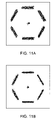
- FIG. 11A is a simulated image produced from the geometric arrangement of FIG. 10 , showing piston and tilt errors between the center and outer segments, of the deformable mirror of the adaptive optics subsystem.
- FIG. 11B is a simulated image from the geometric arrangement of FIG. 10 , showing no piston and tilt errors between the center and outer segments, of the deformable mirror of the adaptive optics subsystem.
- FIGS. 12A and 12B taken together, set forth a flowchart illustrating exemplary operations of the wavefront sensor of the present invention when performing both coarse and fine phase measurement for a given subaperture.
- FIG. 13 is a flow chart illustrating an exemplary mirror correction scheme utilized by the adaptive optic system of FIG. 10 , for controlling the displacement of mirror segments in the system in order to correct for the phase errors measured during wavefront sensing operations.
- the adaptive optics subsystem 115 includes a tilt mirror 117 , a deformable mirror 19 disposed between its source (the mirrors 114 A and 114 B), and also an electronic imaging camera 131 for capturing an image of the nominal point source.
- a beam splitter 121 directs a portion of the light directed to the imaging camera by the mirrors 117 , 119 to a wavefront sensor 123 that measures the phase distortion in the wavefronts of light directed thereto using the novel wavefront sensing method of the present invention.
- a computer 125 cooperates with mirror driver 127 A to control the tilt mirror 117 to stabilize the image of the point source, and cooperates with the mirror driver 127 B to control the deformable mirror 119 so as to compensate for and correcting large phase distortions measured therein, substantially free of the 2 ⁇ phase resolution ambiguity associated with prior art wavefront sensing techniques.
- Long-baseline optical interferometers utilize a well known dispersed fringe technique (see, for example, Applied Optics vol. 35, #16, p. 3002).
- dispersed fringe system the beams from two telescope apertures are combined in the pupil plane and brought to a common focus. If the path lengths from the two apertures are closely matched, there will be interference between the two beams and fringes will be formed. For any given wavelength, this fringe pattern shifts with changing path difference but the pattern repeats for every one wavelength change in path. This is known as a 2 ⁇ phase resolution ambiguity. If this focal spot is spectrally dispersed, then the fringe pattern as a function of wavelength may be recorded. Since the ambiguity in path difference is one wavelength at the measurement wavelength, by measuring at multiple wavelengths, it is possible to extend the unambiguous path difference measurement range very significantly.
- the wavefront sensing method employed in adaptive optics subsystem 115 generally comprises: using each subaperture of modified Hartmann sensor 123 to spatially sample incident light from the input beam and form a (far-field) dispersed spot image with a fringe pattern corresponding to each sample of incident light; and using an image camera 124 as part of sensor 123 to capture the image of the dispersed fringe pattern and an associated image processor 125 to analyze spectral components of the dispersed fringe pattern in order to derive a measure of the local phase distortion in each sample of incident light, in a way which is substantially free of the 2 ⁇ phase error ambiguity characteristic of prior art wavefront sensing techniques.
- each subaperture in the wavefront sensor of the present invention forms a unique image of a spatial sample of incident light. If that subaperture, for example, bridges the gap between the two segments of deformable mirrors 117 , 119 in the adaptive optic subsystem 115 , then a phase step may be introduced into a subaperture. In such a case, the two halves of the subaperture would be analogous to the two apertures of a long baseline interferometer, as disclosed in Applied Optics, Volume 35, No. 16, page 3002, wherein a dispersed fringe analysis technique is disclosed.
- phase step occurs within a subaperture and the image is dispersed, then a very distinctive fringe pattern is formed, and by analyzing this dispersed fringe pattern, the size of the phase step can be determined without 2 ⁇ phase error ambiguity.
- FIG. 3A a distinctive fringe pattern is shown, which closely parallels the simulation of the expected image shown in FIG. 3B from the arrangement of the wavefront sensor of the present invention in FIGS. 4A–4B and 5 .
- the wavefront sensor comprises optical elements 117 that spatially sample incident light and form dispersed spots with a fringe pattern corresponding to samples of the incident light.
- wavefront sensor 123 further comprises electronic imaging device 124 (e.g., CCD camera) for recording the light transmitted through the optical elements 1503 to capture an image of the fringe pattern of such spots.
- the pupil plane is shown at 126 .
- the wavefront sensor 123 further comprises image processor 127 analyzes for analyzing spectral components of the fringe pattern in the image captured by the imaging device 124 so as to derive a measure (that eliminates the 2 ⁇ ambiguity) of the local phase distortions in the samples of incident light.
- the optical elements 117 may comprise a transmission grating 110 (for example, with dimensions one inch square and 3 mm thick) and a lens array 115 .
- the lens array 115 may include epoxy on glass (for example with dimensions one inch in diameter and 6 mm thick). Segment dividers, which illustrate the spatially partitioning of the subapertures of the lens array, are shown by a thick line as, for example, is indicated at 120 .
- the grating direction is shown at 122 .
- the pupil plane is shown at 126 .
- the position of the grating 10 with respect to the lens array 115 may be juxtaposed such that grating 110 is adjacent to the pupil plane 126 .
- the optical elements 117 of the wavefront sensor 123 of FIG. 5 may comprise one or more refractive optical elements (such as prisms) or one or more diffractive optical elements (such as a diffraction grating or hologram) or a combination of the two, e.g., a grism.
- a grism, or Carpenter prism, whose function is schematically illustrated in FIG. 4C is a transmission grating mounted on a prism that together act to disperse incident light (along a predetermined dispersion direction) without deviating a component (its design wavelength) of the incident light.
- the optical elements 117 provide an independent dispersive direction (which is preferably aligned along the direction of the phase step to be measure) for each subaperture.
- Holographic gratings or an array of grism elements provide such independent dispersion directions.
- Optical elements with a singular dispersive direction may be used, but this complicates the analysis for phase steps that ran at an angle relative to the singular dispersion direction.
- the optical elements 117 of the wavefront sensor 100 of FIG. 5 may include a first dispersive element 118 A (which may be a grism or grism array or hologram) that disperses incident light and a second dispersive element 118 B that deviate the dispersed ray bundle formed by the first dispersive element 118 A to produce the fringe pattern for measurement.
- a first dispersive element 118 A which may be a grism or grism array or hologram
- the second dispersive element 118 B may be realized as an array of prism elements, wherein each prism element includes a plurality of sub-elements that have slightly different tilt in the direction perpendicular to the dispersion direction of the first dispersive element 118 A, which deviates the ray bundle formed by the first dispersive element so that the spectral components of the dispersed spot fringe pattern are separated in the image plane of the imaging device.
- first and second dispersive elements 118 A and 118 B of the wavefront sensor 100 may be integrated into a single module.
- FIGS. 5A–8F show the results of a simulation of this arrangement.
- the dispersion is in the vertical direction and covers the range from 0.5 ⁇ m at the bottom to 1.0 ⁇ m at the top.
- Each image is the blur spot formed by a Hartmann lenslet that has been combined with a dispersive element.
- the wavefront sensor 123 of the present invention includes imaging device 124 (e.g., CCD camera or CMOS camera) that captures an image of the fringe pattern distributed along the dispersion direction by the dispersive elements 117 , and image processing device 127 that analyzes the spectral components of the fringe pattern to derive a measure (that eliminates the 2 ⁇ ambiguity) of the local phase distortion in the corresponding sample of incident light.
- the image processing device 127 analyzes the spatial frequency of the spectral components of the fringe pattern to derive a measure (that eliminates the 2 ⁇ ambiguity) of the local phase distortion in the corresponding sample of incident light.
- FIG. 12 illustrates exemplary operations of the image processing device in analyzing the spatial frequency of the spectral components of the fringe pattern to derive a measure (that eliminates the 2 ⁇ ambiguity) of the local phase distortion in the corresponding sample of incident light.
- the wavefront sensor 100 derives a measure of phase distortion without ambiguity (e.g., the 2 ⁇ ambiguity is resolved). For example, a slice through the image of such light distribution along the dispersion direction yields an intensity profile that is exactly analogous to the output of the dispersed fringe sensor. Such a slice produced by a simulation is shown in FIG. 9 .
- the wavefront sensor of the present invention 123 shown in FIGS. 2 through 5 and as described above is preferably operated in two modes.
- the first mode of operation is used when the estimated phase step error is large (e.g., greater than 1 ⁇ 2 wave), and provides a coarse measure of phase distortion without ambiguity (e.g., the 2 ⁇ ambiguity is resolved).
- the second mode of operation is used when the phase step is small (e.g., less than 1 ⁇ 2 wave), and provides a finer measure of such phase distortion.
- slices (along the direction of dispersion) in the image of the fringe pattern are analyzed to yield an estimate of the phase error. This estimate is used to correct the error until the size of the step is reduced below 1 ⁇ 2 wave.
- the second mode of operation is used.
- slices perpendicular to the direction of dispersion
- the measure the phase error with greater accuracy, which is used to further reduce the phase step error. Simulations indicate that measurement of phase step errors of less than 1/50 wave should be possible.
- This one sensor then combines both the coarse and fine phase measurement capability in one monolithic optical instrument.
- FIGS. 12A and 12B illustrate a more detailed description of exemplary operations of the wavefront sensor of the present invention 123 in performing both coarse and fine phase measurement for a given subaperture.
- the optical elements that form the far-field fringe pattern for a given subaperture e.g., dispersion element
- the imaging device 124 captures an image of the fringe pattern (which corresponds to the spectral components of the dispersed far-field spot) for the given aperture.
- image processor 127 may apply image processing techniques (such as filtering, contrast enhancement, etc) to improve the signal-to-noise ratio of the interference fringe therein.
- step 1205 the image processor 127 calculates a two-dimensional gradient of the image produced in step 1203 and derives slope of the fringe pattern from the gradient values. This slope provides the sign of the course estimate of phase step error as derived in step 1217 .
- steps 1207 – 1213 a loop is performed over a predetermined number of slices (that are parallel to the direction of dispersion for the given subaperture) through the image produced in step 1203 , wherein steps 1209 and 1211 are performed for each “parallel” slice.
- steps 1209 and 1211 are performed for each “parallel” slice.
- a fast fourier transform (FFT) is performed on the intensity values of the slice; and, in step 1211 , a maximum value (corresponding to the peak spatial frequency of the spectral components in the fringe pattern) in the FFT of the slice is identified.
- a spatial frequency value is derived from the maximums identified in step 1211 (for example, by calculating the average of such maximums). This spatial frequency value characterizes the spatial frequency of the spectral components in the fringe pattern.
- a course estimate of the phase step error is derived from the sign (identified in step 1205 ) and the spatial frequency value calculated in step 1215 . Because the phase step error is directly proportional to the spatial frequency of the spectral components in the fringe pattern, this operation preferably includes a multiplication of the spatial frequency value (calculated in step 1215 ) by a constant. Note that the 2 ⁇ ambiguity is resolved in this measurement.
- step 1219 the coarse estimate of phase step error is output to a mirror correction routine to correct for this error and the operation of the first mode ends.
- step 1221 it is determined if the second mode of operation (e.g., the phase step error is less than 1 ⁇ 2 wave) for fine phase error measurement should be entered. If not, the operation returns back step 1203 to perform course phase measurement and correction; if so, the operation continues to perform a loop 1223 – 1231 .
- the second mode of operation e.g., the phase step error is less than 1 ⁇ 2 wave
- Loop 1223 – 1231 performs a loop over a predetermined number of slices (that are perpendicular to the direction of dispersion) through the image as produced in step 1203 wherein the operations of steps 1225 , 1227 and 1229 are performed.
- the image processor 127 identifies the location of the centroid of the fringe pattern within the slice.
- the image processor 127 calculates deviation of the centroid (calculated in step 1225 ) from location of a geometric null (e.g., location of a reference centroid measured by the same analysis of the fringe pattern from a reference source). This deviation provides a measure of the phase error for a given spectral component (wavelength) as a function of the wavelength of the spectral component.
- the wavelength corresponding to the phase error measured in step 1227 is identified, and this wavelength is used to convert such phase error to an absolute phase error value for the given spectral component This operation involves mapping the pixel coordinates of the slice to a wavelength.
- mapping is preferably accomplished in a calibration phase, whereby the wavefront sensor 123 is illuminated with a source with predetermined spectral components.
- the image processor 127 identifies such predetermined spectral components in its image plane (pixel coordinates), determines a mapping between pixel coordinates and wavelength, and stores such mapping in persistent storage for subsequent use.
- step 1233 the image processor 127 derives a fine phase step error from the absolute phase errors (step 1229 ) for the slices, for example, by averaging the absolute phase errors.
- step 1235 the image processor 127 outputs the fine phase step error to a mirror correction routine that corrects for the fine phase step error, and returns to the first mode of operation in step 1203 .
- the wavefront sensor of the present invention 123 as described above is preferably used as part of an adaptive optic system as illustrated in FIG. 2 .
- the wavefront sensor 123 measures the phase distortion in the wavefronts of light directed thereto, and operates in conjunction with a computer 125 and mirror drivers to control one or more mirrors (such as tilt mirror 117 and deformable mirror 119 to compensate for the phase distortions (i.e. errors) measured therein.
- FIG. 10 illustrates an exemplary embodiment of an adaptive optic system according to the present invention. It provides a schematic view that shows the geometric arrangement of the apertures of the wavefront sensor overlaid onto the segments of a multi-segmented deformable mirror.
- the bottom layer represents the segments of the deformable mirror. As shown there are seven large hexagons 1100 , with six large hexagons arranged around the seventh, each of which is a mirror, or mirror segment.
- mirror to refer to the overall surface that is composed of individual “mirror segments.” Here it is assumed that the mirror to be phased consists of hexagonal segments, although other shapes also work.
- the top layer 250 represent the apertures of the wavefront sensor 123 .
- a first type of apertures 1115 (referred to as “dispersed Hartmann apertures”) 1115 form far-field spots corresponding to samples of the incident light and disperse the fringe pattern of such spots as discussed above.
- a second type of apertures 1110 (referred to “normal Hartmann aperture”) do not perform dispersion.
- Arranged around the six edges of the center mirror segment are six dispersed Hartmann apertures 1115 that are used to measure the piston difference to adjacent mirror segments from the center mirror segment. Additional dispersed Hartmann subapertures 1115 are located between the centers of the other mirror segments.
- each mirror segment In the center of each mirror segment is a normal Hartmann subaperture 1110 used to measure the tilt of the segment. This single subaperture may be replaced by many smaller subapertures if the segment requires figure measurement or control.
- This hybrid optical element would preferably be fabricated as a single unit with holographic gratings and refractive lenslets. It could be mounted in a retractable holder in a pupil plane of the telescope system. The resulting images would be captured by imaging camera 131 .
- the procedure for aligning and phasing this set of segments begins by using the central subaperture tip and tilt error signals to point the segment correctly.
- the tilt alignment is performed by deforming the mirror segment so that it tilts in the proper direction.
- Phase alignment is performed by moving a piston attached to the back of the segment and changing the height of the segment. The goal is to make all parts of the incoming wave as shown in FIG. 2 reach the mirror segments at the same time and at the same angle. It is here assumed that a suitable reference position for each segment has been defined. Once the tilt error is minimized, the six dispersed sensors 1115 are used to measure the piston differences.
- FIG. 11A shows a simulation of the image formed by this arrangement of subapertures for the case in which the central segment is both tilted and pistoned with respect to the others.
- FIG. 11B shows the case in which the segments are properly phased.
- FIG. 13 illustrates an exemplary mirror correction scheme utilized by the adaptive optic system of FIG. 10 to control displacement of the mirror segments to correct for the phase errors provided by wavefront sensing operations.
- a loop is performed over one or more of the mirror segments of FIG. 10 .
- Step 1305 is performed for each given segment in the loop.
- the estimated phase step errors produced by the wavefront sensor 123 that correspond to the given segment are used to construct a phase error for the given mirror segment in a global coordinate system of the deformable mirror.
- step 1303 ends in step 1303 and operations continue to step 1307 wherein the phase error of the mirror segment(s) calculated in step 1305 , which are represented in the global coordinate system of the deformable mirror, is used to derive segment displacements that best corrects for such phase error (i.e., forms the complex conjugate of such phase errors).
- the improved wavefront sensor 123 and adaptive optic subsystem as described above is preferably used as part of a large aperture space telescope as illustrated in FIG. 2 . Because of the large dynamic range of the wavefront sensor and its ability to perform wavefront measurement without ambiguity, it is ideally suited to performed course adjustment of a large aperture space telescope to thereby correct for large phase steps that are initially present within such systems.
- the wavefront sensor because of the large dynamic measurement range of the wavefront sensor, it can operate effectively in highly turbulent transmission mediums. Moreover, wavefront measurements for all segments can be made simultaneously using a single image of the wavefront.
Abstract
Description
Claims (5)
Priority Applications (2)
| Application Number | Priority Date | Filing Date | Title |
|---|---|---|---|
| US10/647,908 US7161128B2 (en) | 2000-07-14 | 2003-08-25 | Optical instrument employing a wavefront sensor capable of coarse and fine phase measurement capabilities during first and second modes of operation |
| US11/647,511 US20070194207A1 (en) | 2000-07-14 | 2006-12-28 | Method and apparatus for wavefront measurement that resolves the 2-pi ambiguity in such measurement and adaptive optics systems utilizing same |
Applications Claiming Priority (3)
| Application Number | Priority Date | Filing Date | Title |
|---|---|---|---|
| US21819000P | 2000-07-14 | 2000-07-14 | |
| US09/906,388 US6630656B2 (en) | 2000-07-14 | 2001-07-16 | Method and apparatus for wavefront measurement that resolves the 2-π ambiguity in such measurement and adaptive optics systems utilizing same |
| US10/647,908 US7161128B2 (en) | 2000-07-14 | 2003-08-25 | Optical instrument employing a wavefront sensor capable of coarse and fine phase measurement capabilities during first and second modes of operation |
Related Parent Applications (1)
| Application Number | Title | Priority Date | Filing Date |
|---|---|---|---|
| US09/906,388 Continuation US6630656B2 (en) | 2000-07-14 | 2001-07-16 | Method and apparatus for wavefront measurement that resolves the 2-π ambiguity in such measurement and adaptive optics systems utilizing same |
Related Child Applications (1)
| Application Number | Title | Priority Date | Filing Date |
|---|---|---|---|
| US11/647,511 Continuation US20070194207A1 (en) | 2000-07-14 | 2006-12-28 | Method and apparatus for wavefront measurement that resolves the 2-pi ambiguity in such measurement and adaptive optics systems utilizing same |
Publications (2)
| Publication Number | Publication Date |
|---|---|
| US20050098707A1 US20050098707A1 (en) | 2005-05-12 |
| US7161128B2 true US7161128B2 (en) | 2007-01-09 |
Family
ID=34555224
Family Applications (2)
| Application Number | Title | Priority Date | Filing Date |
|---|---|---|---|
| US10/647,908 Expired - Fee Related US7161128B2 (en) | 2000-07-14 | 2003-08-25 | Optical instrument employing a wavefront sensor capable of coarse and fine phase measurement capabilities during first and second modes of operation |
| US11/647,511 Abandoned US20070194207A1 (en) | 2000-07-14 | 2006-12-28 | Method and apparatus for wavefront measurement that resolves the 2-pi ambiguity in such measurement and adaptive optics systems utilizing same |
Family Applications After (1)
| Application Number | Title | Priority Date | Filing Date |
|---|---|---|---|
| US11/647,511 Abandoned US20070194207A1 (en) | 2000-07-14 | 2006-12-28 | Method and apparatus for wavefront measurement that resolves the 2-pi ambiguity in such measurement and adaptive optics systems utilizing same |
Country Status (1)
| Country | Link |
|---|---|
| US (2) | US7161128B2 (en) |
Cited By (5)
| Publication number | Priority date | Publication date | Assignee | Title |
|---|---|---|---|---|
| US20070158529A1 (en) * | 2006-01-11 | 2007-07-12 | Smith Mark A | Closed loop compensation system and method |
| US20070176077A1 (en) * | 2006-01-30 | 2007-08-02 | Science Applications International Corporation | System and method for correction of turbulence effects on laser or other transmission |
| US7352470B1 (en) * | 2002-07-26 | 2008-04-01 | Lockheed Martin Corporation | Fourier transform spectrometry with a single-aperture interferometer |
| US20110066740A1 (en) * | 2009-09-14 | 2011-03-17 | Honeywell International Inc. | Interferometric precise timing distribution with a precision phase detector |
| US9329381B1 (en) * | 2009-12-10 | 2016-05-03 | Nutronics, Inc. | Target feature integrated laser field and amplifier compensation system |
Families Citing this family (12)
| Publication number | Priority date | Publication date | Assignee | Title |
|---|---|---|---|---|
| US7862188B2 (en) * | 2005-07-01 | 2011-01-04 | Flir Systems, Inc. | Image detection improvement via compensatory high frequency motions of an undedicated mirror |
| US9298014B2 (en) * | 2005-07-01 | 2016-03-29 | Flir Systems, Inc. | Image stabilization system |
| ES2325698B1 (en) * | 2006-01-20 | 2010-10-19 | Universidad De La Laguna | PHASE CHAMBER FOR THE MEASUREMENT OF DISTANCES AND ABERRATIONS OF FRONT WAVE IN VARIOUS ENVIRONMENTS THROUGH SLICE DE FOURIER. |
| JP5146937B2 (en) * | 2008-04-07 | 2013-02-20 | 富士通株式会社 | Optical wavefront control system and optical wavefront control method |
| US10132925B2 (en) | 2010-09-15 | 2018-11-20 | Ascentia Imaging, Inc. | Imaging, fabrication and measurement systems and methods |
| WO2012037343A1 (en) * | 2010-09-15 | 2012-03-22 | Ascentia Imaging, Inc. | Imaging, fabrication, and measurement systems and methods |
| WO2013103725A1 (en) | 2012-01-03 | 2013-07-11 | Ascentia Imaging, Inc. | Coded localization systems, methods and apparatus |
| US9739864B2 (en) | 2012-01-03 | 2017-08-22 | Ascentia Imaging, Inc. | Optical guidance systems and methods using mutually distinct signal-modifying |
| CN103256990B (en) * | 2012-06-18 | 2016-05-04 | 太原理工大学 | A kind of diffraction pyramid wave-front sensor |
| ES2458919B2 (en) * | 2013-07-17 | 2016-04-06 | Universidade De Santiago De Compostela | Wavefront measurement device and procedure |
| US10126114B2 (en) | 2015-05-21 | 2018-11-13 | Ascentia Imaging, Inc. | Angular localization system, associated repositionable mechanical structure, and associated method |
| FR3086488B1 (en) * | 2018-09-20 | 2020-09-18 | Centre Nat Rech Scient | PROCESS FOR ACQUIRING AN IMAGE WITH ADAPTIVE OPTICS |
Citations (25)
| Publication number | Priority date | Publication date | Assignee | Title |
|---|---|---|---|---|
| US4141652A (en) | 1977-11-25 | 1979-02-27 | Adaptive Optics Associates, Inc. | Sensor system for detecting wavefront distortion in a return beam of light |
| US4248504A (en) | 1978-12-08 | 1981-02-03 | Itek Corporation | Piezoelectric wavefront modulator |
| US4257686A (en) | 1978-12-14 | 1981-03-24 | Itek Corporation | Multiple layer piezoelectric wavefront modulator |
| US4399356A (en) | 1981-01-19 | 1983-08-16 | Adaptive Optics Associates, Inc. | Optical wavefront sensing system |
| US4474467A (en) | 1981-12-28 | 1984-10-02 | Itek Corporation | Wavefront sensor using a surface acoustic wave diffraction grating |
| US4696573A (en) | 1985-07-03 | 1987-09-29 | Itek Corporation | Dual shear wavefront sensor |
| US4725138A (en) | 1985-05-22 | 1988-02-16 | Adaptive Optics Associates Incorporated | Optical wavefront sensing system |
| US4737621A (en) | 1985-12-06 | 1988-04-12 | Adaptive Optics Assoc., Inc. | Integrated adaptive optical wavefront sensing and compensating system |
| US5093563A (en) | 1987-02-05 | 1992-03-03 | Hughes Aircraft Company | Electronically phased detector arrays for optical imaging |
| US5113064A (en) | 1991-03-06 | 1992-05-12 | The United States Of America As Represented By The Administrator Of The National Aeronautics And Space Administration | Method and apparatus for phasing segmented mirror arrays |
| US5317389A (en) | 1989-06-12 | 1994-05-31 | California Institute Of Technology | Method and apparatus for white-light dispersed-fringe interferometric measurement of corneal topography |
| US5493391A (en) | 1994-07-11 | 1996-02-20 | Sandia Corporation | One dimensional wavefront distortion sensor comprising a lens array system |
| US5629765A (en) | 1995-12-15 | 1997-05-13 | Adaptive Optics Associates, Inc. | Wavefront measuring system with integral geometric reference (IGR) |
| US5798878A (en) | 1996-04-18 | 1998-08-25 | Mitsubishi Denki Kabushiki Kaisha | Shape control apparatus for reflecting mirrors |
| US5864381A (en) | 1996-07-10 | 1999-01-26 | Sandia Corporation | Automated pupil remapping with binary optics |
| US5912731A (en) | 1997-12-04 | 1999-06-15 | Trw Inc. | Hartmann-type optical wavefront sensor |
| US5936720A (en) | 1996-07-10 | 1999-08-10 | Neal; Daniel R. | Beam characterization by wavefront sensor |
| US6052180A (en) | 1996-07-10 | 2000-04-18 | Wavefront Sciences, Inc. | Apparatus and method for characterizing pulsed light beams |
| US6108121A (en) | 1998-03-24 | 2000-08-22 | The Board Of Trustees Of The Leland Stanford Junior University | Micromachined high reflectance deformable mirror |
| US6113242A (en) | 1999-01-15 | 2000-09-05 | The United States Of America As Represented By The Secretary Of The Air Force | Active edge controlled optical quality membrane mirror |
| US6130419A (en) | 1996-07-10 | 2000-10-10 | Wavefront Sciences, Inc. | Fixed mount wavefront sensor |
| US6163381A (en) | 1999-02-24 | 2000-12-19 | Trw Inc. | Dual sensor atmospheric correction system |
| US6184974B1 (en) | 1999-07-01 | 2001-02-06 | Wavefront Sciences, Inc. | Apparatus and method for evaluating a target larger than a measuring aperture of a sensor |
| US6278100B1 (en) | 1999-05-04 | 2001-08-21 | Ball Aerospace & Technologies Corp. | Synthetic guide star for on-orbit assembly and configuration of large earth remote sensing optical systems |
| US6649895B1 (en) * | 2000-07-14 | 2003-11-18 | Adaptive Optics Associates, Inc. | Dispersed Hartmann sensor and method for mirror segment alignment and phasing |
Family Cites Families (1)
| Publication number | Priority date | Publication date | Assignee | Title |
|---|---|---|---|---|
| US5629785A (en) * | 1995-05-04 | 1997-05-13 | Motorola, Inc. | Polymer dispersed liquid crystal display device with asymmetric optical diffuser |
-
2003
- 2003-08-25 US US10/647,908 patent/US7161128B2/en not_active Expired - Fee Related
-
2006
- 2006-12-28 US US11/647,511 patent/US20070194207A1/en not_active Abandoned
Patent Citations (26)
| Publication number | Priority date | Publication date | Assignee | Title |
|---|---|---|---|---|
| US4141652A (en) | 1977-11-25 | 1979-02-27 | Adaptive Optics Associates, Inc. | Sensor system for detecting wavefront distortion in a return beam of light |
| US4248504A (en) | 1978-12-08 | 1981-02-03 | Itek Corporation | Piezoelectric wavefront modulator |
| US4257686A (en) | 1978-12-14 | 1981-03-24 | Itek Corporation | Multiple layer piezoelectric wavefront modulator |
| US4399356A (en) | 1981-01-19 | 1983-08-16 | Adaptive Optics Associates, Inc. | Optical wavefront sensing system |
| US4474467A (en) | 1981-12-28 | 1984-10-02 | Itek Corporation | Wavefront sensor using a surface acoustic wave diffraction grating |
| US4725138A (en) | 1985-05-22 | 1988-02-16 | Adaptive Optics Associates Incorporated | Optical wavefront sensing system |
| US4696573A (en) | 1985-07-03 | 1987-09-29 | Itek Corporation | Dual shear wavefront sensor |
| US4737621A (en) | 1985-12-06 | 1988-04-12 | Adaptive Optics Assoc., Inc. | Integrated adaptive optical wavefront sensing and compensating system |
| US5093563A (en) | 1987-02-05 | 1992-03-03 | Hughes Aircraft Company | Electronically phased detector arrays for optical imaging |
| US5317389A (en) | 1989-06-12 | 1994-05-31 | California Institute Of Technology | Method and apparatus for white-light dispersed-fringe interferometric measurement of corneal topography |
| US5113064A (en) | 1991-03-06 | 1992-05-12 | The United States Of America As Represented By The Administrator Of The National Aeronautics And Space Administration | Method and apparatus for phasing segmented mirror arrays |
| US5493391A (en) | 1994-07-11 | 1996-02-20 | Sandia Corporation | One dimensional wavefront distortion sensor comprising a lens array system |
| US5629765A (en) | 1995-12-15 | 1997-05-13 | Adaptive Optics Associates, Inc. | Wavefront measuring system with integral geometric reference (IGR) |
| WO1997021989A1 (en) | 1995-12-15 | 1997-06-19 | Adaptive Optics Associates, Inc. | Wavefront measuring system with integral geometric reference (igr) |
| US5798878A (en) | 1996-04-18 | 1998-08-25 | Mitsubishi Denki Kabushiki Kaisha | Shape control apparatus for reflecting mirrors |
| US6130419A (en) | 1996-07-10 | 2000-10-10 | Wavefront Sciences, Inc. | Fixed mount wavefront sensor |
| US5864381A (en) | 1996-07-10 | 1999-01-26 | Sandia Corporation | Automated pupil remapping with binary optics |
| US5936720A (en) | 1996-07-10 | 1999-08-10 | Neal; Daniel R. | Beam characterization by wavefront sensor |
| US6052180A (en) | 1996-07-10 | 2000-04-18 | Wavefront Sciences, Inc. | Apparatus and method for characterizing pulsed light beams |
| US5912731A (en) | 1997-12-04 | 1999-06-15 | Trw Inc. | Hartmann-type optical wavefront sensor |
| US6108121A (en) | 1998-03-24 | 2000-08-22 | The Board Of Trustees Of The Leland Stanford Junior University | Micromachined high reflectance deformable mirror |
| US6113242A (en) | 1999-01-15 | 2000-09-05 | The United States Of America As Represented By The Secretary Of The Air Force | Active edge controlled optical quality membrane mirror |
| US6163381A (en) | 1999-02-24 | 2000-12-19 | Trw Inc. | Dual sensor atmospheric correction system |
| US6278100B1 (en) | 1999-05-04 | 2001-08-21 | Ball Aerospace & Technologies Corp. | Synthetic guide star for on-orbit assembly and configuration of large earth remote sensing optical systems |
| US6184974B1 (en) | 1999-07-01 | 2001-02-06 | Wavefront Sciences, Inc. | Apparatus and method for evaluating a target larger than a measuring aperture of a sensor |
| US6649895B1 (en) * | 2000-07-14 | 2003-11-18 | Adaptive Optics Associates, Inc. | Dispersed Hartmann sensor and method for mirror segment alignment and phasing |
Non-Patent Citations (11)
| Title |
|---|
| Chapter 1 of AOA's WaveScope System User Manual entitled "System Overview" by Adaptive Optics Associates, Inc., http://www.aoainc.com/technologies/adaptiveandmicrooptics/wavescope/CHAP6.html, 2001, pp. 1-5. |
| Chapter 4 of AOA's WaveScope System User Manual entitled "Alignment" by Adaptive Optics Associates, Inc., http://www.aoainc.com/technologies/adaptiveandmicroptics/wavescope/Alignment.htm, 2001, pp. 1-25. |
| Chapter 5 of AOA's WaveScope System User Manual entitled "Calibration" by Adaptive Optics Associates, Inc., http://www.aoainc.com/technologies/adaptiveandmicrooptics/wavescope/Calibration., 2001, pp. 1-23. |
| Chapter 8 of AOA's WaveScope System User Manual entitled "Basic Theory of Hartmann Sensing" by Adaptive Optics Associates, Inc., http://www.aoainc.com/technologies/adaptiveandmicrooptics/wavescope/CHAP2.html, 2001, pp. 1-5. |
| Search Report for International Application No. PCT/US01/22281, 2001. |
| Textbook entitled "Introduction to Adaptive Optics" by Tyson, Tutorial Texts in Optical Engineering, SPIE Press, vol. TT41, 2000, pp. 1-117. |
| Textbook entitled "Introduction to Wavefront Sensors" by Geary, Tutorial Texts in Optical Engineering, vol. TT18, SPIE Optical Engineering Press, 1995, pp. 1-169. |
| Web-based publication entitled "Absolute Distance Interferometry" by the Institute of Physics at E.M. Arndt University, http://www2.physik.uni-greifswald.de/laser/forschung/adj<SUB>-</SUB>eng.html, 2001, pp. 1-3. |
| Web-based publication entitled "Interferometer satellite synthetic aperture radar and its application to the observation of Greenland ice sheet motion" by Frick, http://www.icg.tu-graz.ac.at/Education/Diplomarbeiten/1996/frick, 1996, pp. 1-2. |
| Web-based Publication entitled "Low-Cost Adaptive Optics" by University of Edinburgh et al., http://op.ph.ic.ac.uk/ao/locado.html, Mar. 1999, pp. 1-3. |
| Web-based Publication entitled "Two-frequency phase-shifting projection moire topography" by Kim et al., http://www.spie.org/web/abstracts/3500/3520.html, vol. 3520, 1998, pp. 36-42. |
Cited By (12)
| Publication number | Priority date | Publication date | Assignee | Title |
|---|---|---|---|---|
| US7352470B1 (en) * | 2002-07-26 | 2008-04-01 | Lockheed Martin Corporation | Fourier transform spectrometry with a single-aperture interferometer |
| US20070158529A1 (en) * | 2006-01-11 | 2007-07-12 | Smith Mark A | Closed loop compensation system and method |
| US7381934B2 (en) * | 2006-01-11 | 2008-06-03 | Xinetics, Inc. | Closed loop compensation system and method for a deformable mirror |
| US20070176077A1 (en) * | 2006-01-30 | 2007-08-02 | Science Applications International Corporation | System and method for correction of turbulence effects on laser or other transmission |
| US7402785B2 (en) * | 2006-01-30 | 2008-07-22 | Science Applications International Corporation | System and method for correction of turbulence effects on laser or other transmission |
| US20110066740A1 (en) * | 2009-09-14 | 2011-03-17 | Honeywell International Inc. | Interferometric precise timing distribution with a precision phase detector |
| US8909804B2 (en) * | 2009-09-14 | 2014-12-09 | Honeywell International Inc. | Interferometric precise timing distribution with a precision phase detector |
| US20150023460A1 (en) * | 2009-09-14 | 2015-01-22 | Honeywell International Inc. | Interferometric precise timing distribution with a precision phase detector |
| US9621335B2 (en) * | 2009-09-14 | 2017-04-11 | Honeywell International Inc. | Interferometric precise timing distribution with a precision phase detector |
| US9329381B1 (en) * | 2009-12-10 | 2016-05-03 | Nutronics, Inc. | Target feature integrated laser field and amplifier compensation system |
| US9329081B1 (en) * | 2009-12-10 | 2016-05-03 | Nutronics, Inc. | Target feature integrated laser phase compensation system |
| US9360663B1 (en) * | 2009-12-10 | 2016-06-07 | Jeffrey D Barchers | Target feature integrated laser phase and amplifier compensation system |
Also Published As
| Publication number | Publication date |
|---|---|
| US20050098707A1 (en) | 2005-05-12 |
| US20070194207A1 (en) | 2007-08-23 |
Similar Documents
| Publication | Publication Date | Title |
|---|---|---|
| US20070194207A1 (en) | Method and apparatus for wavefront measurement that resolves the 2-pi ambiguity in such measurement and adaptive optics systems utilizing same | |
| US6630656B2 (en) | Method and apparatus for wavefront measurement that resolves the 2-π ambiguity in such measurement and adaptive optics systems utilizing same | |
| Millerd et al. | Pixelated phase-mask dynamic interferometers | |
| EP0866956B1 (en) | Wavefront measuring system with integral geometric reference (igr) | |
| US5777736A (en) | High etendue imaging fourier transform spectrometer | |
| US9046412B2 (en) | Compact interferometer spectrometer | |
| US6351307B1 (en) | Combined dispersive/interference spectroscopy for producing a vector spectrum | |
| US7283251B1 (en) | Black fringe wavefront sensor | |
| US6924899B2 (en) | System for measuring wavefront tilt in optical systems and method of calibrating wavefront sensors | |
| US5350911A (en) | Wavefront error estimation derived from observation of arbitrary unknown extended scenes | |
| CN100573038C (en) | The two-dimension chromatic dispersion fringe analysis method that is used for absolute distance measurement | |
| EP0518107A1 (en) | Piston error estimation method for segmented aperture optical systems while observing arbitrary unknown extended scenes | |
| Harlander et al. | Field-widened spatial heterodyne spectroscopy: correcting for optical defects and new vacuum ultraviolet performance tests | |
| US7167249B1 (en) | High efficiency spectral imager | |
| JPH0321053B2 (en) | ||
| CN108362381B (en) | Wide-field large-aperture spatial heterodyne interference imaging spectrometer | |
| RU2313070C2 (en) | Interference spectrometer | |
| US20220244519A1 (en) | Telescopes | |
| Mazzoleni et al. | Design and performances of the Shack-Hartmann sensor within the Active Phasing Experiment | |
| US20110134415A1 (en) | Method for correcting a wave front analyser and analyser implementing said method | |
| Smith et al. | Coarse phasing of segmented mirrors using a dispersed fringe sensor | |
| CN105910630B (en) | Optical path difference measurement method and its device based on the modulation of space optical path difference | |
| Martinez et al. | Mach-Zehnder wavefront sensor for phasing of segmented telescopes | |
| CN113447125B (en) | Multi-resolution mode interference spectrum system | |
| Li et al. | Diagnosing piston error from hyperspectral image with extended scene |
Legal Events
| Date | Code | Title | Description |
|---|---|---|---|
| AS | Assignment |
Owner name: MORGAN STANLEY & CO. INCORPORATED, NEW YORK Free format text: FIRST LIEN IP SECURITY AGREEMENT;ASSIGNORS:METROLOGIC INSTRUMENTS, INC.;METEOR HOLDING CORP.;OMNIPLANAR, INC.;REEL/FRAME:018942/0315 Effective date: 20061221 Owner name: MORGAN STANLEY & CO. INCORPORATED, NEW YORK Free format text: SECOND LIEN IP SECURITY AGREEMENT;ASSIGNORS:METROLOGIC INSTRUMENTS, INC.;METEOR HOLDING CORP.;OMNIPLANAR, INC.;REEL/FRAME:018942/0671 Effective date: 20061221 Owner name: MORGAN STANLEY & CO. INCORPORATED,NEW YORK Free format text: FIRST LIEN IP SECURITY AGREEMENT;ASSIGNORS:METROLOGIC INSTRUMENTS, INC.;METEOR HOLDING CORP.;OMNIPLANAR, INC.;REEL/FRAME:018942/0315 Effective date: 20061221 Owner name: MORGAN STANLEY & CO. INCORPORATED,NEW YORK Free format text: SECOND LIEN IP SECURITY AGREEMENT;ASSIGNORS:METROLOGIC INSTRUMENTS, INC.;METEOR HOLDING CORP.;OMNIPLANAR, INC.;REEL/FRAME:018942/0671 Effective date: 20061221 |
|
| FEPP | Fee payment procedure |
Free format text: PAYOR NUMBER ASSIGNED (ORIGINAL EVENT CODE: ASPN); ENTITY STATUS OF PATENT OWNER: LARGE ENTITY |
|
| AS | Assignment |
Owner name: METROLOGIC INSTRUMENTS, INC., NEW JERSEY Free format text: FIRST LIEN INTELLECTUAL PROPERTY SECURITY AGREEMENT RELEASE;ASSIGNOR:MORGAN STANLEY & CO. INCORPORATED;REEL/FRAME:023085/0754 Effective date: 20080701 Owner name: METEOR HOLDING CORPORATION, NEW JERSEY Free format text: FIRST LIEN INTELLECTUAL PROPERTY SECURITY AGREEMENT RELEASE;ASSIGNOR:MORGAN STANLEY & CO. INCORPORATED;REEL/FRAME:023085/0754 Effective date: 20080701 Owner name: OMNIPLANAR, INC., NEW JERSEY Free format text: FIRST LIEN INTELLECTUAL PROPERTY SECURITY AGREEMENT RELEASE;ASSIGNOR:MORGAN STANLEY & CO. INCORPORATED;REEL/FRAME:023085/0754 Effective date: 20080701 Owner name: METROLOGIC INSTRUMENTS, INC., NEW JERSEY Free format text: SECOND LIEN INTELLECTUAL PROPERTY SECURITY AGREEMENT RELEASE;ASSIGNOR:MORGAN STANLEY & CO. INCORPORATED;REEL/FRAME:023085/0809 Effective date: 20080701 Owner name: METEOR HOLDING CORPORATION, NEW JERSEY Free format text: SECOND LIEN INTELLECTUAL PROPERTY SECURITY AGREEMENT RELEASE;ASSIGNOR:MORGAN STANLEY & CO. INCORPORATED;REEL/FRAME:023085/0809 Effective date: 20080701 Owner name: OMNIPLANAR, INC., NEW JERSEY Free format text: SECOND LIEN INTELLECTUAL PROPERTY SECURITY AGREEMENT RELEASE;ASSIGNOR:MORGAN STANLEY & CO. INCORPORATED;REEL/FRAME:023085/0809 Effective date: 20080701 Owner name: METROLOGIC INSTRUMENTS, INC.,NEW JERSEY Free format text: FIRST LIEN INTELLECTUAL PROPERTY SECURITY AGREEMENT RELEASE;ASSIGNOR:MORGAN STANLEY & CO. INCORPORATED;REEL/FRAME:023085/0754 Effective date: 20080701 Owner name: METEOR HOLDING CORPORATION,NEW JERSEY Free format text: FIRST LIEN INTELLECTUAL PROPERTY SECURITY AGREEMENT RELEASE;ASSIGNOR:MORGAN STANLEY & CO. INCORPORATED;REEL/FRAME:023085/0754 Effective date: 20080701 Owner name: OMNIPLANAR, INC.,NEW JERSEY Free format text: FIRST LIEN INTELLECTUAL PROPERTY SECURITY AGREEMENT RELEASE;ASSIGNOR:MORGAN STANLEY & CO. INCORPORATED;REEL/FRAME:023085/0754 Effective date: 20080701 Owner name: METROLOGIC INSTRUMENTS, INC.,NEW JERSEY Free format text: SECOND LIEN INTELLECTUAL PROPERTY SECURITY AGREEMENT RELEASE;ASSIGNOR:MORGAN STANLEY & CO. INCORPORATED;REEL/FRAME:023085/0809 Effective date: 20080701 Owner name: METEOR HOLDING CORPORATION,NEW JERSEY Free format text: SECOND LIEN INTELLECTUAL PROPERTY SECURITY AGREEMENT RELEASE;ASSIGNOR:MORGAN STANLEY & CO. INCORPORATED;REEL/FRAME:023085/0809 Effective date: 20080701 Owner name: OMNIPLANAR, INC.,NEW JERSEY Free format text: SECOND LIEN INTELLECTUAL PROPERTY SECURITY AGREEMENT RELEASE;ASSIGNOR:MORGAN STANLEY & CO. INCORPORATED;REEL/FRAME:023085/0809 Effective date: 20080701 |
|
| AS | Assignment |
Owner name: NORTHROP GRUMMAN SYSTEMS CORPORATION,CALIFORNIA Free format text: ASSIGNMENT OF ASSIGNORS INTEREST;ASSIGNOR:NORTHROP GRUMMAN SPACE & MISSION SYSTEMS CORP.;REEL/FRAME:023915/0446 Effective date: 20091210 Owner name: NORTHROP GRUMMAN SYSTEMS CORPORATION, CALIFORNIA Free format text: ASSIGNMENT OF ASSIGNORS INTEREST;ASSIGNOR:NORTHROP GRUMMAN SPACE & MISSION SYSTEMS CORP.;REEL/FRAME:023915/0446 Effective date: 20091210 |
|
| FPAY | Fee payment |
Year of fee payment: 4 |
|
| SULP | Surcharge for late payment | ||
| FPAY | Fee payment |
Year of fee payment: 8 |
|
| FEPP | Fee payment procedure |
Free format text: MAINTENANCE FEE REMINDER MAILED (ORIGINAL EVENT CODE: REM.); ENTITY STATUS OF PATENT OWNER: LARGE ENTITY |
|
| LAPS | Lapse for failure to pay maintenance fees |
Free format text: PATENT EXPIRED FOR FAILURE TO PAY MAINTENANCE FEES (ORIGINAL EVENT CODE: EXP.); ENTITY STATUS OF PATENT OWNER: LARGE ENTITY |
|
| STCH | Information on status: patent discontinuation |
Free format text: PATENT EXPIRED DUE TO NONPAYMENT OF MAINTENANCE FEES UNDER 37 CFR 1.362 |
|
| FP | Lapsed due to failure to pay maintenance fee |
Effective date: 20190109 |