US7161319B2 - Movable barrier operator having serial data communication - Google Patents
Movable barrier operator having serial data communication Download PDFInfo
- Publication number
- US7161319B2 US7161319B2 US10/717,263 US71726303A US7161319B2 US 7161319 B2 US7161319 B2 US 7161319B2 US 71726303 A US71726303 A US 71726303A US 7161319 B2 US7161319 B2 US 7161319B2
- Authority
- US
- United States
- Prior art keywords
- garage door
- microcontroller
- door opener
- drive unit
- light
- Prior art date
- Legal status (The legal status is an assumption and is not a legal conclusion. Google has not performed a legal analysis and makes no representation as to the accuracy of the status listed.)
- Expired - Lifetime
Links
- 230000004888 barrier function Effects 0.000 title abstract description 15
- 239000004020 conductor Substances 0.000 claims 4
- 238000005286 illumination Methods 0.000 abstract description 12
- CJOBVZJTOIVNNF-UHFFFAOYSA-N cadmium sulfide Chemical compound [Cd]=S CJOBVZJTOIVNNF-UHFFFAOYSA-N 0.000 description 5
- 229910052980 cadmium sulfide Inorganic materials 0.000 description 5
- 239000003990 capacitor Substances 0.000 description 5
- 230000008859 change Effects 0.000 description 4
- 238000010586 diagram Methods 0.000 description 4
- 230000005855 radiation Effects 0.000 description 4
- 238000001514 detection method Methods 0.000 description 3
- 230000000694 effects Effects 0.000 description 3
- 230000008901 benefit Effects 0.000 description 2
- 238000012986 modification Methods 0.000 description 2
- 230000004048 modification Effects 0.000 description 2
- 230000004075 alteration Effects 0.000 description 1
- 230000005540 biological transmission Effects 0.000 description 1
- 230000002950 deficient Effects 0.000 description 1
- 230000001934 delay Effects 0.000 description 1
- 230000007246 mechanism Effects 0.000 description 1
- 230000011664 signaling Effects 0.000 description 1
Images


Classifications
-
- G—PHYSICS
- G07—CHECKING-DEVICES
- G07C—TIME OR ATTENDANCE REGISTERS; REGISTERING OR INDICATING THE WORKING OF MACHINES; GENERATING RANDOM NUMBERS; VOTING OR LOTTERY APPARATUS; ARRANGEMENTS, SYSTEMS OR APPARATUS FOR CHECKING NOT PROVIDED FOR ELSEWHERE
- G07C9/00—Individual registration on entry or exit
- G07C9/00174—Electronically operated locks; Circuits therefor; Nonmechanical keys therefor, e.g. passive or active electrical keys or other data carriers without mechanical keys
- G07C9/00182—Electronically operated locks; Circuits therefor; Nonmechanical keys therefor, e.g. passive or active electrical keys or other data carriers without mechanical keys operated with unidirectional data transmission between data carrier and locks
-
- E—FIXED CONSTRUCTIONS
- E05—LOCKS; KEYS; WINDOW OR DOOR FITTINGS; SAFES
- E05F—DEVICES FOR MOVING WINGS INTO OPEN OR CLOSED POSITION; CHECKS FOR WINGS; WING FITTINGS NOT OTHERWISE PROVIDED FOR, CONCERNED WITH THE FUNCTIONING OF THE WING
- E05F15/00—Power-operated mechanisms for wings
- E05F15/60—Power-operated mechanisms for wings using electrical actuators
- E05F15/603—Power-operated mechanisms for wings using electrical actuators using rotary electromotors
- E05F15/665—Power-operated mechanisms for wings using electrical actuators using rotary electromotors for vertically-sliding wings
- E05F15/668—Power-operated mechanisms for wings using electrical actuators using rotary electromotors for vertically-sliding wings for overhead wings
-
- E—FIXED CONSTRUCTIONS
- E05—LOCKS; KEYS; WINDOW OR DOOR FITTINGS; SAFES
- E05F—DEVICES FOR MOVING WINGS INTO OPEN OR CLOSED POSITION; CHECKS FOR WINGS; WING FITTINGS NOT OTHERWISE PROVIDED FOR, CONCERNED WITH THE FUNCTIONING OF THE WING
- E05F15/00—Power-operated mechanisms for wings
-
- E—FIXED CONSTRUCTIONS
- E05—LOCKS; KEYS; WINDOW OR DOOR FITTINGS; SAFES
- E05F—DEVICES FOR MOVING WINGS INTO OPEN OR CLOSED POSITION; CHECKS FOR WINGS; WING FITTINGS NOT OTHERWISE PROVIDED FOR, CONCERNED WITH THE FUNCTIONING OF THE WING
- E05F15/00—Power-operated mechanisms for wings
- E05F15/40—Safety devices, e.g. detection of obstructions or end positions
-
- E—FIXED CONSTRUCTIONS
- E05—LOCKS; KEYS; WINDOW OR DOOR FITTINGS; SAFES
- E05F—DEVICES FOR MOVING WINGS INTO OPEN OR CLOSED POSITION; CHECKS FOR WINGS; WING FITTINGS NOT OTHERWISE PROVIDED FOR, CONCERNED WITH THE FUNCTIONING OF THE WING
- E05F15/00—Power-operated mechanisms for wings
- E05F15/70—Power-operated mechanisms for wings with automatic actuation
- E05F15/77—Power-operated mechanisms for wings with automatic actuation using wireless control
- E05F15/78—Power-operated mechanisms for wings with automatic actuation using wireless control using light beams
-
- E—FIXED CONSTRUCTIONS
- E05—LOCKS; KEYS; WINDOW OR DOOR FITTINGS; SAFES
- E05Y—INDEXING SCHEME RELATING TO HINGES OR OTHER SUSPENSION DEVICES FOR DOORS, WINDOWS OR WINGS AND DEVICES FOR MOVING WINGS INTO OPEN OR CLOSED POSITION, CHECKS FOR WINGS AND WING FITTINGS NOT OTHERWISE PROVIDED FOR, CONCERNED WITH THE FUNCTIONING OF THE WING
- E05Y2400/00—Electronic control; Power supply; Power or signal transmission; User interfaces
- E05Y2400/80—User interfaces
-
- E—FIXED CONSTRUCTIONS
- E05—LOCKS; KEYS; WINDOW OR DOOR FITTINGS; SAFES
- E05Y—INDEXING SCHEME RELATING TO HINGES OR OTHER SUSPENSION DEVICES FOR DOORS, WINDOWS OR WINGS AND DEVICES FOR MOVING WINGS INTO OPEN OR CLOSED POSITION, CHECKS FOR WINGS AND WING FITTINGS NOT OTHERWISE PROVIDED FOR, CONCERNED WITH THE FUNCTIONING OF THE WING
- E05Y2800/00—Details, accessories and auxiliary operations not otherwise provided for
- E05Y2800/10—Additional functions
- E05Y2800/106—Lighting
-
- E—FIXED CONSTRUCTIONS
- E05—LOCKS; KEYS; WINDOW OR DOOR FITTINGS; SAFES
- E05Y—INDEXING SCHEME RELATING TO HINGES OR OTHER SUSPENSION DEVICES FOR DOORS, WINDOWS OR WINGS AND DEVICES FOR MOVING WINGS INTO OPEN OR CLOSED POSITION, CHECKS FOR WINGS AND WING FITTINGS NOT OTHERWISE PROVIDED FOR, CONCERNED WITH THE FUNCTIONING OF THE WING
- E05Y2900/00—Application of doors, windows, wings or fittings thereof
- E05Y2900/10—Application of doors, windows, wings or fittings thereof for buildings or parts thereof
- E05Y2900/106—Application of doors, windows, wings or fittings thereof for buildings or parts thereof for garages
-
- G—PHYSICS
- G07—CHECKING-DEVICES
- G07C—TIME OR ATTENDANCE REGISTERS; REGISTERING OR INDICATING THE WORKING OF MACHINES; GENERATING RANDOM NUMBERS; VOTING OR LOTTERY APPARATUS; ARRANGEMENTS, SYSTEMS OR APPARATUS FOR CHECKING NOT PROVIDED FOR ELSEWHERE
- G07C9/00—Individual registration on entry or exit
- G07C9/00174—Electronically operated locks; Circuits therefor; Nonmechanical keys therefor, e.g. passive or active electrical keys or other data carriers without mechanical keys
- G07C2009/00753—Electronically operated locks; Circuits therefor; Nonmechanical keys therefor, e.g. passive or active electrical keys or other data carriers without mechanical keys operated by active electrical keys
- G07C2009/00769—Electronically operated locks; Circuits therefor; Nonmechanical keys therefor, e.g. passive or active electrical keys or other data carriers without mechanical keys operated by active electrical keys with data transmission performed by wireless means
- G07C2009/00793—Electronically operated locks; Circuits therefor; Nonmechanical keys therefor, e.g. passive or active electrical keys or other data carriers without mechanical keys operated by active electrical keys with data transmission performed by wireless means by Hertzian waves
-
- G—PHYSICS
- G07—CHECKING-DEVICES
- G07C—TIME OR ATTENDANCE REGISTERS; REGISTERING OR INDICATING THE WORKING OF MACHINES; GENERATING RANDOM NUMBERS; VOTING OR LOTTERY APPARATUS; ARRANGEMENTS, SYSTEMS OR APPARATUS FOR CHECKING NOT PROVIDED FOR ELSEWHERE
- G07C9/00—Individual registration on entry or exit
- G07C9/00174—Electronically operated locks; Circuits therefor; Nonmechanical keys therefor, e.g. passive or active electrical keys or other data carriers without mechanical keys
- G07C9/00896—Electronically operated locks; Circuits therefor; Nonmechanical keys therefor, e.g. passive or active electrical keys or other data carriers without mechanical keys specially adapted for particular uses
- G07C2009/00928—Electronically operated locks; Circuits therefor; Nonmechanical keys therefor, e.g. passive or active electrical keys or other data carriers without mechanical keys specially adapted for particular uses for garage doors
Definitions
- the invention relates in general to movable barrier operators and in particular to movable barrier operators such as garage door operators or gate operators which include passive infrared detectors associated with them for detecting the presence of a person or other high temperature object for controlling a function of the movable barrier operator such as illumination.
- pyroelectric infrared detectors or passive infrared (PIR) detectors for the detection of a person in a particular vicinity.
- PIR passive infrared
- the pyroelectric infrared detector typically has a plurality of segments. One or more of the segments may be actuated by infrared radiation focused thereon by a Fresnel lens positioned in front of the PIR detector.
- the pyroelectric detector provides an output signal when a change occurs in the potential level between one element and another element in the array.
- Such an infrared detected voltage change indicates that a warm object radiating infrared radiation, typically a person, is moving with respect to the detector.
- the detectors to provide output signals upon receiving infrared radiation in about the ten micron wavelength range.
- the micron infrared radiation is generated by a body having a temperature of about 90° F., around the temperature of a human body (98.6° F.).
- garage door operators or movable barrier operators can include a passive infrared detector associated with the head unit of the garage door operator.
- the passive infrared detector needed some type of aiming or alignment mechanism associated with it so that it could be thermally responsive to at least part of the garage interior.
- the detectors were connected so that upon receiving infrared energy from a moving thermal source, they would cause a light associated with the garage door operator to be illuminated.
- a passive infrared detector for a garage door operator includes a passive infrared detector section connected to a comparator for generating a signal when a moving thermal or infrared source signal is detected by the passive infrared detector. The signal is fed to a microcontroller. Both the infrared detector and the comparator and the microcontroller are contained in a wall control unit.
- the wall control unit has a plurality of switches which would normally be used to control the functioning of the garage door operator and are connected in conventional fashion thereto.
- the PIR detector is included with the switches for opening the garage door, closing the garage door and causing a lamp to be illuminated.
- the microcontroller also is connected to an illumination detection circuit, which might typically comprise a cadmium sulphide (CdS) element which is responsive to visible light.
- the CdS element supplies an illumination signal to an ambient light comparator which in turn supplies an illuminator level signal to the microcontroller.
- the microcontroller also controls a setpoint signal fed to the comparator. The setpoint signal may be adjusted by the microcontroller according to the desired trip point for the ambient illumination level.
- the microcontroller also communicates over the lines carrying the normal wall control switch signals with a microcontroller in a head unit of the garage door operator.
- the wall control microcontroller can interrogate the garage door operator head unit with a request for information. If the garage door operator head unit is a conventional unit, no reply will come back and the wall control microcontroller will assume that a conventional garage door operator head is being employed. In the event that a signal comes back in the form of a data frame which includes a flag that is related to whether the light has been commanded to turn on, the microcontroller can then respond and determine in regard to the status of the infrared detector and the ambient light whether the light should stay on or be turned off.
- the microcontroller can, in effect, create a feedback loop with the head unit by sending a light toggling signal to the microcontroller in the head unit commanding it to change the light state. If the light turns on, the increase in illumination is detected by the cadmium sulphide sensor and so signaled to the microcontroller head allowing the light to stay on. If, in the alternative, the light is turned off and the drop in light output is detected by the cadmium sulphide detector, the wall control microcontroller then retoggles the light, switching it back on to cause the light to stay on for a full time period allotted to it, usually two-and-one-half to four-and-one-half minutes.
- FIG. 1 is a perspective view of a garage including a movable barrier operator, specifically a garage door operator, having associated with it a passive infrared detector in a wall control unit and embodying the present invention;
- FIG. 2 is a block diagram showing the relationship between major electrical systems of a portion of the garage door operator shown in FIG. 1 ;
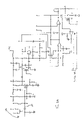
- FIGS. 3A–C are schematic diagrams of a portion of the electrical system shown in FIG. 2 ;
- FIG. 4 is a schematic diagram of the wall control including the passive infrared detector
- FIG. 5 is a perspective view of the wall control
- FIG. 6 is a front elevational view of the wall control shown in FIG. 6 ;
- FIG. 7 is a side view of the wall control shown in FIG. 6 ;
- FIG. 8 is a rear elevational view of the wall control shown in FIG. 6 ;
- FIG. 9 is a side view, shown in cross section, of the wall control in FIG. 7 ;
- FIG. 10 is a plan view, shown in cross section, of the wall control
- FIG. 11 is a partially exploded perspective view of the wall control shown in FIG. 5 ;
- FIGS. 12A–H are flow charts showing details of a program flow controlling the operation of a microcontroller contained within the wall control as shown in FIGS. 3A–C .
- a movable barrier operator embodying the present invention is shown therein and generally identified by reference numeral 10 .
- the movable barrier operator in this embodiment a garage door operator 10 , is positioned within a garage 12 . More specifically, it is mounted to a ceiling 14 of the garage 12 for operation, in this embodiment, of a multipanel garage door 16 .
- the multipanel garage door 16 includes a plurality of rollers 18 rotatably confined within a pair of tracks 20 positioned adjacent to and on opposite sides of an opening 22 for the garage door 16 .
- the garage door operator 10 also includes a head unit 24 for providing motion to the garage door 16 via a rail assembly 26 .
- the rail assembly 26 includes a trolley 28 for releasable connection of the head unit 24 to the garage door 16 via an arm 30 .
- the arm 30 is connected to an upper portion 32 of the garage door 16 for opening and closing it.
- the trolley 28 is connected to an endless chain to be driven thereby.
- the chain is driven by a sprocket in the head unit 24 .
- the sprocket acts as a power takeoff for an electric motor located in the head unit 24 .
- the head unit 24 includes a radio frequency receiver 50 , as may best be seen in FIG. 2 , having an antenna 52 associated with it for receiving coded radio frequency transmissions from one or more radio transmitters 53 which may include portable or keyfob transmitters or keypad transmitters.
- the radio receiver 50 is connected via a line 54 to a microcontroller 56 which interprets signals from the radio receiver 50 as code commands to control other portions of the garage door operator 10 .
- a wall control unit 60 embodying the present invention communicates over a line 62 with the head unit microcontroller 56 to effect control of a garage door operator motor 70 and a light 72 via relay logic 74 connected to the microcontroller 56 .
- the entire head unit 24 is powered from a power supply 76 .
- the garage door operator 10 includes an obstacle detector 78 which optically or via an infrared pulsed beam detects when the garage door opening 22 is blocked and signals the microcontroller 56 of the blockage. The microcontroller 56 then causes a reversal or opening of the door 16 .
- FIGS. 3A–C are schematic diagrams of a portion of the electrical system shown in FIG. 2 .
- the wall control 60 includes a passive infrared sensor 100 having an output line 102 connected to a differential amplifier 104 .
- the differential amplifier 104 feeds a pair of comparators 106 and 108 coupled to a wall control microcontroller 110 , in this embodiment a Microchip PIC 16505.
- the sensor 100 changing signals from the comparators when the infrared illumination changes at the passive infrared sensor 100 .
- the microcontroller 110 provides an output at line 112 to the line 62 , which is connected to the microcontroller in the GDO head.
- a momentary contact light switch 120 is connected through a capacitor 130 to other portions of the wall control 60 .
- the vacation switch 124 is connected through a capacitor 132 to the wall control 60 .
- the capacitor 132 has a different value than the capacitor 130 .
- the wall control 60 controls the microcontroller 56 through its switches by the effective pulse width or charging time required when a respective switch closes as governed by its associated capacitor or by the direct connection, as is set forth for the door control switch 122 .
- an ambient light sensor 140 is provided connected in a voltage divider circuit having a variable resistance 134 which feeds a comparator 150 which supplies an ambient light level signal over a line 152 to the microcontroller 110 .
- FIGS. 5–11 are various views of the wall control 60 discussed above.
- FIGS. 12A–H are flow charts showing details of a program flow controlling the apparatus of microcontroller 56 contained within the wall control 60 as shown in FIGS. 3A–C .
- step 500 when the processor or microcontroller 110 powers up ports and outputs are set as well as the timer in a step 500 at which point a main loop is entered and the timer is read in a step 502 .
- a test is made to determine if 10 milliseconds have elapsed in step 504 if they have not, control is transferred back to step 502 . If they have, the pulse width modulation cycle is cleared in a step 506 in order to start the pulse width modulation to govern the setpoint for the illumination.
- step 508 the pulse width modulation output is turned on and the pulse width modulation counter is cleared.
- step 510 the pulse width modulation counter is incremented and a test is made to determine whether the pulse width modulation counter is equal to the pulse width modulation value in a step 512 . If it is not, control is transferred to step 510 . If it is, control is transferred to a step 514 where the pulse width modulator has the counter cleared and is turned off and the pulse width modulation value is output.
- step 516 the pulse width modulation counter is incremented and a test is made to determine whether the value of the pulse width modulation counter is equal to pwm rem in a step 518 . If it is not, control is transferred back to step 516 .
- the pulse width modulation cycle is incremented in a step 520 , and a test is made in step 522 to determine whether it is equal to six. If it is not, control is transferred back to step 508 to restart the pulse width modulation. If it is, the pulse width modulator is turned off in step 526 and a read comparison is made in a step 530 . If the read comparator is high, the plunge counter is decremented in a step 532 , and the increment counter is incremented in a step 534 . In a step 536 , the value of the incremented counter is tested to determine whether it is greater than 10 . If it is, the counter is cleared and a step 538 . If it is not, control is transferred to a step 540 where the pulse width remainder value is set equal to pulse width modulation value compliment.
- a leap counter is cleared in a step 550 and a decrement counter is incremented in a step 552 .
- a test is made in a step 554 to determine whether the decrement counter value is greater than 10 . If it is not, control is passed to step 540 . If it is, the decrement counter is cleared in a step 556 and a test is made to determine whether the pulse width modulation value is zero in a step 560 . If it is zero, control is transferred to step 540 . If it is not, the pulse width modulation value is decremented, the plunge counter is incremented in a step 562 .
- a step 564 the plunge counter is tested to determine whether it is greater than 12 . If it is, the pulse width modulation value is tested for whether it is less than 20 in a step 566 . If it is not, the pulse width modulation value is set equal to the pulse width modulation value minus nine in a step 568 and control is transferred to the step 540 .
- a test step 570 is entered to determine whether the light on state has been set by the head unit of the movable barrier operator. If it is not, a test is made in a step 522 to determine whether the awake timer is active. If the awake timer is active, control is transferred to a step 574 causing a 16-bit counter timer to be incremented and to blank any bit counter. If the timer is not active, control is transferred to determine whether the blank timer is active in a step 576 . If it is, control is transferred to step 574 . If it is not, control is transferred to a test step 578 to determine whether checking is active.
- checking is active, the checking counter is incremented in the step 530 and a test is made to determine whether the value of the checking counter is equal to one second in a step 582 . If it is not, control is transferred to a test step 600 , as shown in FIG. 12D . If it is, a test is made to determine whether the light-on flag is on or not in a step 602 . If it is on, a test is made in a step 604 to determine whether the present pulse width modulation value is equal to the stored modulation value. If it is indicated to be lighter, control is transferred to a step 606 to clear checking.
- control is transferred to a step 608 causing the work light signal to e toggled by the wall control over the lines connected to the head unit. If the light-on value flag is indicated to be off, a test is made in a step 610 to determine whether the present pulse width modulation value is equal to the stored value. If it's indicated to be dimmer, control is transferred to the step 606 . If it's indicated to be lighter, step 612 turns on the work light toggle to flip the light state and transfers control to step 606 .
- a test is made in step 600 , as shown in FIG. 12D , to determine whether the awake flag has been set. If it has, a test is made in a step 620 to determine whether the work light toggle is active. If it is, the pulse width value is incremented in a step 622 , and a test is made to determine whether the pulse width count is equal to 20 (which is equivalent to 200 milliseconds) in a step 624 . If it is not, the work light is toggled off in a step 626 . In the event that the awake flag has not been set, a test is made in a step 630 to determine whether the RC time constant for the power supply has expired.
- step 630 has the power been kept high for more than 1.5 minutes as tested for in step 630 . If it has not, control is transferred back to the main loop in FIG. 12A . If it is, the awake value is set and the timer is cleared in the step 634 , and control is transferred back to the main loop. In the event that the time constant has expired in step 630 , the awake flag is cleared and the counts are set high in the step 636 after which control is transferred back to the main loop. After the work light has been toggled and the step 626 , a step is made in a step 660 , as may best be seen in FIG. 12E to determine if the blank timer is active. If it is, it is checked.
- a test is made to determine whether there is indicated to be activity from the passive infrared input indicating a change in a step 662 . If not, a quiet state is entered. If the PIR has been indicated to be active, a second test is made to determine whether the PIR still indicates that it is changing to indicate that a false signal has not been received. If it is, a test is made to determine whether the work light is on within the garage. If the work light is on, control is transferred back to the main loop. If the work light is indicated not to be on, a test is made to determine whether the pulse width value is greater than 128 , in other words, whether the garage is indicated to be bright or dim.
- control is transferred back to the main loop. If it's indicated to be dim, control is transferred to the test step 680 , as may best be seen in FIG. 12G to determine whether two-and-one-half seconds had elapsed. If they have not, the blank timer is turned off in the step 682 . If they have, a test is made in the step 684 to determine whether the light-on state has been set. If it has, a test is made in a step 686 to determine whether six minutes have passed. If they have, the timer is cleared, the light-on flag is cleared, the blank flag is set, and an attempt is made to read the light state from the head unit via serial communication in a step 688 .
- a test is made in a step 690 to determine whether the serial communication has been successful. If it has, a test is then made in a step 692 to determine whether the light-on flag has been returned from the head unit to the wall control. If it has, indicating the light has been set on, the toggle output is set in a step 694 . If it has not, control has been transferred to the main loop. If serial communication has failed, as tested for in step 690 , the toggle output is set in a step 700 , pulse width modulated value is stored in a step 702 , and checking is set in a step 704 prior to transfer back to the main loop.
- a step 750 there is a delay until a key reading pulse in a step 752 and a timer is reset in a step 754 .
- a 500 microsecond delay is waited for in a step 756 .
- a series of delays are used to generate an on-off output code of varying pulse widths followed by a 100 microsecond delay in a step 758 .
- a test is then made in a step 760 to determine whether the wall control input pin is low. If it is not, the test is remade. If it is, control is transferred to a step 762 to set a flag indicating serial communication is successful.
- a time value is set is a step 766 and status is read in a step 768 .
- a test is made in step 770 to determine whether the serial is okay and in a test 772 a brake signal is tested for and sent.
- a step 800 the query light is called.
- a test is made in a step 802 to determine whether it was readable by a serial communication with the head. If it was, a test is made in a step 804 to determine whether the light was on. If it was, control is transferred back to the main loop. If it was not, the toggle output is set to indicate that the state was light-on in step 806 to force the light to be on.
Abstract
Description
Claims (16)
Priority Applications (1)
| Application Number | Priority Date | Filing Date | Title |
|---|---|---|---|
| US10/717,263 US7161319B2 (en) | 1999-04-07 | 2003-11-19 | Movable barrier operator having serial data communication |
Applications Claiming Priority (3)
| Application Number | Priority Date | Filing Date | Title |
|---|---|---|---|
| US12820999P | 1999-04-07 | 1999-04-07 | |
| US09/544,904 US6737968B1 (en) | 1999-04-07 | 2000-04-07 | Movable barrier operator having passive infrared detector |
| US10/717,263 US7161319B2 (en) | 1999-04-07 | 2003-11-19 | Movable barrier operator having serial data communication |
Related Parent Applications (1)
| Application Number | Title | Priority Date | Filing Date |
|---|---|---|---|
| US09/544,904 Continuation US6737968B1 (en) | 1999-04-07 | 2000-04-07 | Movable barrier operator having passive infrared detector |
Publications (2)
| Publication Number | Publication Date |
|---|---|
| US20040155771A1 US20040155771A1 (en) | 2004-08-12 |
| US7161319B2 true US7161319B2 (en) | 2007-01-09 |
Family
ID=32302089
Family Applications (3)
| Application Number | Title | Priority Date | Filing Date |
|---|---|---|---|
| US09/544,904 Expired - Lifetime US6737968B1 (en) | 1999-04-07 | 2000-04-07 | Movable barrier operator having passive infrared detector |
| US10/717,263 Expired - Lifetime US7161319B2 (en) | 1999-04-07 | 2003-11-19 | Movable barrier operator having serial data communication |
| US10/747,428 Abandoned US20040217860A1 (en) | 1999-04-07 | 2003-12-29 | Movable barrier operator having passive infrared detector |
Family Applications Before (1)
| Application Number | Title | Priority Date | Filing Date |
|---|---|---|---|
| US09/544,904 Expired - Lifetime US6737968B1 (en) | 1999-04-07 | 2000-04-07 | Movable barrier operator having passive infrared detector |
Family Applications After (1)
| Application Number | Title | Priority Date | Filing Date |
|---|---|---|---|
| US10/747,428 Abandoned US20040217860A1 (en) | 1999-04-07 | 2003-12-29 | Movable barrier operator having passive infrared detector |
Country Status (1)
| Country | Link |
|---|---|
| US (3) | US6737968B1 (en) |
Cited By (22)
| Publication number | Priority date | Publication date | Assignee | Title |
|---|---|---|---|---|
| US20050236905A1 (en) * | 2004-04-13 | 2005-10-27 | Lincoln Tsai | Telecommunication control system |
| US20080159381A1 (en) * | 2004-08-23 | 2008-07-03 | Microchip Technology Incorporated | Apparatus and Method for Generating Push-Pull Pulse Width Modulation Signals |
| US20090284386A1 (en) * | 2008-05-13 | 2009-11-19 | Shary Nassimi | Method and Apparatus to Facilitate Automated Control of Local Lighting at a Remote Control |
| US20110084798A1 (en) * | 2005-01-27 | 2011-04-14 | The Chamberlain Group, Inc. | System Interaction with a Movable Barrier Operator Method and Apparatus |
| US8976006B2 (en) | 2011-05-24 | 2015-03-10 | Overhead Door Corporation | Wall console diverse commands to barrier operators |
| US8994496B2 (en) | 2011-04-01 | 2015-03-31 | The Chamberlain Group, Inc. | Encrypted communications for a moveable barrier environment |
| US9122254B2 (en) | 2012-11-08 | 2015-09-01 | The Chamberlain Group, Inc. | Barrier operator feature enhancement |
| US9367978B2 (en) | 2013-03-15 | 2016-06-14 | The Chamberlain Group, Inc. | Control device access method and apparatus |
| US9396598B2 (en) | 2014-10-28 | 2016-07-19 | The Chamberlain Group, Inc. | Remote guest access to a secured premises |
| US9449449B2 (en) | 2013-03-15 | 2016-09-20 | The Chamberlain Group, Inc. | Access control operator diagnostic control |
| US9698997B2 (en) | 2011-12-13 | 2017-07-04 | The Chamberlain Group, Inc. | Apparatus and method pertaining to the communication of information regarding appliances that utilize differing communications protocol |
| US9909351B1 (en) | 2017-03-17 | 2018-03-06 | Tti (Macao Commercial Offshore) Limited | Garage door opener system and method of operating a garage door opener system |
| US9970228B2 (en) * | 2013-10-04 | 2018-05-15 | The Chamberlain Group, Inc. | Movable barrier safety sensor override |
| US9978265B2 (en) | 2016-04-11 | 2018-05-22 | Tti (Macao Commercial Offshore) Limited | Modular garage door opener |
| US10015898B2 (en) | 2016-04-11 | 2018-07-03 | Tti (Macao Commercial Offshore) Limited | Modular garage door opener |
| US10096187B2 (en) | 2015-04-09 | 2018-10-09 | Overhead Door Corporation | Automatic transmission of a barrier status and change of status over a network |
| US10229548B2 (en) | 2013-03-15 | 2019-03-12 | The Chamberlain Group, Inc. | Remote guest access to a secured premises |
| US10253545B2 (en) | 2017-01-20 | 2019-04-09 | Adh Guardian Usa, Llc | Backup power unit for powered barrier operators |
| US10619397B2 (en) * | 2015-09-14 | 2020-04-14 | Rytec Corporation | System and method for safety management in roll-up doors |
| US11308019B2 (en) | 2019-05-30 | 2022-04-19 | D. H. Pace Company, Inc. | Systems and methods for door and dock equipment servicing |
| US11346141B2 (en) | 2018-12-21 | 2022-05-31 | Rytec Corporation | Safety system and method for overhead roll-up doors |
| US11812533B2 (en) | 2021-06-08 | 2023-11-07 | Gmi Holdings, Inc. | Synchronized lighting with toggle system |
Families Citing this family (25)
| Publication number | Priority date | Publication date | Assignee | Title |
|---|---|---|---|---|
| US7057519B2 (en) * | 2002-04-30 | 2006-06-06 | The Chamberlain Group, Inc. | Automatic sensing of safe-operation sensor apparatus and method |
| US6982652B2 (en) * | 2002-05-14 | 2006-01-03 | The Chamberlain Group, Inc. | Movable barrier operator with multiple lighting schemes and method |
| US7755223B2 (en) * | 2002-08-23 | 2010-07-13 | The Chamberlain Group, Inc. | Movable barrier operator with energy management control and corresponding method |
| DE202005000270U1 (en) * | 2005-01-10 | 2006-05-24 | Marantec Antriebs- Und Steuerungstechnik Gmbh & Co. Kg | Photocells holder |
| US7208897B2 (en) * | 2005-03-04 | 2007-04-24 | Linear Corporation | Motion control system for barrier drive |
| US7038409B1 (en) * | 2005-03-16 | 2006-05-02 | Wayne-Dalton Corp. | Operating system utilizing a delay-open function for a motorized barrier operator |
| US7382063B2 (en) * | 2005-05-24 | 2008-06-03 | Wayne-Dalton Corp. | Uninterruptible power source for a barrier operator and related methods |
| US20070174075A1 (en) * | 2006-01-25 | 2007-07-26 | International Business Machines Corporation | Tamper sensitive warranty management for autonomic computing systems |
| US20080195413A1 (en) * | 2006-01-25 | 2008-08-14 | Jeffrey Franke | Design structure for tamper sensitive warranty management for autonomic computing systems |
| US7265508B1 (en) | 2006-03-31 | 2007-09-04 | The Chamberlain Group, Inc. | Movable light for use with a movable barrier operator |
| US8014966B2 (en) | 2006-06-23 | 2011-09-06 | Overhead Door Corporation | Calibration and setup unit for barrier operator control system |
| ITTV20070013A1 (en) * | 2007-02-05 | 2008-08-06 | Nice Spa | BUS SYSTEM AND RELATIVE TRANSMISSION PROTOCOL |
| US20110173890A1 (en) * | 2010-01-20 | 2011-07-21 | Gantner Mark A | Garage Door Sensor Protector |
| US8387309B2 (en) * | 2010-07-09 | 2013-03-05 | Li-Yu Tseng | Automatic waterproof gate |
| US8769878B1 (en) * | 2010-08-06 | 2014-07-08 | Miller Edge, Inc. | Photo eye to switch sensing edge control conversion system |
| US8495834B2 (en) * | 2011-01-07 | 2013-07-30 | Linear Llc | Obstruction detector power control |
| US8665065B2 (en) | 2011-04-06 | 2014-03-04 | The Chamberlain Group, Inc. | Barrier operator with power management features |
| TW201445043A (en) | 2013-05-24 | 2014-12-01 | Zeng li yu | Inductive fully automatic power flood control rolling gate and automatic positioning reinforced post thereof |
| US9303448B2 (en) * | 2013-10-23 | 2016-04-05 | Zachary Dax Olkin | Flood shield systems and methods |
| US9778114B2 (en) | 2015-08-26 | 2017-10-03 | Google Inc. | Integrated antenna system and related component management |
| US10854028B2 (en) * | 2016-08-09 | 2020-12-01 | Vivint, Inc. | Authentication for keyless building entry |
| US11028633B2 (en) | 2018-12-06 | 2021-06-08 | The Chamberlain Group, Inc. | Automatic control of a movable barrier |
| US11578527B2 (en) | 2019-07-08 | 2023-02-14 | The Chamberlain Group Llc | In-vehicle device for controlling a movable barrier operator |
| US11600126B2 (en) * | 2020-05-08 | 2023-03-07 | The Chamberlain Group Llc | Movable barrier operator system and methods of installation and use |
| DE102022122154A1 (en) | 2022-09-01 | 2024-03-07 | Novoferm Tormatic Gmbh | Goal |
Citations (33)
| Publication number | Priority date | Publication date | Assignee | Title |
|---|---|---|---|---|
| US4549092A (en) | 1981-03-10 | 1985-10-22 | Hitachi, Ltd. | Control system for illumination lamp installed in building equipped with door operation control apparatus |
| US4638433A (en) * | 1984-05-30 | 1987-01-20 | Chamberlain Manufacturing Corporation | Microprocessor controlled garage door operator |
| US4771218A (en) | 1984-03-08 | 1988-09-13 | Mcgee Michael H | Electrically actuated overhead garage door opener with solenoid actuated latches |
| US4808995A (en) | 1986-05-02 | 1989-02-28 | Stanley Automatic Openers | Accessory-expandable, radio-controlled, door operator with multiple security levels |
| US4988992A (en) * | 1989-07-27 | 1991-01-29 | The Chamberlain Group, Inc. | System for establishing a code and controlling operation of equipment |
| US5282337A (en) * | 1993-02-22 | 1994-02-01 | Stanley Home Automation | Garage door operator with pedestrian light control |
| US5285136A (en) | 1991-08-26 | 1994-02-08 | Stanley Home Automation | Continuously monitored supplemental obstruction detector for garage door operator |
| US5357183A (en) | 1992-02-07 | 1994-10-18 | Lin Chii C | Automatic control and safety device for garage door opener |
| US5475374A (en) * | 1994-01-31 | 1995-12-12 | Motorola, Inc. | Method and apparatus for energy conservation in a communication system |
| US5589747A (en) | 1995-07-06 | 1996-12-31 | Utke; Michael C. | Light and motion governed garage door opener lamp |
| US5625980A (en) | 1993-09-15 | 1997-05-06 | Rmt Associates | Garage door opener with remote safety sensors |
| US5656900A (en) | 1995-06-05 | 1997-08-12 | The Chamberlain Group, Inc. | Retro-reflective infrared safety sensor for garage door operators |
| US5684372A (en) | 1991-04-09 | 1997-11-04 | The Chamberlain Group, Inc. | Garage door operator safety apparatus |
| US5751224A (en) * | 1995-05-17 | 1998-05-12 | The Chamberlain Group, Inc. | Code learning system for a movable barrier operator |
| US5752343A (en) | 1996-04-29 | 1998-05-19 | Quintus; James B. | Universal garage door closer |
| US5780987A (en) * | 1995-05-17 | 1998-07-14 | The Chamberlain Group, Inc. | Barrier operator having system for detecting attempted forced entry |
| US5872513A (en) | 1996-04-24 | 1999-02-16 | The Chamberlain Group, Inc. | Garage door opener and wireless keypad transmitter with temporary password feature |
| US5929580A (en) | 1997-08-05 | 1999-07-27 | Wayne-Dalton Corp. | System and related methods for detecting an obstruction in the path of a garage door controlled by an open-loop operator |
| US5933091A (en) | 1996-08-12 | 1999-08-03 | Mccaslin; Robert E. | Remotely-actuated infrared-sensitive switch |
| US5950364A (en) | 1995-10-31 | 1999-09-14 | Marantec Antriebs-Und Steurungstechnik Gmbh & Co. Produktions Kg | Monitoring the motion of a drive-operable, one or multiple part door body |
| US5969637A (en) | 1996-04-24 | 1999-10-19 | The Chamberlain Group, Inc. | Garage door opener with light control |
| US6049289A (en) * | 1996-09-06 | 2000-04-11 | Overhead Door Corporation | Remote controlled garage door opening system |
| US6107765A (en) * | 1995-06-06 | 2000-08-22 | The Chamberlain Group, Inc. | Movable barrier operator having force and position learning capability |
| US6172475B1 (en) * | 1998-09-28 | 2001-01-09 | The Chamberlain Group, Inc. | Movable barrier operator |
| US6181095B1 (en) | 1997-06-30 | 2001-01-30 | Kds Controls, Inc. | Garage door opener |
| US6326754B1 (en) | 2000-01-28 | 2001-12-04 | Wayne-Dalton Corp. | Wireless operating system utilizing a multi-functional wall station transmitter for a motorized door or gate operator |
| US6388559B1 (en) | 1998-12-22 | 2002-05-14 | Lucent Technologies, Inc. | Remote control device and a method of using the same |
| US6624605B1 (en) | 2001-06-06 | 2003-09-23 | Telephonics Corporation | Method, system and apparatus for opening doors |
| US6710564B2 (en) * | 2001-08-29 | 2004-03-23 | Sanden Corporation | Methods and apparatus for controlling brushless motors |
| US6757583B2 (en) * | 2002-06-27 | 2004-06-29 | Joe Giamona | Interpolated motion control over a serial network |
| US6864646B2 (en) * | 2003-02-14 | 2005-03-08 | General Motors Corporation | Multiple inverter system with low power bus ripples and method therefor |
| US6919702B2 (en) * | 2003-01-16 | 2005-07-19 | Mpc Products Corporation | Systems and methods for passivation of servo motors |
| US7002312B2 (en) * | 2003-12-30 | 2006-02-21 | The Chamberlain Group, Inc. | System and method of actuating a movable barrier operator |
Family Cites Families (2)
| Publication number | Priority date | Publication date | Assignee | Title |
|---|---|---|---|---|
| US37784A (en) * | 1863-02-24 | Island | ||
| US6346889B1 (en) * | 2000-07-01 | 2002-02-12 | Richard D. Moss | Security system for automatic door |
-
2000
- 2000-04-07 US US09/544,904 patent/US6737968B1/en not_active Expired - Lifetime
-
2003
- 2003-11-19 US US10/717,263 patent/US7161319B2/en not_active Expired - Lifetime
- 2003-12-29 US US10/747,428 patent/US20040217860A1/en not_active Abandoned
Patent Citations (35)
| Publication number | Priority date | Publication date | Assignee | Title |
|---|---|---|---|---|
| US4549092A (en) | 1981-03-10 | 1985-10-22 | Hitachi, Ltd. | Control system for illumination lamp installed in building equipped with door operation control apparatus |
| US4771218A (en) | 1984-03-08 | 1988-09-13 | Mcgee Michael H | Electrically actuated overhead garage door opener with solenoid actuated latches |
| US4638433A (en) * | 1984-05-30 | 1987-01-20 | Chamberlain Manufacturing Corporation | Microprocessor controlled garage door operator |
| US4808995A (en) | 1986-05-02 | 1989-02-28 | Stanley Automatic Openers | Accessory-expandable, radio-controlled, door operator with multiple security levels |
| US4988992A (en) * | 1989-07-27 | 1991-01-29 | The Chamberlain Group, Inc. | System for establishing a code and controlling operation of equipment |
| US5684372A (en) | 1991-04-09 | 1997-11-04 | The Chamberlain Group, Inc. | Garage door operator safety apparatus |
| US5285136A (en) | 1991-08-26 | 1994-02-08 | Stanley Home Automation | Continuously monitored supplemental obstruction detector for garage door operator |
| US5357183A (en) | 1992-02-07 | 1994-10-18 | Lin Chii C | Automatic control and safety device for garage door opener |
| US5282337A (en) * | 1993-02-22 | 1994-02-01 | Stanley Home Automation | Garage door operator with pedestrian light control |
| US5625980A (en) | 1993-09-15 | 1997-05-06 | Rmt Associates | Garage door opener with remote safety sensors |
| US5475374A (en) * | 1994-01-31 | 1995-12-12 | Motorola, Inc. | Method and apparatus for energy conservation in a communication system |
| US5751224A (en) * | 1995-05-17 | 1998-05-12 | The Chamberlain Group, Inc. | Code learning system for a movable barrier operator |
| USRE37784E1 (en) | 1995-05-17 | 2002-07-09 | The Chamberlain Group, Inc. | Barrier operator having system for detecting attempted forced entry |
| US5780987A (en) * | 1995-05-17 | 1998-07-14 | The Chamberlain Group, Inc. | Barrier operator having system for detecting attempted forced entry |
| US5656900A (en) | 1995-06-05 | 1997-08-12 | The Chamberlain Group, Inc. | Retro-reflective infrared safety sensor for garage door operators |
| US6111374A (en) * | 1995-06-06 | 2000-08-29 | The Chamberlain Group, Inc. | Movable barrier operator having force and position learning capability |
| US6107765A (en) * | 1995-06-06 | 2000-08-22 | The Chamberlain Group, Inc. | Movable barrier operator having force and position learning capability |
| US5589747A (en) | 1995-07-06 | 1996-12-31 | Utke; Michael C. | Light and motion governed garage door opener lamp |
| US5950364A (en) | 1995-10-31 | 1999-09-14 | Marantec Antriebs-Und Steurungstechnik Gmbh & Co. Produktions Kg | Monitoring the motion of a drive-operable, one or multiple part door body |
| US5872513A (en) | 1996-04-24 | 1999-02-16 | The Chamberlain Group, Inc. | Garage door opener and wireless keypad transmitter with temporary password feature |
| US5969637A (en) | 1996-04-24 | 1999-10-19 | The Chamberlain Group, Inc. | Garage door opener with light control |
| US5752343A (en) | 1996-04-29 | 1998-05-19 | Quintus; James B. | Universal garage door closer |
| US5933091A (en) | 1996-08-12 | 1999-08-03 | Mccaslin; Robert E. | Remotely-actuated infrared-sensitive switch |
| US6049289A (en) * | 1996-09-06 | 2000-04-11 | Overhead Door Corporation | Remote controlled garage door opening system |
| US6181095B1 (en) | 1997-06-30 | 2001-01-30 | Kds Controls, Inc. | Garage door opener |
| US5929580A (en) | 1997-08-05 | 1999-07-27 | Wayne-Dalton Corp. | System and related methods for detecting an obstruction in the path of a garage door controlled by an open-loop operator |
| US6172475B1 (en) * | 1998-09-28 | 2001-01-09 | The Chamberlain Group, Inc. | Movable barrier operator |
| US6388559B1 (en) | 1998-12-22 | 2002-05-14 | Lucent Technologies, Inc. | Remote control device and a method of using the same |
| US6326754B1 (en) | 2000-01-28 | 2001-12-04 | Wayne-Dalton Corp. | Wireless operating system utilizing a multi-functional wall station transmitter for a motorized door or gate operator |
| US6624605B1 (en) | 2001-06-06 | 2003-09-23 | Telephonics Corporation | Method, system and apparatus for opening doors |
| US6710564B2 (en) * | 2001-08-29 | 2004-03-23 | Sanden Corporation | Methods and apparatus for controlling brushless motors |
| US6757583B2 (en) * | 2002-06-27 | 2004-06-29 | Joe Giamona | Interpolated motion control over a serial network |
| US6919702B2 (en) * | 2003-01-16 | 2005-07-19 | Mpc Products Corporation | Systems and methods for passivation of servo motors |
| US6864646B2 (en) * | 2003-02-14 | 2005-03-08 | General Motors Corporation | Multiple inverter system with low power bus ripples and method therefor |
| US7002312B2 (en) * | 2003-12-30 | 2006-02-21 | The Chamberlain Group, Inc. | System and method of actuating a movable barrier operator |
Non-Patent Citations (1)
| Title |
|---|
| International Search Report for PCT/US00/09330 issued by the European Patent Office on Apr. 7, 2000. |
Cited By (51)
| Publication number | Priority date | Publication date | Assignee | Title |
|---|---|---|---|---|
| US20050236905A1 (en) * | 2004-04-13 | 2005-10-27 | Lincoln Tsai | Telecommunication control system |
| US20080159381A1 (en) * | 2004-08-23 | 2008-07-03 | Microchip Technology Incorporated | Apparatus and Method for Generating Push-Pull Pulse Width Modulation Signals |
| US20080159382A1 (en) * | 2004-08-23 | 2008-07-03 | Bryan Kris | Apparatus and Method for Generating Current Reset Mode Pulse Width Modulation Signals |
| US7502436B2 (en) * | 2004-08-23 | 2009-03-10 | Microchip Technology Incorporated | Apparatus and method for generating push-pull pulse width modulation signals |
| US7508901B2 (en) * | 2004-08-23 | 2009-03-24 | Microchip Technology Incorporated | Apparatus and method for generating current reset mode pulse width modulation signals |
| US7508900B2 (en) * | 2004-08-23 | 2009-03-24 | Microchip Technology Incorporated | Apparatus for improved resolution pulse width modulation module duty cycle, dead time and phase |
| US7508899B2 (en) * | 2004-08-23 | 2009-03-24 | Microchip Technology Incorporated | Apparatus and method for generating multi-phase pulse width modulation (PWM) and sharing a common (master) duty cycle value among a plurality of PWM generators |
| US7593500B2 (en) * | 2004-08-23 | 2009-09-22 | Microchip Technology Incorporated | Apparatus for coordinating triggering of analog-to-digital conversions relative to pulse width modulation cycle timing |
| US9495815B2 (en) | 2005-01-27 | 2016-11-15 | The Chamberlain Group, Inc. | System interaction with a movable barrier operator method and apparatus |
| US20110084798A1 (en) * | 2005-01-27 | 2011-04-14 | The Chamberlain Group, Inc. | System Interaction with a Movable Barrier Operator Method and Apparatus |
| US9818243B2 (en) | 2005-01-27 | 2017-11-14 | The Chamberlain Group, Inc. | System interaction with a movable barrier operator method and apparatus |
| US20090284386A1 (en) * | 2008-05-13 | 2009-11-19 | Shary Nassimi | Method and Apparatus to Facilitate Automated Control of Local Lighting at a Remote Control |
| US8325040B2 (en) * | 2008-05-13 | 2012-12-04 | The Chamberlain Group, Inc. | Method and apparatus to facilitate automated control of local lighting at a remote control |
| US8994496B2 (en) | 2011-04-01 | 2015-03-31 | The Chamberlain Group, Inc. | Encrypted communications for a moveable barrier environment |
| US9728020B2 (en) | 2011-04-01 | 2017-08-08 | The Chamberlain Group, Inc. | Encrypted communications for a movable barrier environment |
| US8976006B2 (en) | 2011-05-24 | 2015-03-10 | Overhead Door Corporation | Wall console diverse commands to barrier operators |
| US9698997B2 (en) | 2011-12-13 | 2017-07-04 | The Chamberlain Group, Inc. | Apparatus and method pertaining to the communication of information regarding appliances that utilize differing communications protocol |
| US9896877B2 (en) | 2012-11-08 | 2018-02-20 | The Chamberlain Group, Inc. | Barrier operator feature enhancement |
| US9122254B2 (en) | 2012-11-08 | 2015-09-01 | The Chamberlain Group, Inc. | Barrier operator feature enhancement |
| US11187026B2 (en) | 2012-11-08 | 2021-11-30 | The Chamberlain Group Llc | Barrier operator feature enhancement |
| US9644416B2 (en) | 2012-11-08 | 2017-05-09 | The Chamberlain Group, Inc. | Barrier operator feature enhancement |
| US9376851B2 (en) | 2012-11-08 | 2016-06-28 | The Chamberlain Group, Inc. | Barrier operator feature enhancement |
| US10597928B2 (en) | 2012-11-08 | 2020-03-24 | The Chamberlain Group, Inc. | Barrier operator feature enhancement |
| US9141099B2 (en) | 2012-11-08 | 2015-09-22 | The Chamberlain Group, Inc. | Barrier operator feature enhancement |
| US10138671B2 (en) | 2012-11-08 | 2018-11-27 | The Chamberlain Group, Inc. | Barrier operator feature enhancement |
| US10801247B2 (en) | 2012-11-08 | 2020-10-13 | The Chamberlain Group, Inc. | Barrier operator feature enhancement |
| US9449449B2 (en) | 2013-03-15 | 2016-09-20 | The Chamberlain Group, Inc. | Access control operator diagnostic control |
| US9367978B2 (en) | 2013-03-15 | 2016-06-14 | The Chamberlain Group, Inc. | Control device access method and apparatus |
| US10229548B2 (en) | 2013-03-15 | 2019-03-12 | The Chamberlain Group, Inc. | Remote guest access to a secured premises |
| US9970228B2 (en) * | 2013-10-04 | 2018-05-15 | The Chamberlain Group, Inc. | Movable barrier safety sensor override |
| US10927583B2 (en) | 2013-10-04 | 2021-02-23 | The Chamberlain Group, Inc. | Movable barrier operator apparatus with safety system override, and method |
| US10810817B2 (en) | 2014-10-28 | 2020-10-20 | The Chamberlain Group, Inc. | Remote guest access to a secured premises |
| US9396598B2 (en) | 2014-10-28 | 2016-07-19 | The Chamberlain Group, Inc. | Remote guest access to a secured premises |
| US10096187B2 (en) | 2015-04-09 | 2018-10-09 | Overhead Door Corporation | Automatic transmission of a barrier status and change of status over a network |
| US10614647B2 (en) | 2015-04-09 | 2020-04-07 | Overhead Door Corporation | Remote transmission of barrier status and change of status over a network |
| US10619397B2 (en) * | 2015-09-14 | 2020-04-14 | Rytec Corporation | System and method for safety management in roll-up doors |
| US11236540B2 (en) * | 2015-09-14 | 2022-02-01 | Rytec Corporation | System and method for safety management in roll-up doors |
| US9978265B2 (en) | 2016-04-11 | 2018-05-22 | Tti (Macao Commercial Offshore) Limited | Modular garage door opener |
| US10157538B2 (en) | 2016-04-11 | 2018-12-18 | Tti (Macao Commercial Offshore) Limited | Modular garage door opener |
| US10237996B2 (en) | 2016-04-11 | 2019-03-19 | Tti (Macao Commercial Offshore) Limited | Modular garage door opener |
| US10127806B2 (en) | 2016-04-11 | 2018-11-13 | Tti (Macao Commercial Offshore) Limited | Methods and systems for controlling a garage door opener accessory |
| US10015898B2 (en) | 2016-04-11 | 2018-07-03 | Tti (Macao Commercial Offshore) Limited | Modular garage door opener |
| US10253545B2 (en) | 2017-01-20 | 2019-04-09 | Adh Guardian Usa, Llc | Backup power unit for powered barrier operators |
| US10202793B2 (en) | 2017-03-17 | 2019-02-12 | Tti (Macao Commercial Offshore) Limited | Garage door opener system and method of operating a garage door opener system |
| US9909351B1 (en) | 2017-03-17 | 2018-03-06 | Tti (Macao Commercial Offshore) Limited | Garage door opener system and method of operating a garage door opener system |
| US10053906B1 (en) | 2017-03-17 | 2018-08-21 | Tti (Macao Commercial Offshore) Limited | Garage door opener system and method of operating a garage door opener system |
| US11346141B2 (en) | 2018-12-21 | 2022-05-31 | Rytec Corporation | Safety system and method for overhead roll-up doors |
| US11804114B2 (en) | 2018-12-21 | 2023-10-31 | Rytec Corporation | Safety system and method for overhead roll-up doors |
| US11308019B2 (en) | 2019-05-30 | 2022-04-19 | D. H. Pace Company, Inc. | Systems and methods for door and dock equipment servicing |
| US11812533B2 (en) | 2021-06-08 | 2023-11-07 | Gmi Holdings, Inc. | Synchronized lighting with toggle system |
| US11849520B2 (en) | 2021-06-08 | 2023-12-19 | Gmi Holdings, Inc. | Synchronized lighting with toggle system |
Also Published As
| Publication number | Publication date |
|---|---|
| US20040155771A1 (en) | 2004-08-12 |
| US20040217860A1 (en) | 2004-11-04 |
| US6737968B1 (en) | 2004-05-18 |
Similar Documents
| Publication | Publication Date | Title |
|---|---|---|
| US7161319B2 (en) | Movable barrier operator having serial data communication | |
| US5247232A (en) | Automatic garage door control device | |
| US5357183A (en) | Automatic control and safety device for garage door opener | |
| US5191268A (en) | Continuously monitored supplemental obstruction detector for garage door operator | |
| CA2091843C (en) | Light beam detector for door operators using fiber optics | |
| US7600550B2 (en) | Automatic barrier operator system | |
| US6563278B2 (en) | Automated garage door closer | |
| US5023597A (en) | Detection apparatus for safety eyewear | |
| USRE44816E1 (en) | Barrier movement operator including time to close feature | |
| EP0707682B1 (en) | Electrical link and sensor system for automatic sliding doors | |
| US4967083A (en) | Door sensor system | |
| US20030067394A1 (en) | Garage door monitoring system | |
| US5656900A (en) | Retro-reflective infrared safety sensor for garage door operators | |
| US20130042530A1 (en) | Beam Protection System for a Door Operator | |
| CA2680903A1 (en) | System and method for control of multiple barrier operators | |
| EP1181429B1 (en) | Movable barrier operator having passive infrared detector | |
| EP1279186A1 (en) | Multifaceted sensor system | |
| MXPA02007362A (en) | Safety interlock for mechanically actuated closure device. | |
| GB2176374A (en) | Vehicle identification system | |
| JPH07279507A (en) | Control system for access door | |
| JPH089934B2 (en) | Automatic gate opening device for construction sites and its automatic opening method |
Legal Events
| Date | Code | Title | Description |
|---|---|---|---|
| STCF | Information on status: patent grant |
Free format text: PATENTED CASE |
|
| FPAY | Fee payment |
Year of fee payment: 4 |
|
| FPAY | Fee payment |
Year of fee payment: 8 |
|
| AS | Assignment |
Owner name: THE CHAMBERLAIN GROUP, INC., ILLINOIS Free format text: ASSIGNMENT OF ASSIGNORS INTEREST;ASSIGNOR:FITZGIBBON, JAMES J.;REEL/FRAME:038804/0184 Effective date: 20060603 |
|
| IPR | Aia trial proceeding filed before the patent and appeal board: inter partes review |
Free format text: TRIAL NO: IPR2017-00126 Opponent name: ONE WORLD TECHNOLOGIES, INC. D/B/A TECHTRONIC INDU Effective date: 20161025 |
|
| MAFP | Maintenance fee payment |
Free format text: PAYMENT OF MAINTENANCE FEE, 12TH YEAR, LARGE ENTITY (ORIGINAL EVENT CODE: M1553) Year of fee payment: 12 |
|
| STCV | Information on status: appeal procedure |
Free format text: APPLICATION INVOLVED IN COURT PROCEEDINGS |
|
| AS | Assignment |
Owner name: ARES CAPITAL CORPORATION, AS COLLATERAL AGENT, NEW YORK Free format text: SECOND LIEN PATENT SECURITY AGREEMENT;ASSIGNORS:THE CHAMBERLAIN GROUP LLC;SYSTEMS, LLC;REEL/FRAME:058015/0001 Effective date: 20211103 Owner name: WELLS FARGO BANK, NATIONAL ASSOCIATION, AS COLLATERAL AGENT, COLORADO Free format text: FIRST LIEN PATENT SECURITY AGREEMENT;ASSIGNORS:THE CHAMBERLAIN GROUP LLC;SYSTEMS, LLC;REEL/FRAME:058014/0931 Effective date: 20211103 |
|
| AS | Assignment |
Owner name: SYSTEMS, LLC, ILLINOIS Free format text: NOTICE OF TERMINATION AND RELEASE OF SECURITY INTEREST IN PATENTS;ASSIGNOR:ARES CAPITAL CORPORATION, AS COLLATERAL AGENT;REEL/FRAME:066374/0749 Effective date: 20240126 Owner name: THE CHAMBERLAIN GROUP LLC, ILLINOIS Free format text: NOTICE OF TERMINATION AND RELEASE OF SECURITY INTEREST IN PATENTS;ASSIGNOR:ARES CAPITAL CORPORATION, AS COLLATERAL AGENT;REEL/FRAME:066374/0749 Effective date: 20240126 |