US7165974B2 - Multiple-position push-on electrical connector - Google Patents
Multiple-position push-on electrical connector Download PDFInfo
- Publication number
- US7165974B2 US7165974B2 US10/967,046 US96704604A US7165974B2 US 7165974 B2 US7165974 B2 US 7165974B2 US 96704604 A US96704604 A US 96704604A US 7165974 B2 US7165974 B2 US 7165974B2
- Authority
- US
- United States
- Prior art keywords
- cable
- male
- port
- connector
- coaxial cable
- Prior art date
- Legal status (The legal status is an assumption and is not a legal conclusion. Google has not performed a legal analysis and makes no representation as to the accuracy of the status listed.)
- Active
Links
Images


Classifications
-
- H—ELECTRICITY
- H01—ELECTRIC ELEMENTS
- H01R—ELECTRICALLY-CONDUCTIVE CONNECTIONS; STRUCTURAL ASSOCIATIONS OF A PLURALITY OF MUTUALLY-INSULATED ELECTRICAL CONNECTING ELEMENTS; COUPLING DEVICES; CURRENT COLLECTORS
- H01R24/00—Two-part coupling devices, or either of their cooperating parts, characterised by their overall structure
- H01R24/38—Two-part coupling devices, or either of their cooperating parts, characterised by their overall structure having concentrically or coaxially arranged contacts
- H01R24/40—Two-part coupling devices, or either of their cooperating parts, characterised by their overall structure having concentrically or coaxially arranged contacts specially adapted for high frequency
- H01R24/52—Two-part coupling devices, or either of their cooperating parts, characterised by their overall structure having concentrically or coaxially arranged contacts specially adapted for high frequency mounted in or to a panel or structure
-
- H—ELECTRICITY
- H01—ELECTRIC ELEMENTS
- H01R—ELECTRICALLY-CONDUCTIVE CONNECTIONS; STRUCTURAL ASSOCIATIONS OF A PLURALITY OF MUTUALLY-INSULATED ELECTRICAL CONNECTING ELEMENTS; COUPLING DEVICES; CURRENT COLLECTORS
- H01R2103/00—Two poles
-
- H—ELECTRICITY
- H01—ELECTRIC ELEMENTS
- H01R—ELECTRICALLY-CONDUCTIVE CONNECTIONS; STRUCTURAL ASSOCIATIONS OF A PLURALITY OF MUTUALLY-INSULATED ELECTRICAL CONNECTING ELEMENTS; COUPLING DEVICES; CURRENT COLLECTORS
- H01R24/00—Two-part coupling devices, or either of their cooperating parts, characterised by their overall structure
- H01R24/38—Two-part coupling devices, or either of their cooperating parts, characterised by their overall structure having concentrically or coaxially arranged contacts
- H01R24/40—Two-part coupling devices, or either of their cooperating parts, characterised by their overall structure having concentrically or coaxially arranged contacts specially adapted for high frequency
- H01R24/54—Intermediate parts, e.g. adapters, splitters or elbows
- H01R24/545—Elbows
-
- H—ELECTRICITY
- H01—ELECTRIC ELEMENTS
- H01R—ELECTRICALLY-CONDUCTIVE CONNECTIONS; STRUCTURAL ASSOCIATIONS OF A PLURALITY OF MUTUALLY-INSULATED ELECTRICAL CONNECTING ELEMENTS; COUPLING DEVICES; CURRENT COLLECTORS
- H01R43/00—Apparatus or processes specially adapted for manufacturing, assembling, maintaining, or repairing of line connectors or current collectors or for joining electric conductors
- H01R43/26—Apparatus or processes specially adapted for manufacturing, assembling, maintaining, or repairing of line connectors or current collectors or for joining electric conductors for engaging or disengaging the two parts of a coupling device
-
- H—ELECTRICITY
- H01—ELECTRIC ELEMENTS
- H01R—ELECTRICALLY-CONDUCTIVE CONNECTIONS; STRUCTURAL ASSOCIATIONS OF A PLURALITY OF MUTUALLY-INSULATED ELECTRICAL CONNECTING ELEMENTS; COUPLING DEVICES; CURRENT COLLECTORS
- H01R9/00—Structural associations of a plurality of mutually-insulated electrical connecting elements, e.g. terminal strips or terminal blocks; Terminals or binding posts mounted upon a base or in a case; Bases therefor
- H01R9/03—Connectors arranged to contact a plurality of the conductors of a multiconductor cable, e.g. tapping connections
- H01R9/05—Connectors arranged to contact a plurality of the conductors of a multiconductor cable, e.g. tapping connections for coaxial cables
- H01R9/0521—Connection to outer conductor by action of a nut
Definitions
- This invention relates to electrical connectors, and more particularly to an electrical connector system having a plurality of push-on style interfaces and designed to connect a plurality of coaxial cables to a printed wiring board.
- Microwave connectors having a push-on style interface such as a subminiature push-on (“SMP”) interface and a SMP-miniature (“SMPM”) interface, as described in MIL-STD-348A, are well known.
- Microwave connectors having a port with a push-on style interface designed to connect a coaxial cable to a printed wiring board (“PWB”) are well known.
- PWB printed wiring board
- all such known microwave connectors having a push-on style interface are single-position connectors.
- a plurality of coaxial cables are coupled to a PWB, a plurality of single-position connectors is needed.
- the plurality of coaxial cables cannot be uncoupled from the plurality of single-position connectors with a single action.
- known single-position microwave connectors having a push-on style interface have a cable adapter that is press-fit into the connector body, thereby disadvantageously being thermally integral with the connector body, which can slow the process of soldering a coaxial cable to the cable adapter.
- Some multiple-position coaxial cable connectors have a provision for the individual coaxial cable and connector assemblies to be field replaceable.
- Such known multiple-position coaxial cables connectors have a spring-action snap ring, a plastic insert, and a lip on the connector.
- Such known multiple-position coaxial cables connectors are disadvantageously relatively large—usually about two inches in diameter.
- Multiple-position connectors designed to connect a coaxial cable to a PWB are also well known. However, all known multiple-position connectors designed to connect a coaxial cable to a PWB lack any provision to allow the coaxial cables to be individually field replaceable.
- FIG. 1 is a perspective view of an eight-position, right-angle, coaxial cable-to-male, push-on connector including a cable adapter and a clamp nut at several of the cable ports, and including an exploded view at one of the cable ports;
- FIG. 2 is another perspective view of the eight-position, right-angle, coaxial cable-to-male, push-on connector of FIG. 1 , showing the male ports;
- FIG. 3 is a cross-sectional view through cut-line 3 — 3 of FIG. 1 ;
- FIG. 4 is a perspective view of the eight-position, right-angle, coaxial cable-to-male, push-on connector of FIG. 1 , including a coaxial cable connected to each cable port of the connector;
- FIG. 5 is a cross-sectional view through cut-line 5 — 5 of FIG. 4 ;
- FIG. 6 is an enlarged perspective view of the clamp nut shown in FIG. 1 ;
- FIG. 7 is an enlarged perspective view of the cable adapter shown in FIG. 1 ;
- FIG. 8 is a perspective view of a typical known female-to-female bullet that is used to couple the male ports of two connectors;
- FIG. 9 is a perspective view of the eight-position, right-angle, coaxial cable-to-male, push-on connector of FIG. 2 , including the female-to-female bullet of FIG. 8 attached to each male port of the connector;
- FIG. 10 is a perspective view of an eight-position, right-angle, push-on, male-to-PWB connector
- FIG. 11 is another perspective view of the eight-position, right-angle, push-on, male-to-PWB connector of FIG. 10 ;
- FIG. 12 is a cross-sectional view through cut-line 12 — 12 of FIG. 10 ;
- FIG. 13 is a perspective view of the connector of FIGS. 1 and 2 mated to the connector of FIGS. 10 and 11 using the female-to-female bullets of FIG. 8 , including a PWB to which the eight-position, right-angle, male-to-PWB connector is attached;
- FIG. 14 is a perspective view of a four-position, straight, coaxial cable-to-male, push-on connector including a cable adapter and a clamp nut at each cable port, and including an exploded view at one of the cable ports;
- FIG. 15 is another perspective view of the four-position, straight, coaxial cable-to-male, push-on connector of FIG. 14 , showing the male ports;
- FIG. 16 is a cross-sectional view through cut-line 16 — 16 of FIG. 14 ;
- FIG. 17 is a perspective view of a four-position, straight, push-on, male-to-PWB connector
- FIG. 18 is another perspective view of the four-position, straight, push-on, male-to-PWB connector of FIG. 17 ;
- FIG. 19 is a cross-sectional view through cut-line 19 — 19 of FIG. 17 ;
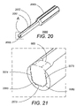
- FIG. 20 is a perspective view of a torque tool that is used to tighten the clamp nuts on the coaxial cable connectors
- FIG. 21 is an enlargement of Area A of FIG. 20 ;
- FIG. 22 is a perspective view showing the use of the torque tool of FIG. 20 on a clamp nut of the eight-position, right-angle, coaxial cable-to-male, push-on connector of FIG. 1 .
- FIG. 1 is a perspective view of an eight-position, right-angle, coaxial cable-to-male, push-on, electrical connector 100 .
- electrical connector may also be referred to as “connector”.
- the connector 100 comprises a housing 105 , preferably a metallic housing.
- the housing 105 has a first face 103 and a second face 204 (see FIG. 2 ).
- the plane of the second face 204 is at a right angle to the plane of the first face 103 .
- Each position of the connector 100 comprises one cable port and one male port.
- the connector 100 has a cable side 101 at the first face 103 of the housing 105 and a male side 202 (see FIG. 2 ) at the second face 204 of the housing.
- a plurality of coaxial cables can be attached to cable ports on the cable side 101 of the connector 100
- plurality of female connectors can be attached to male ports on the male side 202 of the connector.
- the connector 100 has a first set of eight (8) closely-spaced bores 111 – 118 extending into the housing 105 from the first face 103 .
- the connector 100 has eight (8) circular cable ports 121 – 128 on the first face 103 , one (1) at each bore 111 – 118 , respectively.
- a connector assembly 106 includes connector 100 , a cable adapter 120 and a clamp nut 130 .
- Six (6) cable adapters 120 and six (6) clamp nuts 130 are shown removably attached to the housing 105 at cable ports 122 – 125 and 127 – 128 .
- At cable port 121 one (1) additional cable adapter 120 and one (1) additional clamp nut 130 are shown in an exploded view with respect to the connector 100 .
- Each coaxial cable 421 – 428 (see FIG. 4 ), which terminates in a respective cable adapter 120 , is attachable to each cable port 121 – 128 of the connector 100 .
- a respective clamp nut 130 removably secures the coaxial cable-cable adapter combination to each respective cable port 121 – 128 of the connector 100 .
- the housing 105 has a length of about 1.12-inch, a height of about 0.25-inch, and a width of about 0.45-inch.
- the connector 100 occupies less space than eight (8) prior art, single-position, coaxial cable-to-male, push-on connectors.
- Each bore 111 – 118 is spaced about 0.14-inch apart from an adjacent bore.
- Each bore 111 – 118 has internal threads 160 .
- the internal threads 160 are nonstandard threads that are designed to permit a 0.01-inch wall in the housing 105 between adjacent bores 111 – 118 .
- the nonstandard internal threads 160 have a major diameter of about 0.130-inch, a minor diameter of 0.1165-inch to 0.1214-inch, and a pitch diameter of 0.1219-inch to 0.1242-inch, which dimensions are between the standard 5-80 thread and the standard 6-80 thread.
- the smaller standard 5-80 thread, and the requisite smaller diameter bores 111 – 118 would not allow sufficient wall thickness in the clamp nut 130 , or if the wall in the clamp nut were made sufficiently thick, the smaller standard 5-80 thread would not allow enough room within the coupling nut for one of the coaxial cables 421 – 428 , for the cable adapter 120 and for solder (not shown).
- the metallic housing 105 is preferably aluminum alloy 6061-T6, which is the preferred material for applications, such as aerospace applications, where weight reduction is important.
- one (1) connector 100 provides a weight savings compared to eight (8) prior art, single-position, coaxial cable-to-male, push-on connectors.
- the housing 105 has two mounting holes 140 – 141 , preferably countersunk holes, to allow the connector 100 to be securely fastened to another object, such as a bracket attached to a PWB.
- the housing has a key pin 150 protruding from the second face 204 , which helps prevent a user from accidentally installing the connector 100 in a wrong location.
- the key pin 150 is metallic, and more preferably, it is made of passivated CRES-410 or passivated CRES-420.
- FIG. 2 is another perspective view of the eight-position, right-angle, coaxial cable-to-male, push-on, connector 100 , showing a second set of eight (8) closely spaced bores 261 – 268 at the second face 204 of the connector 100 .
- the axis of each bore of the second set of bores 261 – 268 is at a right angle to the axis of each bore of the first set of bores 111 – 118 .
- Corresponding pairs of bores from the first and second sets of bores join to form a set of right-angle junctions (see FIG. 3 ) within the housing 105 .
- the connector 100 has eight (8) circular male ports 271 – 278 , each having a push-on style interface, at each bore 261 – 268 on the second face 204 of the housing 105 .
- FIG. 3 is a cross-sectional view through cut-line 3 — 3 of FIG. 1 showing the internal construction of a position formed by bore 116 and bore 266 , which is representative of the eight (8) positions of connector 100 .
- a right-angle junction 301 is formed where bore 116 meets bore 266 .
- the position includes a metallic center contact 302 that is supported by two dielectrics 308 and 309 .
- the preferred material for the dielectrics 308 and 309 is polytetrafluorethelene (PTFE).
- the dielectric 308 is held in place by a press-fit metallic shroud 314 near the male side 202 of the connector 100 .
- the shroud 314 has a full detent 330 .
- the dielectric 309 is held in place by a press-fit metallic bushing 316 near the cable side 101 of the connector.
- the center contact 302 terminates with a male pin 318 at the male side 202 of the connector 100 and terminates with a female socket contact 320 at the cable side 101 of the connector.
- the position shown in FIG. 3 shows cable port 126 on the cable side 101 of the connector 100 and male port 276 on the male side 202 of the connector.
- FIG. 4 is a perspective view of the connector 100 , including a coaxial cable 421 - 428 removably attached to respective cable ports 121 – 128 of the connector.
- FIG. 5 is a cross-sectional view through cut-line 5 — 5 of FIG. 4 , showing a cross-sectional view of coaxial cable 426 , which is representative of the coaxial cables 421 – 428 .
- the coaxial cable Prior to attaching the clamp nut 130 and the cable adapter 120 to the coaxial cable 426 , the coaxial cable is prepared by selectively removing portions of the jacket 501 , the outer conductor 502 , and the insulation 503 , near the end of coaxial cable to expose a center conductor 504 and the outer conductor 502 , as shown in FIG. 5 . Then, the clamp nut 130 is slid onto the coaxial cable 426 over its jacket 501 .
- the cable adapter 120 is soldered to the outer conductor 502 of the coaxial cable 426 at the two solder holes 511 and 512 .
- the coaxial cable 426 with the attached cable adapter 120 (“coaxial cable-cable adapter combination”) is then inserted into cable port 126 so that the center conductor 504 of the coaxial cable engages within the female socket contact 320 of the connector 100 .
- the clamp nut 130 is threaded into the housing 105 and is tightened with a torque tool 2000 (see FIGS. 20–22 ).
- FIGS. 4 and 5 show the completed attachment of the coaxial cable 426 to the connector 100 . Because the cable adapter 120 is separate from the other portions of the connector 100 , each coaxial cable 421 – 428 is individually field replaceable in the event that it should become worn or damaged.
- the building and testing of cable assemblies is simplified in that there is no need to heat the housing 105 in order to solder the cables 421 – 428 to the cable adapters 120 . Instead, the small thermal mass of the cable adapter 120 speeds up the soldering process. This arrangement also permits open inspection of the solder joint and offers an opportunity to fix any workmanship issues such as solder blobs or cable dielectric extrusion before attachment of each cable 421 – 428 to the connector 100 .
- FIG. 6 is an enlarged perspective view of the clamp nut 130 .
- the clamp nut 130 has nonstandard external threads 660 that match the nonstandard internal threads 160 at the cable ports 121 – 128 of the connector 100 .
- the clamp nut 130 has a cylindrical-shaped passageway 661 along a centerline 662 of the clamp nut for a coaxial cable to pass therethrough.
- the clamp nut 130 has a head 663 having four (4) flat sides 671 – 674 and having four (4) rounded corners 681 – 684 to better accommodate a torque tool 2000 (see FIG. 20 ).
- the head 663 of the clamp nut 130 has a rounded inside circular edge 690 at an entrance to the passageway 661 .
- the rounded inside circular edge 690 acts as a coaxial cable strain relief.
- FIG. 7 is an enlarged perspective view of the cable adapter 120 .
- the cable adapter 120 has a cylindrical-shaped opening 771 along its centerline 772 for passage of one of the coaxial cables 421 – 428 that has been prepared, as explained herein above. Referring to both FIG. 7 and FIG. 5 , the opening 771 has a larger diameter at the entrance of the cable adapter 120 , which is the foreground of FIG. 7 , than at the exit, in order to accommodate, at the entrance, a coaxial cable with its outer conductor 502 intact.
- the cable adapter 120 has two (2) solder holes 511 – 512 for application of solder in order to electrically and mechanically secure the outer conductor 502 of one of the coaxial cables 421 – 428 to the cable adapter.
- FIG. 8 is a perspective view of a known push-on, female-to-female connector, or bullet, 801 , catalog number B1B1-0001-01, manufactured by Corning Gilbert, Inc., which is used to couple the male ports of two connectors, such as connector 100 and connector 1000 (see FIG. 10 ).
- a coaxial cable-to-PWB connector system 1300 in accordance with the invention comprises the connector 100 and the connector 1000 coupled by eight (8) of the female-to-female bullets 801 .
- the coaxial cable-to-PWB connector system 1300 allows the multi-position, coaxial cable-to-male connector 100 to be connected to the multi-position, male-to-PWB connector 1000 via means for compensating for axial or radial, or both axial and radial misalignment of corresponding positions on the connectors.
- FIG. 9 is a perspective view of the connector 100 , including one (1) female-to-female bullet 801 attached to each male, push-on port 271 – 278 of the connector.
- the coaxial cable-to-PWB connector system 1300 in accordance with the invention allows the connectors 100 and 1000 to be coupled to each other in spite of axial or radial, or both axial and radial, misalignment because the bullets can gimbal to accommodate such misalignment.
- the female-to-female bullets 801 when installed in the male ports of the connectors 100 and 1000 , the female-to-female bullets 801 gimbal 0.01-inch radially and 0.01-inch axially, with respect to the connector in which it is installed.
- FIG. 10 is a perspective view of an eight-position, right-angle, push-on, male-to-PWB connector 1000 .
- Each position of the connector 1000 comprises one male port and one PWB port.
- the connector 1000 comprises a housing 1005 , preferably a metallic housing.
- the housing 1005 has a first face 1003 and a second face 1104 (see FIG. 11 ).
- the plane of the second face 1104 is at a right angle to the plane of the first face 1003 .
- Each position of the connector 1000 comprises one male port and one PWB port.
- the connector 1000 has a male side 1001 at the first face 1003 of the housing 1005 and a PWB side 1102 (see FIG. 11 ) at the second face 1104 of the housing.
- the connector 1000 has a first set of eight (8) closely-spaced bores 1011 – 1018 extending into the housing 1005 from the first face 1003 .
- the connector 1000 has eight (8) male, push-on ports 1021 – 1028 on the first face 1003 , one (1) at each bore 1011 – 1018 , respectively.
- the housing 1005 has two mounting holes 1040 – 1041 to allow the connector 1000 to be securely fastened to a PWB.
- FIG. 11 is another perspective view of the eight-position, right-angle, push-on, male-to-PWB connector 1000 , showing a second set of eight (8) closely spaced bores 1161 – 1168 at the second face 1104 of the connector 1000 .
- the axis of each bore of the second set of bores 1161 – 1168 is at a right angle to the axis of each bore of the first set of bores 1011 – 1018 .
- Corresponding pairs of bores from the first and second sets of bores join to form a set of right-angle junctions (see FIG. 12 ) within the housing 1005 .
- the connector 1000 has eight (8) PWB ports 1171 – 1178 on the second face 1104 of the housing 1005 , one (1) PWB port at each bore 1161 – 1168 , respectively.
- Each PWB port 1171 – 1178 comprises a straight PWB pin 1181 – 1188 .
- the housing 1005 of the connector 1000 has a length of about 1.12-inch, a height of about 0.25-inch, and a width of about 0.45-inch.
- Each cable port is spaced apart about 0.14-inch.
- the connector 1000 occupies less space than eight (8) known, single-position, right-angle, push-on, male-to-PWB connectors.
- one (1) connector 1000 provides a weight savings compared to eight (8) known, single-position, right-angle, push-on, male-to-PWB connectors.
- FIG. 12 is a cross-sectional view through cut-line 12 — 12 of FIG. 10 showing the internal construction of a position formed by bore 1016 and bore 1166 , which is representative of the eight (8) positions of connector 1000 .
- a right-angle junction 1201 is formed where bore 1016 meets bore 1166 .
- the position includes a metallic center contact 1202 that is supported by two dielectrics 1208 and 1209 .
- the preferred material for the dielectrics 1208 and 1209 is polytetrafluorethelene (PTFE).
- the dielectric 1208 is held in place by a press-fit metallic shroud 1214 near the male side 1001 of the connector 1000 .
- the shroud 1214 advantageously lacks a detent and preferably has a smooth bore 1230 .
- the dielectric 1209 is held in place by a press-fit metallic bushing 1216 near the PWB side 1102 of the connector 1000 .
- the center contact 1202 terminates with a metallic male pin 1218 at the male side 1001 of the connector 1000 and terminates with a straight PWB pin 1186 that protrudes from the PWB side 1102 of the connector.
- the position shown in FIG. 12 shows male port 1026 on the male side 1001 of the connector 1000 and PWB port 1176 on the PWB side 1102 of the connector.
- FIG. 13 is a perspective view of the coaxial cable-to-male connector 100 mated to the male-to-PWB connector 1000 using eight (8) of the female-to-female bullets 801 , thereby forming the coaxial cable-to-PWB connector system 1300 .
- the male-to-PWB connector 1000 is mounted to a PWB 1301 .
- the coaxial cable-to-PWB connector system 1300 allows a user to make and break a plurality of coaxial cable-to-PWB connections with a single action.
- the coaxial cable-to-PWB connector system 1300 in accordance with the invention allows multiple coaxial cable-to-PWB connections to be made or broken with a single action, and eliminates PWB tolerance stack ups.
- the male-to-PWB connector 1000 allows increased connection density and a smaller PWB footprint.
- the male-to-PWB connector 1000 also allows stronger attachment to the PWB 1301 because use of the mounting holes and a larger solder surface area (compared to single-position connectors), help prevent pad liftoff from the PWB.
- the coaxial cable-to-PWB connector system 1300 simplifies assembly, reduces or eliminates chances of mis-wiring, and simplifies cable harness management.
- FIG. 14 is a perspective view of a four-position, straight, coaxial cable-to-male, push-on, connector 1400 .
- Each position of the connector 1400 comprises one cable port and one male port.
- the connector 1400 comprises a housing 1405 , preferably a metallic housing.
- the housing 1405 has a first face 1403 and a second face 1504 (see FIG. 15 ).
- the plane of the second face 1504 is approximately parallel to the plane of the first face 1403 .
- Each position of the connector 1400 comprises one cable port and one male port.
- the connector 1400 has a cable side 1401 at the first face 1403 of the housing 1405 and a male side 1502 (see FIG. 15 ) at the second face 1504 of the housing.
- the connector 1400 has a set of four (4) closely-spaced bores 1411 – 1414 extending through the housing 1405 between the first face 1403 and the second face 1504 .
- the axis of each bore 1411 – 1414 is at a right angle to the planes of the first face 1403 and the second face 1504 .
- the connector 1400 has four (4) circular cable ports 1421 – 1424 on the first face 1403 , one (1) at each bore 1411 – 1414 .
- Connector assembly 1406 includes the aforementioned connector 1400 along with four (4) cable adapters 120 and four (4) clamp nuts 130 .
- Three (3) cable adapters 120 and three (3) clamp nuts 130 are shown removably attached to the housing 1405 at cable ports 1422 – 1424 .
- the housing 1405 has two mounting holes 1440 – 1441 , to allow the connector 1400 to be securely fastened to another object, such as a bracket on a PWB.
- FIG. 15 is another perspective view of the four-position, straight, coaxial cable-to-male, push-on, connector 1400 , showing the set of four (4) bores 1411 – 1414 at the second face 1504 of the connector 1400 .
- the connector 1400 has four (4) circular male, ports 1571 – 1574 , each having a push-on style interface, at each bore 1411 – 1414 , respectively, on the second face 1504 of the housing 1405 .
- the housing 1405 of the connector 1400 has a length of about 0.96-inch, a height of about 0.152-inch, and a width of about 0.248-inch. Each coaxial port is spaced apart 0.14-inch.
- FIG. 16 is a cross-sectional view through cut-line 16 — 16 of FIG. 14 showing the internal construction of a position formed by bore 1412 , which is representative of the four (4) positions of connector 1400 .
- the position includes a metallic center contact 1602 that is supported by two dielectrics 1608 and 1609 .
- the preferred material for the dielectrics 1608 and 1609 is polytetrafluorethelene (PTFE).
- PTFE polytetrafluorethelene
- the dielectric 1608 is held in place by a press-fit metallic shroud 1614 near the male side 1502 of the connector 1400 .
- the dielectric 1609 is held in place by a press-fit metallic bushing 1616 near the cable side 1401 of the connector 1400 .
- the shroud 1614 has a full detent 1630 for securely holding a female-to-female bullet 801 .
- the center contact 1602 terminates with a male pin 1618 at the male side 1502 of the connector 1400 and terminates with a female socket contact 1620 at the cable side 1401 of the connector.
- the position shown in FIG. 16 shows cable port 1422 on the cable side 1401 of the connector 1400 and male port 1572 on the male side 1502 of the connector.
- FIG. 17 is a perspective view of a four-position, straight, push-on, male-to-PWB connector 1700 .
- Each position of the connector 1700 comprises one male port and one PWB port.
- the connector 1700 comprises a housing 1705 , preferably a metallic housing.
- the housing 1705 has a first face 1703 and a second face 1804 (see FIG. 18 ).
- the plane of the second face 1804 is approximately parallel to the plane of the first face 1703 .
- Each position of the connector 1700 comprises one male port and one PWB port.
- the connector 1700 has a male side, 1701 at the first face 1703 of the housing 1705 and a PWB side 1802 (see FIG. 18 ) at the second face 1804 of the housing.
- the connector 1700 has a set of four (4) closely-spaced bores 1711 – 1714 extending through the housing 1705 between the first face 1703 and the second face 1804 .
- the axis of each bore 1711 – 1714 is at a right angle to the planes of the first face 1703 and the second face 1804 .
- the connector 1700 has four (4) male, push-on ports 1721 – 1724 on the first face 1703 , one (1) at each bore 1711 – 1714 .
- the housing 1705 has a mounting hole 1740 to allow the connector 1700 to be securely fastened to a PWB.
- FIG. 18 is another perspective view of the four-position, straight, push-on, male-to-PWB connector 1700 , showing the set of four (4) bores 1711 – 1714 at the second face 1804 of the connector 1700 .
- the connector 1700 has four (4) PWB ports 1871 – 1874 , one (1) at each bore 1711 – 1714 on the second face 1804 of the housing 1705 .
- Each PWB port 1871 – 1874 comprises a straight PWB pin 1881 – 1884 .
- the housing of the connector 1700 has a length of about 0.56-inch, a height of about 0.16-inch, and a width of about 0.35-inch.
- Each cable port is spaced apart 0.14-inch.
- the connector 1700 occupies less space than four (4) known, single-position, straight, push-on, male-to-PWB connectors.
- four (4) known, single-position GPPO PCB Mount connectors catalog number B008-L13–01, manufactured by Corning Gilbert, Inc., occupy a larger space having a height of 0.194-inch and having a total length of 0.61-inch, assuming that there are three (3) small 0.01-inch spaces between the four (4) single-position connectors.
- one (1) connector 1700 provides a weight savings compared to four (4) known, single-position, straight, push-on, male-to-PWB connectors.
- the coaxial cable-to-PWB connector system 1300 alternatively comprises connector 1400 and connector 1700 coupled by four (4) of the female-to-female bullets 801 .
- FIG. 19 is a cross-sectional view through cut-line 19 — 19 of FIG. 17 showing the internal construction of a position formed by bore 1712 , which is representative of the four (4) positions of connector 1700 .
- the position includes a metallic center contact 1902 that is supported by a dielectric 1909 .
- the preferred material for the dielectric 1909 is polytetrafluorethelene (PTFE).
- PTFE polytetrafluorethelene
- the dielectric 1909 is held in place by a press-fit metallic shroud 1914 near the male side 1701 of the connector 1700 .
- the shroud 1914 advantageously lacks a detent and has a smooth bore 1930 .
- the center contact 1902 terminates with a male pin 1918 at the male side 1701 of the connector 1700 and terminates with the straight PWB pin 1882 that protrudes from the PWB side 1802 of the connector.
- the position shown in FIG. 19 shows male port 1722 on the male side 1701 of the connector 1400 and PWB port 1872 on the PWB side 1802 of the connector.
- the connectors 100 , 1000 , 1400 and 1700 in accordance with the invention have outer corners (for example, corners 1951 – 1955 of connector 1700 ) that are rounded to a radius of approximately 0.01-inch.
- the aluminum housing 105 , 1005 , 1405 , 1705 of the connectors 100 , 1000 , 1400 and 1700 is gold plated to improve solderability, low contact resistance, and corrosion protection.
- the rounded outer edges of the connectors 100 , 1000 , 1400 and 1700 help to prevent nicks from occurring at the edges while the connectors are being tumbled during a gold-plating operation. Note that in the drawings, the rounded outer edges are shown only in the cross-sectional views of the connectors, which are enlargements of the perspective views of the connectors.
- FIG. 20 is a perspective view of a torque tool 2000 that is used to tighten the clamp nuts 130 on the cable connectors 100 and 1400 .
- the torque tool 2000 is metallic for strength.
- the torque tool comprises an elongated hollow segment 2001 , a handle 2003 at one end adapted for attachment to a standard 1 ⁇ 4-inch hex tool, and a tip 2005 at another end opposite the handle.
- the torque tool 2000 has a slot 2002 extending longitudinally from the tip 2005 to at least the handle 2003 .
- the slot 2002 has a width that is slightly larger than the diameter of one of the coaxial cables 421 – 428 , thereby allowing a coaxial cable to pass therethrough.
- the elongated hollow segment 2001 has an outer diameter at the tip 2005 that is advantageously small enough to fit between closely-spaced, clamp nuts 130 at adjacent cable ports 121 – 128 .
- FIG. 21 is an enlargement of Area A of FIG. 20 , including the head 663 of a clamp nut 130 (shown in dotted lines).
- the inside of the tip 2005 of the torque tool 2000 has three (3) flat surfaces 2072 – 2074 corresponding to three (3) of the four (4) flat sides 671 – 674 of the head 663 of the clamp nut 130 .
- the inside of the tip 2005 of the torque tool 2000 also has two 45° chamfers 2082 and 2083 corresponding to two (2) of the four (4) rounded corners 681 – 684 of the head 663 of the clamp nut 130 .
- the torque tool 2000 can advantageously be constructed with the two 45° chamfers 2082 and 2083 . Consequently, the torque tool 2000 can have thicker, stronger walls at the areas of the tip 2005 that contact the rounded corners 681 - 684 of the head 663 of the clamp nut 130 , which are the areas where strength is most needed, without increasing the outer diameter of the elongated hollow segment 2001 .
- FIG. 22 is a perspective view showing the use of the torque tool 2000 on a clamp nut 130 of the connector 100 , and showing coaxial cable 425 advantageously passing through the slot 2002 in the torque tool.
- a connector in accordance with the invention simplifies the testing of a coaxial cable assembly, which comprises a plurality of coaxial cables, because each individual coaxial cable can be rapidly tested.
- a coaxial cable assembly which comprises a plurality of coaxial cables, because each individual coaxial cable can be rapidly tested.
- one of the coaxial cables 421 – 428 having a newly soldered cable adapter 120 on its end, is simply inserted into a corresponding at least one cable port 121 – 128 and 1421 – 1424 , to quickly test the VSWR of the coaxial cable-cable adapter combination (advantageously, without needing to affix the clamp nut 130 to the coaxial cable-to-male connector).
- the connectors 100 and 1400 are preferably sized to accept a coaxial cable 421 – 428 of the 50-ohm, 0.047-inch, flexible type.
- the connectors 100 and 1400 are used with other sizes and types of coaxial cables, in which case the connectors are sized accordingly.
- a connector in accordance with the invention allows multiple coaxial cables 421 – 428 to be connected to the PWB 1301 or other such devices, while still maintaining the versatility of allowing individual coaxial cables to be easily replaced in the field if they should become worn or damaged.
- the connectors 100 , 1000 , 1400 and 1700 preferably work with the standard SMP interface and the standard SMPM interface.
- the connectors 100 , 1000 , 1400 and 1700 are used at microwave radio frequencies up to 40-GHz in an SMP version, up to 65-GHz in an SMPM version and up to 100-GHz in a CGP or G3PO version manufactured by Corning Gilbert Inc.
- a connector in accordance with the invention is not limited to having four (4) or eight (8) ports, but may have a larger or a smaller number of ports.
Abstract
Description
- 100 Eight-position, right-angle, coaxial cable-to-male, push-on connector
- 101 Cable side of connector
- 103 First face of housing
- 105 Housing
- 106 Connector assembly
- 111–118 First set of bores
- 120 Cable adapter
- 121–128 Cable ports
- 130 Clamp nut
- 140–141 Mounting holes
- 150 Key pin
- 160 Nonstandard internal threads
- 202 Male side of connector
- 204 Second face of housing
- 261–268 Second set of bores
- 271–278 Male push-on ports
- 301 Right-angle junction
- 302 Center contact
- 308–309 Dielectrics
- 314 Shroud
- 316 Bushing
- 318 Male pin
- 320 Female socket contact
- 330 Full detent
- 421–428 Coaxial cable
- 501 Jacket
- 502 Outer conductor
- 503 Insulation
- 504 Center conductor
- 511–512 Solder holes
- 660 Nonstandard external threads
- 661 Passageway
- 662 Centerline of clamp nut
- 663 Head of clamp nut
- 671–674 Flat sides of head
- 681–684 Rounded corners of head
- 690 Rounded inside circular edge
- 771 Opening
- 772 Centerline of cable adapter
- 801 Female-to-female bullet
- 1000 Eight-position, right-angle, push-on, male-to-PWB connector
- 1001 Male side of connector
- 1003 First face of housing
- 1005 Housing
- 1011–1018 First set of bores
- 1021–1028 Male, push-on ports
- 1040–1041 Mounting holes
- 1102 PWB side of connector
- 1104 Second face of housing
- 1161–1168 Second set of bores
- 1171–1178 PWB ports
- 1181–1188 Straight PWB pin
- 1201 Right-angle junction
- 1202 Center contact
- 1208–1209 Dielectrics
- 1214 Shroud
- 1216 Bushing
- 1218 Male pin
- 1230 Smooth bore
- 1300 Coaxial cable-to-PWB connector system
- 1301 Printed Wiring Board (PWB)
- 1400 Four-position, straight, coaxial cable-to-male, push-on connector
- 1401 Cable side of connector
- 1403 First face of housing
- 1405 Housing
- 1406 Connector assembly
- 1411–1414 Set of bores
- 1421–1424 Cable ports
- 1440–1441 Mounting holes
- 1502 Male side of connector
- 1504 Second face of housing
- 1571–1574 Male push-on ports
- 1602 Center contact
- 1608–1609 Dielectrics
- 1614 Shroud
- 1616 Bushing
- 1618 Male pin
- 1620 Female socket contact
- 1630 Full detent
- 1700 Four-position, straight, push-on, male-to-PWB connector
- 1701 Male side of connector
- 1703 First face of housing
- 1705 Housing
- 1711–1714 Set of bores
- 1721–1724 Male push-on ports
- 1740 Mounting holm
- 1802 PWB side of connector
- 1804 Second face of housing
- 1871–1874 PWB ports
- 1881–1884 Straight PWB pin
- 1902 Center contact
- 1909 Dielectric
- 1914 Shroud
- 1918 Male pin
- 1930 Smooth bore
- 1951–1954 Rounded outer corners
- 2000 Torque tool
- 2001 Elongated hollow segment
- 2002 Slot
- 2003 Handle
- 2005 Tip
- 2072–2074 Flat surfaces
- 2082–2083 Chamfers
Claims (38)
Priority Applications (3)
| Application Number | Priority Date | Filing Date | Title |
|---|---|---|---|
| US10/967,046 US7165974B2 (en) | 2004-10-14 | 2004-10-14 | Multiple-position push-on electrical connector |
| EP05810838A EP1803198B1 (en) | 2004-10-14 | 2005-10-12 | Multiple-position push-on electrical connector |
| PCT/US2005/036905 WO2006044580A1 (en) | 2004-10-14 | 2005-10-12 | Multiple-position push-on electrical connector |
Applications Claiming Priority (1)
| Application Number | Priority Date | Filing Date | Title |
|---|---|---|---|
| US10/967,046 US7165974B2 (en) | 2004-10-14 | 2004-10-14 | Multiple-position push-on electrical connector |
Publications (2)
| Publication Number | Publication Date |
|---|---|
| US20060084286A1 US20060084286A1 (en) | 2006-04-20 |
| US7165974B2 true US7165974B2 (en) | 2007-01-23 |
Family
ID=35589651
Family Applications (1)
| Application Number | Title | Priority Date | Filing Date |
|---|---|---|---|
| US10/967,046 Active US7165974B2 (en) | 2004-10-14 | 2004-10-14 | Multiple-position push-on electrical connector |
Country Status (3)
| Country | Link |
|---|---|
| US (1) | US7165974B2 (en) |
| EP (1) | EP1803198B1 (en) |
| WO (1) | WO2006044580A1 (en) |
Cited By (55)
| Publication number | Priority date | Publication date | Assignee | Title |
|---|---|---|---|---|
| US7217137B1 (en) * | 2005-11-18 | 2007-05-15 | Hirose Electric Co., Ltd. | Coaxial connector having a switch |
| US20080045043A1 (en) * | 2004-07-10 | 2008-02-21 | Gigalane Co., Ltd. | Right Angle Coaxial Connector Mountable on Pcb |
| US20080176433A1 (en) * | 2007-01-22 | 2008-07-24 | Hon Hai Precision Industry Co., Ltd. | Connector adapter |
| US20080264668A1 (en) * | 2007-04-30 | 2008-10-30 | Trentent Tye | Angled conductor extender |
| US7500873B1 (en) | 2008-05-16 | 2009-03-10 | Corning Gilbert Inc. | Snap-on coaxial cable connector |
| US20100015850A1 (en) * | 2008-07-15 | 2010-01-21 | Casey Roy Stein | Low-profile mounted push-on connector |
| US20100062638A1 (en) * | 2007-10-08 | 2010-03-11 | Winchester Electronics Corporation | Modular interconnect apparatus |
| US20100255688A1 (en) * | 2006-01-17 | 2010-10-07 | Laird Technologies Gmbh | Rf connector mounting means |
| US20110181377A1 (en) * | 2010-01-22 | 2011-07-28 | Kenneth Vanhille | Thermal management |
| US20110181376A1 (en) * | 2010-01-22 | 2011-07-28 | Kenneth Vanhille | Waveguide structures and processes thereof |
| US20110210807A1 (en) * | 2003-03-04 | 2011-09-01 | Sherrer David W | Coaxial waveguide microstructures and methods of formation thereof |
| US20120021645A1 (en) * | 2009-03-30 | 2012-01-26 | Tyco Electronics Uk Ltd. | Coaxial connector with inner shielding arrangement and method of assembling one |
| US20120058672A1 (en) * | 2010-09-02 | 2012-03-08 | Tyco Electronics Corporation | Electrical connector having shaped dielectric insert for controlling impedance |
| US20120122325A1 (en) * | 2010-11-16 | 2012-05-17 | Compal Electronics, Inc. | Connecting port |
| US8542079B2 (en) | 2007-03-20 | 2013-09-24 | Nuvotronics, Llc | Coaxial transmission line microstructure including an enlarged coaxial structure for transitioning to an electrical connector |
| US8814601B1 (en) | 2011-06-06 | 2014-08-26 | Nuvotronics, Llc | Batch fabricated microconnectors |
| US8866300B1 (en) | 2011-06-05 | 2014-10-21 | Nuvotronics, Llc | Devices and methods for solder flow control in three-dimensional microstructures |
| US8888526B2 (en) | 2010-08-10 | 2014-11-18 | Corning Gilbert, Inc. | Coaxial cable connector with radio frequency interference and grounding shield |
| US8933769B2 (en) | 2006-12-30 | 2015-01-13 | Nuvotronics, Llc | Three-dimensional microstructures having a re-entrant shape aperture and methods of formation |
| US8992250B1 (en) * | 2013-03-15 | 2015-03-31 | Megaphase, Llc | Clockable cable adapter |
| US9024417B2 (en) | 2007-03-20 | 2015-05-05 | Nuvotronics, Llc | Integrated electronic components and methods of formation thereof |
| US9048599B2 (en) | 2013-10-28 | 2015-06-02 | Corning Gilbert Inc. | Coaxial cable connector having a gripping member with a notch and disposed inside a shell |
| US9054471B2 (en) | 2012-02-03 | 2015-06-09 | Megaphase, Llc | Coaxial angled adapter |
| US9071019B2 (en) | 2010-10-27 | 2015-06-30 | Corning Gilbert, Inc. | Push-on cable connector with a coupler and retention and release mechanism |
| US9136654B2 (en) | 2012-01-05 | 2015-09-15 | Corning Gilbert, Inc. | Quick mount connector for a coaxial cable |
| US9147963B2 (en) | 2012-11-29 | 2015-09-29 | Corning Gilbert Inc. | Hardline coaxial connector with a locking ferrule |
| US9153911B2 (en) | 2013-02-19 | 2015-10-06 | Corning Gilbert Inc. | Coaxial cable continuity connector |
| US9166348B2 (en) | 2010-04-13 | 2015-10-20 | Corning Gilbert Inc. | Coaxial connector with inhibited ingress and improved grounding |
| US9172154B2 (en) | 2013-03-15 | 2015-10-27 | Corning Gilbert Inc. | Coaxial cable connector with integral RFI protection |
| US9190744B2 (en) | 2011-09-14 | 2015-11-17 | Corning Optical Communications Rf Llc | Coaxial cable connector with radio frequency interference and grounding shield |
| US9287659B2 (en) | 2012-10-16 | 2016-03-15 | Corning Optical Communications Rf Llc | Coaxial cable connector with integral RFI protection |
| US9306254B1 (en) | 2013-03-15 | 2016-04-05 | Nuvotronics, Inc. | Substrate-free mechanical interconnection of electronic sub-systems using a spring configuration |
| US9306255B1 (en) | 2013-03-15 | 2016-04-05 | Nuvotronics, Inc. | Microstructure including microstructural waveguide elements and/or IC chips that are mechanically interconnected to each other |
| US9325044B2 (en) | 2013-01-26 | 2016-04-26 | Nuvotronics, Inc. | Multi-layer digital elliptic filter and method |
| US9407016B2 (en) | 2012-02-22 | 2016-08-02 | Corning Optical Communications Rf Llc | Coaxial cable connector with integral continuity contacting portion |
| US9525220B1 (en) | 2015-11-25 | 2016-12-20 | Corning Optical Communications LLC | Coaxial cable connector |
| US9548572B2 (en) | 2014-11-03 | 2017-01-17 | Corning Optical Communications LLC | Coaxial cable connector having a coupler and a post with a contacting portion and a shoulder |
| US9548557B2 (en) | 2013-06-26 | 2017-01-17 | Corning Optical Communications LLC | Connector assemblies and methods of manufacture |
| US9590287B2 (en) | 2015-02-20 | 2017-03-07 | Corning Optical Communications Rf Llc | Surge protected coaxial termination |
| US9762008B2 (en) | 2013-05-20 | 2017-09-12 | Corning Optical Communications Rf Llc | Coaxial cable connector with integral RFI protection |
| US9859631B2 (en) | 2011-09-15 | 2018-01-02 | Corning Optical Communications Rf Llc | Coaxial cable connector with integral radio frequency interference and grounding shield |
| US20180076583A1 (en) * | 2016-09-14 | 2018-03-15 | Tyco Electronics Corporation | Rf connector system having connector cavities with side openings |
| US9993982B2 (en) | 2011-07-13 | 2018-06-12 | Nuvotronics, Inc. | Methods of fabricating electronic and mechanical structures |
| US10033122B2 (en) | 2015-02-20 | 2018-07-24 | Corning Optical Communications Rf Llc | Cable or conduit connector with jacket retention feature |
| US10211547B2 (en) | 2015-09-03 | 2019-02-19 | Corning Optical Communications Rf Llc | Coaxial cable connector |
| US10243282B1 (en) * | 2018-05-09 | 2019-03-26 | Huang Liang Technologies Co., Ltd. | Linking rod clamping mechanism for connecting coaxial connector with printed circuit board |
| US10290958B2 (en) | 2013-04-29 | 2019-05-14 | Corning Optical Communications Rf Llc | Coaxial cable connector with integral RFI protection and biasing ring |
| US10310009B2 (en) | 2014-01-17 | 2019-06-04 | Nuvotronics, Inc | Wafer scale test interface unit and contactors |
| US10319654B1 (en) | 2017-12-01 | 2019-06-11 | Cubic Corporation | Integrated chip scale packages |
| CN110098582A (en) * | 2019-04-08 | 2019-08-06 | 赵子花 | A kind of high-voltage wiring harness arragement construction that the thin pin needle slot cover button of new energy vehicle is anti-bending |
| US10497511B2 (en) | 2009-11-23 | 2019-12-03 | Cubic Corporation | Multilayer build processes and devices thereof |
| US10511073B2 (en) | 2014-12-03 | 2019-12-17 | Cubic Corporation | Systems and methods for manufacturing stacked circuits and transmission lines |
| US10756455B2 (en) | 2005-01-25 | 2020-08-25 | Corning Optical Communications Rf Llc | Electrical connector with grounding member |
| US10847469B2 (en) | 2016-04-26 | 2020-11-24 | Cubic Corporation | CTE compensation for wafer-level and chip-scale packages and assemblies |
| US20210195733A1 (en) * | 2019-01-28 | 2021-06-24 | Eagle Technology, Llc | Interconnect device |
Families Citing this family (13)
| Publication number | Priority date | Publication date | Assignee | Title |
|---|---|---|---|---|
| US20070262725A1 (en) * | 2004-07-29 | 2007-11-15 | Nexxus Lighting, Inc. | Modular Lighting System |
| US7327930B2 (en) * | 2004-07-29 | 2008-02-05 | Nexxus Lighting, Inc. | Modular light-emitting diode lighting system |
| US7416415B2 (en) * | 2006-06-12 | 2008-08-26 | Corning Gilbert Inc. | Multiple position push-on electrical connector and a mating connector therefor |
| US8317539B2 (en) * | 2009-08-14 | 2012-11-27 | Corning Gilbert Inc. | Coaxial interconnect and contact |
| US8597050B2 (en) * | 2009-12-21 | 2013-12-03 | Corning Gilbert Inc. | Digital, small signal and RF microwave coaxial subminiature push-on differential pair system |
| EP2680372B1 (en) | 2012-06-29 | 2017-06-07 | Corning Optical Communications RF LLC | Multi-sectional insulator for coaxial connector |
| EP2680371B1 (en) | 2012-06-29 | 2018-04-11 | Corning Optical Communications RF LLC | Tubular insulator for coaxial connector |
| TWM458003U (en) * | 2013-02-25 | 2013-07-21 | Grand Tek Technology Co Ltd | Integrated type radio frequency connector |
| US9661776B2 (en) * | 2014-01-03 | 2017-05-23 | Te Connectivity Corporation | Mounting assembly and backplane communication system |
| DE102015113786B4 (en) * | 2015-08-20 | 2019-01-31 | Harting Electric Gmbh & Co. Kg | Connector and method for its manufacture |
| US10243301B2 (en) * | 2017-03-15 | 2019-03-26 | Raytheon Company | Blind mate connector housing and assembly |
| US10542329B2 (en) | 2017-05-19 | 2020-01-21 | Ppc Broadband, Inc. | Cable junction devices |
| CN114268002A (en) * | 2021-12-28 | 2022-04-01 | 江苏沃能电气科技有限公司 | Water-inflow-preventing plugging process based on right-angled bent bus joint |
Citations (28)
| Publication number | Priority date | Publication date | Assignee | Title |
|---|---|---|---|---|
| US4605269A (en) * | 1984-06-20 | 1986-08-12 | Amp Incorporated | Printed circuit board header having coaxial sockets therein and matable coaxial plug housing |
| US4772222A (en) * | 1987-10-15 | 1988-09-20 | Amp Incorporated | Coaxial LMC connector |
| US4895521A (en) | 1989-01-13 | 1990-01-23 | Amp Incorporated | Multi-port coaxial connector assembly |
| US4900258A (en) | 1989-06-12 | 1990-02-13 | Amp Incorporated | Multi-port coaxial printed circuit board connector |
| US5046952A (en) | 1990-06-08 | 1991-09-10 | Amp Incorporated | Right angle connector for mounting to printed circuit board |
| US5122063A (en) * | 1991-02-06 | 1992-06-16 | Alliance Research Corporation | Adjustable electrical connector |
| US5203717A (en) | 1991-05-28 | 1993-04-20 | Woven Electronics Corporation | Coax connector assembly |
| US5273443A (en) | 1993-04-22 | 1993-12-28 | The Whitaker Corporation | High density connector |
| EP0582960A1 (en) | 1992-08-12 | 1994-02-16 | Siemens Aktiengesellschaft | HF coaxial plug connection |
| US5295863A (en) | 1992-09-17 | 1994-03-22 | Arrowsmith Shelburne, Inc. | Electrical connector for coaxial cable |
| US5611707A (en) | 1994-01-13 | 1997-03-18 | Radiall | Microminiature coaxial connector which locks by snap-fastening |
| WO1998033243A2 (en) | 1997-01-28 | 1998-07-30 | Siemens Electromechanical Components Gmbh & Co. Kg | Hf coaxial plug-in connector |
| US5842872A (en) | 1995-06-30 | 1998-12-01 | The Whitaker Corporation | Modular right angle board mountable coaxial connector |
| US5890926A (en) | 1997-03-26 | 1999-04-06 | The Whitaker Corporation | Cable bend controller |
| US5906511A (en) | 1994-10-17 | 1999-05-25 | The Whitaker Corporation | Multi-position coaxial cable connector |
| US6071127A (en) | 1997-02-25 | 2000-06-06 | Siemens Aktiengesellschaft | HF coaxial connector having a plug module and a socket module |
| US20010004555A1 (en) | 1999-12-16 | 2001-06-21 | Dietmar Harting | Plug connector |
| US6309251B1 (en) * | 2000-06-01 | 2001-10-30 | Antronix, Inc. | Auto-seizing coaxial cable port for an electrical device |
| US6338653B1 (en) | 2000-07-07 | 2002-01-15 | Hon Hai Precision Ind. Co., Ltd. | Surface mount cable connector |
| US6344736B1 (en) * | 1999-07-22 | 2002-02-05 | Tensolite Company | Self-aligning interface apparatus for use in testing electrical |
| US20020137370A1 (en) | 1999-12-16 | 2002-09-26 | Dietmar Harting | Plug connector |
| US6547593B1 (en) | 2000-08-07 | 2003-04-15 | Gore Enterprise Holdings, Inc. | Sub-miniature, high speed coaxial pin interconnection system |
| US6679728B1 (en) * | 2002-12-27 | 2004-01-20 | Insert Enterprise Co., Ltd. | Mini BNC connector |
| US6692262B1 (en) | 2002-08-12 | 2004-02-17 | Huber & Suhner, Inc. | Connector assembly for coupling a plurality of coaxial cables to a substrate while maintaining high signal throughput and providing long-term serviceability |
| US20040038586A1 (en) | 2002-08-22 | 2004-02-26 | Hall Richard D. | High frequency, blind mate, coaxial interconnect |
| US20040092165A1 (en) | 2002-11-07 | 2004-05-13 | Michael Holland | F-type connector installation and removal tool |
| US20040137790A1 (en) | 2003-01-13 | 2004-07-15 | Andrew Corporation | Right angle coaxial connector |
| US20040203283A1 (en) | 2003-04-09 | 2004-10-14 | Insert Enterprise Co., Ltd. | Module type mini bnc connector |
-
2004
- 2004-10-14 US US10/967,046 patent/US7165974B2/en active Active
-
2005
- 2005-10-12 WO PCT/US2005/036905 patent/WO2006044580A1/en active Application Filing
- 2005-10-12 EP EP05810838A patent/EP1803198B1/en active Active
Patent Citations (28)
| Publication number | Priority date | Publication date | Assignee | Title |
|---|---|---|---|---|
| US4605269A (en) * | 1984-06-20 | 1986-08-12 | Amp Incorporated | Printed circuit board header having coaxial sockets therein and matable coaxial plug housing |
| US4772222A (en) * | 1987-10-15 | 1988-09-20 | Amp Incorporated | Coaxial LMC connector |
| US4895521A (en) | 1989-01-13 | 1990-01-23 | Amp Incorporated | Multi-port coaxial connector assembly |
| US4900258A (en) | 1989-06-12 | 1990-02-13 | Amp Incorporated | Multi-port coaxial printed circuit board connector |
| US5046952A (en) | 1990-06-08 | 1991-09-10 | Amp Incorporated | Right angle connector for mounting to printed circuit board |
| US5122063A (en) * | 1991-02-06 | 1992-06-16 | Alliance Research Corporation | Adjustable electrical connector |
| US5203717A (en) | 1991-05-28 | 1993-04-20 | Woven Electronics Corporation | Coax connector assembly |
| EP0582960A1 (en) | 1992-08-12 | 1994-02-16 | Siemens Aktiengesellschaft | HF coaxial plug connection |
| US5295863A (en) | 1992-09-17 | 1994-03-22 | Arrowsmith Shelburne, Inc. | Electrical connector for coaxial cable |
| US5273443A (en) | 1993-04-22 | 1993-12-28 | The Whitaker Corporation | High density connector |
| US5611707A (en) | 1994-01-13 | 1997-03-18 | Radiall | Microminiature coaxial connector which locks by snap-fastening |
| US5906511A (en) | 1994-10-17 | 1999-05-25 | The Whitaker Corporation | Multi-position coaxial cable connector |
| US5842872A (en) | 1995-06-30 | 1998-12-01 | The Whitaker Corporation | Modular right angle board mountable coaxial connector |
| WO1998033243A2 (en) | 1997-01-28 | 1998-07-30 | Siemens Electromechanical Components Gmbh & Co. Kg | Hf coaxial plug-in connector |
| US6071127A (en) | 1997-02-25 | 2000-06-06 | Siemens Aktiengesellschaft | HF coaxial connector having a plug module and a socket module |
| US5890926A (en) | 1997-03-26 | 1999-04-06 | The Whitaker Corporation | Cable bend controller |
| US6344736B1 (en) * | 1999-07-22 | 2002-02-05 | Tensolite Company | Self-aligning interface apparatus for use in testing electrical |
| US20020137370A1 (en) | 1999-12-16 | 2002-09-26 | Dietmar Harting | Plug connector |
| US20010004555A1 (en) | 1999-12-16 | 2001-06-21 | Dietmar Harting | Plug connector |
| US6309251B1 (en) * | 2000-06-01 | 2001-10-30 | Antronix, Inc. | Auto-seizing coaxial cable port for an electrical device |
| US6338653B1 (en) | 2000-07-07 | 2002-01-15 | Hon Hai Precision Ind. Co., Ltd. | Surface mount cable connector |
| US6547593B1 (en) | 2000-08-07 | 2003-04-15 | Gore Enterprise Holdings, Inc. | Sub-miniature, high speed coaxial pin interconnection system |
| US6692262B1 (en) | 2002-08-12 | 2004-02-17 | Huber & Suhner, Inc. | Connector assembly for coupling a plurality of coaxial cables to a substrate while maintaining high signal throughput and providing long-term serviceability |
| US20040038586A1 (en) | 2002-08-22 | 2004-02-26 | Hall Richard D. | High frequency, blind mate, coaxial interconnect |
| US20040092165A1 (en) | 2002-11-07 | 2004-05-13 | Michael Holland | F-type connector installation and removal tool |
| US6679728B1 (en) * | 2002-12-27 | 2004-01-20 | Insert Enterprise Co., Ltd. | Mini BNC connector |
| US20040137790A1 (en) | 2003-01-13 | 2004-07-15 | Andrew Corporation | Right angle coaxial connector |
| US20040203283A1 (en) | 2003-04-09 | 2004-10-14 | Insert Enterprise Co., Ltd. | Module type mini bnc connector |
Non-Patent Citations (1)
| Title |
|---|
| Corning Gilbert, Inc., 2002 Microwave Products Catalog, Feb. 2002, p. 20. |
Cited By (96)
| Publication number | Priority date | Publication date | Assignee | Title |
|---|---|---|---|---|
| US8742874B2 (en) | 2003-03-04 | 2014-06-03 | Nuvotronics, Llc | Coaxial waveguide microstructures having an active device and methods of formation thereof |
| US20110210807A1 (en) * | 2003-03-04 | 2011-09-01 | Sherrer David W | Coaxial waveguide microstructures and methods of formation thereof |
| US9312589B2 (en) | 2003-03-04 | 2016-04-12 | Nuvotronics, Inc. | Coaxial waveguide microstructure having center and outer conductors configured in a rectangular cross-section |
| US10074885B2 (en) | 2003-03-04 | 2018-09-11 | Nuvotronics, Inc | Coaxial waveguide microstructures having conductors formed by plural conductive layers |
| US7540771B2 (en) * | 2004-07-10 | 2009-06-02 | Gigalane Co., Ltd | Right angle coaxial connector mountable on PCB |
| US20080045043A1 (en) * | 2004-07-10 | 2008-02-21 | Gigalane Co., Ltd. | Right Angle Coaxial Connector Mountable on Pcb |
| US10756455B2 (en) | 2005-01-25 | 2020-08-25 | Corning Optical Communications Rf Llc | Electrical connector with grounding member |
| US7217137B1 (en) * | 2005-11-18 | 2007-05-15 | Hirose Electric Co., Ltd. | Coaxial connector having a switch |
| US20070117435A1 (en) * | 2005-11-18 | 2007-05-24 | Hirose Electric Co., Ltd. | Coaxial connector having a switch |
| US20100255688A1 (en) * | 2006-01-17 | 2010-10-07 | Laird Technologies Gmbh | Rf connector mounting means |
| US7909612B2 (en) * | 2006-01-17 | 2011-03-22 | Laird Technologies, Inc. | RF connector mounting means |
| US9515364B1 (en) | 2006-12-30 | 2016-12-06 | Nuvotronics, Inc. | Three-dimensional microstructure having a first dielectric element and a second multi-layer metal element configured to define a non-solid volume |
| US8933769B2 (en) | 2006-12-30 | 2015-01-13 | Nuvotronics, Llc | Three-dimensional microstructures having a re-entrant shape aperture and methods of formation |
| US20080176433A1 (en) * | 2007-01-22 | 2008-07-24 | Hon Hai Precision Industry Co., Ltd. | Connector adapter |
| US10431521B2 (en) | 2007-03-20 | 2019-10-01 | Cubic Corporation | Integrated electronic components and methods of formation thereof |
| US9570789B2 (en) | 2007-03-20 | 2017-02-14 | Nuvotronics, Inc | Transition structure between a rectangular coaxial microstructure and a cylindrical coaxial cable using step changes in center conductors thereof |
| US10002818B2 (en) | 2007-03-20 | 2018-06-19 | Nuvotronics, Inc. | Integrated electronic components and methods of formation thereof |
| US8542079B2 (en) | 2007-03-20 | 2013-09-24 | Nuvotronics, Llc | Coaxial transmission line microstructure including an enlarged coaxial structure for transitioning to an electrical connector |
| US9024417B2 (en) | 2007-03-20 | 2015-05-05 | Nuvotronics, Llc | Integrated electronic components and methods of formation thereof |
| US9000863B2 (en) | 2007-03-20 | 2015-04-07 | Nuvotronics, Llc. | Coaxial transmission line microstructure with a portion of increased transverse dimension and method of formation thereof |
| US20080264668A1 (en) * | 2007-04-30 | 2008-10-30 | Trentent Tye | Angled conductor extender |
| US7896656B2 (en) * | 2007-10-08 | 2011-03-01 | Winchester Electronics Corporation | Modular interconnect apparatus |
| US20110217871A1 (en) * | 2007-10-08 | 2011-09-08 | Winchester Electronics Corporation | Modular interconnect apparatus |
| US8157572B2 (en) * | 2007-10-08 | 2012-04-17 | Winchester Electronics Corporation | Modular interconnect apparatus |
| US20100062638A1 (en) * | 2007-10-08 | 2010-03-11 | Winchester Electronics Corporation | Modular interconnect apparatus |
| US7500873B1 (en) | 2008-05-16 | 2009-03-10 | Corning Gilbert Inc. | Snap-on coaxial cable connector |
| WO2010008516A1 (en) * | 2008-07-15 | 2010-01-21 | Corning Gilbert Inc. | Low-profile mounted push-on connector |
| US20100015850A1 (en) * | 2008-07-15 | 2010-01-21 | Casey Roy Stein | Low-profile mounted push-on connector |
| US20120021645A1 (en) * | 2009-03-30 | 2012-01-26 | Tyco Electronics Uk Ltd. | Coaxial connector with inner shielding arrangement and method of assembling one |
| US9048587B2 (en) * | 2009-03-30 | 2015-06-02 | Tyco Electronics Uk Ltd | Coaxial connector with inner shielding arrangement and method of assembling one |
| US10497511B2 (en) | 2009-11-23 | 2019-12-03 | Cubic Corporation | Multilayer build processes and devices thereof |
| US8717124B2 (en) | 2010-01-22 | 2014-05-06 | Nuvotronics, Llc | Thermal management |
| US20110181377A1 (en) * | 2010-01-22 | 2011-07-28 | Kenneth Vanhille | Thermal management |
| US20110181376A1 (en) * | 2010-01-22 | 2011-07-28 | Kenneth Vanhille | Waveguide structures and processes thereof |
| US8917150B2 (en) | 2010-01-22 | 2014-12-23 | Nuvotronics, Llc | Waveguide balun having waveguide structures disposed over a ground plane and having probes located in channels |
| US10312629B2 (en) | 2010-04-13 | 2019-06-04 | Corning Optical Communications Rf Llc | Coaxial connector with inhibited ingress and improved grounding |
| US9166348B2 (en) | 2010-04-13 | 2015-10-20 | Corning Gilbert Inc. | Coaxial connector with inhibited ingress and improved grounding |
| US9905959B2 (en) | 2010-04-13 | 2018-02-27 | Corning Optical Communication RF LLC | Coaxial connector with inhibited ingress and improved grounding |
| US8888526B2 (en) | 2010-08-10 | 2014-11-18 | Corning Gilbert, Inc. | Coaxial cable connector with radio frequency interference and grounding shield |
| US20120058672A1 (en) * | 2010-09-02 | 2012-03-08 | Tyco Electronics Corporation | Electrical connector having shaped dielectric insert for controlling impedance |
| US8475204B2 (en) * | 2010-09-02 | 2013-07-02 | Tyco Electronics Corporation | Electrical connector having shaped dielectric insert for controlling impedance |
| US9071019B2 (en) | 2010-10-27 | 2015-06-30 | Corning Gilbert, Inc. | Push-on cable connector with a coupler and retention and release mechanism |
| US20120122325A1 (en) * | 2010-11-16 | 2012-05-17 | Compal Electronics, Inc. | Connecting port |
| US8562364B2 (en) * | 2010-11-16 | 2013-10-22 | Compal Electronics, Inc. | Connecting port |
| US9505613B2 (en) | 2011-06-05 | 2016-11-29 | Nuvotronics, Inc. | Devices and methods for solder flow control in three-dimensional microstructures |
| US8866300B1 (en) | 2011-06-05 | 2014-10-21 | Nuvotronics, Llc | Devices and methods for solder flow control in three-dimensional microstructures |
| US9583856B2 (en) | 2011-06-06 | 2017-02-28 | Nuvotronics, Inc. | Batch fabricated microconnectors |
| US8814601B1 (en) | 2011-06-06 | 2014-08-26 | Nuvotronics, Llc | Batch fabricated microconnectors |
| US9993982B2 (en) | 2011-07-13 | 2018-06-12 | Nuvotronics, Inc. | Methods of fabricating electronic and mechanical structures |
| US9190744B2 (en) | 2011-09-14 | 2015-11-17 | Corning Optical Communications Rf Llc | Coaxial cable connector with radio frequency interference and grounding shield |
| US9859631B2 (en) | 2011-09-15 | 2018-01-02 | Corning Optical Communications Rf Llc | Coaxial cable connector with integral radio frequency interference and grounding shield |
| US9484645B2 (en) | 2012-01-05 | 2016-11-01 | Corning Optical Communications Rf Llc | Quick mount connector for a coaxial cable |
| US9136654B2 (en) | 2012-01-05 | 2015-09-15 | Corning Gilbert, Inc. | Quick mount connector for a coaxial cable |
| US9768565B2 (en) | 2012-01-05 | 2017-09-19 | Corning Optical Communications Rf Llc | Quick mount connector for a coaxial cable |
| US9431780B2 (en) | 2012-02-03 | 2016-08-30 | Megaphase, Llc | Coaxial adapter with an adapter body forward projecting member |
| US9054471B2 (en) | 2012-02-03 | 2015-06-09 | Megaphase, Llc | Coaxial angled adapter |
| US9407016B2 (en) | 2012-02-22 | 2016-08-02 | Corning Optical Communications Rf Llc | Coaxial cable connector with integral continuity contacting portion |
| US9722363B2 (en) | 2012-10-16 | 2017-08-01 | Corning Optical Communications Rf Llc | Coaxial cable connector with integral RFI protection |
| US9287659B2 (en) | 2012-10-16 | 2016-03-15 | Corning Optical Communications Rf Llc | Coaxial cable connector with integral RFI protection |
| US9912105B2 (en) | 2012-10-16 | 2018-03-06 | Corning Optical Communications Rf Llc | Coaxial cable connector with integral RFI protection |
| US10236636B2 (en) | 2012-10-16 | 2019-03-19 | Corning Optical Communications Rf Llc | Coaxial cable connector with integral RFI protection |
| US9147963B2 (en) | 2012-11-29 | 2015-09-29 | Corning Gilbert Inc. | Hardline coaxial connector with a locking ferrule |
| US9608303B2 (en) | 2013-01-26 | 2017-03-28 | Nuvotronics, Inc. | Multi-layer digital elliptic filter and method |
| US9325044B2 (en) | 2013-01-26 | 2016-04-26 | Nuvotronics, Inc. | Multi-layer digital elliptic filter and method |
| US9153911B2 (en) | 2013-02-19 | 2015-10-06 | Corning Gilbert Inc. | Coaxial cable continuity connector |
| US9172154B2 (en) | 2013-03-15 | 2015-10-27 | Corning Gilbert Inc. | Coaxial cable connector with integral RFI protection |
| US10193203B2 (en) | 2013-03-15 | 2019-01-29 | Nuvotronics, Inc | Structures and methods for interconnects and associated alignment and assembly mechanisms for and between chips, components, and 3D systems |
| US8992250B1 (en) * | 2013-03-15 | 2015-03-31 | Megaphase, Llc | Clockable cable adapter |
| US9306255B1 (en) | 2013-03-15 | 2016-04-05 | Nuvotronics, Inc. | Microstructure including microstructural waveguide elements and/or IC chips that are mechanically interconnected to each other |
| US9888600B2 (en) | 2013-03-15 | 2018-02-06 | Nuvotronics, Inc | Substrate-free interconnected electronic mechanical structural systems |
| US10361471B2 (en) | 2013-03-15 | 2019-07-23 | Nuvotronics, Inc | Structures and methods for interconnects and associated alignment and assembly mechanisms for and between chips, components, and 3D systems |
| US9306254B1 (en) | 2013-03-15 | 2016-04-05 | Nuvotronics, Inc. | Substrate-free mechanical interconnection of electronic sub-systems using a spring configuration |
| US10257951B2 (en) | 2013-03-15 | 2019-04-09 | Nuvotronics, Inc | Substrate-free interconnected electronic mechanical structural systems |
| US10290958B2 (en) | 2013-04-29 | 2019-05-14 | Corning Optical Communications Rf Llc | Coaxial cable connector with integral RFI protection and biasing ring |
| US10396508B2 (en) | 2013-05-20 | 2019-08-27 | Corning Optical Communications Rf Llc | Coaxial cable connector with integral RFI protection |
| US9762008B2 (en) | 2013-05-20 | 2017-09-12 | Corning Optical Communications Rf Llc | Coaxial cable connector with integral RFI protection |
| US9548557B2 (en) | 2013-06-26 | 2017-01-17 | Corning Optical Communications LLC | Connector assemblies and methods of manufacture |
| US9048599B2 (en) | 2013-10-28 | 2015-06-02 | Corning Gilbert Inc. | Coaxial cable connector having a gripping member with a notch and disposed inside a shell |
| US10310009B2 (en) | 2014-01-17 | 2019-06-04 | Nuvotronics, Inc | Wafer scale test interface unit and contactors |
| US9548572B2 (en) | 2014-11-03 | 2017-01-17 | Corning Optical Communications LLC | Coaxial cable connector having a coupler and a post with a contacting portion and a shoulder |
| US9991651B2 (en) | 2014-11-03 | 2018-06-05 | Corning Optical Communications Rf Llc | Coaxial cable connector with post including radially expanding tabs |
| US10511073B2 (en) | 2014-12-03 | 2019-12-17 | Cubic Corporation | Systems and methods for manufacturing stacked circuits and transmission lines |
| US10033122B2 (en) | 2015-02-20 | 2018-07-24 | Corning Optical Communications Rf Llc | Cable or conduit connector with jacket retention feature |
| US9590287B2 (en) | 2015-02-20 | 2017-03-07 | Corning Optical Communications Rf Llc | Surge protected coaxial termination |
| US10211547B2 (en) | 2015-09-03 | 2019-02-19 | Corning Optical Communications Rf Llc | Coaxial cable connector |
| US9525220B1 (en) | 2015-11-25 | 2016-12-20 | Corning Optical Communications LLC | Coaxial cable connector |
| US9882320B2 (en) | 2015-11-25 | 2018-01-30 | Corning Optical Communications Rf Llc | Coaxial cable connector |
| US10847469B2 (en) | 2016-04-26 | 2020-11-24 | Cubic Corporation | CTE compensation for wafer-level and chip-scale packages and assemblies |
| US10148049B2 (en) * | 2016-09-14 | 2018-12-04 | Te Connectivity Corporation | RF connector system having connector cavities with side openings |
| US20180076583A1 (en) * | 2016-09-14 | 2018-03-15 | Tyco Electronics Corporation | Rf connector system having connector cavities with side openings |
| US10553511B2 (en) | 2017-12-01 | 2020-02-04 | Cubic Corporation | Integrated chip scale packages |
| US10319654B1 (en) | 2017-12-01 | 2019-06-11 | Cubic Corporation | Integrated chip scale packages |
| US10243282B1 (en) * | 2018-05-09 | 2019-03-26 | Huang Liang Technologies Co., Ltd. | Linking rod clamping mechanism for connecting coaxial connector with printed circuit board |
| US20210195733A1 (en) * | 2019-01-28 | 2021-06-24 | Eagle Technology, Llc | Interconnect device |
| US11881671B2 (en) * | 2019-01-28 | 2024-01-23 | Eagle Technology, Llc | Method for making an interconnect device for electronic circuits |
| CN110098582A (en) * | 2019-04-08 | 2019-08-06 | 赵子花 | A kind of high-voltage wiring harness arragement construction that the thin pin needle slot cover button of new energy vehicle is anti-bending |
Also Published As
| Publication number | Publication date |
|---|---|
| EP1803198B1 (en) | 2011-08-03 |
| US20060084286A1 (en) | 2006-04-20 |
| EP1803198A1 (en) | 2007-07-04 |
| WO2006044580A1 (en) | 2006-04-27 |
Similar Documents
| Publication | Publication Date | Title |
|---|---|---|
| US7165974B2 (en) | Multiple-position push-on electrical connector | |
| US6386913B1 (en) | Electrical connector for micro co-axial conductors | |
| US6468100B1 (en) | BMA interconnect adapter | |
| US6692262B1 (en) | Connector assembly for coupling a plurality of coaxial cables to a substrate while maintaining high signal throughput and providing long-term serviceability | |
| US20070287328A1 (en) | Multiple position push-on electrical connector and a mating connector therefor | |
| US6166615A (en) | Blind mate non-crimp pin RF connector | |
| US7500873B1 (en) | Snap-on coaxial cable connector | |
| EP1051777B3 (en) | Repairable connector and method | |
| KR20070112294A (en) | Connector apparatus | |
| US9559480B2 (en) | Method and apparatus for making an interconnection between power and signal cables | |
| CN110710058B (en) | Multi-pin connector plug block assembly | |
| US4494816A (en) | Coaxial cable connector | |
| US7727001B2 (en) | Electrical connector assembly | |
| US6948969B2 (en) | Electrical connector assembly with a cable guiding member | |
| JP2002540589A (en) | Threaded double-sided compression wire bundle connector | |
| JPS61176083A (en) | Coaxial cable connector | |
| CN112448184A (en) | Connector adapter and connector test system | |
| US8277265B1 (en) | Electrical connector for mating in two directions | |
| CN110622362B (en) | Radio Frequency (RF) connector pin assembly | |
| US5813867A (en) | RF connector with quick disconnect | |
| US20220294166A1 (en) | Adaptor for converting a ball grid array interface into a pin interface | |
| US11881671B2 (en) | Method for making an interconnect device for electronic circuits | |
| TW201347319A (en) | Coaxial connector | |
| CN220253694U (en) | Coaxial connector for testing and testing module thereof | |
| US20240136774A1 (en) | Electrical Connector |
Legal Events
| Date | Code | Title | Description |
|---|---|---|---|
| AS | Assignment |
Owner name: CORNING GILBERT INC., ARIZONA Free format text: ASSIGNMENT OF ASSIGNORS INTEREST;ASSIGNOR:KOOIMAN, JOHN A.;REEL/FRAME:015904/0392 Effective date: 20041014 |
|
| STCF | Information on status: patent grant |
Free format text: PATENTED CASE |
|
| FPAY | Fee payment |
Year of fee payment: 4 |
|
| FPAY | Fee payment |
Year of fee payment: 8 |
|
| AS | Assignment |
Owner name: CORNING OPTICAL COMMUNICATIONS RF LLC, ARIZONA Free format text: CHANGE OF NAME;ASSIGNOR:CORNING GILBERT, INC.;REEL/FRAME:036687/0562 Effective date: 20140122 |
|
| MAFP | Maintenance fee payment |
Free format text: PAYMENT OF MAINTENANCE FEE, 12TH YEAR, LARGE ENTITY (ORIGINAL EVENT CODE: M1553) Year of fee payment: 12 |
|
| AS | Assignment |
Owner name: CORNING OPTICAL COMMUNICATIONS RF LLC, ARIZONA Free format text: CORRECTIVE ASSIGNMENT TO CORRECT THE PROPERTY LISTED IN THE ORIGINAL COVER SHEET PREVIOUSLY RECORDED AT REEL: 036687 FRAME: 0562. ASSIGNOR(S) HEREBY CONFIRMS THE ASSIGNMENT;ASSIGNOR:CORNING GILBERT, INC.;REEL/FRAME:058300/0843 Effective date: 20140122 |