US7168506B2 - On-bit, analog multiplexer for transmission of multi-channel drilling information - Google Patents
On-bit, analog multiplexer for transmission of multi-channel drilling information Download PDFInfo
- Publication number
- US7168506B2 US7168506B2 US10/709,108 US70910804A US7168506B2 US 7168506 B2 US7168506 B2 US 7168506B2 US 70910804 A US70910804 A US 70910804A US 7168506 B2 US7168506 B2 US 7168506B2
- Authority
- US
- United States
- Prior art keywords
- bit
- analog
- transducers
- multiplexing
- multiplexed
- Prior art date
- Legal status (The legal status is an assumption and is not a legal conclusion. Google has not performed a legal analysis and makes no representation as to the accuracy of the status listed.)
- Active, expires
Links
- 238000005553 drilling Methods 0.000 title claims abstract description 47
- 230000005540 biological transmission Effects 0.000 title claims description 32
- 238000000034 method Methods 0.000 claims abstract description 17
- 238000005259 measurement Methods 0.000 claims abstract description 16
- 230000015572 biosynthetic process Effects 0.000 claims description 5
- 238000001914 filtration Methods 0.000 claims description 5
- 230000001133 acceleration Effects 0.000 claims 2
- 230000003750 conditioning effect Effects 0.000 claims 2
- 239000011162 core material Substances 0.000 description 22
- 239000004020 conductor Substances 0.000 description 20
- 239000000463 material Substances 0.000 description 13
- 238000013461 design Methods 0.000 description 10
- 230000000694 effects Effects 0.000 description 8
- 238000005070 sampling Methods 0.000 description 8
- 230000005291 magnetic effect Effects 0.000 description 7
- 230000008901 benefit Effects 0.000 description 6
- 230000008878 coupling Effects 0.000 description 4
- 238000010168 coupling process Methods 0.000 description 4
- 238000005859 coupling reaction Methods 0.000 description 4
- 239000012530 fluid Substances 0.000 description 4
- 230000035699 permeability Effects 0.000 description 4
- 229920001343 polytetrafluoroethylene Polymers 0.000 description 4
- 239000004810 polytetrafluoroethylene Substances 0.000 description 4
- 238000006243 chemical reaction Methods 0.000 description 3
- 238000005516 engineering process Methods 0.000 description 3
- 238000004519 manufacturing process Methods 0.000 description 3
- 230000004048 modification Effects 0.000 description 3
- 238000012986 modification Methods 0.000 description 3
- 229920000642 polymer Polymers 0.000 description 3
- 230000008569 process Effects 0.000 description 3
- 238000003860 storage Methods 0.000 description 3
- 239000004593 Epoxy Substances 0.000 description 2
- JOYRKODLDBILNP-UHFFFAOYSA-N Ethyl urethane Chemical compound CCOC(N)=O JOYRKODLDBILNP-UHFFFAOYSA-N 0.000 description 2
- 229910000831 Steel Inorganic materials 0.000 description 2
- 230000003321 amplification Effects 0.000 description 2
- 238000013459 approach Methods 0.000 description 2
- 239000000919 ceramic Substances 0.000 description 2
- 238000004891 communication Methods 0.000 description 2
- 238000010276 construction Methods 0.000 description 2
- 238000005520 cutting process Methods 0.000 description 2
- 238000011161 development Methods 0.000 description 2
- 238000010586 diagram Methods 0.000 description 2
- 125000003700 epoxy group Chemical group 0.000 description 2
- 229920005570 flexible polymer Polymers 0.000 description 2
- 230000001939 inductive effect Effects 0.000 description 2
- 235000000396 iron Nutrition 0.000 description 2
- 229910052751 metal Inorganic materials 0.000 description 2
- 239000002184 metal Substances 0.000 description 2
- 238000003199 nucleic acid amplification method Methods 0.000 description 2
- 229920000647 polyepoxide Polymers 0.000 description 2
- 239000004800 polyvinyl chloride Substances 0.000 description 2
- 229920000915 polyvinyl chloride Polymers 0.000 description 2
- 230000009467 reduction Effects 0.000 description 2
- 230000000717 retained effect Effects 0.000 description 2
- 239000010959 steel Substances 0.000 description 2
- 238000012360 testing method Methods 0.000 description 2
- LVGUZGTVOIAKKC-UHFFFAOYSA-N 1,1,1,2-tetrafluoroethane Chemical compound FCC(F)(F)F LVGUZGTVOIAKKC-UHFFFAOYSA-N 0.000 description 1
- JZUFKLXOESDKRF-UHFFFAOYSA-N Chlorothiazide Chemical compound C1=C(Cl)C(S(=O)(=O)N)=CC2=C1NCNS2(=O)=O JZUFKLXOESDKRF-UHFFFAOYSA-N 0.000 description 1
- RYGMFSIKBFXOCR-UHFFFAOYSA-N Copper Chemical compound [Cu] RYGMFSIKBFXOCR-UHFFFAOYSA-N 0.000 description 1
- 239000004696 Poly ether ether ketone Substances 0.000 description 1
- 229920006362 Teflon® Polymers 0.000 description 1
- 229920004695 VICTREX™ PEEK Polymers 0.000 description 1
- 238000005299 abrasion Methods 0.000 description 1
- 238000004458 analytical method Methods 0.000 description 1
- 230000003466 anti-cipated effect Effects 0.000 description 1
- 125000003118 aryl group Chemical group 0.000 description 1
- 230000002238 attenuated effect Effects 0.000 description 1
- 230000004888 barrier function Effects 0.000 description 1
- 239000012267 brine Substances 0.000 description 1
- 230000008859 change Effects 0.000 description 1
- 238000012512 characterization method Methods 0.000 description 1
- 239000002131 composite material Substances 0.000 description 1
- 229910052802 copper Inorganic materials 0.000 description 1
- 239000010949 copper Substances 0.000 description 1
- 238000012937 correction Methods 0.000 description 1
- 230000001808 coupling effect Effects 0.000 description 1
- 239000013078 crystal Substances 0.000 description 1
- 210000003298 dental enamel Anatomy 0.000 description 1
- 230000001419 dependent effect Effects 0.000 description 1
- 239000003302 ferromagnetic material Substances 0.000 description 1
- 239000000945 filler Substances 0.000 description 1
- 230000006870 function Effects 0.000 description 1
- 230000005251 gamma ray Effects 0.000 description 1
- 229920001903 high density polyethylene Polymers 0.000 description 1
- 239000004700 high-density polyethylene Substances 0.000 description 1
- 230000036039 immunity Effects 0.000 description 1
- 239000011810 insulating material Substances 0.000 description 1
- 238000009413 insulation Methods 0.000 description 1
- 239000012212 insulator Substances 0.000 description 1
- 230000014759 maintenance of location Effects 0.000 description 1
- 230000013011 mating Effects 0.000 description 1
- 230000007246 mechanism Effects 0.000 description 1
- 229920003052 natural elastomer Polymers 0.000 description 1
- 229920001194 natural rubber Polymers 0.000 description 1
- TWNQGVIAIRXVLR-UHFFFAOYSA-N oxo(oxoalumanyloxy)alumane Chemical compound O=[Al]O[Al]=O TWNQGVIAIRXVLR-UHFFFAOYSA-N 0.000 description 1
- 229920002530 polyetherether ketone Polymers 0.000 description 1
- -1 polytetrafluoroethylene Polymers 0.000 description 1
- 239000011148 porous material Substances 0.000 description 1
- 238000007781 pre-processing Methods 0.000 description 1
- 230000036316 preload Effects 0.000 description 1
- 238000012545 processing Methods 0.000 description 1
- 229920005989 resin Polymers 0.000 description 1
- 239000011347 resin Substances 0.000 description 1
- 230000035939 shock Effects 0.000 description 1
- HPALAKNZSZLMCH-UHFFFAOYSA-M sodium;chloride;hydrate Chemical compound O.[Na+].[Cl-] HPALAKNZSZLMCH-UHFFFAOYSA-M 0.000 description 1
- 239000007787 solid Substances 0.000 description 1
- 239000003381 stabilizer Substances 0.000 description 1
- 239000000126 substance Substances 0.000 description 1
- 229920003051 synthetic elastomer Polymers 0.000 description 1
- 239000005061 synthetic rubber Substances 0.000 description 1
- 229920001169 thermoplastic Polymers 0.000 description 1
- 230000007704 transition Effects 0.000 description 1
- 150000003673 urethanes Chemical class 0.000 description 1
- 239000002966 varnish Substances 0.000 description 1
- XLYOFNOQVPJJNP-UHFFFAOYSA-N water Substances O XLYOFNOQVPJJNP-UHFFFAOYSA-N 0.000 description 1
- 229910000859 α-Fe Inorganic materials 0.000 description 1
Images


Classifications
-
- E—FIXED CONSTRUCTIONS
- E21—EARTH DRILLING; MINING
- E21B—EARTH DRILLING, e.g. DEEP DRILLING; OBTAINING OIL, GAS, WATER, SOLUBLE OR MELTABLE MATERIALS OR A SLURRY OF MINERALS FROM WELLS
- E21B47/00—Survey of boreholes or wells
- E21B47/12—Means for transmitting measuring-signals or control signals from the well to the surface, or from the surface to the well, e.g. for logging while drilling
-
- E—FIXED CONSTRUCTIONS
- E21—EARTH DRILLING; MINING
- E21B—EARTH DRILLING, e.g. DEEP DRILLING; OBTAINING OIL, GAS, WATER, SOLUBLE OR MELTABLE MATERIALS OR A SLURRY OF MINERALS FROM WELLS
- E21B47/00—Survey of boreholes or wells
- E21B47/01—Devices for supporting measuring instruments on drill bits, pipes, rods or wirelines; Protecting measuring instruments in boreholes against heat, shock, pressure or the like
- E21B47/013—Devices specially adapted for supporting measuring instruments on drill bits
Definitions
- the present invention pertains to drilling bits, and, more particularly, to instrumented drilling bits.
- drill bits where the actual cutting occurs, are being equipped with electronics to improve or monitor their performance.
- Such bits are sometimes referred to as “instrumented bits.”
- pressure transducers can be placed on the bit in order to obtain an overall pressure pattern experienced during drilling. This information may indicate, for instance, whether bit balling occurs which can significantly downgrade a bit's performance during drilling operation.
- sensors are implemented on a bit so that different parameters can be measured simultaneously. This can result in a detailed measure of the bit's performance during drilling that can be transmitted up the drill string to either the surface or a sub-assembly for storage.
- the positions of these sensors on the bit may vary, but multiple wires from each transducer transmit information up the drill string. Conventionally, this was implemented using a multi-pin connector with strict size limitations. The size limitations also limited the number of wires that could be connected.
- One approach to this problem is employs digital multiplexers and digital circuitry down-hole.
- the information is handled digitally because digital data is relatively high quality.
- Data converted to a digital stream is more immune to noise than is analog data because there are essentially only two states that the data can take on, 1 or 0; these states can be represented by easily discernable voltages such as 5V and 0 V for example (actual voltage levels depend on power supply requirements). It is much easier to retain the integrity of digital data that has only two possible values than data spanning over a continuous voltage range such as in an analog waveform.
- an analog waveform traveling over one or more conductors for any significant distance will get noise coupled on top of that waveform and potentially corrupt the data being transferred.
- An application such as an acquisition tool with analog sensors will typically install analog-to-digital converters and digital multiplexers in very close proximity to the sensors. This ensures that the analog waveform does not have to travel very far before getting converted to digital format, hence minimizing the chance of picking up noise.
- the present invention is directed to resolving, or at least reducing, one or all of the problems mentioned above.
- the invention includes, in its various aspects and embodiments, a method and apparatus for multiplexing data on-bit in a drilling operation.
- the apparatus comprises a bit; a plurality of transducers situated on the bit; and an analog multiplexer situated on the on the bit and capable of receiving the output of the transducers, multiplexing the received outputs, and transmitting the multiplexed outputs.
- the method comprises taking a plurality of measurements of at least one down-hole drilling condition at a bit of a drill string; generating a plurality of analog signals representative of the measurements; and multiplexing the analog signals at the bit.
- FIG. 1 illustrates a first embodiment of an instrumented drill bit in accordance with the present invention.
- FIG. 2 is a circuit diagram of selected portions of the circuitry on the instrumented bit of FIG. 1 .
- FIG. 3 illustrates a drill string including the instrumented bit of FIG. 1 in use.
- FIG. 4 is a circuit diagram of selected portions of the circuitry of a down-hole tool above the instrumented bit of FIG. 1 in the drill string of FIG. 3 .
- FIG. 5 illustrate a second alternative embodiment of an instrumented bit in accordance with the present invention.
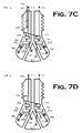
- FIG. 7 A– FIG. 7D illustrate several alternative embodiments of an instrumented bit in accordance with the present invention.
- FIG. 8 – FIG. 10 illustrate another alternative embodiment of an instrumented bit in accordance with the present invention.
- FIG. 11 conceptually illustrates a drilling operation employing the embodiment of FIG. 8 FIG. 10 down-hole in accordance with an embodiment alternative to that shown in FIG. 3 .
- FIG. 12 A– FIG. 12B depict an exemplary joint in the drill string of FIG. 11 ;
- FIG. 13 A– FIG. 13C illustrate one section of pipe, two of which are mated to form the joint of FIG. 12A FIG. 12B .
- FIG. 14 A– FIG. 14B illustrate an electromagnetic coupler of the section in FIG. 13A FIG. 13C in assembled and exploded views, respectively, that form a electromagnetic coupling in the joint of FIG. 12A FIG. 12B .
- FIG. 15 illustrates a drilling operation in which the present invention is used in a directional drilling application, as opposed to the vertical drilling applications of FIG. 3 and FIG. 11 .
- FIG. 1 conceptually illustrates an instrumented bit 100 constructed in accordance with the present invention.
- the instrumented bit 100 comprises a bit 103 , a plurality of transducers 106 , and an analog multiplexer 109 .
- the transducers 106 and analog multiplexer 109 may be situated on the bit 103 in any suitable manner known to the art.
- the transducers 106 sense various conditions in the environment in which the bit 103 operates, and outputs analog electrical signals indicative of the sensed condition on the respective lines 112 .
- the analog multiplexer 109 receives the outputs of the transducers 106 over the lines 112 , multiplexes them, and transmits the multiplexed outputs over the line 115 .
- the analog multiplexer 109 is capable of receiving the output of the transducers 106 , multiplexing the received outputs, and transmitting the multiplexed outputs.
- the bit 103 may be any conventional bit known to the art.
- the bit 103 may be a roller cone bit or a fixed cutter bit.
- the bit 103 includes a thread 118 by which the bit 103 may be joined to sections of drill pipe, subs, or tools (none of which are shown in FIG. 1 ) to comprise a portion of a drill string.
- the bit 103 defines a channel 121 extending therethrough and through which drilling fluids may be pumped in accordance with standard practices known to the art.
- the bit 103 also defines, in this particular embodiment, a plurality of “pockets” 124 in which the transducers 106 are situated in accordance with conventional practice.
- the transducers 106 sense various conditions in the environment in which the bit 103 operates. These conditions may be, for example, associated with temperature, pressure, direction, stress, etc. The conditions of interest will be known to those in the art having the benefit of this disclosure and will be implementation specific. Thus, various alternative embodiments may employ different types of sensors. Exemplary types of sensors that may be employed in various embodiments include, but are not limited to, temperature transducers, strain gauges, accelerometers, pressure transducers, and directional transducers. In one particular embodiment, at least one of the transducers 106 is a wear sensor, which is not known to the art but is disclosed in co-pending U.S. Provisional Application Ser. No. 60/521,299, entitled “Wear Sensor”, and filed on Mar.
- some embodiments may employ a set of transducers 106 that are all of the same type, while others may “mix-and-match”different types of transducers 106 .
- the number and position of the transducers 106 will depend on the conditions to be sensed. Temperature sensors may be employed in different numbers and different locations from pressure sensors, for instance. The considerations as to number and placement of the transducers 106 as a function of the conditions they sense are well known in the art. Selection, number, and placement of the transducers 106 is therefore not material to the present invention, although they may be concerns in implementing individual embodiments. However, since these matters are well within the ordinary skill of the art, they are not further discussed so as to avoid obscuring the present invention.
- the analog multiplexer 109 receives the outputs of the transducers 106 over the lines 112 , multiplexes them, and transmits the multiplexed outputs uphole over the line 115 .
- the analog multiplexer 109 should be sufficiently rugged to withstand the rigors of operating in the relatively harsh environments encountered down-hole during drilling. Some commercially available, off-the-shelf analog multiplexers are available. One such analog multiplexer is the LTC1390, commercially available from:Linear Technology, Inc.
- the present invention effectively reduces the number of leads, and therefore the number of connections, needed to carry the information to, for instance, the surface.
- the analog multiplexer 109 multiplexes the outputs of three transducers 106 onto the single line 115 .
- the illustrated embodiment therefore uses only a single conductor (i.e., the line 115 ) to transport data from multiple data sources (i.e., the transducers 106 ) to, for example, a subassembly (not shown) above the bit and, eventually, the surface.
- the illustrated embodiment realizes a three to one reduction in the number of lines and connections, although the scale of the reduction will be implementation specific.
- the transducers 106 and the analog multiplexer 109 are wired together, as shown in FIG. 2 , into an on-bit electrical circuit 200 .
- Techniques for wiring electrical circuits on-bit are known to the art, and such techniques may be used to wire the circuit 200 .
- the circuit 200 includes a clock signal 203 , a power (V+) signal 206 , and a power (GND) signal 209 not shown in FIG. 1 .
- These signals may be provided on-bit in a manner described more fully below, or may be transmitted directly to the instrumented bit 100 , shown in FIG. 1 , through the drill string (not shown). For instance, these signals may be transmitted to the instrumented bit 100 over the lines 127 .
- the analog multiplexer 109 changes state on the falling edge (not shown) of the clock signal 203 .
- the analog multiplexer 109 and, hence, the circuit 200 transmits the data 212 up hole to the rest of the drill string (not shown).
- FIG. 3 illustrates the instrumented bit 100 of FIG. 1 assembled into a drill string 300 .
- the drill string 300 is suspended in a bore 303 in the ground 306 from equipment (not shown) aboard a drilling rig 309 .
- the drill string 300 comprises, in addition to the instrumented bit 100 , a plurality of sections 3120 312 x , which may be variety of drill pipe sections, subassemblies, tools, etc. as are commonly known and used in the art.
- the section 312 x in this particular embodiment, is a down-hole tool designed to connect to the instrumented bit 100 in accordance with the present invention.
- the section 312 x includes, as is shown in FIG. 4 , a circuit 400 .
- the circuit 400 comprises a battery pack 403 generating the power (V+) and power (GND) signals 206 , 209 and a clock circuit 406 generating the clock signal 203 , the signals 203 , 206 , 209 being provided to the circuit 200 , shown in FIG. 2 , as described above.
- the power from the battery pack 403 passes through a DC/DC converter 409 to step the voltage down from that produced by the battery pack 403 to that consumed by the components of the circuit 200 .
- Analog data from the instrumented bit 100 is converted to digital by the analog-to-digital (“A/D”) converter 412 , processed by the field programmable gate array (“FPGA”) 415 , and stored in the flash memory 418 .
- A/D analog-to-digital
- FPGA field programmable gate array
- the circuit 400 admits variation in its implementation.
- the FPGA 415 could be replaced with, for example, a digital signal processor (“DSP”) and the flash memory 418 may be replaced by some other kind of storage.
- DSP digital signal processor
- the sampling rate for the multiplexer 109 is chosen according to the desired frequency content to be retained in the data, and the sampling is carried out by the multiplexer 109 driven by a CLOCK timing signal 203 .
- the multiplexer 109 samples an analog channel from one of the transducers 106 on one of its inputs 215 .
- the data sampled on the inputs 215 is combined into a serial stream and presented at the output 218 of the multiplexer 109 .
- the serial stream of data produced on the multiplexer output 218 is then transmitted up the bit 103 and into the drill string 300 , shown in FIG. 3 , via a single conductor.
- an analog de-multiplexer (not shown) of the same type may be implemented within the drill string 300 to split the data back out into parallel.
- the data 212 is either stored down-hole until the drill string 300 is tripped to the surface 315 , or it is transmitted to the surface 315 during drilling operations.
- the data is stored down-hole. If transmitted to the surface 315 , the data 212 will typically be transmitted to a computing apparatus 318 .
- the computing apparatus 318 may store the data 212 and/or analyze it to determine whether it is desirable to change drilling conditions to meet drilling goals. Such an analysis may be performed contemporaneously or at some later time. If the data 212 is stored, it can be archived. In some embodiments, the data 212 may even be transported offsite, whether by satellite communication, transmission over a network connection (to, e.g., the Internet), or transport on a storage medium (e.g., a floppy disk).
- a network connection to, e.g., the Internet
- a storage medium e.g., a floppy disk
- the present invention provides an instrumented bit (e.g., the instrumented bit 100 , of FIG. 1 ) in which the circuit designer can cut out a whole analog-to-digital conversion stage by not converting the analog waveform to digital format prior to multiplexing. This will result in fewer wire traces and fewer chips needed, thereby reducing the overall footprint of the circuit design.
- the emphasis is to save critical design space by keeping as much circuitry away from the cutting structure of the bit and more concentrated in the bit body, and analog multiplexers allow this to a greater degree than do digital multiplexers.
- the analog multiplexed signal can also be run through an analog-to-digital (“A/D”) converter before being transmitted from the bit.
- A/D analog-to-digital
- Some embodiments may also choose to filter prior to A/D conversion to help suppress noise.
- An integrated filter and A/D converter may be used without significant increase in space relative to an A/D converter.
- the present invention admits some degree of variation in implementation.
- the instrumented bit 500 differs from the instrumented bit 110 , shown in FIG. 1 , in at least three ways.
- the instrumented bit 500 employs a sufficient number of transducers 503 distributed about the bit 506 that a plurality of multiplexers 509 are employed. Although this doubles the number of lines 512 on which the multiplexers 509 output data, it still reduces the number of lines on which the data would otherwise be sent up hole by a factor of three to one.
- the instrumented bit 500 includes some power and timing circuitry 515 , which is now on-bit, as opposed to in an up hole tool.
- the instrumented bit 500 includes a plurality of filters 521 to mitigate aliasing effects that may arise from the multiplexer sampling process.
- transducers 503 will not need filters because the sampling by the multiplexers 509 will not introduce aliasing effects in their output. For instance, the output of temperature sensors, accelerometers, and wear sensors may not need to be filtered. Furthermore, some types of sensors whose output may need filtering may include such filters a priori, thereby eliminating the need for additional filters such as the filters 521 . Conversely, filters 521 may be employed even where not necessarily technically desirable to reduce such aliasing effects. Thus, the inclusion of the filters 521 to prevent aliasing effects will be implementation specific. However, the absence of filters such as the filters 521 will increase the likelihood of data corruption resulting from noise. Data processing techniques are known to the art and are available for reducing data corruption from sources such as noise.
- filters 521 can be implemented using simple RC (“resistance-capacitance”) circuits.
- the bit 506 might have eight sensors installed in pockets (not shown) machined within the body of the bit.
- the bit 506 is a roller-cone bit, although the present invention can be used for both fixed-cutter and roller-cone bits.
- the transducers 503 can then be:
- each transducer 503 is fed into an analog, anti-aliasing filter 521 and then, in this particular implementation, into an amplification stage (not shown) that adds gain and offset to the sensor output signal to match the input voltage range of the multiplexer 509 .
- the separate data signals 606 are then fed into an analog multiplexer 509 , which successively samples these data lines with minimum time delay introduced.
- the filters 521 can be implemented using a simple RC circuit with a designed time constant that depends on overall desired frequency content to be retained in the data. Filtering prevents aliasing effects from occurring during the multiplexer sampling process and also to reduce unwanted noise. For example, to retain frequencies less than 400 Hz, the antialiasing filters 521 can be safely designed to have a 3 dB cutoff at 1 kHz.
- the multiplexer sampling rate also satisfies the Nyquist rate.
- the sampling rate exceeds 800 Hz.
- the sampling is performed the multiplexer 509 driven by a CLOCK timing signal 203 with a frequency greater than 800 Hz.
- the commercially available, eight-channel LTC1390 multiplexer mentioned above, can be clocked at this frequency by a timing signal produced by a small crystal oscillator mounted either on the bit 506 or on a subassembly above the instrumented bit 500 (e.g., the section 312 x ), depending on whether a down-hole tool is present.
- the multiplexers 509 sample an analog channel on one of its inputs 603 .
- the data sampled on the inputs 603 is concatenated into a serial stream and presented at the outputs 609 of the multiplexers 509 .
- the serial stream of data produced on each multiplexer output 609 is then transmitted through the bit 506 via a single conductor.
- the instrumented bit 500 of FIG. 5 includes eight transducers 503 and two multiplexers 509 .
- Each of the multiplexers 509 is, in the illustrated embodiment, a four-channel multiplexer.
- the multiplexers 509 can be implemented with a commercially available, eight-channel multiplexer.
- one of the multiplexers 509 can be eliminated by multiplexing the outputs 603 , shown in FIG. 6 , of all eight transducers 503 with the remaining multiplexer 509 .
- the outputs of the multiplexers 509 may be also be multiplexed. FIG.
- FIG. 7A illustrates one such embodiment wherein the outputs 609 of the multiplexers 509 in an instrumented bit 700 a are input to another multiplexer 703 , multiplexed, and output so that the data is transmitted up hole on only a single line 706 .
- the A/D capability is performed by the A/D converter 412 , shown in FIG. 4 , of the section 312 x , shown in FIG. 3 , of the drill string 300 .
- the A/D capability may be mounted on-bit.
- FIG. 7B depicts an instrumented bit 700 b , which substitutes integrated A/D converters and multiplexers 709 for the multiplexers 509 of the instrumented bit 500 in FIG. 5 .
- the A/D converters perform the A/D conversion after the transducer outputs are multiplexed.
- the data stream on the lines 712 is digital, rather than analog.
- this data stream can be either transmitted into the drill string via very few conductors to a down-hole tool above the bit (i.e., a memory-mode tool) or across the pipe connection using inductive coils coupled together in close proximity (i.e., real-time transmission via intelligent drill pipe).
- a down-hole tool above the bit i.e., a memory-mode tool
- inductive coils coupled together in close proximity i.e., real-time transmission via intelligent drill pipe.
- Some alternative embodiments may also employ standalone power and timing circuitry that does not receive power from a source off the bit.
- One such embodiment 700 d is shown in FIG. 7D .
- the power source i.e., batteries
- the instrumented bit 700 d eliminates the need for the wire 518 in FIG. 5 altogether, and further reduces the number of leads and electrical connections between the instrumented bit 700 d and the rest of the drill string.
- FIG. 8 FIG. 9 illustrate an instrumented bit 800 and the electronic circuit 900 thereon, respectively.
- the instrumented bit 800 includes a plurality of transducers 803 whose outputs are filtered by the filters 821 and multiplexed by the multiplexer 809 for transmission uphole, as was discussed above for other embodiments.
- the on-bit power and timing circuit 815 provides power and timing signals to the transducers 803 , filters 821 , and multiplexer 809 , also in the manner discussed above for other embodiments. Note that, in this particular embodiment, the filtered outputs of all eight of the transducers 803 are multiplexed by the single multiplexer 809 .
- the instrumented bit 800 is intended for use in a drill string employing “intelligent”, or “wired”, drill pipe.
- the instrumented bit 800 therefore also includes transmission circuitry 824 that conditions the multiplexed data for transmission uphole.
- the transmission circuitry 824 is better illustrated in FIG. 10 , and includes an A/D converter 1003 , a micro-controller 1006 , a digital modem 1009 , and an analog switch 1012 .
- Power signals POWER (V+) 206 and POWER (GND) 209 from the power and timing circuit 815 power these components through a linear regulator 1015 .
- the analog multiplexed data 212 is received over the line 1018 and converted to digital by the A/D converter 1003 .
- the microcontroller 1006 communicates with other down-hole acquisition systems (not shown) present in the drill string via RS232 interface. It receives and processes data received through the digital modem 1009 and from the instrumented bit 800 , i.e., the data digitized by the A/D converter 1003 . With respect to the digitized data, the microcontroller 1006 formats the outgoing data for transmission along the wired drill pipe (i.e., adds start/stop bits, checksum, etc).
- the digital modem 1006 modulates the digital data, transmitted in packets, for transmission uphole in light of the inductive mechanism, illustrated in FIG. 12A FIG. 14B , and discussed further below, used in implementing the transmission path.
- the analog switch 1012 routes the digital, modulated data up the wired drill string. Note, however, that if the transmission circuitry were moved off-bit, the analog switch 1012 would be responsible for routing signals both up and down the drill string.
- the signals might include, in addition to the modulated digital data originating from the transducers 803 , shown in FIG. 8 , data from sensors up and down the drill string. These signals might also include command and control signals to the instrumented bit 800 or other instrumented tools in the drill string.
- FIG. 11 schematically illustrates a drilling operation 1100 employing the instrumented bit 800 , best shown in FIG. 8 , comprising a portion of the drill string 1103 .
- a drill string 1103 including the instrumented bit 800 , is drilling a borehole 1104 in the ground 1105 beneath the surface 1107 thereof.
- the drill string 1103 implements a “down-hole local area network,” or “DLAN”.
- the drilling operation 1100 includes a rig 1106 from which the drill string 1103 is suspended through a kelly 1109 .
- a data transceiver 1112 is fitted on top of the kelly 1109 , which is, in turn, connected to a drill string 1103 comprised of a plurality of sections of drill pipe 1115 (only one indicated).
- tools such as jars and stabilizers.
- Drill collars also not indicated
- heavyweight drill pipe 1118 are located near the bottom of the drill string 1103 .
- a data and crossover sub 1121 is included just above the instrumented bit 800 .
- the drill string 1103 interfaces with a computing apparatus 1124 through the kelly 1109 by means of a swivel, such as is known in the art.
- the drill string 1103 will include a variety of instrumented tools for gathering information regarding down-hole drilling conditions.
- the instrumented bit 800 is connected to a data and crossover sub 1121 housing a sensor apparatus 1124 including an accelerometer (not shown).
- the accelerometer is useful for gathering real time data from the bottom of the hole.
- the accelerometer can give a quantitative measure of bit vibration.
- the data and crossover sub 1121 includes a transmission path such as that described below for the sections 1300 in FIG. 13A FIG. 13C . So, too, do the instrumented bit 800 and the heavyweight drill pipe 1118 .
- Exemplary measurements that may be of interest include hole temperature and pressure, salinity and pH of the drilling mud, magnetic declination and horizontal declination of the bottom-hole assembly, seismic look-ahead information about the surrounding formation, electrical resistivity of the formation, pore pressure of the formation, gamma ray characterization of the formation, and so forth.
- the drill string 1103 will transmit data at a rate of at least 100 bits/second, and on up to at least 1,000,000 bits/second.
- signal attenuation is a concern.
- a typical length for a section of pipe e.g., the section 1300 in FIG. 13A
- Drill strings in oil and gas production can extend as long as 20,000′′ 30,000′′, or longer, which means that as many as 700 sections of drill pipe, down hole tools, collars, subs, etc. can found in a drill string such as the drill string 1103 .
- the transmission line created through the drill string by the pipe described above will typically transmit the information signal a distance of 1,000 to 2,000 feet before the signal is attenuated to the point where amplification will be desirable.
- amplifiers, or “repeaters,” 1130 are provided for approximately for some of the components in the drill string 1103 , for example, 5% of components not to exceed 10%, in the illustrated embodiment.
- Such repeaters can be simple “dumb” repeaters that only increase the amplitude of the signal without any other modification. A simple amplifier, however, will also amplify any noise in the signal.
- a “smart” repeater that detects any errors in the data stream and restores the signal, error free, while eliminating baseline noise, is preferred. Any of a number of known digital error correction schemes can be employed in a down-hole network incorporating a “smart” repeater.
- the drill string 1103 comprises “wired pipe” that is, it includes a transmission path (not shown, but discussed further below) down its length.
- the present invention contemplates wide variation in the implementation of the transmission path under test.
- the transmission path of the illustrated embodiment, and reasonable variations thereon, are more fully disclosed and claimed in U.S. Pat. No. 6,670,880, entitled “Downhole Data Transmission System,”and issued Dec. 30, 2003, in the name of the inventors David R. Hall, et al.
- the joints 1200 (not all indicated) between these sections of the drill string 1103 comprise joints such as the joint 1200 best shown in FIG. 12A FIG. 12B .
- FIG. 12A is an enlarged view of the made up joint 1200 of FIG. 1 .
- the two individual sections 1300 are best shown in FIG. 13A FIG. 13C .
- FIG. 12B is an enlarged view of a portion 1203 of view in FIG. 12A of the joint 1200 .
- FIG. 13B FIG. 13C are enlarged views of a portion 1302 of a box end 1309 and a portion 1304 of the pin end 1306 of the section 1300 as shown in FIG. 13A .
- each section 1300 includes a transmission path that, when the two sections 1300 are mated as shown in FIG. 12A , aligns.
- the two transmission paths electromagnetically couple across the joint 1200 to create a single transmission path through the drill string 1103 .
- the present invention is directed to testing the electromagnetic connectivity across joints in a drill string such as the joint 1200 and, hence, the transmission path in the drill string 1103 .
- Various aspects of the particular transmission path of the illustrated embodiment are more particularly disclosed and claimed in the aforementioned U.S. Pat. No. 6,670,880. Pertinent portions of that patent are excerpted below.
- the present invention may be employed with other types of drill pipe and transmission systems.
- each section 1300 includes a tube body 1303 welded to an externally threaded pin end 1306 and an internally threaded box end 1309 .
- Pin and box end designs for sections of drill pipe are well known to the art, and any suitable design may be used. Acceptable designs include those disclosed and claimed in:
- Grooves 1312 , 1315 are provided in the respective tool joint 1200 as a means for housing electromagnetic couplers 1316 , each comprising a pair of toroidal cores 1318 , 1321 having magnetic permeability about which a radial or Archimedean coil (not shown) is wound.
- the groove 1315 is recessed into the secondary shoulder, or face, 1342 of the pin end 1306 .
- the groove 1312 is recessed into the internal shoulder 1345 . Additional information regarding the pin and box ends 1306 , 1309 , their manufacture, and placement is disclosed in the aforementioned U.S. Pat. No. 6,670,880.
- the grooves 1315 , 1312 are located so as to lie equidistant between the inner and outer diameter of the face 1342 and the shoulder 1345 . Further, in this orientation, the grooves 1315 , 1312 are located so as to be substantially aligned as the joint 1200 is made up.
- FIG. 14 A– FIG. 14B illustrate an electromagnetic coupler 1316 in assembled and exploded views, respectively. Additional information regarding the construction and operation of the electromagnetic coupler 1316 in various alternative embodiments are disclosed in the aforementioned U.S. Pat. No. 6,670,880.
- the electromagnetic coupler 1316 consists of an Archimedean coil, or planar, radially wound, annular coil 1403 , inserted into a core 1406 .
- the laminated and tape wound, or solid, core 1406 may be a metal or metal tape material having magnetic permeability, such as ferromagnetic materials, irons, powdered irons, ferrites, or composite ceramics, or a combination thereof.
- the core material may even be a material without magnetic permeability such as a polymer, like polyvinyl chloride (“PVC”). More particularly, in the illustrated embodiment, the core 1406 comprises a magnetically conducting, electrically insulating (“MCEI”) element.
- MCEI magnetically conducting, electrically insulating
- the annular coils 1403 may also be wound axially within the core material and may consist of one or more than one layers of coils 1403 .
- the core 1406 includes a U-shaped trough 1409 .
- the dimensions of the core 1406 and the trough 1409 can be varied based on the following factors. First, the 1406 must be sized to fit within the grooves 1312 , 1315 . In addition, the height and width of the trough 1409 should be selected to optimize the magnetically conducting properties of the core 1406 . Lying within the trough 1409 of the core 1406 is an electrically conductive coil 1403 .
- This coil 1403 comprises at least one loop of an insulated wire (not otherwise shown), typically only a single loop. The wire may be copper and insulated with varnish, enamel, or a polymer.
- a tough, flexible polymer such as high density polyethylene or polymerized tetrafluoroethane (“PTFE”) is particularly suitable for an insulator.
- PTFE polymerized tetrafluoroethane
- the coil 1403 is preferably embedded within a material (not shown) filling the trough 1409 of the core 1406 .
- the material should be electrically insulating and resilient, the resilience adding further toughness to the core 1406 .
- the core 1406 is, in turn, embedding in a material (not shown) filling the groove 1312 or 1315 . This second embedment material holds the core 1406 in place and forms a transition layer between the core 1406 and the steel of the pipe to protect the core 1406 from some of the forces seen by the steel during joint makeup and drilling.
- This resilient, embedment material may be a flexible polymer, such as a two-part, heat-curable, aircraft grade urethane. Voids or air pockets should also be avoided in this second embedment material, e.g., by centrifuging at between 2500 to 5000 rpm for about 0.5 to 3 minutes.
- a rounded groove 1324 is formed within the bore wall for conveying an insulated conductor means 1348 along the section 1300 .
- the conductor means 1348 is attached within the groove 1324 and shielded from the abrasive drilling fluid.
- the conductor means 1348 may consist of wire strands or a coaxial cable.
- the conductor means 1348 is mechanically attached to each of the toroidal cores 1318 , 1321 in a manner not shown.
- the electromagnetic couplers 1316 When installed into the grooves 1312 , 1315 , the electromagnetic couplers 1316 are potted in with an abrasion resistant material in order to protect them from drilling fluids (not shown).
- An electrical conductor 1348 is connected between the coils 1403 at the box and pin ends 1306 , 1309 of the section 1300 .
- the electrical conductor 1348 is, in the illustrated embodiment, a coaxial cable with a characteristic impedance in the range of about 30 ohm–120 ohm, e.g., in the range of about 50 ohm–75 ohm.
- the electrical conductor 1403 has a diameter of about 0.25′′ or larger.
- the conductor loop represented by the coils 1403 and the electrical conductor 1348 is completely sealed and insulated from the pipe of the section 1300 .
- the shield (not otherwise shown) should provide close to 100% coverage, and the core insulation should be made of a fully-dense polymer having low dielectric loss, e.g., from the family of polytetrafluoroethylene (“PTFE”) resins, Dupont's Teflon® being one example.
- the insulating material (not otherwise shown) surrounding the shield should have high temperature resistance, high resistance to brine and chemicals used in drilling muds.
- PTFE is again preferred, or a linear aromatic, semi-crystalline, polyetheretherketone thermoplastic polymer manufactured by Victrex PLC under the trademark PEEK ⁇ .
- the electrical conductor 1348 is also coated with, for example, a polymeric material selected from the group consisting of natural or synthetic rubbers, epoxies, or urethanes, to provide additional protection for the electrical conductor 1348 .
- the coil 1403 of the illustrated embodiment extends through the core 1406 to meet the electrical conductor 1348 at a point behind the core 1406 .
- the input leads 1412 extend through not only the core 1406 , but also holes (not shown) drilled in the grooves 1315 , 1312 through the enlarged walls of the pin end 1306 and box end 1309 , respectively, so that the holes open into the central bore 1354 of the pipe section 1300 .
- the diameter of the hole will be determined by the thickness available in the section 1300 and the input leads 1412 .
- the input leads 1412 may be sealed in the holes by, for example, urethane.
- the input leads 1412 are soldered to the electrical conductor 1348 to effect the electrical connection therebetween.
- a pin end 1306 of a first section 1300 is shown mechanically attached to the box end 1309 of a second section 1300 by means of the mating threads 1336 , 1339 .
- the sections 1300 are screwed together until the external shoulders 1330 , 1351 are compressed together forming the primary seal for the joint 1200 that prevents the loss of drilling fluid and bore pressure during drilling.
- the joint 1200 is made up, it is preloaded to approximately one half of the torsional yield strength of the pipe, itself. The preload is dependent on the wall thickness and diameter of the pipe, and may be as high as 70,000 foot-pounds.
- the grooves 1312 , 1315 should have rounded corners to reduce stress concentrations in the wall of the pipe.
- the electromagnetic coupler 1316 of the pin end 1306 and the electromagnetic coupler 1316 of the box end 1309 are brought to at least close proximity.
- the coils 1403 of the electromagnetic couplers 1316 when energized, each produces a magnetic field that is focused toward the other due to the magnetic permeability of the core material. When the coils are in close proximity, they share their magnetic fields, resulting in electromagnetic coupling across the joint 1200 . Although is not necessary for the electromagnetic couplers 1316 to contact each other for the coupling to occur, closer proximity yields a stronger coupling effect.
- the drill strong 1103 is assembled, each joint 1200 between the various sections thereof magnetically coupling to create a transmission path the length of the drill string 1103 from the instrumented bit 800 to the surface 1107 .
- the instrumented bit 800 gathers the data and transmits it uphole to the computing apparatus 1124 at the surface 1107 .
- the data may be presented to a user, analyzed, stored for later use, or some combination of these things.
- FIG. 15 illustrates a directional drilling application 1500 , in which an instrumented bit 100 , first shown in FIG. 1 FIG. 2 , comprises a portion of a drill string 1503 . Note, however, that any of the embodiments disclosed herein may be used in such an application.
- the drill string 1503 is being used to drill a bore 1506 under a water barrier 1509 , although there are many other possible directional drilling scenarios.
- the drill string 1503 aside from the instrumented bit 100 , can be implemented in any conventional fashion known to the art.
Abstract
Description
-
- three single axis accelerometers for measuring shocks (e.g., model 7290A by Endevco Corporation, 30700 Rancho Viejo Road, San Juan Capistrano, Calif. 92675, ph: 800-982-6732; fax: 949-661-7231).
- three temperature sensors for measuring bearing temperature (e.g., model RTD800 by OMEGA Engineering, Inc., One Omega Drive, Stamford, Conn. 06907-0047, P.O. Box 4047, ph: (800)-848-4286 or (203)-359-1660; fax: (203)-359-7700).
- three strain gauges for measuring strain within the bit (e.g., TK-06-S111M-10C by Vishay Intertechnology, Inc., One Greenwich Place, Shelton, Conn. 06484, United States, ph:: 1-402-563-6866; Fax: 1-402-563-6296).
-
- a filter capable of filtering the analog output of the transducers.
- a power circuit providing a power signal to at least one of the multiplexer and at least one of the transducers.
- a timing circuit capable of providing a timing signal to at least one of the multiplexer and at least one of the transducers.
- one or more additional mutliplexers.
-
- U.S. Pat. No. 5,908,212, entitled “Ultra High Torque Double Shoulder Tool Joint”, and issued Jun. 1, 1999, to Grant Prideco, Inc. of The Woodlands, Texas, as assignee of the inventors Smith, et al.
- U.S. Pat. No. 5,454,605, entitled “Tool Joint Connection with Interlocking Wedge Threads”, and issued Oct. 3, 1995, to Hydril Company of Houston, Tex., as assignee of the inventor Keith C. Mott.
-
- U.S. Pat. No. 6,670,880, entitled “Down-hole Data Transmission System,”and issued Dec. 30, 2003, in the name of the inventors David R. Hall, et al.
- U.S. Provisional Application Ser. No. 60/521,299, entitled “Wear Sensor”, and filed on Mar. 29, 2004, in the name of the inventors Marcel Boucher, et al.
Claims (33)
Priority Applications (1)
| Application Number | Priority Date | Filing Date | Title |
|---|---|---|---|
| US10/709,108 US7168506B2 (en) | 2004-04-14 | 2004-04-14 | On-bit, analog multiplexer for transmission of multi-channel drilling information |
Applications Claiming Priority (1)
| Application Number | Priority Date | Filing Date | Title |
|---|---|---|---|
| US10/709,108 US7168506B2 (en) | 2004-04-14 | 2004-04-14 | On-bit, analog multiplexer for transmission of multi-channel drilling information |
Publications (2)
| Publication Number | Publication Date |
|---|---|
| US20050230149A1 US20050230149A1 (en) | 2005-10-20 |
| US7168506B2 true US7168506B2 (en) | 2007-01-30 |
Family
ID=35095106
Family Applications (1)
| Application Number | Title | Priority Date | Filing Date |
|---|---|---|---|
| US10/709,108 Active 2024-12-27 US7168506B2 (en) | 2004-04-14 | 2004-04-14 | On-bit, analog multiplexer for transmission of multi-channel drilling information |
Country Status (1)
| Country | Link |
|---|---|
| US (1) | US7168506B2 (en) |
Cited By (30)
| Publication number | Priority date | Publication date | Assignee | Title |
|---|---|---|---|---|
| US20050285752A1 (en) * | 2004-06-28 | 2005-12-29 | Hall David R | Down hole transmission system |
| US20060256718A1 (en) * | 2005-05-16 | 2006-11-16 | Hall David R | Apparatus for Regulating Bandwidth |
| US20070272442A1 (en) * | 2005-06-07 | 2007-11-29 | Pastusek Paul E | Method and apparatus for collecting drill bit performance data |
| US20090166088A1 (en) * | 2007-12-27 | 2009-07-02 | Schlumberger Technology Corporation | Subsurface formation core acquisition system using high speed data and control telemetry |
| US20090190484A1 (en) * | 2008-01-25 | 2009-07-30 | Monte Johnson | Directional topology discovery for downhole networks |
| US20090189777A1 (en) * | 2008-01-25 | 2009-07-30 | Monte Johnson | Topology maintenance and discovery facility for downhole networks |
| US20090194332A1 (en) * | 2005-06-07 | 2009-08-06 | Pastusek Paul E | Method and apparatus for collecting drill bit performance data |
| US20100038136A1 (en) * | 2008-08-18 | 2010-02-18 | Baker Hughes Incorporated | Drill Bit With A Sensor For Estimating Rate Of Penetration And Apparatus For Using Same |
| US20100078216A1 (en) * | 2008-09-25 | 2010-04-01 | Baker Hughes Incorporated | Downhole vibration monitoring for reaming tools |
| US20100097890A1 (en) * | 2008-10-20 | 2010-04-22 | Sullivan Eric C | Methods and apparatuses for data collection and communication in drill string components |
| US20100108380A1 (en) * | 2008-11-03 | 2010-05-06 | Baker Hughes Incorporated | Methods and apparatuses for estimating drill bit cutting effectiveness |
| US20100212961A1 (en) * | 2009-02-24 | 2010-08-26 | Baker Hughes Incorporated | Methods and apparatuses for estimating drill bit condition |
| US20110186353A1 (en) * | 2010-02-01 | 2011-08-04 | Aps Technology, Inc. | System and Method for Monitoring and Controlling Underground Drilling |
| EP2352896A2 (en) | 2008-12-04 | 2011-08-10 | Baker Hughes Incorporated | Method of monitoring wear of rock bit cutters |
| US20110266058A1 (en) * | 2010-04-28 | 2011-11-03 | Baker Hughes Incorporated | PDC Sensing Element Fabrication Process and Tool |
| US20120062235A1 (en) * | 2010-09-14 | 2012-03-15 | National Oilwell DHT, L.P. | Downhole sensor assembly and method of using same |
| US20120103688A1 (en) * | 2010-10-29 | 2012-05-03 | Baker Hughes Incorporated | Drill-Bit Seismic With Downhole Sensors |
| US20120312599A1 (en) * | 2011-06-13 | 2012-12-13 | Baker Hughes Incorporated | Cutting elements comprising sensors, earth-boring tools having such sensors, and associated methods |
| US20140231142A1 (en) * | 2013-02-20 | 2014-08-21 | Schlumberger Technology Corporation | Drill bit systems with temperature sensors and applications using temperature sensor measurements |
| US9222350B2 (en) | 2011-06-21 | 2015-12-29 | Diamond Innovations, Inc. | Cutter tool insert having sensing device |
| US9593567B2 (en) | 2011-12-01 | 2017-03-14 | National Oilwell Varco, L.P. | Automated drilling system |
| US20170292376A1 (en) * | 2010-04-28 | 2017-10-12 | Baker Hughes Incorporated | Pdc sensing element fabrication process and tool |
| US10132158B2 (en) | 2014-12-19 | 2018-11-20 | Halliburton Energy Services, Inc. | Roller cone drill bit with embedded gamma ray detector |
| USD843381S1 (en) | 2013-07-15 | 2019-03-19 | Aps Technology, Inc. | Display screen or portion thereof with a graphical user interface for analyzing and presenting drilling data |
| US10233698B2 (en) | 2013-07-22 | 2019-03-19 | Schlumberger Technology Corporation | Instrumented rotary tools with attached cutters |
| US10472944B2 (en) | 2013-09-25 | 2019-11-12 | Aps Technology, Inc. | Drilling system and associated system and method for monitoring, controlling, and predicting vibration in an underground drilling operation |
| US10605004B1 (en) * | 2016-07-29 | 2020-03-31 | Rei, Inc. | Intellegent blast-hole drill bit with redundant transducer wear sensor and remote recessed reflector antenna |
| US11162350B2 (en) * | 2019-10-30 | 2021-11-02 | Halliburton Energy Services, Inc. | Earth-boring drill bit with mechanically attached strain puck |
| US11293275B2 (en) | 2018-05-04 | 2022-04-05 | Schlumberger Technology Corporation | Recording device for measuring downhole parameters |
| US11619123B2 (en) | 2019-10-30 | 2023-04-04 | Halliburton Energy Services, Inc. | Dual synchronized measurement puck for downhole forces |
Families Citing this family (15)
| Publication number | Priority date | Publication date | Assignee | Title |
|---|---|---|---|---|
| US7319410B2 (en) * | 2004-06-28 | 2008-01-15 | Intelliserv, Inc. | Downhole transmission system |
| US8210280B2 (en) * | 2008-10-13 | 2012-07-03 | Baker Hughes Incorporated | Bit based formation evaluation using a gamma ray sensor |
| US8109329B2 (en) * | 2009-01-15 | 2012-02-07 | Intelliserv, L.L.C. | Split-coil, redundant annular coupler for wired downhole telemetry |
| US8757291B2 (en) * | 2010-04-28 | 2014-06-24 | Baker Hughes Incorporated | At-bit evaluation of formation parameters and drilling parameters |
| US8261471B2 (en) * | 2010-06-30 | 2012-09-11 | Hall David R | Continuously adjusting resultant force in an excavating assembly |
| US9790785B2 (en) * | 2012-12-28 | 2017-10-17 | Halliburton Energy Services, Inc. | Systems and methods for downhole telecommunication |
| US10227656B2 (en) | 2013-11-08 | 2019-03-12 | Baylor College Of Medicine | Diagnostic/prognostic marker and therapeutic target for cancer |
| AU2014415575B2 (en) | 2014-12-31 | 2018-12-13 | Halliburton Energy Services, Inc. | Roller cone resistivity sensor |
| JP6506420B2 (en) * | 2015-02-23 | 2019-04-24 | トランスオーシャン セドコ フォレックス ベンチャーズ リミテッド | Smart load pin for drawworks |
| US11181657B2 (en) | 2015-04-20 | 2021-11-23 | National Oilwell DHT, L.P. | Wellsite sensor assembly and method of using same |
| US9464487B1 (en) * | 2015-07-22 | 2016-10-11 | William Harrison Zurn | Drill bit and cylinder body device, assemblies, systems and methods |
| US10662755B2 (en) * | 2018-02-05 | 2020-05-26 | Baker Hughes Oilfield Operations Llc | Sensors in earth-boring tools, related systems, and related methods |
| US20190352973A1 (en) * | 2018-05-15 | 2019-11-21 | Saudi Arabian Oil Company | Drill bit system |
| US11492898B2 (en) | 2019-04-18 | 2022-11-08 | Saudi Arabian Oil Company | Drilling system having wireless sensors |
| US11199082B2 (en) * | 2020-04-30 | 2021-12-14 | Halliburton Energy Services, Inc. | Sensor integrated drill bit and method of drilling employing a sensor integrated drill bit |
Citations (32)
| Publication number | Priority date | Publication date | Assignee | Title |
|---|---|---|---|---|
| US3707700A (en) | 1969-08-21 | 1972-12-26 | Schlumberger Technology Corp | Telemetry system incorporating synchromization of receiver with transmitter |
| US4001774A (en) * | 1975-01-08 | 1977-01-04 | Exxon Production Research Company | Method of transmitting signals from a drill bit to the surface |
| US4033186A (en) | 1976-08-06 | 1977-07-05 | Don Bresie | Method and apparatus for down hole pressure and temperature measurement |
| US4161782A (en) | 1977-12-23 | 1979-07-17 | Otis Engineering Corporation | Microprocessor computerized pressure/temperature/time down-hole recorder |
| US4227405A (en) | 1979-04-06 | 1980-10-14 | Century Geophysical Corporation | Digital mineral logging system |
| US4227404A (en) | 1978-04-17 | 1980-10-14 | Century Geophysical Corporation | Digital mineral logging system |
| USRE31222E (en) | 1977-12-23 | 1983-04-26 | Otis Engineering Corporation | Microprocessor computerized pressure/temperature/time .[.down-hole.]. recorder |
| US4409824A (en) | 1981-09-14 | 1983-10-18 | Conoco Inc. | Fatigue gauge for drill pipe string |
| US4415895A (en) | 1981-02-11 | 1983-11-15 | Dresser Industries, Inc. | Well logging data transmission system |
| US4434971A (en) | 1981-02-11 | 1984-03-06 | Armco Inc. | Drilling rig drawworks hook load overspeed preventing system |
| US4459760A (en) | 1982-02-24 | 1984-07-17 | Applied Technologies Associates | Apparatus and method to communicate information in a borehole |
| US4471533A (en) * | 1981-03-09 | 1984-09-18 | Applied Technologies Associates | Well mapping system and method with sensor output compensation |
| US4507735A (en) | 1982-06-21 | 1985-03-26 | Trans-Texas Energy, Inc. | Method and apparatus for monitoring and controlling well drilling parameters |
| US4527425A (en) | 1982-12-10 | 1985-07-09 | Nl Industries, Inc. | System for detecting blow out and lost circulation in a borehole |
| US4556884A (en) | 1978-10-10 | 1985-12-03 | Dresser Industries, Inc. | Depth dependent multiple logging system |
| US4578675A (en) | 1982-09-30 | 1986-03-25 | Macleod Laboratories, Inc. | Apparatus and method for logging wells while drilling |
| US4583093A (en) | 1983-08-16 | 1986-04-15 | Halliburton Company | Telemetry driving circuit |
| EP0186328A2 (en) | 1984-12-10 | 1986-07-02 | Halliburton Company | Signal processing apparatus for use in well borehole |
| US5064006A (en) | 1988-10-28 | 1991-11-12 | Magrange, Inc | Downhole combination tool |
| US5133417A (en) | 1990-06-18 | 1992-07-28 | The Charles Machine Works, Inc. | Angle sensor using thermal conductivity for a steerable boring tool |
| US5230387A (en) | 1988-10-28 | 1993-07-27 | Magrange, Inc. | Downhole combination tool |
| US5251708A (en) | 1990-04-17 | 1993-10-12 | Baker Hughes Incorporated | Modular connector for measurement-while-drilling tool |
| US5273122A (en) | 1991-02-25 | 1993-12-28 | Elf Aquitaine Production | Automatic method for monitoring the vibrational state of a drill string |
| US5278758A (en) | 1990-04-17 | 1994-01-11 | Baker Hughes Incorporated | Method and apparatus for nuclear logging using lithium detector assemblies and gamma ray stripping means |
| US5454605A (en) | 1993-06-15 | 1995-10-03 | Hydril Company | Tool joint connection with interlocking wedge threads |
| US5813480A (en) | 1995-02-16 | 1998-09-29 | Baker Hughes Incorporated | Method and apparatus for monitoring and recording of operating conditions of a downhole drill bit during drilling operations |
| US5908212A (en) | 1997-05-02 | 1999-06-01 | Grant Prideco, Inc. | Ultra high torque double shoulder tool joint |
| US6026915A (en) | 1997-10-14 | 2000-02-22 | Halliburton Energy Services, Inc. | Early evaluation system with drilling capability |
| US6230822B1 (en) | 1995-02-16 | 2001-05-15 | Baker Hughes Incorporated | Method and apparatus for monitoring and recording of the operating condition of a downhole drill bit during drilling operations |
| US6550321B1 (en) | 1997-09-18 | 2003-04-22 | Solinst Canada Limited | Apparatus for measuring and recording data from boreholes |
| US6670880B1 (en) | 2000-07-19 | 2003-12-30 | Novatek Engineering, Inc. | Downhole data transmission system |
| US6842990B2 (en) | 2002-06-20 | 2005-01-18 | Robert M. Taylor | Inclinometer system |
-
2004
- 2004-04-14 US US10/709,108 patent/US7168506B2/en active Active
Patent Citations (33)
| Publication number | Priority date | Publication date | Assignee | Title |
|---|---|---|---|---|
| US3707700A (en) | 1969-08-21 | 1972-12-26 | Schlumberger Technology Corp | Telemetry system incorporating synchromization of receiver with transmitter |
| US4001774A (en) * | 1975-01-08 | 1977-01-04 | Exxon Production Research Company | Method of transmitting signals from a drill bit to the surface |
| US4033186A (en) | 1976-08-06 | 1977-07-05 | Don Bresie | Method and apparatus for down hole pressure and temperature measurement |
| US4161782A (en) | 1977-12-23 | 1979-07-17 | Otis Engineering Corporation | Microprocessor computerized pressure/temperature/time down-hole recorder |
| USRE31222E (en) | 1977-12-23 | 1983-04-26 | Otis Engineering Corporation | Microprocessor computerized pressure/temperature/time .[.down-hole.]. recorder |
| US4227404A (en) | 1978-04-17 | 1980-10-14 | Century Geophysical Corporation | Digital mineral logging system |
| US4556884A (en) | 1978-10-10 | 1985-12-03 | Dresser Industries, Inc. | Depth dependent multiple logging system |
| US4227405A (en) | 1979-04-06 | 1980-10-14 | Century Geophysical Corporation | Digital mineral logging system |
| US4415895A (en) | 1981-02-11 | 1983-11-15 | Dresser Industries, Inc. | Well logging data transmission system |
| US4434971A (en) | 1981-02-11 | 1984-03-06 | Armco Inc. | Drilling rig drawworks hook load overspeed preventing system |
| US4471533A (en) * | 1981-03-09 | 1984-09-18 | Applied Technologies Associates | Well mapping system and method with sensor output compensation |
| US4409824A (en) | 1981-09-14 | 1983-10-18 | Conoco Inc. | Fatigue gauge for drill pipe string |
| US4459760A (en) | 1982-02-24 | 1984-07-17 | Applied Technologies Associates | Apparatus and method to communicate information in a borehole |
| US4507735A (en) | 1982-06-21 | 1985-03-26 | Trans-Texas Energy, Inc. | Method and apparatus for monitoring and controlling well drilling parameters |
| US4578675A (en) | 1982-09-30 | 1986-03-25 | Macleod Laboratories, Inc. | Apparatus and method for logging wells while drilling |
| US4527425A (en) | 1982-12-10 | 1985-07-09 | Nl Industries, Inc. | System for detecting blow out and lost circulation in a borehole |
| US4583093A (en) | 1983-08-16 | 1986-04-15 | Halliburton Company | Telemetry driving circuit |
| EP0186328A2 (en) | 1984-12-10 | 1986-07-02 | Halliburton Company | Signal processing apparatus for use in well borehole |
| US5064006A (en) | 1988-10-28 | 1991-11-12 | Magrange, Inc | Downhole combination tool |
| US5230387A (en) | 1988-10-28 | 1993-07-27 | Magrange, Inc. | Downhole combination tool |
| US5251708A (en) | 1990-04-17 | 1993-10-12 | Baker Hughes Incorporated | Modular connector for measurement-while-drilling tool |
| US5278758A (en) | 1990-04-17 | 1994-01-11 | Baker Hughes Incorporated | Method and apparatus for nuclear logging using lithium detector assemblies and gamma ray stripping means |
| US5133417A (en) | 1990-06-18 | 1992-07-28 | The Charles Machine Works, Inc. | Angle sensor using thermal conductivity for a steerable boring tool |
| US5273122A (en) | 1991-02-25 | 1993-12-28 | Elf Aquitaine Production | Automatic method for monitoring the vibrational state of a drill string |
| US5454605A (en) | 1993-06-15 | 1995-10-03 | Hydril Company | Tool joint connection with interlocking wedge threads |
| US5813480A (en) | 1995-02-16 | 1998-09-29 | Baker Hughes Incorporated | Method and apparatus for monitoring and recording of operating conditions of a downhole drill bit during drilling operations |
| US6230822B1 (en) | 1995-02-16 | 2001-05-15 | Baker Hughes Incorporated | Method and apparatus for monitoring and recording of the operating condition of a downhole drill bit during drilling operations |
| US6626251B1 (en) | 1995-02-16 | 2003-09-30 | Baker Hughes Incorporated | Method and apparatus for monitoring and recording of the operating condition of a downhole drill bit during drilling operations |
| US5908212A (en) | 1997-05-02 | 1999-06-01 | Grant Prideco, Inc. | Ultra high torque double shoulder tool joint |
| US6550321B1 (en) | 1997-09-18 | 2003-04-22 | Solinst Canada Limited | Apparatus for measuring and recording data from boreholes |
| US6026915A (en) | 1997-10-14 | 2000-02-22 | Halliburton Energy Services, Inc. | Early evaluation system with drilling capability |
| US6670880B1 (en) | 2000-07-19 | 2003-12-30 | Novatek Engineering, Inc. | Downhole data transmission system |
| US6842990B2 (en) | 2002-06-20 | 2005-01-18 | Robert M. Taylor | Inclinometer system |
Cited By (60)
| Publication number | Priority date | Publication date | Assignee | Title |
|---|---|---|---|---|
| US7248177B2 (en) * | 2004-06-28 | 2007-07-24 | Intelliserv, Inc. | Down hole transmission system |
| US20050285752A1 (en) * | 2004-06-28 | 2005-12-29 | Hall David R | Down hole transmission system |
| US20060256718A1 (en) * | 2005-05-16 | 2006-11-16 | Hall David R | Apparatus for Regulating Bandwidth |
| US8100196B2 (en) | 2005-06-07 | 2012-01-24 | Baker Hughes Incorporated | Method and apparatus for collecting drill bit performance data |
| US20070272442A1 (en) * | 2005-06-07 | 2007-11-29 | Pastusek Paul E | Method and apparatus for collecting drill bit performance data |
| US20110024192A1 (en) * | 2005-06-07 | 2011-02-03 | Baker Hughes Incorporated | Method and apparatus for collecting drill bit performance data |
| US7849934B2 (en) | 2005-06-07 | 2010-12-14 | Baker Hughes Incorporated | Method and apparatus for collecting drill bit performance data |
| US20090194332A1 (en) * | 2005-06-07 | 2009-08-06 | Pastusek Paul E | Method and apparatus for collecting drill bit performance data |
| US7987925B2 (en) | 2005-06-07 | 2011-08-02 | Baker Hughes Incorporated | Method and apparatus for collecting drill bit performance data |
| US20090166088A1 (en) * | 2007-12-27 | 2009-07-02 | Schlumberger Technology Corporation | Subsurface formation core acquisition system using high speed data and control telemetry |
| US7913775B2 (en) | 2007-12-27 | 2011-03-29 | Schlumberger Technology Corporation | Subsurface formation core acquisition system using high speed data and control telemetry |
| US20090189777A1 (en) * | 2008-01-25 | 2009-07-30 | Monte Johnson | Topology maintenance and discovery facility for downhole networks |
| US7668117B2 (en) * | 2008-01-25 | 2010-02-23 | Intelliserv, Inc. | Topology maintenance and discovery facility for downhole networks |
| US7668118B2 (en) * | 2008-01-25 | 2010-02-23 | Intelliserv, Inc. | Directional topology discovery for downhole networks |
| US20090190484A1 (en) * | 2008-01-25 | 2009-07-30 | Monte Johnson | Directional topology discovery for downhole networks |
| US20100038136A1 (en) * | 2008-08-18 | 2010-02-18 | Baker Hughes Incorporated | Drill Bit With A Sensor For Estimating Rate Of Penetration And Apparatus For Using Same |
| US7946357B2 (en) * | 2008-08-18 | 2011-05-24 | Baker Hughes Incorporated | Drill bit with a sensor for estimating rate of penetration and apparatus for using same |
| US20100078216A1 (en) * | 2008-09-25 | 2010-04-01 | Baker Hughes Incorporated | Downhole vibration monitoring for reaming tools |
| US8164980B2 (en) | 2008-10-20 | 2012-04-24 | Baker Hughes Incorporated | Methods and apparatuses for data collection and communication in drill string components |
| US20100097890A1 (en) * | 2008-10-20 | 2010-04-22 | Sullivan Eric C | Methods and apparatuses for data collection and communication in drill string components |
| US20100108380A1 (en) * | 2008-11-03 | 2010-05-06 | Baker Hughes Incorporated | Methods and apparatuses for estimating drill bit cutting effectiveness |
| US8016050B2 (en) | 2008-11-03 | 2011-09-13 | Baker Hughes Incorporated | Methods and apparatuses for estimating drill bit cutting effectiveness |
| EP2352896A4 (en) * | 2008-12-04 | 2014-05-07 | Baker Hughes Inc | Method of monitoring wear of rock bit cutters |
| EP2352896A2 (en) | 2008-12-04 | 2011-08-10 | Baker Hughes Incorporated | Method of monitoring wear of rock bit cutters |
| WO2010099073A1 (en) * | 2009-02-24 | 2010-09-02 | Baker Hughes Incorporated | Methods and apparatuses for estimating drill bit condition |
| US20100212961A1 (en) * | 2009-02-24 | 2010-08-26 | Baker Hughes Incorporated | Methods and apparatuses for estimating drill bit condition |
| US8028764B2 (en) | 2009-02-24 | 2011-10-04 | Baker Hughes Incorporated | Methods and apparatuses for estimating drill bit condition |
| RU2524237C2 (en) * | 2009-02-24 | 2014-07-27 | Бейкер Хьюз Инкорпорейтед | Method and device for evaluation of drill bit conditions |
| US10416024B2 (en) | 2010-02-01 | 2019-09-17 | Aps Technology, Inc. | System and method for monitoring and controlling underground drilling |
| US9696198B2 (en) | 2010-02-01 | 2017-07-04 | Aps Technology, Inc. | System and method for monitoring and controlling underground drilling |
| US8684108B2 (en) | 2010-02-01 | 2014-04-01 | Aps Technology, Inc. | System and method for monitoring and controlling underground drilling |
| US8453764B2 (en) | 2010-02-01 | 2013-06-04 | Aps Technology, Inc. | System and method for monitoring and controlling underground drilling |
| US20110186353A1 (en) * | 2010-02-01 | 2011-08-04 | Aps Technology, Inc. | System and Method for Monitoring and Controlling Underground Drilling |
| US8640791B2 (en) | 2010-02-01 | 2014-02-04 | Aps Technology, Inc. | System and method for monitoring and controlling underground drilling |
| US9695683B2 (en) | 2010-04-28 | 2017-07-04 | Baker Hughes Incorporated | PDC sensing element fabrication process and tool |
| US10662769B2 (en) * | 2010-04-28 | 2020-05-26 | Baker Hughes, A Ge Company, Llc | PDC sensing element fabrication process and tool |
| US8695729B2 (en) * | 2010-04-28 | 2014-04-15 | Baker Hughes Incorporated | PDC sensing element fabrication process and tool |
| US20110266058A1 (en) * | 2010-04-28 | 2011-11-03 | Baker Hughes Incorporated | PDC Sensing Element Fabrication Process and Tool |
| US20170292376A1 (en) * | 2010-04-28 | 2017-10-12 | Baker Hughes Incorporated | Pdc sensing element fabrication process and tool |
| US8487626B2 (en) * | 2010-09-14 | 2013-07-16 | National Oilwell Dht, Lp | Downhole sensor assembly and method of using same |
| US20120062235A1 (en) * | 2010-09-14 | 2012-03-15 | National Oilwell DHT, L.P. | Downhole sensor assembly and method of using same |
| US8800685B2 (en) * | 2010-10-29 | 2014-08-12 | Baker Hughes Incorporated | Drill-bit seismic with downhole sensors |
| US20120103688A1 (en) * | 2010-10-29 | 2012-05-03 | Baker Hughes Incorporated | Drill-Bit Seismic With Downhole Sensors |
| US9739093B2 (en) | 2011-06-13 | 2017-08-22 | Baker Hughes, A Ge Company, Llc | Cutting elements comprising sensors, earth-boring tools having such sensors, and associated methods |
| US20120312599A1 (en) * | 2011-06-13 | 2012-12-13 | Baker Hughes Incorporated | Cutting elements comprising sensors, earth-boring tools having such sensors, and associated methods |
| US9145741B2 (en) * | 2011-06-13 | 2015-09-29 | Baker Hughes Incorporated | Cutting elements comprising sensors, earth-boring tools having such sensors, and associated methods |
| US9222350B2 (en) | 2011-06-21 | 2015-12-29 | Diamond Innovations, Inc. | Cutter tool insert having sensing device |
| US9593567B2 (en) | 2011-12-01 | 2017-03-14 | National Oilwell Varco, L.P. | Automated drilling system |
| US20140231142A1 (en) * | 2013-02-20 | 2014-08-21 | Schlumberger Technology Corporation | Drill bit systems with temperature sensors and applications using temperature sensor measurements |
| US9297251B2 (en) * | 2013-02-20 | 2016-03-29 | Schlumberger Technology Corporation | Drill bit systems with temperature sensors and applications using temperature sensor measurements |
| USD928195S1 (en) | 2013-07-15 | 2021-08-17 | Aps Technology, Inc. | Display screen or portion thereof with a graphical user interface for analyzing and presenting drilling data |
| USD843381S1 (en) | 2013-07-15 | 2019-03-19 | Aps Technology, Inc. | Display screen or portion thereof with a graphical user interface for analyzing and presenting drilling data |
| US11078772B2 (en) | 2013-07-15 | 2021-08-03 | Aps Technology, Inc. | Drilling system for monitoring and displaying drilling parameters for a drilling operation of a drilling system |
| US10233698B2 (en) | 2013-07-22 | 2019-03-19 | Schlumberger Technology Corporation | Instrumented rotary tools with attached cutters |
| US10472944B2 (en) | 2013-09-25 | 2019-11-12 | Aps Technology, Inc. | Drilling system and associated system and method for monitoring, controlling, and predicting vibration in an underground drilling operation |
| US10132158B2 (en) | 2014-12-19 | 2018-11-20 | Halliburton Energy Services, Inc. | Roller cone drill bit with embedded gamma ray detector |
| US10605004B1 (en) * | 2016-07-29 | 2020-03-31 | Rei, Inc. | Intellegent blast-hole drill bit with redundant transducer wear sensor and remote recessed reflector antenna |
| US11293275B2 (en) | 2018-05-04 | 2022-04-05 | Schlumberger Technology Corporation | Recording device for measuring downhole parameters |
| US11162350B2 (en) * | 2019-10-30 | 2021-11-02 | Halliburton Energy Services, Inc. | Earth-boring drill bit with mechanically attached strain puck |
| US11619123B2 (en) | 2019-10-30 | 2023-04-04 | Halliburton Energy Services, Inc. | Dual synchronized measurement puck for downhole forces |
Also Published As
| Publication number | Publication date |
|---|---|
| US20050230149A1 (en) | 2005-10-20 |
Similar Documents
| Publication | Publication Date | Title |
|---|---|---|
| US7168506B2 (en) | On-bit, analog multiplexer for transmission of multi-channel drilling information | |
| US20050212530A1 (en) | Method and Apparatus for Testing Electromagnetic Connectivity in a Drill String | |
| CA2411566C (en) | Modified tubular equipped with a tilted or transverse magnetic dipole for downhole logging | |
| US7207396B2 (en) | Method and apparatus of assessing down-hole drilling conditions | |
| EP0274457B1 (en) | Method and system for well bore data transmission | |
| US7839148B2 (en) | Method and system for calibrating downhole tools for drift | |
| US4914433A (en) | Conductor system for well bore data transmission | |
| US6885308B2 (en) | Logging while tripping with a modified tubular | |
| US8733431B2 (en) | Method and system of transmitting electromagnetic waves from a wellbore | |
| US9634473B2 (en) | Redundant wired pipe-in-pipe telemetry system | |
| US20120126992A1 (en) | Exploitation Of Sea Floor Rig Structures To Enhance Measurement While Drilling Telemetry Data | |
| CN108291442B (en) | Downhole electromagnetic telemetry receiver | |
| US20090066334A1 (en) | Short Normal Electrical Measurement Using an EM-Transmitter | |
| EP3325766B1 (en) | Inductive cavity sensors for resistivity tools | |
| AU2014415572B2 (en) | Modifying magnetic tilt angle using a magnetically anisotropic material | |
| AU2012384909B2 (en) | System and method to improve accuracy of galvanic tool measurements | |
| GB2395503A (en) | Logging while tripping with a modified tubular | |
| GB2513824A (en) | Flow diverter cross-over sub | |
| Hall et al. | Downhole data transmission system | |
| GB2406347A (en) | Logging while tripping with a modified tubular | |
| Hall | Assessing down-hole drilling conditions |
Legal Events
| Date | Code | Title | Description |
|---|---|---|---|
| AS | Assignment |
Owner name: REEDHYCALOG L.P., TEXAS Free format text: ASSIGNMENT OF ASSIGNORS INTEREST;ASSIGNORS:BOUCHER, MARCEL;CRAIG, AARON SCHEN;STANES, BRETT;REEL/FRAME:014865/0745 Effective date: 20040702 |
|
| AS | Assignment |
Owner name: WELLS FARGO BANK, TEXAS Free format text: SECURITY AGREEMENT;ASSIGNOR:REEDHYCALOG, L.P.;REEL/FRAME:016087/0681 Effective date: 20050512 |
|
| AS | Assignment |
Owner name: REED HYCALOG, UTAH, LLC., TEXAS Free format text: RELEASE OF PATENT SECURITY AGREEMENT;ASSIGNOR:WELLS FARGO BANK;REEL/FRAME:018463/0103 Effective date: 20060831 |
|
| AS | Assignment |
Owner name: REEDHYCALOG, L.P., TEXAS Free format text: CORRECTIVE ASSIGNMENT TO CORRECT THE RECEIVING PARTIES NAME, PREVIOUSLY RECORDED ON REEL 018463 FRAME 0103;ASSIGNOR:WELLS FARGO BANK;REEL/FRAME:018490/0732 Effective date: 20060831 |
|
| STCF | Information on status: patent grant |
Free format text: PATENTED CASE |
|
| FPAY | Fee payment |
Year of fee payment: 4 |
|
| FPAY | Fee payment |
Year of fee payment: 8 |
|
| MAFP | Maintenance fee payment |
Free format text: PAYMENT OF MAINTENANCE FEE, 12TH YEAR, LARGE ENTITY (ORIGINAL EVENT CODE: M1553) Year of fee payment: 12 |
|
| AS | Assignment |
Owner name: GP USA HOLDING, LLC, TEXAS Free format text: ASSIGNMENT OF ASSIGNORS INTEREST;ASSIGNOR:REEDHYCALOG, L.P.;REEL/FRAME:050151/0700 Effective date: 20190823 |