US7172713B2 - Solution casting process for producing polymer film - Google Patents
Solution casting process for producing polymer film Download PDFInfo
- Publication number
- US7172713B2 US7172713B2 US10/720,537 US72053703A US7172713B2 US 7172713 B2 US7172713 B2 US 7172713B2 US 72053703 A US72053703 A US 72053703A US 7172713 B2 US7172713 B2 US 7172713B2
- Authority
- US
- United States
- Prior art keywords
- self
- cast film
- supporting cast
- supporting
- film
- Prior art date
- Legal status (The legal status is an assumption and is not a legal conclusion. Google has not performed a legal analysis and makes no representation as to the accuracy of the status listed.)
- Expired - Fee Related, expires
Links
Images


Classifications
-
- B—PERFORMING OPERATIONS; TRANSPORTING
- B29—WORKING OF PLASTICS; WORKING OF SUBSTANCES IN A PLASTIC STATE IN GENERAL
- B29C—SHAPING OR JOINING OF PLASTICS; SHAPING OF MATERIAL IN A PLASTIC STATE, NOT OTHERWISE PROVIDED FOR; AFTER-TREATMENT OF THE SHAPED PRODUCTS, e.g. REPAIRING
- B29C41/00—Shaping by coating a mould, core or other substrate, i.e. by depositing material and stripping-off the shaped article; Apparatus therefor
- B29C41/24—Shaping by coating a mould, core or other substrate, i.e. by depositing material and stripping-off the shaped article; Apparatus therefor for making articles of indefinite length
- B29C41/26—Shaping by coating a mould, core or other substrate, i.e. by depositing material and stripping-off the shaped article; Apparatus therefor for making articles of indefinite length by depositing flowable material on a rotating drum
-
- B—PERFORMING OPERATIONS; TRANSPORTING
- B29—WORKING OF PLASTICS; WORKING OF SUBSTANCES IN A PLASTIC STATE IN GENERAL
- B29C—SHAPING OR JOINING OF PLASTICS; SHAPING OF MATERIAL IN A PLASTIC STATE, NOT OTHERWISE PROVIDED FOR; AFTER-TREATMENT OF THE SHAPED PRODUCTS, e.g. REPAIRING
- B29C35/00—Heating, cooling or curing, e.g. crosslinking or vulcanising; Apparatus therefor
- B29C35/16—Cooling
-
- B—PERFORMING OPERATIONS; TRANSPORTING
- B29—WORKING OF PLASTICS; WORKING OF SUBSTANCES IN A PLASTIC STATE IN GENERAL
- B29C—SHAPING OR JOINING OF PLASTICS; SHAPING OF MATERIAL IN A PLASTIC STATE, NOT OTHERWISE PROVIDED FOR; AFTER-TREATMENT OF THE SHAPED PRODUCTS, e.g. REPAIRING
- B29C41/00—Shaping by coating a mould, core or other substrate, i.e. by depositing material and stripping-off the shaped article; Apparatus therefor
- B29C41/24—Shaping by coating a mould, core or other substrate, i.e. by depositing material and stripping-off the shaped article; Apparatus therefor for making articles of indefinite length
- B29C41/32—Making multilayered or multicoloured articles
-
- B—PERFORMING OPERATIONS; TRANSPORTING
- B29—WORKING OF PLASTICS; WORKING OF SUBSTANCES IN A PLASTIC STATE IN GENERAL
- B29D—PRODUCING PARTICULAR ARTICLES FROM PLASTICS OR FROM SUBSTANCES IN A PLASTIC STATE
- B29D7/00—Producing flat articles, e.g. films or sheets
- B29D7/01—Films or sheets
-
- B—PERFORMING OPERATIONS; TRANSPORTING
- B29—WORKING OF PLASTICS; WORKING OF SUBSTANCES IN A PLASTIC STATE IN GENERAL
- B29C—SHAPING OR JOINING OF PLASTICS; SHAPING OF MATERIAL IN A PLASTIC STATE, NOT OTHERWISE PROVIDED FOR; AFTER-TREATMENT OF THE SHAPED PRODUCTS, e.g. REPAIRING
- B29C35/00—Heating, cooling or curing, e.g. crosslinking or vulcanising; Apparatus therefor
- B29C35/16—Cooling
- B29C2035/1658—Cooling using gas
-
- B—PERFORMING OPERATIONS; TRANSPORTING
- B29—WORKING OF PLASTICS; WORKING OF SUBSTANCES IN A PLASTIC STATE IN GENERAL
- B29K—INDEXING SCHEME ASSOCIATED WITH SUBCLASSES B29B, B29C OR B29D, RELATING TO MOULDING MATERIALS OR TO MATERIALS FOR MOULDS, REINFORCEMENTS, FILLERS OR PREFORMED PARTS, e.g. INSERTS
- B29K2001/00—Use of cellulose, modified cellulose or cellulose derivatives, e.g. viscose, as moulding material
Definitions
- the present invention relates to a solution casting process for producing polymer film. More particularly, the present invention relates to a solution casting process for producing polymer film of which quality of surfaces can be high.
- JP-A 2001-315147 discloses a solution casting process for producing polymer film.
- polymer films include cellulose triacetate (TAC) film, and other cellulose acylate films.
- TAC cellulose triacetate
- the solution casting process is widely used to manufacture a liquid crystal display panel, photosensitive material, and the like.
- Today, the liquid crystal display panel has been marketed more and more widely. So the production of the polymer film is required to have higher efficiency. For example, a casting speed of the solution casting process is desired to be higher. A thickness of the polymer film is desired to be smaller.
- To obtain the TAC film as the polymer film at first the cellulose triacetate is dissolved in a mixed solvent of which a main component is dichloro methane, to prepare polymer solution or dope.
- the dope is cast on a supporting surface, to form gel film. After this, the gel film comes to have a self-supporting characteristic on the supporting surface.
- a stripping roller is actuated to strip the gel film to obtain self-supporting cast film. Rollers are rotated to feed the self-supporting cast film into a tenter drier machine. The self-supporting cast film is subjected to extension, dried, to produce the polymer film.
- the solubility of the cellulose acylate to solvent is very low.
- Considerable difficulty lies in raising density of solid content in the dope being prepared. It is conceivable to raise a speed of solution casting or to reduce thickness of the polymer film for the purpose of raising productivity.
- shortcomings arise in low strength of the gel film, occurrence of curls in the self-supporting cast film before feeding to the tenter drier machine after stripping from the supporting surface, and occurrence of wrinkles on surfaces of the self-supporting cast film.
- a pair of lateral edge portions of the polymer film is supported inside the tenter drier machine without using rollers for the purpose of feeding.
- an object of the present invention is to provide a solution casting process for producing polymer film, capable of suppressing wrinkles on the self-supporting cast film, curls on the self-supporting cast film, or residual adhesion of the self-supporting cast film to any of rollers.
- Another object of the present invention is to provide a solution casting process for producing polymer film, capable of efficiently producing the polymer film having high quality in its surfaces and optical characteristics even with a small thickness.
- a solution casting process is provided. Bead of dope is cast on to a support by use of at least one solution casting die, to form self-supporting cast film, the dope including polymer and solvent.
- the self-supporting cast film is stripped from the support.
- the self-supporting cast film is dried by use of a drier while the self-supporting cast film being stripped is fed by at least one feed roller, to form polymer film.
- a surface temperature of the feed roller is set equal to or lower than 0° C.
- the self-supporting cast film upon being stripped has modulus of longitudinal elasticity equal to or more than 450,000 Pa.
- gas is blown on the self-supporting cast film, the gas having a temperature equal to or lower than 0° C.
- the self-supporting cast film has thickness of 30 microns or more upon being stripped.
- the self-supporting cast film includes first and second surfaces, and the first surface is separated from the support.
- the gas is dry gas, and blown on the second surface, so as to determine a drying speed difference (dW/dt) between the first and second surfaces equal to or less than 0.05 kg solvent per kg of solid per second.
- a first surface of the self-supporting cast film is pressed by use of a rotatable decurling roller, to prevent occurrence of a curl on the self-supporting cast film, the first surface having been separated from the support.
- a surface temperature of the decurling roller is set equal to or lower than 0° C., so as to determine a drying speed difference (dW/dt) between the first surface and a second surface of the self-supporting cast film equal to or less than 0.05 kg solvent per kg of solid per second, the second surface being reverse to the first surface.
- the casting step is according to at least one of multi-manifold solution casting and successive solution casting.
- the dope comprises first to Nth dopes, the first dope has higher density than the second to Nth dopes, and is cast in a range extending to have two lateral edge portions of the self-supporting cast film, to provide the two lateral edge portions with the modulus of longitudinal elasticity equal to or more than 450,000 Pa.
- the self-supporting cast film includes a first film layer, formed by casting the second dope, having a small region defined between the two lateral edge portions with respect to a width direction.
- a second film layer is overlaid on the first film layer by casting the first dope, disposed to protrude from edges of the first film layer in the width direction, for constituting the lateral edge portions.
- a third film layer is overlaid on the second film layer by casting the third dope, and has a region substantially corresponding to the first film layer with respect to the width direction.
- Thickness A of two lateral edge portions of the self-supporting cast film upon being stripped is in a range of 30–560 microns.
- the two lateral edge portions is formed with the thickness A larger than thickness of a middle portion of the self-supporting cast film disposed between the two lateral edge portions.
- the solution casting die includes a manifold supplied with the dope.
- a die lip has a first size corresponding to the self-supporting cast film in a width direction thereof, for forming the bead from the dope.
- the self-supporting cast film is so formed that a ratio A/B of the thickness A to thickness B is in a range of 1–5, where the thickness B is the thickness of the middle portion upon being stripped.
- the self-supporting cast film includes a first film layer, having a greater thickness in the two lateral edge portions than in the middle portion.
- a second film layer is overlaid on the first film layer.
- a third film layer is overlaid on the second film layer, and has a greater thickness in the two lateral edge portions than in the middle portion.
- the self-supporting cast film includes first and second surfaces, and the first surface is separated from the support. Furthermore, while the self-supporting cast film is fed, two lateral edge portions of the second surface are kept at temperature equal to or lower than a condensation temperature of gas of the solvent in atmosphere, so as to condense and collect the gas of the solvent thereon.
- the drier is constituted by a tenter drier machine, and the self-supporting cast film is squeezed in an entrance of the tenter drier machine.
- the tenter drier machine is adapted to apply tension to the two lateral edge portions with an inclination.
- the feed roller includes a middle roll for contacting at least a middle portion of the second surface.
- First and second chill rolls are secured to respectively first and second ends of the middle roll, for contacting and cooling first and second lateral edge portions of the second surface.
- the self-supporting cast film is nipped by contact of a rotatable, second feed roller with the first surface in cooperation with the feed roller.
- the tenter drier machine extends the self-supporting cast film at an extension ratio in a range of 1–20% in a width direction, and dries the self-supporting cast film at a temperature in a range of 80–140° C. for a period in a range of 10–180 seconds.
- the tenter drier machine volatilizes the solvent in the self-supporting cast film at a volatilizing amount W 1 in a range of ⁇ 0.05–1 kg solvent per kg of solid.
- the feed roller has a surface roughness Ra in a range of 0.05–0.5 micron.
- the at least one feed roller comprises first and second feed rollers, the second feed roller is positioned directly downstream from the first feed roller with reference to a feeding direction of the self-supporting cast film, the first and second feed rollers rotate at respectively peripheral speeds V 1 and V 2 , and a ratio V 2 /V 1 is in a range of 1.0025–1.15.
- a straining rate of extension of the self-supporting cast film is 1.4 ⁇ 10 ⁇ 4 (1/s).
- a surface of the feed roller has a coefficient ⁇ 0 of static friction in a range of 0.036–0.044, and a coefficient ⁇ of dynamic friction in a range of 0.018–0.022.
- the polymer is cellulose acylate.
- the two lateral edge portions have respectively a size of 10 mm in a width direction perpendicular to the feeding direction of the self-supporting cast film.
- the at least one feed roller comprises at least first and second feed rollers arranged in a feeding direction.
- At least one third feed roller is disposed opposite to the first and second feed rollers with respect to the self-supporting cast film, and positioned between the first and second feed rollers with reference to the feeding direction.
- the dope comprises first to Nth dopes
- the solution casting die is a multi-manifold solution casting die.
- the dope comprises first to Nth dopes. Furthermore, there is convergence of the first to Nth dopes supplied through plural conduits, for entry into the solution casting die.
- the dope comprises first to Nth dopes, and the at least one solution casting die comprises plural solution casting dies arranged in a feeding direction for successive solution casting.
- FIG. 1 is an explanatory view in elevation, illustrating a polymer film producing system for a solution casting process
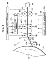
- FIG. 2 is an explanatory view illustrating a transition unit in the polymer film producing system
- FIG. 3 is an explanatory view illustrating another preferred transition unit capable of film decurling
- FIG. 4 is an explanatory view in elevation, illustrating another preferred arrangement of rotatable rollers arranged in a zigzag;
- FIG. 5 is a cross section, partially broken, illustrating a multi-manifold solution casting die
- FIG. 6 is a side elevation, partially broken, illustrating a solution casting die with plural inlet conduits
- FIG. 7 is a cross section, partially broken, illustrating a set of plural solution casting dies
- FIG. 8 is a cross section illustrating multi-layer self-supporting cast film with a second film layer extending with higher strength
- FIG. 9A is a cross section illustrating self-supporting cast film with lateral edge portions having a larger thickness
- FIG. 9B is a cross section illustrating multi-layer self-supporting cast film with lateral edge portions having a larger thickness
- FIG. 10 is a side elevation illustrating a solution casting die for producing the self-supporting cast film of FIG. 9A ;
- FIG. 11 is a cross section illustrating the same as FIG. 10 ;
- FIG. 12 is an explanatory view in elevation, illustrating a set of feed rollers including two chill rolls at lateral ends.
- Solvent for preparing dope for use in the solution casting process of the invention may be any suitable known type in the field of solvent.
- solvents include halogenated hydrocarbons, such as dichloro methane (methylene chloride); esters, such as methyl acetate; ethers; alcohols, such as methanol, ethanol, and n-butanol; and ketones, such as cetone.
- halogenated hydrocarbons such as dichloro methane (methylene chloride)
- esters such as methyl acetate
- ethers such as methyl acetate
- alcohols such as methanol, ethanol, and n-butanol
- ketones such as cetone.
- Any suitable polymers may be used in the present invention.
- Particularly preferred examples are cellulose acylates.
- a desirable example of cellulose acylate is cellulose triacetate (TAC) of which a ratio of acetylation is 59.0–62.5%.
- TAC film being used, an optical film, polarizing plate and liquid crystal display panel are characteristically excellent in view of optical performance and stability in dimensions.
- Additives of any suitable known types may be mixed with the dope.
- the additives include plasticizers such as triphenyl phosphate (TPP), and biphenyl diphenyl phosphate (BDP); ultraviolet absorbers such as oxy benzophenone compounds, and benzo triazole compounds; matte materials such as silicon dioxide; thickeners; and oil gelling agents, such as cyclohexane diamine derivative. Any of those can be mixed simultaneously with the polymer at the time of preparing the dope. Otherwise, additives can be mixed after the preparation of the dope in a manner of the in-line mixture by use of a static type of mixer during the transfer of the dope. Note that a term of the solid content is used herein to refer to a combination of the polymer and the additives.
- the above-described solid content inclusive of the polymer and additives is added to the solvent, and dissolved by any of known dissolving methods, to prepare dope.
- the dope is filtrated to eliminate foreign material.
- filter paper filter cloth, non-woven fabric, metallic mesh, sintered metal, porous plate, and other known filter mediums.
- the filtration can eliminate undissolved material in the dope as well as foreign material. Failure or occurrence of defects can be avoided when polymer film as product is completed.
- the dissolution it is possible after the dissolution to heat the dope for the purpose of raising solubility.
- methods of heating include heating in stirring the dope in a stationarily disposed tank, and heating in transferring the dope by use of a multi-pipe heat exchanger, a heat exchanger of a jacket pipe with a stationary mixer, or other heat exchangers.
- a cooling step for cooling the dope may be added after the heating step.
- the inside of the device may be pressurized to heat the dope to a temperature higher than its boiling point. According to those steps, undissolved material of fine particles can be dissolved completely. It is possible to reduce an amount of foreign material of film, and reduce load of the filtration.
- the solid content can be included in the dope in a range of 20–25 wt. % because the gel film can be provided with sufficient strength, or modulus of longitudinal elasticity, at the time of stripping the gel film from the supporting surface.
- the solid content may be included at a ratio of any suitable value.
- FIG. 1 a polymer film producing line or producing system 10 for a solution casting process is illustrated.
- FIG. 2 a transition unit 30 included in the polymer film producing system 10 as an important component is illustrated in enlargement.
- Dope 12 prepared in the above-described manner is contained in a mixing tank 11 .
- Stirring wings 13 are rotated by a motor (not shown), and stir the dope 12 in a uniform manner.
- a pump 14 sends the dope 12 to a filtration device 15 , which eliminates foreign material from the dope 12 .
- the dope 12 is sent to a solution casting die 21 at a constant flow rate.
- There is a rotating supporting drum 22 as a support disposed under the solution casting die 21 .
- a drive mechanism (not shown) with a motor drives the supporting drum 22 for rotation in an endless manner.
- a temperature adjustor 23 can be preferably connected with the supporting drum 22 , to adjust the surface temperature of the supporting drum 22 .
- a chill casting is best preferred as a mode of the solution casting of the invention.
- the surface of the supporting drum 22 can be preferably kept cooled in a range from ⁇ 10° C. to 0° C.
- a moving speed of the supporting drum 22 can be set in any value in a range of 10–200 meters per minute. Also, production of the polymer film is possible at as high a speed as 50–150 meters per minute.
- Bead 24 of the dope 12 is cast from the solution casting die 21 to the supporting drum 22 preferably to obtain a dried polymer film as product with a thickness of 15–150 microns.
- the construction of the invention is effective in quickly producing a polymer film with a thickness of 15–60 microns, namely so-called thin film.
- Gelling of the bead 24 proceeds on the supporting drum 22 , to obtain gel film 25 .
- gel film 25 is cooled and moved in the course of rotation of the supporting drum 22 , gelling of the gel film 25 proceeds to a further extent, to impart a self-supporting characteristic to the gel film 25 .
- a stripping roller 26 strips the gel film 25 from the supporting drum 22 , to form self-supporting cast film or soft film 27 .
- the self-supporting cast film 27 obtained by stripping the gel film 25 from the supporting drum 22 , is caused to keep a modulus of longitudinal elasticity of 450,000 Pa or more. This is effective in suppressing unstable feeding of the self-supporting cast film 27 in the transition unit 30 , for example suppressing occurrence of wrinkles or curls of the self-supporting cast film 27 , or residual adhesion of the self-supporting cast film 27 to rollers. Also, the control of the modulus of longitudinal elasticity can easily eliminate wrinkles and curls even if they have occurred. The processes of keeping the film strength and elimination of wrinkles or curls will be later described. Note that a value of the modulus of the longitudinal elasticity of the self-supporting cast film 27 should be preferably a value measured in extension by use of a load cell.
- the self-supporting cast film 27 can preferably have the modulus of longitudinal elasticity of 450,000 Pa or higher so that occurrence of wrinkles or curls can be suppressed in the course of feeding the self-supporting cast film 27 .
- the modulus can be more preferably 600,000 Pa or higher, and desirably 750,000 Pa or higher. Should the modulus of longitudinal elasticity be 450,000 Pa or lower, the flexural rigidity will be too low, and occurrence of curls cannot be suppressed.
- a thickness of the self-supporting cast film 27 at the stripping time can be 30 microns or more for the purpose of preventing occurrence of wrinkles due to flexing and deformation of the self-supporting cast film 27 .
- the self-supporting cast film 27 according to the invention has the thickness of 30 microns or more, preferably 30–550 microns, and desirably 50–350 microns.
- upper feed rollers 31 , 32 and 33 , and lower feed rollers 34 , 35 and 36 disposed in the transition unit 30 . Those are caused to rotate by a drive mechanism (not shown).
- the lower feed roller 34 is opposed to the upper feed roller 31 . Note that a first one of the opposed feed rollers 31 and 34 may be directly driven, while a second one of those may be originally free and caused to rotate by movement of the self-supporting cast film 27 in the rotation of the first. This applies also to a combination of the opposed feed rollers 32 and 35 , and the opposed feed rollers 33 and 36 .
- Ra microns
- the feed rollers 31 – 36 satisfy a condition of 0.05 ⁇ Ra ⁇ 0.5, preferably 0.1 ⁇ Ra ⁇ 0.4, and desirably 0.2 ⁇ Ra ⁇ 0.3.
- the construction with this range can suppress residual adhesion between the self-supporting cast film 27 and any of the feed rollers 31 – 36 .
- the surface roughness of the feed rollers 31 – 36 be 0.05 micron or less, force of adhesion to the self-supporting cast film 27 will be higher, to obstruct smooth movement of the self-supporting cast film 27 .
- the surface roughness be 0.5 micron or more, a problem will arise in that fine streaks or lines of the feed rollers 31 – 36 due to polishing will transfer to the self-supporting cast film 27 , to degrade its surface.
- Surfaces of the feed rollers 31 – 36 can have a static friction coefficient ⁇ 0 and a dynamic friction coefficient determined appropriately in order to suppress occurrence of wrinkles on the self-supporting cast film 27 .
- the static friction coefficient ⁇ 0 and the dynamic friction coefficient ⁇ are herein defined between steel and the roller surfaces. Those can satisfy conditions of 0.036 ⁇ 0 ⁇ 0.044, and 0.018 ⁇ 0.022, preferably conditions of 0.038 ⁇ 0 ⁇ 0.042, and 0.019 ⁇ 0.021, and desirably conditions of 0.039 ⁇ 0 ⁇ 0.041, and 0.0195 ⁇ 0.0205.
- the feed rollers 31 – 36 disposed in the transition unit 30 as depicted in the drawings make it possible to subject the self-supporting cast film 27 to extension by suitably setting a difference between peripheral speeds of two adjacent pairs of rollers, to prevent occurrence of wrinkles.
- V 1 be a peripheral rotational speed of the lower feed roller 35 .
- V 2 be a peripheral rotational speed of the lower feed roller 36 that is directly downstream from the lower feed roller 35 .
- the lower feed rollers 35 and 36 operate in satisfying a condition of 1.0025 ⁇ V 2 /V 1 ⁇ 1.1500, preferably 1.005 ⁇ V 2 /V 1 ⁇ 1.10, and desirably 1.01 ⁇ V 2 /V 1 ⁇ 1.05.
- V 2 /V 1 be 1.0025 or less, force of extension applied to the self-supporting cast film 27 will be too low, and cause residual adhesion of the self-supporting cast film 27 to the rollers. Should V 2 /V 1 be 1.1500 or more, it is likely that wrinkles will occur. Furthermore, it is possible to control three (3) rollers or three (3) pairs of rollers by suitably setting the ratio between the peripheral rotational speeds, so as to suppress occurrence of wrinkles more reliably. Let a be the number of rollers or number of pairs of rollers as viewed in the feeding direction. Let V n be a peripheral rotational speed of the any first one of the a rollers.
- V n+1 be a peripheral rotational speed of a second one of the a rollers that is directly downstream from the first.
- the first and second rollers operate in satisfying a condition of 1.0025 ⁇ V n+1 /V n ⁇ 1.15, preferably 1.005 ⁇ V n+1 /V n ⁇ 1.10, and desirably 1.01 ⁇ V n+1 /V n ⁇ 1.05.
- a and n satisfy a ⁇ 2, and 1 ⁇ n ⁇ a ⁇ 1.
- the straining rate in the extension of the self-supporting cast film 27 can be set as high a value of 1.4 ⁇ 10 ⁇ 4 (l/s) or more by suitably determining a ratio between the peripheral speeds V 1 , V 2 , V n and V n+1 of adjacent rollers among the feed rollers 31 – 36 . Stress in occurrence on the self-supporting cast film 27 can be raised to suppress residual adhesion of the self-supporting cast film 27 on the feed rollers 31 – 36 . Should the straining rate in the extension of the self-supporting cast film 27 be 1.4 ⁇ 10 ⁇ 4 (1/s) or less, suppression of the residual adhesion of the self-supporting cast film 27 on the feed rollers 31 – 36 will be insufficient.
- the straining rate in the extension of the self-supporting cast film 27 according to the invention can be preferably 1.4 ⁇ 10 ⁇ 3 (1/s) or more, and desirably 1.4 ⁇ 10 ⁇ 2 (1/s) or more.
- the self-supporting cast film 27 is cooled by lowering the surface temperature of the feed rollers 31 – 36 in the transition unit 30 . This is effective in raising flexural rigidity of the self-supporting cast film 27 , to suppress curls of the self-supporting cast film 27 .
- a temperature adjustor 37 is preferably used for adjusting the surface temperature of the feed rollers 31 – 36 .
- the roller temperature is set by the temperature adjustor 37 at 0° C. or lower.
- the self-supporting cast film 27 includes a first surface 27 a and a second surface 27 b .
- the first surface 27 a is a side having contacted the supporting drum 22 at the time of the gel film 25 .
- the second surface 27 b is reverse to the first surface 27 a .
- the self-supporting cast film 27 it is further preferable to blow cold gas or air 39 to the self-supporting cast film 27 by use of cooler blower assemblies 38 a and 38 b including a blower. See FIG. 2 .
- the cold gas 39 has temperature of 0° C. or lower, so that it is possible in the self-supporting cast film 27 to keep the modulus of longitudinal elasticity at 450,000 Pa or more in the course of feeding in the transition unit 30 . This is effective in raising the flexural rigidity of the self-supporting cast film 27 and in preventing occurrence of curls.
- cooler blower assembly 38 b -for the first surface 27 a may be used as a single machine being the cooler blower assembly 38 a for the second surface 27 b .
- a cooler blower assembly can be associated with two gas conduits for blowing in two positions.
- two separate cooler blower assemblies 38 a and 38 b may be used as depicted. Only the first surface 27 a may be blown with the cold gas 39 . However, it is the most preferable to blow both of the first and second surfaces 27 a and 27 b as illustrated in FIG. 2 .
- the cold gas 39 can have temperature of preferably ⁇ 10° C. or lower, and desirably ⁇ 20° C. or lower.
- cooler blower assembly is herein used to represent a combined device, which is supplied with air or other suitable gas as cooling medium, and includes a section for adjusting temperature of the gas, a section for adjusting humidity of the gas, and a blower of which a flow rate is controllable.
- the cold gas 39 is blown to the second surface 27 b to promote drying of the second surface 27 b .
- the drying speed difference dW/dt in the drying speed between the first and second surfaces 27 a and 27 b can be reduced to suppress occurrence of curls, even though the first surface 27 a is wetter, namely includes more solvent than the second surface 27 b .
- the drying speed difference dW/dt is equal to or less than 0.05 kg solvent per kg of solid per second, and preferably equal to or less than 0.03 kg solvent per kg of solid per second, and desirably equal to or less than 0.01 kg solvent per kg of solid per second.
- the value of W herein is determined as a ratio of mass of the solvent in the self-supporting cast film 27 to mass of the solid content in the same.
- Preferred example of the cold gas 39 is dry gas of which humidity is 5% or less.
- a tenter drier machine 50 as a drier is positioned downstream from the transition unit 30 as illustrated in FIG. 1 , for the purpose of further drying the self-supporting cast film 27 .
- the occurrence of curls on the self-supporting cast film 27 has been suppressed as described heretofore. Thus, no error in the entry and squeezing of the self-supporting cast film 27 into the tenter drier machine 50 will occur at its entrance.
- the self-supporting cast film 27 is extended in the width direction in a range of 1–20% to flatten the self-supporting cast film 27 by eliminating its remaining curl.
- the flattening effect might be insufficient if the extension in the width direction is 1% or less, or if the temperature is 80° C. or lower, or if the drying continues only for 10 seconds or less.
- the values of those parameters may be determined as desired in satisfying the condition of the present invention.
- W 1 (kg solvent per kg solid) be a volatilized component of the self-supporting cast film 27 .
- the operation of the tenter drier machine 50 can preferably satisfy the condition of 0.05 ⁇ W 1 ⁇ 1 while the self-supporting cast film 27 is dried in the tenter drier machine 50 .
- the volatilized component In a region of a smaller amount of the volatilized component, interactions between molecules of the polymer are likely to occur due to the small amount of the solvent. Specifically when the polymer is cellulose triacetate (TAC), these interactions will occur with higher possibility. Accordingly, stress to the self-supporting cast film 27 is higher than a region of a greater amount of the volatilized component.
- W 1 be lower than 0.05 kg solvent per kg solid, it is likely that extension of the self-supporting cast film 27 will be extremely difficult.
- W 1 be higher than 1 kg solvent per kg solid, it is likely that removal of wrinkles or curls will be insufficient.
- Polymer film 28 is created and fed out of the tenter drier machine 50 by drying the self-supporting cast film 27 .
- the polymer film 28 is sent into the drying chamber 51 .
- the rollers 52 are engaged with the polymer film 28 , and transport the polymer film 28 while the polymer film 28 is dried.
- a preferable temperature of the drying chamber 51 is in a range of 100–150° C.
- a preferable drying period of time is in a range of 5–20 minutes.
- the cooling chamber 53 it is preferable in the cooling chamber 53 to set a cooling temperature at approximately 25° C. that is a room temperature.
- the cooling temperature associated with the cooling chamber 53 according to the invention may be higher than 25° C., for example, may be as high as approximately 60° C.
- FIG. 3 is now referred to, to describe another preferred embodiment of a solution casting process of the invention. Elements similar to those of the polymer film producing system 10 in FIGS. 1 and 2 are designated with identical reference numerals.
- FIG. 3 there is a transition unit 60 , where a decurling roller 61 and a backup roller 62 are opposed to each other for nipping the self-supporting cast film 27 .
- the decurling roller 61 is disposed to face the first surface 27 a , and eliminates curls from the self-supporting cast film 27 by nipping. Pressure of the nipping may be any suitable value.
- a preferable value of the nipping pressure is 0.1–1 kPa, which is effective in eliminating curls to impart good quality to film surfaces.
- the self-supporting cast film 27 is nipped and decurled before entry into the tenter drier machine 50 . This prevents failure in squeezing of the self-supporting cast film 27 in the entry to the tenter drier machine 50 .
- decurling roller 61 and the backup roller 62 can be rotated by use of a motor.
- the second of those can be rotated by feeding of the self-supporting cast film 27 .
- two separate mechanisms with a motor may be used to cause the decurling roller 61 and the backup roller 62 respectively to rotate.
- a temperature adjustor 63 is used to cool a surface of the decurling roller 61 down to 0° C. or lower.
- the drying speed difference dW/dt between the drying speeds is 0.05 kg solvent per kg of solid per second, preferably 0.03 kg solvent per kg of solid per second, and desirably 0.01 kg solvent per kg of solid per second.
- FIGS. 1 , 2 and 3 the feed rollers in the transition unit 30 , 60 are combined in the manner of pairs each of which is positioned perpendicular to the self-supporting cast film 27 .
- feed rollers may be disposed differently.
- FIG. 4 another preferred embodiment is illustrated. Elements similar to those in the polymer film producing system 10 of FIGS. 1 and 2 are designated with identical reference numerals.
- a transition unit 70 contains upper decurling rollers 71 and 72 for nipping, and lower rotatable rollers 73 , 74 and 75 disposed in a zigzag manner relative to the upper decurling rollers 71 and 72 on an opposite side with respect to the self-supporting cast film 27 .
- the disposition of the decurling and rotatable rollers 71 – 75 suppresses occurrence of curls because of downward force applied to the second surface 27 b . If a curl occurs, it is easily possible to decurl the self-supporting cast film 27 .
- a temperature adjustor, and a cooler blower assembly can be used.
- the rollers may be associated with a drive mechanism (not shown). Any suitable one of the rollers may be designated for direct connection with the drive mechanism.
- solution casting process of the one-layer type has been described heretofore according to the solution casting die 21 for the one-layer solution casting.
- a solution casting process of the invention is not limited to that illustrated in FIGS. 1–4 .
- a supporting belt or band can be used instead of the supporting drum 22 as a support.
- Other embodiments are hereinafter described with reference to drawings. Elements similar to those of the polymer film producing system 10 in FIG. 1 are designated with identical reference numerals.
- a multi-manifold solution casting die 83 includes plural manifolds 80 , 81 and 82 , which are supplied with respectively dope 84 , high-density dope 85 and dope 86 . There is a convergence point 87 where the flows of the dope are unified.
- a supporting belt 88 as a support is located under the multi-manifold solution casting die 83 , and receives the dope 84 , 85 and 86 cast thereon. Gel film 89 is formed, and stripped to advance a self-supporting film. The polymer film will be described later.
- FIG. 6 there is a solution casting die 100 .
- a feed block 101 is positioned upstream from the solution casting die 100 .
- Inlet conduits 101 a , 101 b and 101 c are connected with the feed block 101 .
- Dope 102 , high-density dope 103 and dope 104 is supplied by a dope supply device (not shown), and sent through the inlet conduits 101 a– 101 c to the feed block 101 .
- the feed block 101 causes convergence of the dope 102 – 104 .
- Gel film 106 is formed on the supporting belt 105 , and stripped as self-supporting cast film, which is dried to obtain polymer film.
- the polymer film produced according to the multi-layer solution casting process will be described later in detail. Note that a rotating supporting drum may be used instead of the supporting belt 105 of FIGS. 5 and 6 .
- FIG. 7 another preferred solution casting process of a successive type according to the invention is illustrated.
- Three solution casting dies 110 , 111 and 112 are arranged on one line over a supporting belt 113 as a support.
- the solution casting dies 110 , 111 and 112 are supplied with respectively dope 114 , high-density dope 115 and dope 116 by a dope supply device (not shown).
- the dope 114 – 116 is successively cast on to the supporting belt 113 in three serially arranged portions.
- Gel film 117 is formed, and stripped to advance a self-supporting cast film, which is dried to constitute polymer film. The polymer film will be described later.
- self-supporting cast film or soft film 120 of a triple-layer structure is illustrated as cast film obtained by any of the multi-layer solution casting processes of FIGS. 5–7 which include multi-manifold solution casting and successive solution casting.
- the self-supporting cast film 120 includes a first film layer 123 , a second film layer 122 overlaid on the first film layer 123 , and a third film layer 121 overlaid on the second film layer 122 .
- the high-density dope 85 ( FIG. 5 ), the high-density dope 103 ( FIG. 6 ) and the high-density dope 115 ( FIG. 7 ) for forming the second film layer 122 has higher density than the dope 84 and 86 ( FIG. 5 ), the dope 102 and 104 ( FIG. 6 ), and the dope 114 and 116 ( FIG. 7 ) for forming the third film layer 121 and the first film layer 123 .
- the second film layer 122 has a higher strength.
- the second film layer 122 is cast by use of the high-density dope.
- Each of the first and third film layers 121 and 123 is cast by use of the dope with lower density than the high-density dope. Consequently, layers with higher film strength are formed particularly in lateral edge portions 120 a and 120 b , which should be specially protected from curls.
- the dope for the first and third film layers 121 and 123 has the normal density which is effective in obtaining high quality of the outer surfaces of the polymer film.
- L 1 (mm) be a size or width of the lateral edge portions 120 a and 120 b as measured from lateral edges 120 c and 120 d of the self-supporting cast film 120 .
- the most preferable value of L 1 is 10 mm.
- a preferred example of the high-density dope may include 20–25 wt. % of the solid content, so that the lateral edge portions 120 a and 120 b of the self-supporting cast film 120 can have the modulus of the longitudinal elasticity of 450,000 Pa or more.
- a preferred example of the dope with the lower density may include 15–20 wt. % of the solid content for obtaining high quality in the surfaces.
- the dope used herein may have any suitable density.
- the number of the layers formed according to the multi-layer solution casting may be two, or four or more instead of the three.
- Self-supporting cast film or soft film 130 in FIG. 9A includes a middle portion 130 c and lateral edge portions 130 a and 130 b having a greater thickness than the middle portion 130 c .
- a solution casting die 140 in FIGS. 10 and 11 is used.
- a dope supply conduit 141 is connected with the solution casting die 140 .
- Dope 143 is caused to flow through the dope supply conduit 141 in a path 142 to the solution casting die 140 .
- a manifold 144 in the solution casting die 140 spreads the flow of the dope 143 to a width of the casting.
- a die channel 146 in the solution casting die 140 causes a die lip 147 to cast the dope 143 on to a supporting surface (not shown).
- Deckle panels 148 for spreading define inner surfaces of the die channel 146 .
- the surfaces of the deckle panels 148 are inclined at an angle D of the inclination relative to the die lip 147 .
- a sign W 2 is used to denote a width of the die channel 146 at the die lip 147 in a direction of the thickness of the bead. See FIG. 10 .
- A (microns) be a thickness of the lateral edge portions 130 a and 130 b of the self-supporting cast film 130 .
- B (microns) be a thickness of the middle portion 130 c which is other than the lateral edge portions 130 a and 130 b in the self-supporting cast film 130 .
- the solution casting die 140 is constructed by optimizing the inclination angle D and the die channel width W 2 of the die channel 146 . This enables casting in the condition of A>B.
- the flexural rigidity of a thin object is directly proportional to the cube of the thickness of the object.
- the control of the thickness A of the lateral edge portions 130 a and 130 b is effective for controlling the curls.
- the most preferable value of the width L 1 of the lateral edge portions 130 a and 130 b is 10 mm.
- the thickness A (microns) of the lateral edge portions 130 a and 130 b satisfies a condition 30 ⁇ A ⁇ 560, preferably 100 ⁇ A ⁇ 400, and desirably 150 ⁇ A ⁇ 350. Should the thickness A be 30 microns or less, it is likely that a small curl will remain without being suppressed. Should the thickness A be 560 microns or more, residual deposit of the polymer will remain on the supporting surface particularly in the case of the high amount of the volatilized component in the self-supporting cast film 130 .
- a ratio between the thicknesses A and B can preferably satisfy a condition of 1 ⁇ A/B ⁇ 5.
- ratio A/B be smaller than 1, no effect of suppressing curls will be obtained because of too small a difference in the flexural rigidity. Should the ratio A/B be greater than 5, feeding of the self-supporting cast film 27 will be influenced, for example because a partially remaining portion of the self-supporting cast film 130 will be stuck on the supporting surface.
- the width W 2 (microns) of the die lip 147 satisfies a condition 500 ⁇ W 2 ⁇ 2,000, preferably 700 ⁇ W 2 ⁇ 1,500, and desirably 800 ⁇ W 2 ⁇ 1,000.
- the inclination angle D (degrees) of the deckle panels 148 satisfies a condition 30 ⁇ D ⁇ 90, preferably 40 ⁇ D ⁇ 70, and desirably 50 ⁇ D ⁇ 60.
- the self-supporting cast film according to the invention may have a multi-layer form unlike that of FIG. 159A .
- FIG. 9B a triple-layer structure of self-supporting cast film or soft film 131 is obtained by multi-layer solution casting, or either one of the multi-manifold solution casting and successive solution casting.
- Lateral edge portions 131 a and 131 b can preferably satisfy the above-described condition related to the self-supporting cast film 130 .
- a middle portion 131 c is included in the self-supporting cast film 131 , and has the thickness B.
- the ratio between A and B can preferably satisfy the above-described condition related to the self-supporting cast film 130 .
- the symbol of the thickness A is used to denote the smaller thickness of those of the lateral edge portions 131 a and 131 b .
- the term of the middle portion 131 c is used to mean a portion to become a product of polymer film obtained after slitting.
- the number of the layers formed by the multi-layer solution casting may be two, or four or more in place of the three.
- a feed roller set 150 is constituted by an upper feed roller 151 and a lower feed roller 152 .
- the upper feed roller 151 is disposed to contact the first surface 27 a of the self-supporting cast film 27 .
- the lower feed roller 152 is disposed to contact the second surface 27 b of the self-supporting cast film 27 .
- a drive mechanism (not shown) causes the upper and lower feed rollers 151 and 152 to rotate, to feed the self-supporting cast film 27 in the transition unit 30 .
- the lower feed roller 152 is constituted by a middle roll 152 b , and first and second chill rolls 152 a and 152 c disposed at ends of the middle roll 152 b .
- Coolant supply conduits 153 and 154 are associated with the first and second chill rolls 152 a and 152 c , and cause coolant to flow for the cooling operation of the first and second chill rolls 152 a and 152 c .
- Paths 155 and 156 connect the coolant supply conduit 153 to the temperature adjustor 37 .
- paths 157 and 158 connect the coolant supply conduit 154 to the temperature adjustor 37 .
- a temperature sensor (not shown), which measures the temperature of the first and second chill rolls 152 a and 152 c . According to the measured temperature, coolant is caused to flow through the path 155 , the coolant supply conduit 153 , the first chill roll 152 a and the path 156 . A lateral edge portion 27 c is cooled by the first chill roll 152 a . Also, coolant is caused to flow through the path 157 , the coolant supply conduit 154 , the second chill roll 152 c and the path 158 . A lateral edge portion 27 d is cooled by the second chill roll 152 c . This encourages condensation of the gaseous solvent in the lateral edge portions 27 c and 27 d on the second surface 27 b .
- the drying speed difference between the second surface 27 b and the first surface 27 a can be reduced, to minimize the curled degree.
- L 2 be a size of the first and second chill rolls 152 a and 152 c as measured from lateral edges 27 e and 27 f in the width direction of the self-supporting cast film 27 . It is preferable that L 2 is 10 mm.
- the coolant may include glycol types, fluorine types, alcohol types and the like, and may be a mixture of at least two of those.
- rollers for cooling the second surface 27 b may not be combined in plural pairs in each of which two rollers are opposed directly to each other as illustrated in FIG. 12 .
- the decurling and rotatable rollers 71 – 75 in FIG. 4 are disposed in the zigzag form in the transition unit 70 .
- At least one of the lower rotatable rollers 73 – 75 can be constructed for cooling for the purpose of suppressing occurrence of curls.
- the polymer film According to the solution casting of the invention, it is easily possible to produce the polymer film with a small thickness of 15–150 microns.
- the thickness of the polymer film is preferably 35–65 microns, and desirably 35–60 microns.
- the polymer film 28 obtained by the solution casting of the present invention can be used as an optical film or protective film on a polarizing plate.
- a polarizing plate protective film can be attached to each of two surfaces of a polarizing film formed from polyvinyl alcohol or other polymers, so as to construct a polarizing plate.
- Further examples of uses of the polymer film 28 include an optical compensation film, anti-reflection film, and the like.
- the optical compensation film includes the polymer film 28 and an optical compensation sheet attached to the polymer film 28 .
- the anti-reflection film includes the polymer film 28 and an anti-glare layer overlaid thereon.
- a liquid crystal display panel or display device can be constructed by use of such film with high quality, because high quality of the surfaces of the polymer film 28 can be obtained.
- Experiment 1 was conducted for observing wrinkles of the self-supporting film and residual adhesion to the self-supporting rollers.
- Experiment 2 was conducted for observing occurrence of curls. Specifically, portions of the condition in Experiment 2 the same as those of Experiment 1 are not further described.
- Experiment 2 details of the condition are described with Examples 2–4 and Comparable examples 7 and 8. Portions of the condition in Examples 3 and 4 and Comparable examples 7 and 8 the same as those of Example 2 are not further described. Results in relation to the condition are indicated in Table 2.
- the solvent was constituted by mixture of 85 wt. % of dichloro methane, 12 wt. % of methanol, and 3 wt. % of n-butanol. A ratio of the mixed solvent was 100 parts by weight.
- the solid content or solute polymer had 26.8 parts by weight of cellulose triacetate (TAC) with a ratio of acetylation of 60.9%.
- Plasticizers as additives were added to the solvent, and included 2.1 parts by weight of triphenyl phosphate (TPP), and 1.1 parts by weight of biphenyl diphenyl phosphate (BDP). Thus, the dope A was obtained.
- the dope A had viscosity of 100 Pa ⁇ s at the temperature of 30° C., storage modulus of elasticity of 100,000 Pa at the temperature of ⁇ 5° C. Then the dope A was contained in the mixing tank 11 . It is to be noted that the value of parts by weight of the solute is used to mean a proportion relative to the amount of the mixed solvent.
- the solvent was constituted by mixture of 85 wt. % of methyl acetate, 5 wt. % of acetone, 5 wt. % of ethanol, and 5 wt. % of n-butanol.
- a ratio of the mixed solvent was 100 parts by weight.
- the solid content or solute polymer had 26.8 parts by weight of cellulose triacetate (TAC) with a ratio of acetylation of 59.6%.
- Plasticizers as additives were added to the solvent, and included 2.1 parts by weight of triphenyl phosphate (TPP), and 1.1 parts by weight of biphenyl diphenyl phosphate (BDP).
- TPP triphenyl phosphate
- BDP biphenyl diphenyl phosphate
- the polymer film producing system 10 in FIG. 1 was used for the polymer film production.
- the solution casting die 21 was a coat hanger type of die.
- a surface of the supporting drum 22 was subjected to plating of hard chromium, and finished according to the mirror surface finish in order to impart a surface roughness of 0.04 S to the supporting drum 22 .
- the feed rollers 31 – 36 in the transition unit 30 had surface roughness Ra of 0.2 micron, static friction coefficient ⁇ 0 of 0.04, and dynamic friction coefficient ⁇ of 0.02.
- the ratio V 2 /V 1 of the peripheral speed V 2 of the lower feed roller 36 to the peripheral speed V 1 of the lower feed roller 35 was determined 1.05.
- the ratio V 1 /V 0 of the peripheral speed V 1 of the lower feed roller 35 to the peripheral speed V 0 of the lower feed roller 34 was also determined 1.05.
- the dope A at 30° C. was cast on to the supporting drum 22 at the casting speed of 50 meters per minute in a manner of targeting a thickness of 40 microns for the polymer film 28 after being dried.
- the gel film 25 is stripped by the stripping roller 26 to obtain the self-supporting cast film 27 .
- the modulus of longitudinal elasticity of the self-supporting cast film 27 was measured by use of a load cell, and was found 500,000 Pa.
- the self-supporting cast film 27 was 60 microns thick.
- the cooler blower assembly 38 b beside the first surface 27 a blew the cold gas 39 at ⁇ 5° C.
- the self-supporting cast film 27 was dried in the tenter drier machine 50 at 135° C. for three (3) minutes, and then dried in the drying chamber 51 at 145° C. for 15 minutes, and cooled in the cooling chamber 53 at 60° C. for two (2) minutes.
- the polymer film 28 was obtained, and wound by the winder 54 .
- the polymer film 28 was observed by human eyes. As a result, a good product was obtained because of no occurrence of wrinkles (A), no occurrence of residual adhesion to the feed rollers 31 – 36 (A). Also, retardation of surfaces of the polymer film 28 was measured, and was found 2 nm.
- the polymer film 28 being obtained had good optical quality because of no optical anisotropy.
- Example 1 The solution casting of the condition was the same as Example 1 but with differences specifically indicated in Table 1.
- Comparable example 2 the self-supporting film was cast with a thickness of 25 microns for the purpose of finely forming the polymer film with a thickness of 17 microns.
- the condition and results of the experiment are indicated in Table 1.
- Example 1 Example 2
- Example 3 Modulus (Pa) 500,000 400,000 500,000 500,000 of longitudinal elasticity Thickness 60 25 25 60 (microns) of the cast film 27 upon being stripped Temperature ⁇ 5 3 ⁇ 5 ⁇ 5 (° C.) of the cast film 27 Surface rough- 0.2 0.04 0.2 0.04 ness Ra (microns) of the feed rollers Static friction 0.04 0.034 0.04 0.04 coefficient ⁇ 0 Dynamic 0.02 0.017 0.02 0.02 friction coefficient ⁇ Ratio V2/V1 1.05 1.002 1.05 1.05 between the peripheral speeds Straining rate 1.4 ⁇ 10 ⁇ 3 1.3 ⁇ 10 ⁇ 3 1.4 ⁇ 10 ⁇ 3 1.4 ⁇ 10 ⁇ 3 (1/s) in the extension of the cast film 27 Occurrence of A C B A wrinkles Occurrence of A C A B residual adhesion Comp.
- Example 1 resulted in high quality because of successful suppression of wrinkles and residual adhesion.
- Comparable examples 2–6 had lower quality than Example 1 because of wrinkles and/or residual adhesion, but usable in a limited manner according to a product for use with the polymer film.
- the construction of Comparable examples 2–6 can be included in the scope of the present invention.
- Polymer film was produced by the polymer film producing system 10 of FIG. 1 the same as that of Example 1.
- the temperature adjustor 23 was operated to keep the surface of the supporting drum 22 at the temperature of ⁇ 5° C.
- the feed rollers 31 – 36 had the surface roughness Ra of 0.2 micron, the static friction coefficient ⁇ 0 of 0.04, and the dynamic friction coefficient ⁇ of 0.02.
- the ratio V 2 /V 1 of the peripheral speed V 2 of the lower feed roller 36 to the peripheral speed V 1 of the lower feed roller 35 was 1.05.
- the ratio V 1 /V 0 of the peripheral speed V 1 of the lower feed roller to the peripheral speed V 0 of the lower feed roller 34 was also 1.05.
- the dope A at 30° C. was cast on to the supporting drum 22 at the casting speed of 80 meters per minute with a purpose of obtaining a thickness of 40 microns for the polymer film 28 after being dried.
- the gel film 25 was stripped by the stripping roller 26 to obtain the self-supporting cast film 27 .
- the modulus of longitudinal elasticity of the self-supporting cast film 27 was measured by a load cell, and found 500,000 Pa.
- the self-supporting cast film 27 was 60 microns thick.
- the temperature adjustor 37 was operated to keep the surface of the feed rollers 31 – 36 at the temperature of ⁇ 5° C.
- the drying speed difference dW/dt between the first and second surfaces 27 a and 27 b in the transition unit 30 was 0.04 kg solvent per kg of solid per second.
- the thickness A of the lateral edge portions 130 a and 130 b of the self-supporting cast film 27 was 25 microns.
- the ratio A/B of A to the thickness B of the middle portion 130 c was 0.42. See FIG. 9A .
- the self-supporting cast film 27 was extended and dried by the tenter drier machine 50 at 120° C. and at an extension ratio of 4% in the width direction for 10 seconds.
- the amount W 1 of the volatilized component of the solvent was 15 wt. %. Then the self-supporting cast film 27 was dried in the drying chamber 51 at 145° C.
- the whole surface of the polymer film after being dried was evaluated for curls according to the following process.
- Samples were cut and obtained from the polymer film at a size being 3 ⁇ 35 mm in a long shape as viewed in the width direction of the polymer film.
- the samples were kept dipped in water of 20–25° C. for three (3) minutes. After this, the curled amount was observed by human eyes viewing vertically downwards. The smallest unit of the measurement was 0.1 mm.
- Five (5) points arranged in the width direction were taken out from each of the samples, to determine an average curled amount Cav (cm ⁇ 1 ). The following is grades of the evaluation.
- Cav was 1 cm ⁇ 1 , and found excellent as a product of grade A.
- the lateral edge portions of the polymer film in the dried state were sampled in the same process as that for the whole surface curls in the Item 1 , and subjected to the processing, measurement and evaluation.
- the average curled amount of the lateral edge portions was 1.5 cm ⁇ 1 , and found excellent as a product of grade A.
- the producing system the same as Example 2 was used but with a difference of a change in the polymer film producing system 10 to that illustrated in FIG. 3 .
- the decurling roller 61 had the surfaces kept at the temperature of ⁇ 5° C. by the temperature adjustor 63 .
- the dope B at 30° C. was cast on to the supporting drum 22 at the casting speed of 80 meters per minute with a purpose of providing the polymer film 28 with a thickness of 40 microns after being dried.
- the gel film 25 was stripped by the stripping roller 26 to obtain the self-supporting cast film 27 .
- the modulus of longitudinal elasticity of the self-supporting cast film 27 was measured by use of a load cell, and was found 450,000 Pa.
- the self-supporting cast film 27 was 60 microns thick.
- the feed rollers 31 – 36 had the surface kept at 2° C. by the temperature adjustor 63 .
- the decurling roller 61 was used to nip the self-supporting cast film 27 at the pressure of 0.2 kPa.
- the drying speed difference dW/dt between the first and second surfaces 27 a and 27 b inside the transition unit 30 was 0.02 kg solvent per kg of solid per second. After this, the condition was set without differences from that of Example 2.
- Retardation of surfaces of the polymer film 28 was measured, and was found 1.8 nm.
- the basic construction of the polymer film producing system 10 was the same as Example 2 but with a difference in that the surface of the supporting drum 22 was kept at 20° C.
- the dope B at 30° C. was cast on to the supporting drum 22 so as to provide the polymer film 28 with a thickness of 40 microns after being dried.
- the gel film 25 was stripped by the stripping roller 26 to obtain the self-supporting cast film 27 .
- the modulus of longitudinal elasticity of the self-supporting cast film 27 was measured by use of a load cell, and was found 450,000 Pa.
- the self-supporting cast film 27 was 60 microns thick.
- the upper feed rollers 31 and 32 and the lower feed rollers 34 and 35 had the surface kept at 2° C. by the temperature adjustor 63 .
- the drying speed difference dW/dt between the first and second surfaces 27 a and 27 b inside the transition unit 30 was 0.06 kg solvent per kg of solid per second. After this, the condition was set without differences from that of Example 2. Retardation of surfaces of the polymer film 28 was measured, and was found 1.5 nm. The polymer film 28 being obtained had good optical quality because of no optical anisotropy. According to the measuring process the same as Example 2, curls of the whole surfaces and the lateral edge portions were measured. As a result of Example 4, the curled amount was excellent for a product because of the small curled amount.
- Comparable example 7 had clearly remaining curls of the whole surfaces with the grade C, and clearly remaining curls of the lateral edge portions with the grade C.
- Comparable example 8 had occasionally limited remaining curls of the whole surfaces with the grade B, but had no remaining curls of the lateral edge portions with the grade A.
- the polymer film of Comparable example 8 had a small difficulty in relation to curls of the whole surfaces, but usable in a limited manner according to a product for use with the polymer film.
- the construction of Comparable example 8 can be included in the scope of the present invention.
Abstract
Description
1≦A/B≦5.
| TABLE 1 | ||||
| Comp. | Comp. | Comp. | ||
| Example 1 | Example 1 | Example 2 | Example 3 | |
| Modulus (Pa) | 500,000 | 400,000 | 500,000 | 500,000 |
| of | ||||
| elasticity | ||||
| Thickness | ||||
| 60 | 25 | 25 | 60 | |
| (microns) of | ||||
| the |
||||
| upon being | ||||
| stripped | ||||
| Temperature | −5 | 3 | −5 | −5 |
| (° C.) of the | ||||
| |
||||
| Surface rough- | 0.2 | 0.04 | 0.2 | 0.04 |
| ness Ra | ||||
| (microns) of | ||||
| the feed rollers | ||||
| Static friction | 0.04 | 0.034 | 0.04 | 0.04 |
| coefficient μ0 | ||||
| Dynamic | 0.02 | 0.017 | 0.02 | 0.02 |
| friction | ||||
| coefficient μ | ||||
| Ratio V2/V1 | 1.05 | 1.002 | 1.05 | 1.05 |
| between the | ||||
| peripheral | ||||
| speeds | ||||
| Straining rate | 1.4 × 10⁻³ | 1.3 × 10⁻³ | 1.4 × 10⁻³ | 1.4 × 10⁻³ |
| (1/s) in the | ||||
| extension of | ||||
| the |
||||
| Occurrence of | A | C | B | A |
| wrinkles | ||||
| Occurrence of | A | C | A | B |
| residual | ||||
| adhesion | ||||
| Comp. | Comp. | Comp. | |
| Example 4 | Example 5 | Example 6 | |
| Modulus (Pa) of | 500,000 | 500,000 | 500,000 |
| longitudinal elasticity | |||
| Thickness (microns) of | 60 | 60 | 60 |
| the |
|||
| being stripped | |||
| Temperature (° C.) of | −5 | −5 | −5 |
| the |
|||
| Surface roughness Ra | 0.2 | 0.2 | 0.2 |
| (microns) of the feed | |||
| rollers | |||
| Static friction | 0.04 | 0.04 | 0.034 |
| coefficient μ0 | |||
| Dynamic friction | 0.02 | 0.02 | 0.017 |
| coefficient μ | |||
| Ratio V2/V1 between | 1.2 | 1.05 | 1.05 |
| the peripheral speeds | |||
| Straining rate (1/s) | 1.4 × 10⁻³ | 1.3 × 10⁻⁴ | 1.4 × 10⁻³ |
| in the extension of | |||
| the |
|||
| Occurrence of wrinkles | B | A | B |
| Occurrence of residual | A | B | A |
| adhesion | |||
| In Table 1, the signs A–C mean the following. | |||
| A: No occurrence of wrinkles or residual adhesion, | |||
| B: Occasionally limited occurrence of wrinkles or residual adhesion. | |||
| C: Clearly considerable occurrence of wrinkles or residual adhesion. | |||
| TABLE 2 | ||||||
| Comp. | Comp. | |||||
| Ex. 2 | Ex. 3 | Ex. 4 | Ex. 7 | Ex. 8 | ||
| Dope type | A | B | B | A | A |
| Roller | −5 | 2 | 2 | 15 | −5 |
| temperature | |||||
| (° C.) | |||||
| Modulus | 500 | 450 | 450 | 300 | 500 |
| (× 103 Pa) of | |||||
| longitudinal | |||||
| elasticity | |||||
| Drying speed | 0.04 | 0.02 | 0.06 | 0.06 | 0.04 |
| difference | |||||
| Use of the | — | o | — | — | — |
| decurling | |||||
| |
|||||
| Temperature | — | −5 | — | — | — |
| (° C.) of the | |||||
| | |||||
| roller | |||||
| 61 | |||||
| |
25 | 25 | 66 | 25 | 66 |
| (microns) of | |||||
| the lateral | |||||
| edge portions | |||||
| Ratio A/B of | 0.42 | 0.42 | 1.1 | 0.42 | 1.1 |
| the thicknesses | |||||
| Factor (%) of | 4 | 4 | 4 | 4 | 0.5 |
| extension in | |||||
| the |
|||||
| |
120 | 120 | 120 | 120 | 70 |
| temperature | |||||
| (° C.) | |||||
| Amount (wt. %) | 15 | 15 | 15 | 15 | 4 |
| of volatilized | |||||
| solvent | |||||
| Curls of the | A | A | A | C | B |
| whole surface | |||||
| Curls of the | A | A | A | C | A |
| lateral edge | |||||
| portions | |||||
| In Table 2, the unit of the drying speed difference is kg solvent per kg of solid per second. | |||||
| A: No occurrence of curls, | |||||
| B: Occasionally limited occurrence of curls, | |||||
| C: Clearly considerable occurrence of curls. | |||||
Claims (15)
Applications Claiming Priority (2)
| Application Number | Priority Date | Filing Date | Title |
|---|---|---|---|
| JP2002-340808 | 2002-11-25 | ||
| JP2002340808A JP4280486B2 (en) | 2002-11-25 | 2002-11-25 | Solution casting method |
Publications (2)
| Publication Number | Publication Date |
|---|---|
| US20040104496A1 US20040104496A1 (en) | 2004-06-03 |
| US7172713B2 true US7172713B2 (en) | 2007-02-06 |
Family
ID=32375829
Family Applications (1)
| Application Number | Title | Priority Date | Filing Date |
|---|---|---|---|
| US10/720,537 Expired - Fee Related US7172713B2 (en) | 2002-11-25 | 2003-11-25 | Solution casting process for producing polymer film |
Country Status (2)
| Country | Link |
|---|---|
| US (1) | US7172713B2 (en) |
| JP (1) | JP4280486B2 (en) |
Cited By (21)
| Publication number | Priority date | Publication date | Assignee | Title |
|---|---|---|---|---|
| US20090085244A1 (en) * | 2007-09-28 | 2009-04-02 | Yukihiro Katai | Method for removing solvent from polymer solution |
| US20090203900A1 (en) * | 2008-02-13 | 2009-08-13 | Eastman Chemical Comapany | Production of cellulose esters in the presence of a cosolvent |
| US20100267942A1 (en) * | 2009-04-15 | 2010-10-21 | Eastman Chemical Company | Regioselectively substituted cellulose esters produced in a tetraalkylammonium alkylphosphate ionic liquid process and products produced therefrom |
| US20110213138A1 (en) * | 2008-02-13 | 2011-09-01 | Eastman Chemical Company | Regioselectively substituted cellulose esters produced in a halogenated ionic liquid process and products produced therefrom |
| WO2012003118A1 (en) | 2010-07-02 | 2012-01-05 | Eastman Chemical Company | Multilayer cellulose ester film having reversed optical dispersion |
| US8273872B2 (en) | 2008-02-13 | 2012-09-25 | Eastman Chemical Company | Cellulose esters and their production in halogenated ionic liquids |
| WO2012141901A1 (en) | 2011-04-13 | 2012-10-18 | Eastman Chemical Company | Cellulose ester optical films |
| US9156918B2 (en) | 2008-02-13 | 2015-10-13 | Eastman Chemical Company | Treatment of cellulose esters |
| US9309360B2 (en) | 2013-12-17 | 2016-04-12 | Eastman Chemical Company | Cellulose ester based quarter wave plates having normal wavelength dispersion |
| US9309362B2 (en) | 2013-12-17 | 2016-04-12 | Eastman Chemical Company | Optical films containing optical retardation-enhancing additive |
| US9777074B2 (en) | 2008-02-13 | 2017-10-03 | Eastman Chemical Company | Regioselectively substituted cellulose esters produced in a halogenated ionic liquid process and products produced therefrom |
| WO2017184394A1 (en) | 2016-04-22 | 2017-10-26 | Eastman Chemical Company | Regioselectively substituted cellulose esters and films made therefrom |
| US9834516B2 (en) | 2007-02-14 | 2017-12-05 | Eastman Chemical Company | Regioselectively substituted cellulose esters produced in a carboxylated ionic liquid process and products produced therefrom |
| WO2018183467A1 (en) | 2017-03-29 | 2018-10-04 | Eastman Chemical Company | Regioselectively substituted cellulose esters |
| US10174129B2 (en) | 2007-02-14 | 2019-01-08 | Eastman Chemical Company | Regioselectively substituted cellulose esters produced in a carboxylated ionic liquid process and products produced therefrom |
| WO2019190756A1 (en) | 2018-03-28 | 2019-10-03 | Eastman Chemical Company | Regioselectively substituted cellulose esters |
| CN111236669A (en) * | 2020-01-16 | 2020-06-05 | 中铁二局集团有限公司 | Super high-rise concrete and maintenance layer spraying system thereof |
| WO2021041018A1 (en) | 2019-08-26 | 2021-03-04 | Eastman Chemical Company | 2-ethylhexanoyl substituted cellulose esters |
| WO2023086532A1 (en) | 2021-11-12 | 2023-05-19 | Eastman Chemical Company | Freshwater biodegradable mixed ester cellulose esters |
| US11890801B2 (en) | 2019-08-09 | 2024-02-06 | Processing Technologies International, LLC | Method and system for processing an extruded sheet |
| US11926736B1 (en) | 2023-02-17 | 2024-03-12 | Thintronics, Inc. | Curable film composition, curable film, and cured product thereof |
Families Citing this family (23)
| Publication number | Priority date | Publication date | Assignee | Title |
|---|---|---|---|---|
| JP4390264B2 (en) * | 2004-03-29 | 2009-12-24 | 富士フイルム株式会社 | Multilayer film manufacturing apparatus and manufacturing method thereof |
| DE202005006412U1 (en) * | 2004-05-27 | 2005-06-30 | Battenfeld Extrusionstechnik Gmbh | cooler |
| JP4749741B2 (en) * | 2005-03-04 | 2011-08-17 | 富士フイルム株式会社 | Tenta dryer and solution casting method |
| DE102005011040A1 (en) * | 2005-03-08 | 2006-09-14 | Nordson Corp., Westlake | Method and device for producing and applying an elastic strand material |
| JP2006297920A (en) * | 2005-03-25 | 2006-11-02 | Fuji Photo Film Co Ltd | Polymer film and method for manufacturing it |
| US7611760B2 (en) * | 2005-04-22 | 2009-11-03 | Fujifilm Corporation | Cellulose acylate film, optical compensation film, polarizing plate and liquid crystal display |
| JP4774901B2 (en) * | 2005-10-07 | 2011-09-21 | 東洋紡績株式会社 | Method for producing polyimide film |
| WO2007074588A1 (en) * | 2005-12-26 | 2007-07-05 | Konica Minolta Opto, Inc. | Process for producing cellulose film, apparatus for producing cellulose film, optical film produced by said production apparatus, polarizing plate using said optical film, and liquid crystal display device |
| JP4807073B2 (en) * | 2005-12-28 | 2011-11-02 | 東洋紡績株式会社 | Method for producing polyimide film |
| JP4901249B2 (en) * | 2006-03-17 | 2012-03-21 | 富士フイルム株式会社 | Method for producing polymer film |
| JP4823783B2 (en) * | 2006-06-26 | 2011-11-24 | 富士フイルム株式会社 | Method for producing polymer film |
| TWI399276B (en) * | 2006-08-16 | 2013-06-21 | Fujifilm Corp | Casting device, solution casting apparatus, and solution casting method |
| JP4989529B2 (en) * | 2007-03-20 | 2012-08-01 | 富士フイルム株式会社 | Method for producing cellulose acylate film |
| US20080268244A1 (en) * | 2007-04-30 | 2008-10-30 | Doufas Antonios K | Impact copolymers having improved properties |
| WO2009079206A1 (en) * | 2007-12-17 | 2009-06-25 | Dow Global Technologies Inc. | Shaping die and its use in a solid state drawing process |
| JP5592670B2 (en) * | 2010-03-02 | 2014-09-17 | 富士フイルム株式会社 | Solution casting equipment and method |
| DE102011003604A1 (en) | 2011-02-03 | 2012-08-09 | Battenfeld-Cincinnati Germany Gmbh | Cooling device and cooling method |
| CN103934938B (en) * | 2014-04-17 | 2016-03-23 | 常州纺织服装职业技术学院 | The dryness finalization technique of poly-1,3, the 4-oxadiazole cast film of aromatic series |
| JP6558092B2 (en) * | 2015-06-16 | 2019-08-14 | コニカミノルタ株式会社 | Manufacturing method of resin film |
| JP6665512B2 (en) * | 2015-12-14 | 2020-03-13 | コニカミノルタ株式会社 | Optical film manufacturing method |
| CA3018516A1 (en) | 2017-09-26 | 2019-03-26 | Davis-Standard, Llc | Casting apparatus for manufacturing polymer film |
| CN109968574B (en) * | 2019-05-16 | 2024-02-06 | 江苏科润膜材料有限公司 | Steel belt casting device for producing enhanced perfluorinated ion exchange membrane and membrane manufacturing method thereof |
| CN116872418B (en) * | 2023-09-08 | 2023-12-05 | 山东圣和薄膜新材料有限公司 | Sheet casting machine capable of preventing two sides of film from shrinking |
Citations (3)
| Publication number | Priority date | Publication date | Assignee | Title |
|---|---|---|---|---|
| GB2114050A (en) | 1982-01-20 | 1983-08-17 | Tetra Pak Int | Thermoplastic film extruding t-die |
| JP2001315147A (en) | 2000-05-10 | 2001-11-13 | Konica Corp | Producing method for cellulose ester film |
| US6660211B2 (en) * | 2001-04-23 | 2003-12-09 | Kimberly-Clark Worldwide, Inc. | Methods of making biodegradable films having enhanced ductility and breathability |
-
2002
- 2002-11-25 JP JP2002340808A patent/JP4280486B2/en not_active Expired - Fee Related
-
2003
- 2003-11-25 US US10/720,537 patent/US7172713B2/en not_active Expired - Fee Related
Patent Citations (3)
| Publication number | Priority date | Publication date | Assignee | Title |
|---|---|---|---|---|
| GB2114050A (en) | 1982-01-20 | 1983-08-17 | Tetra Pak Int | Thermoplastic film extruding t-die |
| JP2001315147A (en) | 2000-05-10 | 2001-11-13 | Konica Corp | Producing method for cellulose ester film |
| US6660211B2 (en) * | 2001-04-23 | 2003-12-09 | Kimberly-Clark Worldwide, Inc. | Methods of making biodegradable films having enhanced ductility and breathability |
Cited By (49)
| Publication number | Priority date | Publication date | Assignee | Title |
|---|---|---|---|---|
| US10174129B2 (en) | 2007-02-14 | 2019-01-08 | Eastman Chemical Company | Regioselectively substituted cellulose esters produced in a carboxylated ionic liquid process and products produced therefrom |
| US9834516B2 (en) | 2007-02-14 | 2017-12-05 | Eastman Chemical Company | Regioselectively substituted cellulose esters produced in a carboxylated ionic liquid process and products produced therefrom |
| US20090085244A1 (en) * | 2007-09-28 | 2009-04-02 | Yukihiro Katai | Method for removing solvent from polymer solution |
| US9156918B2 (en) | 2008-02-13 | 2015-10-13 | Eastman Chemical Company | Treatment of cellulose esters |
| US8273872B2 (en) | 2008-02-13 | 2012-09-25 | Eastman Chemical Company | Cellulose esters and their production in halogenated ionic liquids |
| US20090203900A1 (en) * | 2008-02-13 | 2009-08-13 | Eastman Chemical Comapany | Production of cellulose esters in the presence of a cosolvent |
| US9777074B2 (en) | 2008-02-13 | 2017-10-03 | Eastman Chemical Company | Regioselectively substituted cellulose esters produced in a halogenated ionic liquid process and products produced therefrom |
| US8354525B2 (en) | 2008-02-13 | 2013-01-15 | Eastman Chemical Company | Regioselectively substituted cellulose esters produced in a halogenated ionic liquid process and products produced therefrom |
| US20110213138A1 (en) * | 2008-02-13 | 2011-09-01 | Eastman Chemical Company | Regioselectively substituted cellulose esters produced in a halogenated ionic liquid process and products produced therefrom |
| US9175096B2 (en) | 2008-02-13 | 2015-11-03 | Eastman Chemical Company | Regioselectively substituted cellulose esters produced in a halogenated ionic liquid process and products produced therefrom |
| US20100267942A1 (en) * | 2009-04-15 | 2010-10-21 | Eastman Chemical Company | Regioselectively substituted cellulose esters produced in a tetraalkylammonium alkylphosphate ionic liquid process and products produced therefrom |
| US9926384B2 (en) | 2009-04-15 | 2018-03-27 | Eastman Chemical Company | Regioselectively substituted cellulose esters produced in a tetraalkylammonium alkylphosphate ionic liquid process and products produced therefrom |
| US8524887B2 (en) | 2009-04-15 | 2013-09-03 | Eastman Chemical Company | Regioselectively substituted cellulose esters produced in a tetraalkylammonium alkylphosphate ionic liquid process and products produced therefrom |
| US8871924B2 (en) | 2009-04-15 | 2014-10-28 | Eastman Chemical Company | Regioselectively substituted cellulose esters produced in a tetraalkylammonium alkylphosphate ionic liquid process and products produced therefrom |
| WO2012003118A1 (en) | 2010-07-02 | 2012-01-05 | Eastman Chemical Company | Multilayer cellulose ester film having reversed optical dispersion |
| EP2804024A1 (en) | 2010-07-02 | 2014-11-19 | Eastman Chemical Company | Single layer cellulose ester film having reversed optical dispersion |
| US8729253B2 (en) | 2011-04-13 | 2014-05-20 | Eastman Chemical Company | Cellulose ester optical films |
| US9975967B2 (en) | 2011-04-13 | 2018-05-22 | Eastman Chemical Company | Cellulose ester optical films |
| US10836835B2 (en) | 2011-04-13 | 2020-11-17 | Eastman Chemical Company | Cellulose ester optical films |
| US10494447B2 (en) | 2011-04-13 | 2019-12-03 | Eastman Chemical Company | Cellulose ester optical films |
| WO2012141904A1 (en) | 2011-04-13 | 2012-10-18 | Eastman Chemical Company | Cellulose ester optical films |
| US9796791B2 (en) | 2011-04-13 | 2017-10-24 | Eastman Chemical Company | Cellulose ester optical films |
| WO2012141901A1 (en) | 2011-04-13 | 2012-10-18 | Eastman Chemical Company | Cellulose ester optical films |
| WO2012141903A1 (en) | 2011-04-13 | 2012-10-18 | Eastman Chemical Company | Cellulose ester optical films |
| WO2012141902A1 (en) | 2011-04-13 | 2012-10-18 | Eastman Chemical Company | Cellulose ester optical films |
| US9096691B2 (en) | 2011-04-13 | 2015-08-04 | Eastman Chemical Company | Cellulose ester optical films |
| US9964667B2 (en) | 2013-12-17 | 2018-05-08 | Eastman Chemical Company | Cellulose ester based quarter wave plates having normal wavelength dispersion |
| US9309360B2 (en) | 2013-12-17 | 2016-04-12 | Eastman Chemical Company | Cellulose ester based quarter wave plates having normal wavelength dispersion |
| US9309362B2 (en) | 2013-12-17 | 2016-04-12 | Eastman Chemical Company | Optical films containing optical retardation-enhancing additive |
| US10640577B2 (en) | 2016-04-22 | 2020-05-05 | Eastman Chemical Company | Regioselectively substituted cellulose esters and films made therefrom |
| US11643477B2 (en) | 2016-04-22 | 2023-05-09 | Eastman Chemical Company | Regioselectively substituted cellulose esters and films made therefrom |
| US11034776B2 (en) | 2016-04-22 | 2021-06-15 | Eastman Chemical Company | Regioselectively substituted cellulose esters and films made therefrom |
| WO2017184394A1 (en) | 2016-04-22 | 2017-10-26 | Eastman Chemical Company | Regioselectively substituted cellulose esters and films made therefrom |
| US10759872B2 (en) | 2016-04-22 | 2020-09-01 | Eastman Chemical Company | Regioselectively substituted cellulose esters and films made therefrom |
| US11591411B2 (en) | 2017-03-29 | 2023-02-28 | Eastman Chemical Company | Regioselectively substituted cellulose esters |
| WO2018183463A1 (en) | 2017-03-29 | 2018-10-04 | Eastman Chemical Company | Regioselectively substituted cellulose esters |
| US11939407B2 (en) | 2017-03-29 | 2024-03-26 | Eastman Chemical Company | Regioselectively substituted cellulose esters |
| WO2018183466A1 (en) | 2017-03-29 | 2018-10-04 | Eastman Chemical Company | Regioselectively substituted cellulose esters |
| US11136414B2 (en) | 2017-03-29 | 2021-10-05 | Eastman Chemical Company | Regioselectively substituted cellulose esters |
| US11505622B2 (en) | 2017-03-29 | 2022-11-22 | Eastman Chemical Company | Regioselectively substituted cellulose esters |
| WO2018183467A1 (en) | 2017-03-29 | 2018-10-04 | Eastman Chemical Company | Regioselectively substituted cellulose esters |
| WO2018183472A1 (en) | 2017-03-29 | 2018-10-04 | Eastman Chemical Company | Regioselectively substituted cellulose esters |
| WO2019190756A1 (en) | 2018-03-28 | 2019-10-03 | Eastman Chemical Company | Regioselectively substituted cellulose esters |
| US11890801B2 (en) | 2019-08-09 | 2024-02-06 | Processing Technologies International, LLC | Method and system for processing an extruded sheet |
| WO2021041018A1 (en) | 2019-08-26 | 2021-03-04 | Eastman Chemical Company | 2-ethylhexanoyl substituted cellulose esters |
| CN111236669A (en) * | 2020-01-16 | 2020-06-05 | 中铁二局集团有限公司 | Super high-rise concrete and maintenance layer spraying system thereof |
| WO2023086532A1 (en) | 2021-11-12 | 2023-05-19 | Eastman Chemical Company | Freshwater biodegradable mixed ester cellulose esters |
| US11926736B1 (en) | 2023-02-17 | 2024-03-12 | Thintronics, Inc. | Curable film composition, curable film, and cured product thereof |
| US11926737B1 (en) | 2023-02-17 | 2024-03-12 | Thintronics, Inc. | Curable film composition, curable film, and cured product thereof |
Also Published As
| Publication number | Publication date |
|---|---|
| JP2004174743A (en) | 2004-06-24 |
| JP4280486B2 (en) | 2009-06-17 |
| US20040104496A1 (en) | 2004-06-03 |
Similar Documents
| Publication | Publication Date | Title |
|---|---|---|
| US7172713B2 (en) | Solution casting process for producing polymer film | |
| US20050212165A1 (en) | Method and apparatus for producing film | |
| US7946835B2 (en) | Casting device, solution casting apparatus, and solution casting method | |
| JP4607779B2 (en) | Method for producing polymer film | |
| US7540986B2 (en) | Solution casting method and polymer film | |
| CN102483481B (en) | Method of manufacturing optical film | |
| TW200902278A (en) | Cellulose ester film and production method thereof | |
| US7141189B2 (en) | Solution casting process for producing polymer film | |
| US20050012239A1 (en) | Solution casting apparatus and process, cellulose acylate film, polarizing plate, and image display device | |
| US7678300B2 (en) | Optical film manufacturing method and apparatus | |
| US20030169497A1 (en) | Protective film for polarizing filter and method for producing thereof and polarizing filter | |
| KR101655735B1 (en) | Solution film-forming method | |
| JP3918694B2 (en) | Film manufacturing method | |
| JP5022270B2 (en) | Casting apparatus, solution casting method and solution casting equipment | |
| JP4280781B2 (en) | Solution casting method | |
| JP5022258B2 (en) | Casting apparatus, solution casting equipment, and solution casting method | |
| JP2003285344A (en) | Method for manufacturing film using solution and manufactured product thereof | |
| JP2002363341A (en) | Cellulose ester film, optical film and process for production thereof | |
| JP4280487B2 (en) | Film transport method and film transport apparatus | |
| JP2005007808A (en) | Manufacturing method of optical film | |
| JP3941860B2 (en) | Solution casting method | |
| JP4504650B2 (en) | Solution casting method | |
| JP2003285367A (en) | Method for forming solution-film and its product | |
| JP4234980B2 (en) | Method for producing polymer film | |
| JP2000239403A (en) | Preparation of cellulose acylate film and cellulose acylate film |
Legal Events
| Date | Code | Title | Description |
|---|---|---|---|
| AS | Assignment |
Owner name: FUJI PHOTO FILM CO., LTD., JAPAN Free format text: ASSIGNMENT OF ASSIGNORS INTEREST;ASSIGNORS:ARAI, TOSHINAO;YAMAZAKI, HIDEKAZU;IKEDA, HITOSHI;REEL/FRAME:014765/0908 Effective date: 20031117 |
|
| FEPP | Fee payment procedure |
Free format text: PAYOR NUMBER ASSIGNED (ORIGINAL EVENT CODE: ASPN); ENTITY STATUS OF PATENT OWNER: LARGE ENTITY |
|
| AS | Assignment |
Owner name: FUJIFILM CORPORATION, JAPAN Free format text: ASSIGNMENT OF ASSIGNORS INTEREST;ASSIGNOR:FUJIFILM HOLDINGS CORPORATION (FORMERLY FUJI PHOTO FILM CO., LTD.);REEL/FRAME:018904/0001 Effective date: 20070130 Owner name: FUJIFILM CORPORATION,JAPAN Free format text: ASSIGNMENT OF ASSIGNORS INTEREST;ASSIGNOR:FUJIFILM HOLDINGS CORPORATION (FORMERLY FUJI PHOTO FILM CO., LTD.);REEL/FRAME:018904/0001 Effective date: 20070130 |
|
| FPAY | Fee payment |
Year of fee payment: 4 |
|
| FPAY | Fee payment |
Year of fee payment: 8 |
|
| FEPP | Fee payment procedure |
Free format text: MAINTENANCE FEE REMINDER MAILED (ORIGINAL EVENT CODE: REM.); ENTITY STATUS OF PATENT OWNER: LARGE ENTITY |
|
| LAPS | Lapse for failure to pay maintenance fees |
Free format text: PATENT EXPIRED FOR FAILURE TO PAY MAINTENANCE FEES (ORIGINAL EVENT CODE: EXP.); ENTITY STATUS OF PATENT OWNER: LARGE ENTITY |
|
| STCH | Information on status: patent discontinuation |
Free format text: PATENT EXPIRED DUE TO NONPAYMENT OF MAINTENANCE FEES UNDER 37 CFR 1.362 |
|
| FP | Lapsed due to failure to pay maintenance fee |
Effective date: 20190206 |