US7181908B2 - Torque compensation method for controlling a direct-injection engine during regeneration of a lean NOx trap - Google Patents
Torque compensation method for controlling a direct-injection engine during regeneration of a lean NOx trap Download PDFInfo
- Publication number
- US7181908B2 US7181908B2 US10/812,466 US81246604A US7181908B2 US 7181908 B2 US7181908 B2 US 7181908B2 US 81246604 A US81246604 A US 81246604A US 7181908 B2 US7181908 B2 US 7181908B2
- Authority
- US
- United States
- Prior art keywords
- torque
- engine
- regeneration
- engine operation
- nox trap
- Prior art date
- Legal status (The legal status is an assumption and is not a legal conclusion. Google has not performed a legal analysis and makes no representation as to the accuracy of the status listed.)
- Expired - Fee Related, expires
Links
Images


Classifications
-
- F—MECHANICAL ENGINEERING; LIGHTING; HEATING; WEAPONS; BLASTING
- F02—COMBUSTION ENGINES; HOT-GAS OR COMBUSTION-PRODUCT ENGINE PLANTS
- F02D—CONTROLLING COMBUSTION ENGINES
- F02D41/00—Electrical control of supply of combustible mixture or its constituents
- F02D41/02—Circuit arrangements for generating control signals
- F02D41/021—Introducing corrections for particular conditions exterior to the engine
- F02D41/0235—Introducing corrections for particular conditions exterior to the engine in relation with the state of the exhaust gas treating apparatus
- F02D41/027—Introducing corrections for particular conditions exterior to the engine in relation with the state of the exhaust gas treating apparatus to purge or regenerate the exhaust gas treating apparatus
- F02D41/0275—Introducing corrections for particular conditions exterior to the engine in relation with the state of the exhaust gas treating apparatus to purge or regenerate the exhaust gas treating apparatus the exhaust gas treating apparatus being a NOx trap or adsorbent
-
- F—MECHANICAL ENGINEERING; LIGHTING; HEATING; WEAPONS; BLASTING
- F02—COMBUSTION ENGINES; HOT-GAS OR COMBUSTION-PRODUCT ENGINE PLANTS
- F02D—CONTROLLING COMBUSTION ENGINES
- F02D41/00—Electrical control of supply of combustible mixture or its constituents
- F02D41/02—Circuit arrangements for generating control signals
- F02D41/14—Introducing closed-loop corrections
- F02D41/1401—Introducing closed-loop corrections characterised by the control or regulation method
- F02D2041/141—Introducing closed-loop corrections characterised by the control or regulation method using a feed-forward control element
-
- F—MECHANICAL ENGINEERING; LIGHTING; HEATING; WEAPONS; BLASTING
- F02—COMBUSTION ENGINES; HOT-GAS OR COMBUSTION-PRODUCT ENGINE PLANTS
- F02D—CONTROLLING COMBUSTION ENGINES
- F02D41/00—Electrical control of supply of combustible mixture or its constituents
- F02D41/30—Controlling fuel injection
- F02D41/38—Controlling fuel injection of the high pressure type
- F02D2041/389—Controlling fuel injection of the high pressure type for injecting directly into the cylinder
-
- F—MECHANICAL ENGINEERING; LIGHTING; HEATING; WEAPONS; BLASTING
- F02—COMBUSTION ENGINES; HOT-GAS OR COMBUSTION-PRODUCT ENGINE PLANTS
- F02D—CONTROLLING COMBUSTION ENGINES
- F02D2200/00—Input parameters for engine control
- F02D2200/02—Input parameters for engine control the parameters being related to the engine
- F02D2200/10—Parameters related to the engine output, e.g. engine torque or engine speed
- F02D2200/1006—Engine torque losses, e.g. friction or pumping losses or losses caused by external loads of accessories
-
- F—MECHANICAL ENGINEERING; LIGHTING; HEATING; WEAPONS; BLASTING
- F02—COMBUSTION ENGINES; HOT-GAS OR COMBUSTION-PRODUCT ENGINE PLANTS
- F02D—CONTROLLING COMBUSTION ENGINES
- F02D2250/00—Engine control related to specific problems or objectives
- F02D2250/18—Control of the engine output torque
-
- F—MECHANICAL ENGINEERING; LIGHTING; HEATING; WEAPONS; BLASTING
- F02—COMBUSTION ENGINES; HOT-GAS OR COMBUSTION-PRODUCT ENGINE PLANTS
- F02D—CONTROLLING COMBUSTION ENGINES
- F02D2250/00—Engine control related to specific problems or objectives
- F02D2250/18—Control of the engine output torque
- F02D2250/21—Control of the engine output torque during a transition between engine operation modes or states
-
- F—MECHANICAL ENGINEERING; LIGHTING; HEATING; WEAPONS; BLASTING
- F02—COMBUSTION ENGINES; HOT-GAS OR COMBUSTION-PRODUCT ENGINE PLANTS
- F02D—CONTROLLING COMBUSTION ENGINES
- F02D41/00—Electrical control of supply of combustible mixture or its constituents
- F02D41/02—Circuit arrangements for generating control signals
- F02D41/14—Introducing closed-loop corrections
- F02D41/1497—With detection of the mechanical response of the engine
-
- F—MECHANICAL ENGINEERING; LIGHTING; HEATING; WEAPONS; BLASTING
- F02—COMBUSTION ENGINES; HOT-GAS OR COMBUSTION-PRODUCT ENGINE PLANTS
- F02D—CONTROLLING COMBUSTION ENGINES
- F02D41/00—Electrical control of supply of combustible mixture or its constituents
- F02D41/30—Controlling fuel injection
- F02D41/3011—Controlling fuel injection according to or using specific or several modes of combustion
- F02D41/3064—Controlling fuel injection according to or using specific or several modes of combustion with special control during transition between modes
- F02D41/307—Controlling fuel injection according to or using specific or several modes of combustion with special control during transition between modes to avoid torque shocks
Definitions
- the present invention relates to the control of an internal combustion engine and more particularly relates to a control strategy for regeneration of a lean NOx trap located in the exhaust path of a spark-ignition direct-injection engine which allows for maintaining a desired torque during lean NOx trap regeneration events.
- NOx adsorber also termed a “lean NOx trap” or “LNT”
- LNT lean NOx trap
- the adsorber has limited storage capacity and must be regenerated with a fuel rich reducing “pulse” as it nears capacity. It is desirable to control the efficiency of the regeneration event of the adsorber to provide optimum emission control and minimum fuel consumption. It is further desirable to control the efficiency of the regeneration event of the adsorber to provide optimum emission control and minimum fuel consumption while at the same time minimizing or eliminating altogether any adverse impact on driveability.
- Various strategies have been proposed.
- spark-ignition direct-injection (SIDI) engines it is known to operate the engine in a stratified charge mode (very lean operation) in a lower range of engine output and in a homogeneous mode (less lean, stoichiometric, or rich of stoichiometric operation) in a higher range of engine power output with an intermediate zone wherein the cylinders operate in a combination of stratified charge and homogeneous charge combustion.
- the fuel is injected during the piston compression stroke, preferably into a piston bowl from which it is directed to a spark plug for ignition near the end of the compression stroke.
- the combustion chambers contain stratified layers of different air/fuel mixtures.
- the stratified mode generally includes strata containing a stoichiometric or rich air/fuel mixture nearer the spark plug with lower strata containing progressively leaner air/fuel mixtures.
- fuel is injected directly into each cylinder during its intake stroke and is allowed to mix with the air charge entering the cylinder to form a homogeneous charge, which is conventionally ignited near the end of the compression stroke.
- the homogenous mode generally includes an air/fuel mixture that is stoichiometric, lean of stoichiometric or rich of stoichiometric.
- first range of air-fuel ratios within which stable combustion can be achieved in the stratified charge mode such as between 25:1 and 40:1
- second range in which stable combustion can be achieved in the homogeneous mode such as between 12:1 and 20:1. Therefore, there is typically a significant gap between the leanest air-fuel ratio of the homogenous mode (in this example 20) and the richest air-fuel ratio of the stratified mode (in this example 25). This gap poses a number of challenges in selecting an appropriate operating mode and controlling the engine during transitions between operating modes. For example, careful control of engine operation is necessary to deliver the demanded torque without adversely affecting driveability when switching from the stratified to the homogenous mode or vice versa.
- the present invention applies to all direct-injection gasoline engines including spark-ignition direct-injection engines.
- the invention enables improved driveability for such powertrains.
- the invention enables direct-injection gasoline engine powered vehicles to have good driveability while meeting stringent emissions targets (especially for NOx) and minimally impacting the fuel economy benefits of such powertrains.
- the engine control system comprises torque based engine controls wherein the system is responsive to desired torque inferred from driver input.
- the present invention includes a method for further improving driveability by compensating for increased parasitic losses in the engine arising from increased pumping work required during regeneration events.
- LNT lean NOx trap
- the present invention compensates for this loss by applying a compensating torque control.
- the compensating torque control comprises applying increased fueling as needed.
- the compensating torque control may additionally include adjusting engine control variables such as, but not limited to, spark and fuel injection timing.
- a spark-ignited direct-injection engine includes a NOx trap for adsorbing NOx emissions during stratified lean engine operation.
- the engine is operated in a homogeneous rich mode.
- a base torque is determined such as in response to an operator torque request from throttle pedal position, a cruise control setting or an idle speed controller.
- Engine torque decrease which would result from a transition from stratified operation to homogenous operation during regeneration are estimated.
- Such torque decrease is compensated for by applying a compensating control torque to the engine in an amount sufficient to compensate for the estimated decrease in engine torque to thereby maintain the base desired torque level during the regeneration.
- applying a compensating control torque includes increasing fueling slightly with the fueling being increased to an amount sufficient to maintain the base torque.
- the invention is implemented in a system including means for estimating a decrease in engine torque which would result from transitioning from stratified lean engine operation to homogeneous rich engine operation during a lean NOx trap regeneration.
- Means for applying a compensating control torque to the engine in an amount sufficient to compensate for the estimated decrease in engine torque are provided to thereby maintain the base desired torque level during the lean NOx trap regeneration.
- An engine controller includes a storage medium having a computer program encoded therein for effecting coordinated control of engine operation and regeneration of a lean NOx trap disposed in an exhaust path of a direct-injection gasoline engine.
- the program includes code for carrying out the method of the invention including code for determining a base desired torque, code for estimating a decrease in engine torque that would result from transitioning from stratified lean engine operation to homogeneous rich engine operation during a lean NOx trap regeneration, and code for applying a compensating control torque to the engine in an amount sufficient to compensate for the estimated decrease in engine torque thereby maintaining the base desired torque level during the lean NOx trap regeneration.
- FIG. 1 is a diagram showing control achieved in accordance with the method of the invention in a pressure versus volume diagram
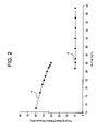
- FIG. 2 is a graph showing pumping mean effective pressure versus air-fuel ratio for a given engine load
- FIG. 3 is a graph illustrating a closed-loop simulation of LNT regeneration in accordance with the invention.
- FIG. 4 is a block diagram showing generally a SIDI engine and engine control hardware in accordance with the invention.
- FIG. 5 is a computer flow chart illustrating a flow of operations for carrying out the control strategy for lean NOx trap regeneration in accordance with the invention
- FIG. 6 is a graph illustrating coordinated engine control for LNT regeneration without the torque compensation of the invention.
- FIG. 7 is a graph illustrating coordinated engine control for LNT regeneration with fueling torque compensation in accordance with the invention.
- An important aspect of the invention addresses the issue that during an LNT regeneration event, the engine must perform increased pumping work due to the increased throttling associated with running rich.
- the invention describes a method to estimate the loss of torque that results due to this increased pumping work and then compensate for this loss by increasing fueling slightly in an amount sufficient to maintain the desired torque level (that is, to effect the step of applying a compensating control torque).
- spark is not preferred as a control variable, since limited torque increase authority is expected through spark adjustment. This concept is illustrated in the diagram of FIG. 1 showing pressure (vertical axis) versus volume (horizontal axis) changes associated with the transition from stratified engine operation to rich homogenous operation during LNT regeneration.
- pressure vertical axis
- volume horizontal axis
- the area denoted as area 1 A represents the combustion work performed by the engine
- area 3 A represents the pumping work.
- the pumping work increases, as illustrated by the expanded area 3 B which includes the pumping work denoted by the area 3 A plus the additional pumping work encompassed by the dotted line 5 .
- the invention contemplates creating combustion work to compensate for the increased pumping work, as illustrated by increasing the combustion work to encompass area 1 B including the combustion work denoted by the area 1 A plus the additional combustion work encompassed by the solid line 7 .
- FIG. 2 the difference in pumping mean effective pressure (PMEP) across a wide range of air-fuel ratios is illustrated for an engine load brake mean effective pressure (BMEP) of substantially 265 kPa.
- Homogenous operation is illustrated by line H for a premixed, lean intake mixture with a swirl index (SI) of 3.3 at 45° C.
- Stratified operation is illustrated by line S for a stratified, lean intake mixture with exhaust gas recirculation (EGR) with an SI of 1.9 at 95° C.
- EGR exhaust gas recirculation
- PMEP is much higher under homogeneous operation than it is under stratified operation for the same air-fuel ratio (e.g. 24–26 air-fuel ratio). This is a consequence of the increased throttling under homogeneous operation.
- the increase in PMEP is about 30 to about 50 kilopascals (kPa) for the illustrated engine load BMEP of 265 kPa.
- V d denotes engine displacement volume
- R denotes the gas constant
- ⁇ ⁇ ⁇ PMEP ⁇ ⁇ ⁇ pumping loop ⁇ P ⁇ ⁇ d V V d ⁇ V d ⁇ ⁇ ⁇ ⁇ P exhaust - V d ⁇ ⁇ ⁇ ⁇ P man V d ⁇ - ⁇ ⁇ ⁇ P man ( 3 )
- This relationship quantifies the increase in PMEP that results from the decrease in MAP due to the increased throttling during NOx regeneration.
- the invention provides compensation for such loss by increasing the torque an amount approximately equal to ⁇ T to maintain the torque desired by the controlling entity (e.g., the driver or a controller such as a cruise controller or idle speed controller).
- the controlling entity e.g., the driver or a controller such as a cruise controller or idle speed controller.
- FIG. 3 shows the benefits of this concept as determined through a closed-loop simulation.
- the simulation results provide air and fuel (in milligrams) ingested into the engine per firing event.
- Columns I and II illustrate the change in engine speed in the RPM row resulting from alternate methods of controlling the engine, including purely air-fuel ratio feedback-based control and constant fueling control.
- Column III illustrates how use of the present control strategy results in minimal change in engine speed throughout the LNT regeneration event.
- FIG. 4 a block diagram showing one possible embodiment of a system for carrying out the present invention includes a spark-ignition direct-injection engine 10 having an air intake 12 for admitting a flow of air into the engine 10 through intake manifold 14 by control of air throttle valves (not shown).
- Electronically-controlled fuel injectors 16 are disposed in the engine 10 for metering fuel thereto. The air-fuel mixtures are then burned in engine cylinders (not shown).
- Exhaust gases produced in the engine cylinder combustion process flow out of the engine cylinders and through one or more exhaust gas conduits 18 .
- a catalytic device such as a three-way converter 20 is connected to the exhaust gas conduit 18 to treat or clean the exhaust gases.
- the exhaust gases pass through a lean NOx trap 22 including two elements 24 and, optionally, a temperature sensor 25 (temperature sensor 25 is not required if code is employed to estimate the LNT temperature).
- An air-fuel ratio sensor 26 such as a post-LNT wide range sensor or a conventional switching-type O 2 sensor, is disposed within the tailpipe 28 for monitoring the concentration of available oxygen in the exhaust gases and providing an output voltage signal POSTO 2 which is received and analyzed by an engine controller 30 .
- the controller 30 is a conventional engine controller including ROM, RAM and CPU and includes a software routine 200 (described in FIG. 3 ) for performing the method of the present invention.
- the controller 30 controls fuel injectors 16 , which inject fuel into their associated cylinders (not shown) in precise quantities and timing as determined by the controller 30 .
- the controller 30 transmits a fuel injector signal to the fuel injectors 16 to maintain an air-fuel ratio determined by the controller including fuel, air, air/fuel ratio, EGR, spark, swirl control valve, and fuel injection timing in accordance with the present control strategy.
- Additional sensors (not shown) provide other information about engine performance to the controller 30 , such as crankshaft position, angular velocity, throttle and air temperature. Additionally, other oxygen sensors 32 variously placed may provide additional control information. The information from these sensors is used by the controller 30 to control engine operation.
- FIG. 5 a flowchart of a software routine 200 for performing the method for controlling a lean burn direct-injection engine during lean NOx trap regeneration in accordance with the invention is shown.
- This routine would be entered periodically from the main engine control software located in engine controller 30 .
- Block 202 indicates the start of the routine for carrying out the present invention, which is performed in the inner control loop of a hierarchical torque-based engine control system with an overall torque command that must be maintained.
- the invention contemplates coordinated control of fuel, air, air/fuel ratio, exhaust gas recirculation, spark, swirl control valve, and fuel injection timing to enable smooth engine operation during lean NOx trap regeneration.
- the estimate of the desired mass of air charge and EGR for the regenerative mode is computed as at block 210 .
- the preferred reference value of manifold absolute pressure is computed.
- the compensating torque feed-forward value sufficient to maintain the base desired torque level during the lean NOx trap regeneration event is computed.
- the compensating torque feed-forward value is added to the predetermined base desired torque as at bock 216 .
- the engine is controlled to operate at the adjusted desired torque (i.e., the base desired torque is maintained by applying the compensating feed-forward torque to offset the loss in braking torque).
- FIGS. 6 and 7 show measured data on this prototype vehicle during a test in which the vehicle was driven at a speed of 70 kph.
- FIG. 6 illustrates selected variables Including throttle pedal position (Pedal position), fueling (Fuel), engine speed (Eng speed), fuel-air equivalence ratio (FA Equiv ratio), and fuel injection timing or fuel pulse angle (FPA).
- Fueling is in grams injected per engine firing event
- engine speed is in RPM
- FPA is in crank angle degrees before top dead center.
- a lean NOx trap regeneration event is initiated just before 111 seconds (time Ti) and ends before 115 seconds (time Te).
- FIG. 6 shows that the engine speed drops by substantially 50 RPM over this event.
- FIG. 7 shows selected variables for a similar lean NOx trap regeneration event while employing the present torque compensation control method.
- FIG. 7 illustrates the improvement that results in terms of a smaller drop in engine speed during the lean NOx trap regeneration event due to the present torque compensation control.
Abstract
Description
prior to and after the LNT regeneration event are known. Therefore, the change in intake manifold pressure (MAP) that would result due to this transition as well, assuming the intake manifold temperature (Tman) and volumetric efficiency ({circumflex over (η)}volumetric efficiency) do not change by the same scale as the change in intake gas charge during this event can readily be estimated. In fact, the control reference value for MAP, denoted by Pref, is given by
where Vd denotes engine displacement volume, and
This relationship quantifies the increase in PMEP that results from the decrease in MAP due to the increased throttling during NOx regeneration.
Claims (18)
Priority Applications (2)
| Application Number | Priority Date | Filing Date | Title |
|---|---|---|---|
| US10/812,466 US7181908B2 (en) | 2004-03-30 | 2004-03-30 | Torque compensation method for controlling a direct-injection engine during regeneration of a lean NOx trap |
| DE102005013280A DE102005013280B4 (en) | 2004-03-30 | 2005-03-22 | Torque compensation method for controlling a direct injection engine during regeneration of lean NOx storage |
Applications Claiming Priority (1)
| Application Number | Priority Date | Filing Date | Title |
|---|---|---|---|
| US10/812,466 US7181908B2 (en) | 2004-03-30 | 2004-03-30 | Torque compensation method for controlling a direct-injection engine during regeneration of a lean NOx trap |
Publications (2)
| Publication Number | Publication Date |
|---|---|
| US20050217246A1 US20050217246A1 (en) | 2005-10-06 |
| US7181908B2 true US7181908B2 (en) | 2007-02-27 |
Family
ID=35052708
Family Applications (1)
| Application Number | Title | Priority Date | Filing Date |
|---|---|---|---|
| US10/812,466 Expired - Fee Related US7181908B2 (en) | 2004-03-30 | 2004-03-30 | Torque compensation method for controlling a direct-injection engine during regeneration of a lean NOx trap |
Country Status (2)
| Country | Link |
|---|---|
| US (1) | US7181908B2 (en) |
| DE (1) | DE102005013280B4 (en) |
Cited By (8)
| Publication number | Priority date | Publication date | Assignee | Title |
|---|---|---|---|---|
| US20080196392A1 (en) * | 2006-12-21 | 2008-08-21 | Stroia Bradlee J | Flexible fuel injection for multiple modes of diesel engine exhaust aftertreatment |
| US20090241899A1 (en) * | 2008-03-26 | 2009-10-01 | Gm Global Technology Operations, Inc. | Reserve Torque for Lean Equivalence Ratio Requests |
| US20090301451A1 (en) * | 2001-03-30 | 2009-12-10 | Toyota Jidosha Kabushiki Kaisha | Control apparatus and method for vehicle having internal combustion engine and continuously variable transmission, and control apparatus and method for internal combustion engine |
| US20100030447A1 (en) * | 2008-08-01 | 2010-02-04 | Gm Global Technology Operations, Inc. | Method to control vehicular powertrain by monitoring map preview information |
| US20100059019A1 (en) * | 2007-08-21 | 2010-03-11 | Toyota Jidosha Kabushiki Kaisha | Control device for internal combustion engine |
| US20140257673A1 (en) * | 2013-03-06 | 2014-09-11 | GM Global Technology Operations LLC | Exhaust gas recirculation control systems and methods |
| US9631567B2 (en) | 2013-08-15 | 2017-04-25 | GM Global Technology Operations LLC | Sensor based measurement and purge control of fuel vapors in internal combustion engines |
| US10066564B2 (en) | 2012-06-07 | 2018-09-04 | GM Global Technology Operations LLC | Humidity determination and compensation systems and methods using an intake oxygen sensor |
Families Citing this family (3)
| Publication number | Priority date | Publication date | Assignee | Title |
|---|---|---|---|---|
| US7401462B2 (en) * | 2004-03-30 | 2008-07-22 | General Motors Corporation | Control strategy for lean NOx trap regeneration |
| US7565892B1 (en) * | 2008-02-01 | 2009-07-28 | Gm Global Technology Operations, Inc. | Method and apparatus for controlling mode transition in a spark-ignition direct-injection internal combustion engine |
| CN116157592A (en) * | 2020-08-27 | 2023-05-23 | 图拉技术公司 | Recharge management for skip cylinders |
Citations (22)
| Publication number | Priority date | Publication date | Assignee | Title |
|---|---|---|---|---|
| US5437153A (en) | 1992-06-12 | 1995-08-01 | Toyota Jidosha Kabushiki Kaisha | Exhaust purification device of internal combustion engine |
| US6041592A (en) | 1996-12-20 | 2000-03-28 | Bayerische Motoren Ag | Control system and method for an NOx accumulator |
| US6065443A (en) | 1998-01-29 | 2000-05-23 | Toyota Jidosha Kabushiki Kaisha | Apparatus and method for controlling combustion in stratified charge combustion engine |
| US6079204A (en) * | 1998-09-21 | 2000-06-27 | Ford Global Technologies, Inc. | Torque control for direct injected engines using a supplemental torque apparatus |
| US6109025A (en) * | 1998-03-17 | 2000-08-29 | Toyota Jidosha Kabushiki Kaisha | Compression ignition type engine |
| US6148612A (en) | 1997-10-13 | 2000-11-21 | Denso Corporation | Engine exhaust gas control system having NOx catalyst |
| US6223525B1 (en) | 1998-06-24 | 2001-05-01 | Honda Giken Kabushiki Kaisha | Air-fuel ratio controlling device for an internal combustion engine |
| US6237329B1 (en) * | 1997-12-25 | 2001-05-29 | Toyota Jidosha Kabushiki Kaisha | Combustion controller for lean burn engines |
| US6244047B1 (en) * | 1998-10-02 | 2001-06-12 | Ford Global Technologies, Inc. | Method of purging lean NOx trap |
| US6253546B1 (en) * | 2000-03-06 | 2001-07-03 | Ford Global Technologies, Inc. | Torque control scheme for low emission lean burn vehicle |
| US6293092B1 (en) | 1999-04-12 | 2001-09-25 | General Motors Corporation | NOx adsorber system regeneration fuel control |
| US6363317B1 (en) * | 2000-08-26 | 2002-03-26 | Ford Global Technologies, Inc. | Calibration method for disc engines |
| US6370868B1 (en) | 2000-04-04 | 2002-04-16 | Ford Global Technologies, Inc. | Method and system for purge cycle management of a lean NOx trap |
| US6539709B2 (en) | 2000-05-02 | 2003-04-01 | Nissan Motor Co., Ltd. | Exhaust gas purifying system of internal combustion engine |
| US6564774B2 (en) * | 2001-04-12 | 2003-05-20 | Dresser, Inc. | Feedforward engine control governing system |
| US6609364B2 (en) * | 1999-07-05 | 2003-08-26 | Volvo Personvagner Ab | Method and arrangement for controlling a combustion engine |
| US6620392B2 (en) | 2000-02-22 | 2003-09-16 | Mazda Motor Corporation | Catalyst for purifying exhaust gas and method for purifying exhaust gas with the catalyst |
| US6708668B2 (en) | 2001-07-17 | 2004-03-23 | Nissan Motor Co., Ltd. | Control system and method for direct-injection spark-ignition engine |
| US6782694B2 (en) | 2002-01-18 | 2004-08-31 | Hitachi, Ltd. | Method and apparatus for controlling an engine |
| US6866610B2 (en) * | 2001-03-30 | 2005-03-15 | Toyota Jidosha Kabushiki Kaisha | Control apparatus and method for vehicle having internal combustion engine and continuously variable transmission, and control apparatus and method for internal combustion engine |
| US7021045B2 (en) * | 2002-11-28 | 2006-04-04 | Isuzu Motors Limited | Fuel injection control device |
| US7051517B2 (en) * | 2003-07-24 | 2006-05-30 | General Motors Corporation | Apparatus and method for electronic throttle control power management enhancements |
Family Cites Families (2)
| Publication number | Priority date | Publication date | Assignee | Title |
|---|---|---|---|---|
| US7401462B2 (en) * | 2004-03-30 | 2008-07-22 | General Motors Corporation | Control strategy for lean NOx trap regeneration |
| US7181902B2 (en) * | 2004-03-30 | 2007-02-27 | General Motors Corporation | Coordinated engine control for lean NOx trap regeneration |
-
2004
- 2004-03-30 US US10/812,466 patent/US7181908B2/en not_active Expired - Fee Related
-
2005
- 2005-03-22 DE DE102005013280A patent/DE102005013280B4/en not_active Expired - Fee Related
Patent Citations (22)
| Publication number | Priority date | Publication date | Assignee | Title |
|---|---|---|---|---|
| US5437153A (en) | 1992-06-12 | 1995-08-01 | Toyota Jidosha Kabushiki Kaisha | Exhaust purification device of internal combustion engine |
| US6041592A (en) | 1996-12-20 | 2000-03-28 | Bayerische Motoren Ag | Control system and method for an NOx accumulator |
| US6148612A (en) | 1997-10-13 | 2000-11-21 | Denso Corporation | Engine exhaust gas control system having NOx catalyst |
| US6237329B1 (en) * | 1997-12-25 | 2001-05-29 | Toyota Jidosha Kabushiki Kaisha | Combustion controller for lean burn engines |
| US6065443A (en) | 1998-01-29 | 2000-05-23 | Toyota Jidosha Kabushiki Kaisha | Apparatus and method for controlling combustion in stratified charge combustion engine |
| US6109025A (en) * | 1998-03-17 | 2000-08-29 | Toyota Jidosha Kabushiki Kaisha | Compression ignition type engine |
| US6223525B1 (en) | 1998-06-24 | 2001-05-01 | Honda Giken Kabushiki Kaisha | Air-fuel ratio controlling device for an internal combustion engine |
| US6079204A (en) * | 1998-09-21 | 2000-06-27 | Ford Global Technologies, Inc. | Torque control for direct injected engines using a supplemental torque apparatus |
| US6244047B1 (en) * | 1998-10-02 | 2001-06-12 | Ford Global Technologies, Inc. | Method of purging lean NOx trap |
| US6293092B1 (en) | 1999-04-12 | 2001-09-25 | General Motors Corporation | NOx adsorber system regeneration fuel control |
| US6609364B2 (en) * | 1999-07-05 | 2003-08-26 | Volvo Personvagner Ab | Method and arrangement for controlling a combustion engine |
| US6620392B2 (en) | 2000-02-22 | 2003-09-16 | Mazda Motor Corporation | Catalyst for purifying exhaust gas and method for purifying exhaust gas with the catalyst |
| US6253546B1 (en) * | 2000-03-06 | 2001-07-03 | Ford Global Technologies, Inc. | Torque control scheme for low emission lean burn vehicle |
| US6370868B1 (en) | 2000-04-04 | 2002-04-16 | Ford Global Technologies, Inc. | Method and system for purge cycle management of a lean NOx trap |
| US6539709B2 (en) | 2000-05-02 | 2003-04-01 | Nissan Motor Co., Ltd. | Exhaust gas purifying system of internal combustion engine |
| US6363317B1 (en) * | 2000-08-26 | 2002-03-26 | Ford Global Technologies, Inc. | Calibration method for disc engines |
| US6866610B2 (en) * | 2001-03-30 | 2005-03-15 | Toyota Jidosha Kabushiki Kaisha | Control apparatus and method for vehicle having internal combustion engine and continuously variable transmission, and control apparatus and method for internal combustion engine |
| US6564774B2 (en) * | 2001-04-12 | 2003-05-20 | Dresser, Inc. | Feedforward engine control governing system |
| US6708668B2 (en) | 2001-07-17 | 2004-03-23 | Nissan Motor Co., Ltd. | Control system and method for direct-injection spark-ignition engine |
| US6782694B2 (en) | 2002-01-18 | 2004-08-31 | Hitachi, Ltd. | Method and apparatus for controlling an engine |
| US7021045B2 (en) * | 2002-11-28 | 2006-04-04 | Isuzu Motors Limited | Fuel injection control device |
| US7051517B2 (en) * | 2003-07-24 | 2006-05-30 | General Motors Corporation | Apparatus and method for electronic throttle control power management enhancements |
Cited By (13)
| Publication number | Priority date | Publication date | Assignee | Title |
|---|---|---|---|---|
| US20090301451A1 (en) * | 2001-03-30 | 2009-12-10 | Toyota Jidosha Kabushiki Kaisha | Control apparatus and method for vehicle having internal combustion engine and continuously variable transmission, and control apparatus and method for internal combustion engine |
| US8256210B2 (en) | 2006-12-21 | 2012-09-04 | Cummins Inc. | Flexible fuel injection for multiple modes of diesel engine exhaust aftertreatment |
| US20080196392A1 (en) * | 2006-12-21 | 2008-08-21 | Stroia Bradlee J | Flexible fuel injection for multiple modes of diesel engine exhaust aftertreatment |
| US20100059019A1 (en) * | 2007-08-21 | 2010-03-11 | Toyota Jidosha Kabushiki Kaisha | Control device for internal combustion engine |
| US8219301B2 (en) * | 2007-08-21 | 2012-07-10 | Toyota Jidosha Kabushiki Kaisha | Control device for internal combustion engine |
| US20090241899A1 (en) * | 2008-03-26 | 2009-10-01 | Gm Global Technology Operations, Inc. | Reserve Torque for Lean Equivalence Ratio Requests |
| US8311721B2 (en) * | 2008-03-26 | 2012-11-13 | GM Global Technology Operations LLC | Reserve torque for lean equivalence ratio requests |
| US20100030447A1 (en) * | 2008-08-01 | 2010-02-04 | Gm Global Technology Operations, Inc. | Method to control vehicular powertrain by monitoring map preview information |
| US8095290B2 (en) | 2008-08-01 | 2012-01-10 | GM Global Technology Operations LLC | Method to control vehicular powertrain by monitoring map preview information |
| US10066564B2 (en) | 2012-06-07 | 2018-09-04 | GM Global Technology Operations LLC | Humidity determination and compensation systems and methods using an intake oxygen sensor |
| US20140257673A1 (en) * | 2013-03-06 | 2014-09-11 | GM Global Technology Operations LLC | Exhaust gas recirculation control systems and methods |
| US9341133B2 (en) * | 2013-03-06 | 2016-05-17 | GM Global Technology Operations LLC | Exhaust gas recirculation control systems and methods |
| US9631567B2 (en) | 2013-08-15 | 2017-04-25 | GM Global Technology Operations LLC | Sensor based measurement and purge control of fuel vapors in internal combustion engines |
Also Published As
| Publication number | Publication date |
|---|---|
| DE102005013280A1 (en) | 2005-10-27 |
| US20050217246A1 (en) | 2005-10-06 |
| DE102005013280B4 (en) | 2008-11-06 |
Similar Documents
| Publication | Publication Date | Title |
|---|---|---|
| US8001767B2 (en) | Engine controller | |
| US7797923B2 (en) | Control strategy for lean NOx trap regeneration | |
| US7089913B2 (en) | Compression ignition internal combustion engine | |
| JP3189734B2 (en) | Spark ignition direct injection internal combustion engine | |
| US6336071B2 (en) | Direct injection engine system and method | |
| US6659073B1 (en) | Method for the operation of a combustion engine | |
| US7181902B2 (en) | Coordinated engine control for lean NOx trap regeneration | |
| EP0879955B1 (en) | Transient control between two spark-ignited combustion states in engine | |
| US7252069B2 (en) | Gas fuel engine and control method for the same | |
| US20040084010A1 (en) | Method and system for controlling combustion mode in an internal combustion engine | |
| JP4918911B2 (en) | Fuel pressure control device for in-cylinder direct fuel injection spark ignition engine | |
| US20110226214A1 (en) | Control Unit for Direct Injection Engine | |
| US6244047B1 (en) | Method of purging lean NOx trap | |
| US7181908B2 (en) | Torque compensation method for controlling a direct-injection engine during regeneration of a lean NOx trap | |
| GB2355494A (en) | Mode transition control in a direct injection i.c.engine system | |
| US7168238B2 (en) | Method for heating up a catalyst in combustion engines with direct fuel injection | |
| US20030226528A1 (en) | Compression ignition internal combustion engine | |
| US20040154585A1 (en) | Method for operating an internal combustion engine especially of a motor vehicle | |
| JP3324039B2 (en) | Method for reducing harmful exhaust emissions of gasoline engines operated with lean fuel-air mixtures | |
| JP2008190511A (en) | Exhaust gas reduction device for direct injection gasoline engine | |
| JP2004507653A (en) | Method and apparatus for heating catalyst in internal combustion engine | |
| CN102787891A (en) | Exhaust purification control device | |
| JP2004507654A (en) | Method for heating catalyst in exhaust gas of internal combustion engine | |
| US6408816B1 (en) | Control apparatus and method for direct-injection spark-ignition internal combustion engine | |
| JP3518366B2 (en) | Engine control device |
Legal Events
| Date | Code | Title | Description |
|---|---|---|---|
| AS | Assignment |
Owner name: GENERAL MOTORS CORPORATION, MICHIGAN Free format text: ASSIGNMENT OF ASSIGNORS INTEREST;ASSIGNOR:NAIK, SANJEEV M.;REEL/FRAME:014581/0438 Effective date: 20040318 |
|
| STCF | Information on status: patent grant |
Free format text: PATENTED CASE |
|
| AS | Assignment |
Owner name: GM GLOBAL TECHNOLOGY OPERATIONS, INC., MICHIGAN Free format text: ASSIGNMENT OF ASSIGNORS INTEREST;ASSIGNOR:GENERAL MOTORS CORPORATION;REEL/FRAME:022102/0533 Effective date: 20050119 Owner name: GM GLOBAL TECHNOLOGY OPERATIONS, INC.,MICHIGAN Free format text: ASSIGNMENT OF ASSIGNORS INTEREST;ASSIGNOR:GENERAL MOTORS CORPORATION;REEL/FRAME:022102/0533 Effective date: 20050119 |
|
| AS | Assignment |
Owner name: UNITED STATES DEPARTMENT OF THE TREASURY, DISTRICT Free format text: SECURITY AGREEMENT;ASSIGNOR:GM GLOBAL TECHNOLOGY OPERATIONS, INC.;REEL/FRAME:022201/0610 Effective date: 20081231 Owner name: UNITED STATES DEPARTMENT OF THE TREASURY,DISTRICT Free format text: SECURITY AGREEMENT;ASSIGNOR:GM GLOBAL TECHNOLOGY OPERATIONS, INC.;REEL/FRAME:022201/0610 Effective date: 20081231 |
|
| AS | Assignment |
Owner name: CITICORP USA, INC. AS AGENT FOR BANK PRIORITY SECU Free format text: SECURITY AGREEMENT;ASSIGNOR:GM GLOBAL TECHNOLOGY OPERATIONS, INC.;REEL/FRAME:022553/0446 Effective date: 20090409 Owner name: CITICORP USA, INC. AS AGENT FOR HEDGE PRIORITY SEC Free format text: SECURITY AGREEMENT;ASSIGNOR:GM GLOBAL TECHNOLOGY OPERATIONS, INC.;REEL/FRAME:022553/0446 Effective date: 20090409 |
|
| AS | Assignment |
Owner name: GM GLOBAL TECHNOLOGY OPERATIONS, INC., MICHIGAN Free format text: RELEASE BY SECURED PARTY;ASSIGNOR:UNITED STATES DEPARTMENT OF THE TREASURY;REEL/FRAME:023124/0429 Effective date: 20090709 Owner name: GM GLOBAL TECHNOLOGY OPERATIONS, INC.,MICHIGAN Free format text: RELEASE BY SECURED PARTY;ASSIGNOR:UNITED STATES DEPARTMENT OF THE TREASURY;REEL/FRAME:023124/0429 Effective date: 20090709 |
|
| AS | Assignment |
Owner name: GM GLOBAL TECHNOLOGY OPERATIONS, INC., MICHIGAN Free format text: RELEASE BY SECURED PARTY;ASSIGNORS:CITICORP USA, INC. AS AGENT FOR BANK PRIORITY SECURED PARTIES;CITICORP USA, INC. AS AGENT FOR HEDGE PRIORITY SECURED PARTIES;REEL/FRAME:023127/0468 Effective date: 20090814 Owner name: GM GLOBAL TECHNOLOGY OPERATIONS, INC.,MICHIGAN Free format text: RELEASE BY SECURED PARTY;ASSIGNORS:CITICORP USA, INC. AS AGENT FOR BANK PRIORITY SECURED PARTIES;CITICORP USA, INC. AS AGENT FOR HEDGE PRIORITY SECURED PARTIES;REEL/FRAME:023127/0468 Effective date: 20090814 |
|
| AS | Assignment |
Owner name: UNITED STATES DEPARTMENT OF THE TREASURY, DISTRICT Free format text: SECURITY AGREEMENT;ASSIGNOR:GM GLOBAL TECHNOLOGY OPERATIONS, INC.;REEL/FRAME:023156/0052 Effective date: 20090710 Owner name: UNITED STATES DEPARTMENT OF THE TREASURY,DISTRICT Free format text: SECURITY AGREEMENT;ASSIGNOR:GM GLOBAL TECHNOLOGY OPERATIONS, INC.;REEL/FRAME:023156/0052 Effective date: 20090710 |
|
| AS | Assignment |
Owner name: UAW RETIREE MEDICAL BENEFITS TRUST, MICHIGAN Free format text: SECURITY AGREEMENT;ASSIGNOR:GM GLOBAL TECHNOLOGY OPERATIONS, INC.;REEL/FRAME:023162/0001 Effective date: 20090710 Owner name: UAW RETIREE MEDICAL BENEFITS TRUST,MICHIGAN Free format text: SECURITY AGREEMENT;ASSIGNOR:GM GLOBAL TECHNOLOGY OPERATIONS, INC.;REEL/FRAME:023162/0001 Effective date: 20090710 |
|
| FPAY | Fee payment |
Year of fee payment: 4 |
|
| AS | Assignment |
Owner name: GM GLOBAL TECHNOLOGY OPERATIONS, INC., MICHIGAN Free format text: RELEASE BY SECURED PARTY;ASSIGNOR:UAW RETIREE MEDICAL BENEFITS TRUST;REEL/FRAME:025311/0770 Effective date: 20101026 Owner name: GM GLOBAL TECHNOLOGY OPERATIONS, INC., MICHIGAN Free format text: RELEASE BY SECURED PARTY;ASSIGNOR:UNITED STATES DEPARTMENT OF THE TREASURY;REEL/FRAME:025245/0442 Effective date: 20100420 |
|
| AS | Assignment |
Owner name: WILMINGTON TRUST COMPANY, DELAWARE Free format text: SECURITY AGREEMENT;ASSIGNOR:GM GLOBAL TECHNOLOGY OPERATIONS, INC.;REEL/FRAME:025327/0001 Effective date: 20101027 |
|
| AS | Assignment |
Owner name: GM GLOBAL TECHNOLOGY OPERATIONS LLC, MICHIGAN Free format text: CHANGE OF NAME;ASSIGNOR:GM GLOBAL TECHNOLOGY OPERATIONS, INC.;REEL/FRAME:025780/0902 Effective date: 20101202 |
|
| FPAY | Fee payment |
Year of fee payment: 8 |
|
| AS | Assignment |
Owner name: GM GLOBAL TECHNOLOGY OPERATIONS LLC, MICHIGAN Free format text: RELEASE BY SECURED PARTY;ASSIGNOR:WILMINGTON TRUST COMPANY;REEL/FRAME:034371/0676 Effective date: 20141017 |
|
| FEPP | Fee payment procedure |
Free format text: MAINTENANCE FEE REMINDER MAILED (ORIGINAL EVENT CODE: REM.); ENTITY STATUS OF PATENT OWNER: LARGE ENTITY |
|
| LAPS | Lapse for failure to pay maintenance fees |
Free format text: PATENT EXPIRED FOR FAILURE TO PAY MAINTENANCE FEES (ORIGINAL EVENT CODE: EXP.); ENTITY STATUS OF PATENT OWNER: LARGE ENTITY |
|
| STCH | Information on status: patent discontinuation |
Free format text: PATENT EXPIRED DUE TO NONPAYMENT OF MAINTENANCE FEES UNDER 37 CFR 1.362 |
|
| FP | Lapsed due to failure to pay maintenance fee |
Effective date: 20190227 |