US7182208B2 - Instrument rack with direct exhaustion - Google Patents
Instrument rack with direct exhaustion Download PDFInfo
- Publication number
- US7182208B2 US7182208B2 US10/741,152 US74115203A US7182208B2 US 7182208 B2 US7182208 B2 US 7182208B2 US 74115203 A US74115203 A US 74115203A US 7182208 B2 US7182208 B2 US 7182208B2
- Authority
- US
- United States
- Prior art keywords
- rack
- air
- electronic devices
- exhaust
- panels
- Prior art date
- Legal status (The legal status is an assumption and is not a legal conclusion. Google has not performed a legal analysis and makes no representation as to the accuracy of the status listed.)
- Expired - Lifetime, expires
Links
- 238000007599 discharging Methods 0.000 claims abstract description 4
- 230000000694 effects Effects 0.000 description 9
- 238000005516 engineering process Methods 0.000 description 8
- 238000001816 cooling Methods 0.000 description 7
- 238000012856 packing Methods 0.000 description 5
- 230000015556 catabolic process Effects 0.000 description 3
- 230000005670 electromagnetic radiation Effects 0.000 description 3
- 239000004020 conductor Substances 0.000 description 2
- 238000000034 method Methods 0.000 description 2
- 239000004033 plastic Substances 0.000 description 2
- 230000002159 abnormal effect Effects 0.000 description 1
- 238000013019 agitation Methods 0.000 description 1
- 230000002547 anomalous effect Effects 0.000 description 1
- 230000003466 anti-cipated effect Effects 0.000 description 1
- 230000002238 attenuated effect Effects 0.000 description 1
- 238000005452 bending Methods 0.000 description 1
- 238000006731 degradation reaction Methods 0.000 description 1
- 230000006866 deterioration Effects 0.000 description 1
- 230000005611 electricity Effects 0.000 description 1
- 230000007613 environmental effect Effects 0.000 description 1
- 239000012212 insulator Substances 0.000 description 1
- 238000012544 monitoring process Methods 0.000 description 1
- 238000005192 partition Methods 0.000 description 1
- 230000000149 penetrating effect Effects 0.000 description 1
- 239000002023 wood Substances 0.000 description 1
Images


Classifications
-
- H—ELECTRICITY
- H05—ELECTRIC TECHNIQUES NOT OTHERWISE PROVIDED FOR
- H05K—PRINTED CIRCUITS; CASINGS OR CONSTRUCTIONAL DETAILS OF ELECTRIC APPARATUS; MANUFACTURE OF ASSEMBLAGES OF ELECTRICAL COMPONENTS
- H05K7/00—Constructional details common to different types of electric apparatus
- H05K7/20—Modifications to facilitate cooling, ventilating, or heating
- H05K7/20536—Modifications to facilitate cooling, ventilating, or heating for racks or cabinets of standardised dimensions, e.g. electronic racks for aircraft or telecommunication equipment
- H05K7/20554—Forced ventilation of a gaseous coolant
- H05K7/20572—Forced ventilation of a gaseous coolant within cabinets for removing heat from sub-racks, e.g. plenum
Definitions
- the present invention relates to a rack for electronic devices and equipments that generate heat and in particular to a low-cost instrument rack with high warm-air discharge efficiency.
- Electronic devices for this type of rack mount are generally equipped with fans that cool each electronic device because when the temperature of each electronic component in the device housing increases too much due to the emission of heat, problems occur in that degradation of the electronic component takes place, and further, its service life is curtailed.
- an instrument rack comprising a rack for mounting devices having two frames (four support columns) arranged parallel to one another in the longitudinal direction at a pre-determined interval and multiple individual electronic devices with fans attached mounted on the frames of this rack lined up in a row in the vertical direction has been used for this type of instrument rack.
- the covers front door, back door, side covers, etc. that are normally attached to the rack are removed and the heat from the electronic devices inside the rack is released to outside of the rack with this type of instrument rack.
- holes that lead to the inside of the rack are made in the top of racks with a cover and the hot air from the electronic devices rises from the bottom of the rack and flows outside the rack through these holes.
- Patent Reference 2 technology is also disclosed in Patent Reference 2 whereby air inflow ports and air outflow ports that open up inside and outside the housing of the electronic devices are set up and in these, the air channel ports of the air ducts communicate with the air inflow ports.
- the exhaust air from the air ducts after the exhaust air from the air ducts has flowed from the air inflow port of the housing into the electronic devices, it flows out again from the air outflow ports of the housing to outside the rack and therefore, the distance for which the exhaust air from the fan passes through the rack is increased and the noise from the exhaust air can be more efficiently attenuated.
- Patent Reference 1 There are problems with the prior technology cited in Patent Reference 1 in that although there is no mixing of intake air and discharge air, since fans for forced air cooling are installed, the suctioning of air is restricted to the bottom of the housing, and there are restrictions to the size and direction of the electronic devices, and the like.
- the present invention is created in light of these foregoing conditions, its object being to improve an instrument rack with which air ducts are placed between the front and back support columns of the rack, the heat discharge efficiency of the electronic devices is improved at a low cost, and the degree of freedom in terms of the size of the rack and placement of electronic devices in the rack is increased.
- the instrument rack of the present invention has a structure in which a rack for holding on its inside multiple electronic devices having intake ports for drawing outside air to inside the devices, exhaust ports for discharging air to outside the devices, and fans, comprising two pairs of support columns, the columns of each pair being placed parallel to one another in the front and the back at a pre-determined distance apart from one another, and with which air ducts for guiding the exhaust air from said exhaust port of each electronic device are positioned between at least one pair of the two support columns.
- the instrument rack further has side covers that cover the side surfaces, and the above-mentioned air ducts are installed between the pair of support columns between the side covers and the inside of the rack and are substantially formed from multiple panels inside the rack.
- the invention herein is a structure in which, by means of the instrument rack, air ducts are positioned between each of the two pairs of support columns. Consequently, the effective cross section of the air ducts is increased and heat discharge efficiency is also increased. Moreover, electronic devices with exhaust ports on any side can be mounted and therefore, power consumption by electronic devices with exhaust ports on both sides is greatly reduced.
- the invention cited herein has a structure in which, by means of the instrument rack with direct exhaustion, there are further telescopic exhaust air ducts between the above-mentioned air exhaust ports and the air ducts in order to guide exhaust air from the exhaust ports to the above-mentioned air ducts. Consequently, differences in the positions of the exhaust ports depending on the electronic device can be assimilated, and therefore, the types of electronic devices that can be mounted without replacing panels that are not needed to adjust each electronic device is increased.
- the invention herein has a structure in which, by means of the instrument rack with direct exhaustion, the exhaust air ducts have packings enclosing the exhaust ports and are joined with the electronic devices by the packings. Consequently, the leakage of exhaust air inside the rack is minimized due to these packings and exhaust air can be more efficiently channeled to the air ducts.
- the invention herein has a structure in which, by means of the instrument rack with direct exhaustion, there are the mentioned exhaust air ducts only at the panels that are adjacent to the exhaust ports of the electronic devices. Consequently, the other panels can be flank panels (flat panels) and therefore, they are inexpensive and it is easy to reduce leakage from the air ducts.
- the invention disclosed herein has a structure in which, by means of the instrument rack with direct exhaustion, the air channel ports of the air ducts are open at the top of the rack. Consequently, the air that has been discharged to the air ducts is more efficiently discharged due to a funnel effect.
- the invention herein has a structure in which, by means of the instrument rack with direct exhaustion, the air channel ports of the air ducts are open at the top of the rack and at the back surface of the rack. Consequently, the air in the air ducts can be efficiently discharged without moving to the adjacent racks.
- the invention herein is the instrument rack with direct exhaustion, wherein the air ducts are positioned on each side surface of the rack. Consequently, discharge is performed by two air ducts and the heat discharge efficiency is improved, and the exhaust ports of the electronic devices can be on either of the side panels, increasing the degree of freedom in terms of selection and placement of the electronic devices.
- the invention herein has a structure in which, by means of the instrument rack with direct exhaustion, the rack has two side covers, a front door, and a back door. Consequently, foreign matter will not enter from the outside and an instrument rack is obtained that is pleasant to look at and with which there is little thermal interference with adjacent racks. Moreover, if the above-mentioned side covers and front and back doors are made from a conductive material, unnecessary electromagnetic radiation from the racks can be easily reduced. For this reason as well, there is little electromagnetic interference with adjacent racks.
- the invention herein has a structure in which, by means of the instrument rack with direct exhaustion, sound absorbing members are attached to the inside of the air ducts. Consequently, the noise from the fans can be further reduced.
- the invention herein has a structure in which, by means of the instrument rack with direct exhaustion, the rack does not have additional fans for forced discharge of the exhaust air inside the air ducts to outside the rack. Consequently, equipment for monitoring fan operation or reporting anomalies is not necessary and there is no anomalous rise in the temperature inside the rack due to breakdown of additional fans. Of course, power for driving the fans is also not necessary. Furthermore, there are no additional fans or electromagnetic radiation through additional fans, so that this solution is effective in reducing unwanted electromagnetic radiation from the rack.
- the invention herein has a structure in which, by means of the instrument rack with direct exhaustion, the electronic devices have intake ports that are different from the exhaust ports and the outside air is drawn from the intake ports by the fans of the intake ports. Consequently, the distance from the fans to the exhaust ports is increased and the amount of noise from the exhaust of the air ducts of the fans is reduced.
- the invention herein has a structure in which, by means of the instrument rack with direct exhaustion structure, the user can select from and install panels having dimensions in the vertical direction that are an integral multiple of the unit length such as one, two, or four times a pre-determined unit length, for instance, 44.45 millimeters.
- a pre-determined unit length for instance, 44.45 millimeters.
- the invention herein of the present invention has a structure in which a rack for holding on its inside multiple electronic devices, which have intake ports for drawing outside air to inside the devices, exhaust ports for discharging air to outside the devices, and fans, comprising two pairs of support columns, the columns of each pair being placed parallel to one another in the front and the back at a pre-determined distance apart from one another, and with which air ducts for guiding the exhaust air from said exhaust port of each electronic device are positioned between at least one pair of said two support columns.
- the rack further has side covers that cover the side surfaces, the above-mentioned air ducts are installed between the above-mentioned pair of support columns between the above-mentioned side covers and the inside of the above-mentioned rack and are substantially formed from multiple panels inside the above-mentioned rack, those ducts comprised of the above-mentioned multiple panels facing the exhaust ports of the electronic devices having an opening and those ducts comprised of the above-mentioned multiple panels facing the intake ports of the electronic devices not having an opening, and there is a space between the above-mentioned panels and the above-mentioned intake ports so that air can flow in from the above-mentioned intake ports and air is discharged from the above-mentioned openings through the above-mentioned air ducts.
- FIG. 1 is a perspective view showing the instrument rack of an embodiment of the present invention from the front side.
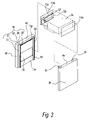
- FIG. 2 is a perspective view showing the inside of the instrument rack of an embodiment of the present invention from the back side.
- FIG. 3 is a perspective view showing the instrument rack of an embodiment of the present invention from the front side.
- FIG. 4 is a perspective view showing the instrument rack of an embodiment of the present invention from the front side.
- FIG. 5 is a perspective view showing the instrument rack of an embodiment of the present invention from the back side.
- FIG. 1 is an oblique view showing the instrument rack of one embodiment of the present invention and shows the state where the electronic devices are mounted and the front door is removed to see inside.
- FIG. 2 is an oblique view showing the same instrument rack of one embodiment of the present invention in the same state as in FIG. 1 , but it is a drawing seen from the back with the mounted electronic devices removed.
- the entire unit, including the electronic devices represented by symbol 1 , in FIGS. 1 and 2 comprises the instrument rack (referred to below as the “rack”) having air ducts 4 and electronic devices 3 .
- Rack 2 in FIGS. 1 and 2 has support columns 5 ( 5 a , 5 b , 5 c (not illustrated), 5 d ), top plate 6 , base plate 7 , and side covers 8 ( 8 a , 8 b ), and preferably the entire unit is formed to meet standard dimensions.
- the side covers form the sides of air ducts 4 ( 4 a , 4 b ) and that the air that is discharged to the air ducts by the fans of electronic devices 3 is discharged from opening 14 ( 14 a , 14 b ) made extending to the top of air ducts 4 to outside the rack in the direction of arrows Z.
- Opening 14 is preferably a group of many small holes.
- Support columns 5 comprise one pair of front support columns 5 a and 5 b , each of which are placed parallel to one another on the left and the right at a pre-determined distance apart from one another, and one pair of back support columns 5 c and 5 d (back support column 5 c is not illustrated), each of which are placed parallel to the respective front support column 5 a and 5 b at a pre-determined distance apart from one another. They are placed standing on base plate 7 .
- support columns 5 a through 5 d can have the same cross section, for instance, an ⁇ -shape with 5 sides. They have two foot parts, two leg parts, and one head part. They are placed so that the heads of the front support columns face one another and the heads of the back support columns face one another, with the foot parts toward the outside of the rack.
- top side beams (not illustrated) that connect front support columns 5 a and 5 b and back support columns 5 c and 5 d at the top are supported at the top end of support column 5 .
- the bottom side beams (only bottom beams 5 e is illustrated) that connect front support columns 5 a and 5 b and back support columns 5 c and 5 d at the bottom are supported at the bottom end of support column 5 .
- Top plate 6 is placed at the top of rack 2 and is fastened to the top side beam.
- Base plate 7 is placed at the bottom of rack 2 and is fastened to bottom side beam 5 e .
- Side covers 8 are positioned on both sides of rack 2 and are fastened to support columns 5 a through 5 d and side beam 5 e , etc. Side covers 8 can also be fastened to support columns 5 .
- Fastener parts 9 having many screw holes or through holes 9 a , and the like are made in a vertical row at pre-determined distances in each support column 5 a through 5 d .
- multiple electronic devices 3 and panels 11 11 a through 11 g ) are fastened at specific intervals running up and down the rack to support columns 5 of rack 2 .
- the conventional fastening angles for fastening electronic devices 3 to support columns 5 are omitted in FIG. 1 .
- support column 5 with an ⁇ -shaped cross section has foot parts that project between the support columns at the side of the rack.
- panels 11 can be fastened to this second fastener part.
- Electronic devices are fastened to the support columns by the head part of the ⁇ shaped cross section.
- Panels 11 are described as being the same type as used for side covers 8 a and 8 b , but it is obvious that the effects of the present invention can be realized with other types of panels.
- each cross section of support columns 5 a through 5 d is a shape in which one projecting foot part is missing
- the support columns are positioned so that the head parts of the front support columns and the back support columns face the side surfaces of the rack from opposing directions.
- the electronic devices are fastened using an angle to the leg part that is missing this foot part and panel 11 is fastened to the foot part.
- the leg part with the foot part preferably comprises part of the wall of air duct 4 without holes.
- panel 11 can be present in only two types, square blank panels and panels with exhaust ducts that are the same length (dimension in the horizontal direction when mounted on the rack) and the same width (dimension in the vertical direction when mounted on the rack).
- Several types of panels that come in widths that are a multiple of the standardized height of the electronic devices can also be used. For instance, in the examples, when 1 unit is 44.45 millimeters based on EIA standards, panels whose dimensions are 1 unit, 2 units and 4 units are each used. Thus, the appropriate panel should be selected and attached in accordance with the height of the electronic devices that are being housed.
- many panels of two types (with and without ducts) of a minimum standardized height are used.
- the examples of the present invention are easy to handle and inexpensive.
- the bottom side of the top panels overlap the top side of the adjacent bottom panel from the inside of the rack.
- the bottom sides of the panels should be worked so that they will move horizontally by a distance that corresponds to the panel thickness of a dimension of several mm to 1 cm.
- panels 11 c through 11 g that do not face the exhaust ports of the electronic devices are blank panels (panels that have no holes other than fastener holes).
- panels 11 a and 11 b that face the exhaust ports have exhaust ducts 12 a and 12 b , respectively, which are connected to the exhaust ports.
- the bases of exhaust ducts 12 a and 12 b are anchored in place by being fastened to the openings in panels 11 a and 11 b and the top parts of exhaust ducts 12 a and 12 b are connected to the exhaust ports so that they can be disconnected again as needed.
- the side of the electronic devices without fans generally faces a blank panel, but when this side is the same side as the exhaust port, it should face a panel with an exhaust duct.
- Each panel 11 is preferably fastened to support column 5 using a latch-type fastener. Consequently, it is possible to attach and detach panel 11 manually without using tools. Of course, the remaining results of the present invention are obtained also when the panels are fastened with screws.
- air duct 4 a is made so that it is substantially formed by side cover 8 a and panels 11 a through 11 g and exhaust air from electronic devices 3 a and 3 b that has entered from the exhaust port through exhaust ducts 12 a and 12 b , shown in FIG. 2 , is discharged through openings 14 a and 14 c to outside the rack.
- air duct 4 b at the side of side cover 8 b has the same structure as air duct 4 a , as shown in FIG. 2 .
- Electronic device group 3 comprises multiple electronic devices 3 a , 3 b , 3 c , and 3 d that are lined up in a vertical row and is housed mounted inside rack 2 using mounting tools 30 a and 30 b and fastening angles (not illustrated), and is anchored to top support columns 5 a and 5 b .
- These electronic devices have intake ports and exhaust ports for air on the side of the side covers. The case in which electronic devices 3 a and 3 b have exhaust ports on the side of side cover 8 a will be described. It should be noted that the vertical placement of the electronic devices is not limited to what is illustrated.
- Electronic devices 3 a and 3 b have a cooling fan on the side of the exhaust port to the left in the figure. Moreover, it is also possible for a fan to draw air inside the rack through an intake port with an appropriate filter into electronic devices 3 a and 3 b and discharge the air through the exhaust port without placing a fan at the exhaust port.
- the air inside the rack is drawn from outside rack 2 through small spaces 8 ca , 8 da , and the like of front door 8 c and rear door 8 d . There is sufficient space made between the panels on the side of the intake ports of electronic devices 3 a and 3 b and the intake ports, and therefore, air is drawn through these spaces to the intake ports.
- exhaust ports of the electronic devices can be on the left side or the right side of the drawings, and the panels facing the exhaust ports should be the panels with openings and the panels not facing the exhaust ports should be the blank panels.
- FIG. 3 is an oblique view of the structure in FIG. 1 cut into two horizontal planes and includes the segment from part of panel 11 e to part of panel 11 g .
- Electronic device 3 e is mounted and has an exhaust port at the surface that faces the side of rack 2 .
- Support columns 5 a through 5 d will be described as having an ⁇ -shaped cross section. It should be noted that this cross section can have a variety of shapes in accordance with the object of the present invention. Although support columns 5 a through 5 d have the same cross section, only support column 5 b will be described.
- the cross section of support column 5 b is ⁇ -shaped and in accordance with this cross section, the support column has a first foot part 52 and a second foot part 54 , first and second leg parts 51 and 55 , and a head part 53 .
- Side cover 8 b can be fastened to foot part 52 , or it can simply be fastened to the side wood piece at the top or the bottom of the support column so that the foot part is covered by the side cover.
- panels 11 f which are flat sheets without exhaust ducts and correspond to the position where electronic device 3 e should be mounted, are removed.
- panels 11 fa with exhaust ducts 12 f are instead attached between support columns 5 a and 5 c and support columns 5 b and 5 d , respectively, of the rack using screws, or preferably latch-type fasteners.
- the base of exhaust duct 12 f is screwed into place or adhered to panel 11 fa so that opening 13 a in panel 11 fa is enclosed inside exhaust duct 12 f.
- the head part of exhaust duct 12 f encloses the exhaust port of electronic device 3 e fitting closely to the side of electronic device 3 e so that all of the exhaust air from this exhaust port is drawn into the exhaust duct.
- flexible packing 13 b made of rubber or plastic can be fastened to the head part of exhaust duct 12 f .
- Packing 13 b can absorbs slips in position in the horizontal direction of electronic device 3 e , and therefore, it provides the effect of easily being able to use exhaust duct 12 f with electronic devices of different sizes in the horizontal direction.
- using an exhaust duct 12 f that is bellows-shaped can also further increase the degree of freedom in the direction of length.
- electronic devices of different widths can be easily accommodated by applying spring force to the bellows-shaped exhaust duct in the direction in which it expands by means of a coil spring, and the like.
- FIGS. 4 and 5 are oblique views seen from outside rack 2 of the instrument rack of the present invention with front door 8 c and back door 8 d .
- Front door 8 c is shown in FIG. 4 . It has a structure with many long small spaces 8 ca that join the inside and the outside of the rack so that outside air is drawn into the rack.
- back door 8 d is shown in FIG. 5 . It has a structure with many short small spaces 8 da that join the inside and the outside of the rack so that outside air can also be drawn into the rack.
- the arrows in FIGS. 4 and 5 show the direction in which air flows.
- Side covers 8 a and 8 b , front door 8 c , back door 8 d , and the like can be made from an insulator, such as plastic, etc., but if they are made from a conductor, unwanted electromagnetic energy that radiates from rack 2 of cooled structure 1 to the environment is reduced.
- each air duct 4 a and 4 b is common to all electronic devices was described, but each individual electronic device or groups of electronic devices can also be discharged by bending the top side of panel 11 to inside the air duct and setting up partitions in panel 11 so that exhaust air is discharged to openings 14 c and 14 d in the back surface.
- the rack dimensions can be reduced in the direction of length.
- this embodiment describes the case where air duct 4 simply functions as a unit that serves to guide exhaust air from the exhaust port to outside rack 2 .
- the present invention is not limited to this embodiment and it is also possible to absorb part of the noise generated by the exhaust air by affixing a sound-absorbing member (not illustrated) inside air duct 4 , as with the prior art.
- air ducts for guiding exhaust air from each electronic device to outside the rack are positioned between both the front and the back support columns, and therefore, when each fan draws outside air to inside the devices, this air passes through these devices, and exhaust air is discharged to outside the devices, so that this exhaust air is directed to outside the rack by air ducts without entering inside the rack.
Abstract
Description
Claims (6)
Applications Claiming Priority (2)
| Application Number | Priority Date | Filing Date | Title |
|---|---|---|---|
| JP2002370409A JP2004200594A (en) | 2002-12-20 | 2002-12-20 | System rack having exhaust structure |
| JP2002-370409 | 2002-12-20 |
Publications (2)
| Publication Number | Publication Date |
|---|---|
| US20040182799A1 US20040182799A1 (en) | 2004-09-23 |
| US7182208B2 true US7182208B2 (en) | 2007-02-27 |
Family
ID=32766344
Family Applications (1)
| Application Number | Title | Priority Date | Filing Date |
|---|---|---|---|
| US10/741,152 Expired - Lifetime US7182208B2 (en) | 2002-12-20 | 2003-12-19 | Instrument rack with direct exhaustion |
Country Status (3)
| Country | Link |
|---|---|
| US (1) | US7182208B2 (en) |
| JP (1) | JP2004200594A (en) |
| DE (1) | DE10360407A1 (en) |
Cited By (50)
| Publication number | Priority date | Publication date | Assignee | Title |
|---|---|---|---|---|
| US20070171610A1 (en) * | 2006-01-20 | 2007-07-26 | Chatsworth Products, Inc. | Internal air duct |
| US20070211428A1 (en) * | 2006-03-08 | 2007-09-13 | Cray Inc. | Multi-stage air movers for cooling computer systems and for other uses |
| US20070223191A1 (en) * | 2006-03-24 | 2007-09-27 | Fujitsu Limited | Electronic apparatus |
| US20070223201A1 (en) * | 2006-03-24 | 2007-09-27 | Fujitsu Limited | Electronic apparatus |
| US20070258211A1 (en) * | 2004-11-16 | 2007-11-08 | Fujitsu Limited | Communication apparatus and rack structure |
| US20080035810A1 (en) * | 2006-08-12 | 2008-02-14 | Chatsworth Products, Inc. | Offset brackets for expanding electronic equipment cabinets |
| US7443674B1 (en) * | 2007-06-25 | 2008-10-28 | Hanlon Thomas | Rack enclosure cooling system |
| US20080285232A1 (en) * | 2007-05-17 | 2008-11-20 | International Business Machines Corporation | Techniques for Data Center Cooling |
| US20080288193A1 (en) * | 2007-05-17 | 2008-11-20 | International Business Machines Corporation | Techniques for Analyzing Data Center Energy Utilization Practices |
| US20080316702A1 (en) * | 2007-05-17 | 2008-12-25 | Chatsworth Products, Inc. | Exhaust air duct with adjustable filler panel assemblies |
| US20090059523A1 (en) * | 2007-08-30 | 2009-03-05 | Michael Mallia | Cabinet for electronic equipment |
| US20090056910A1 (en) * | 2007-08-30 | 2009-03-05 | Paul Mallia | Fluid cooled cabinet for electronic equipment |
| US20090086434A1 (en) * | 2007-09-30 | 2009-04-02 | Marc Hodes | Recirculating Gas Rack Cooling Architecture |
| US20090154091A1 (en) * | 2007-12-17 | 2009-06-18 | Yatskov Alexander I | Cooling systems and heat exchangers for cooling computer components |
| US20090190307A1 (en) * | 2005-09-19 | 2009-07-30 | Chatsworth Products, Inc. | Ducted exhaust equipment enclosure |
| US20090201644A1 (en) * | 2008-02-11 | 2009-08-13 | Kelley Douglas P | Systems and associated methods for cooling computer components |
| US7586745B1 (en) * | 2006-03-01 | 2009-09-08 | Network Appliance, Inc. | Unique airflow path using fungible chassis components |
| US20090227197A1 (en) * | 2008-02-14 | 2009-09-10 | Chatsworth Products, Inc. | Air directing device |
| US20090239461A1 (en) * | 2005-09-19 | 2009-09-24 | Chatsworth Products, Inc. | Air diverter for directing air upwardly in an equipment enclosure |
| US20090244826A1 (en) * | 2008-04-01 | 2009-10-01 | Doll Wade J | Airflow management apparatus for computer cabinets and associated methods |
| US20090268391A1 (en) * | 2008-04-28 | 2009-10-29 | Hitachi. Ltd | Disk array device and electronic device |
| US20100003911A1 (en) * | 2008-06-19 | 2010-01-07 | Panduit Corp. | Passive Cooling Systems for Network Cabinet |
| US7646602B1 (en) | 2008-08-29 | 2010-01-12 | Qlogic, Corporation | Apparatus and methods for cooling network switches |
| US20100056036A1 (en) * | 2008-09-03 | 2010-03-04 | International Business Machines Corporation | Noise-reducing side chambers for air exhaust from computer racks and a method of exhausting air and reducing noise by using the same |
| US7675750B1 (en) * | 2008-08-29 | 2010-03-09 | Qlogic, Corporation | Apparatus and methods for cooling networks switches |
| US20100061059A1 (en) * | 2005-09-19 | 2010-03-11 | Chatsworth Products, Inc. | Ducted exhaust equipment enclosure |
| US20100097751A1 (en) * | 2008-10-17 | 2010-04-22 | Doll Wade J | Air conditioning systems for computer systems and associated methods |
| US20100097752A1 (en) * | 2008-10-17 | 2010-04-22 | Doll Wade J | Airflow intake systems and associated methods for use with computer cabinets |
| US20100172093A1 (en) * | 2009-01-05 | 2010-07-08 | Chatsworth Products, Inc. | Electronic equipment enclosure with side-to-side airflow control system |
| US20100213803A1 (en) * | 2006-12-12 | 2010-08-26 | Rittal Gmbh & Co.Kg | Control box arrangement |
| US20100315788A1 (en) * | 2009-06-16 | 2010-12-16 | Brocade Communications Systems, Inc | Side-exhaust cooling system for rack mounted equipment |
| US20110096498A1 (en) * | 2007-09-25 | 2011-04-28 | Blade Network Technologies, Inc. | Apparatus for externally changing the direction of air flowing through electronic equipment |
| US7974105B2 (en) | 2008-01-07 | 2011-07-05 | Chatsworth Products, Inc. | Apparatus and method for organizing cables in a cabinet |
| US20110292603A1 (en) * | 2010-06-01 | 2011-12-01 | International Business Machines Corporation | Airflow control apparatus |
| US8144464B2 (en) * | 2010-04-29 | 2012-03-27 | Brocade Communication Systems, Inc. | Side-exhaust cooling system with extensible duct for rack mounted equipment |
| US20120134111A1 (en) * | 2010-11-25 | 2012-05-31 | Hon Hai Precision Industry Co., Ltd. | Server cabinet and server system utilizing the same |
| US8257155B2 (en) | 2006-01-20 | 2012-09-04 | Chatsworth Products, Inc. | Selectively routing air within an electronic equipment enclosure |
| US20130088833A1 (en) * | 2011-10-05 | 2013-04-11 | International Business Machines Corporation | Flexible air duct for equipment cooling |
| US8472181B2 (en) | 2010-04-20 | 2013-06-25 | Cray Inc. | Computer cabinets having progressive air velocity cooling systems and associated methods of manufacture and use |
| US8582292B1 (en) * | 2010-12-27 | 2013-11-12 | Amazon Technologies, Inc. | Integrated ventilation system for electronic equipment |
| US8653363B2 (en) | 2010-06-01 | 2014-02-18 | Chatsworth Products, Inc. | Magnetic filler panel for use in airflow control system in electronic equipment enclosure |
| US8687363B2 (en) * | 2012-05-01 | 2014-04-01 | General Electric Company | Enclosure with duct mounted electronic components |
| US20140159552A1 (en) * | 2012-12-11 | 2014-06-12 | Panduit Corp. | Equipment Segregation Unit For An Industrial Control Panel |
| US20160105993A1 (en) * | 2014-01-23 | 2016-04-14 | Huawei Technologies Co., Ltd. | Air Deflection System |
| US9549480B1 (en) * | 2015-10-23 | 2017-01-17 | International Business Machines Corporation | Configurable door panels |
| US9655259B2 (en) | 2011-12-09 | 2017-05-16 | Chatsworth Products, Inc. | Data processing equipment structure |
| EP3292745A4 (en) * | 2015-05-07 | 2019-04-03 | DHK Storage LLC | Computer server heat regulation utilizing integrated precision air flow |
| US10524394B2 (en) | 2017-05-08 | 2019-12-31 | Panduit Corp. | 4-post rack with integrated intake/exhaust regions |
| US11212928B2 (en) | 2005-09-19 | 2021-12-28 | Chatsworth Products, Inc. | Vertical exhaust duct for electronic equipment enclosure |
| US11259446B2 (en) | 2005-09-19 | 2022-02-22 | Chatsworth Products, Inc. | Vertical exhaust duct for electronic equipment enclosure |
Families Citing this family (25)
| Publication number | Priority date | Publication date | Assignee | Title |
|---|---|---|---|---|
| DE102005017770A1 (en) * | 2005-04-13 | 2006-10-26 | Siemens Ag | Cabinet for accommodating electrical component in rail vehicle, has mounting plates arranged parallel to walls, and upper and lower openable air way formed in walls of cabinet at rear side of plates, where circulating air flows via air way |
| JP4594189B2 (en) * | 2005-08-08 | 2010-12-08 | 富士通株式会社 | Heating element cooling device |
| US20070064389A1 (en) * | 2005-09-19 | 2007-03-22 | Chatsworth Products, Inc. | Ducted exhaust equipment enclosure |
| US8079481B2 (en) * | 2005-10-28 | 2011-12-20 | International Business Machines Corporation | Integrated frame and central electronic complex structure |
| JP4935443B2 (en) * | 2007-03-19 | 2012-05-23 | 株式会社日立製作所 | Sound absorption structure of electronic equipment |
| US7764495B2 (en) * | 2007-04-30 | 2010-07-27 | Adc Telecommunications, Inc. | Telecommunication cabinet with airflow ducting |
| JP2008294255A (en) * | 2007-05-25 | 2008-12-04 | Kawamura Electric Inc | Cabinet rack |
| US7611270B1 (en) * | 2007-09-07 | 2009-11-03 | Whelen Engineering Company, Inc. | Lighthead mounting structure |
| JP2009147109A (en) * | 2007-12-14 | 2009-07-02 | Nitto Electric Works Ltd | Box for housing electric and electronic apparatus |
| JP5605982B2 (en) * | 2008-05-15 | 2014-10-15 | 高砂熱学工業株式会社 | Ventilation device and air conditioning ventilation system |
| JP2011089716A (en) * | 2009-10-23 | 2011-05-06 | Takasago Thermal Eng Co Ltd | Air conditioning system and hood device |
| TW201127250A (en) * | 2010-01-22 | 2011-08-01 | Hon Hai Prec Ind Co Ltd | Section bar and rack enclosure using the same |
| DE102010000243B4 (en) * | 2010-01-28 | 2011-11-03 | Rittal Gmbh & Co. Kg | switch cabinet |
| US8952252B2 (en) | 2010-10-22 | 2015-02-10 | Rockwell Automation Technologies, Inc. | Arc resistant electrical enclosure |
| DE102011005838A1 (en) * | 2011-03-21 | 2012-09-27 | Siemens Aktiengesellschaft | Device for actively venting internals of a drawer of a control cabinet |
| EP2503257B9 (en) * | 2011-03-22 | 2014-06-04 | Erwin Gasser | Shelter |
| JP5201611B2 (en) * | 2011-05-25 | 2013-06-05 | エヌイーシーコンピュータテクノ株式会社 | Electronic equipment cooling structure |
| JP5842695B2 (en) * | 2012-03-21 | 2016-01-13 | 日本電気株式会社 | Rack for electronic equipment |
| US20140036442A1 (en) * | 2012-07-31 | 2014-02-06 | Alcatel-Lucent Deutschland Ag | Outdoor stackable telecommunications equipment cabinet family with flexible thermal and interface management and method of deploying the same |
| US9038831B2 (en) * | 2012-11-27 | 2015-05-26 | Oracle International Corporation | Disaster resistant system for maintaining operation of computing devices mounted within storage racks during water and other related contaminating events |
| WO2016167804A1 (en) * | 2015-04-17 | 2016-10-20 | Hewlett Packard Enterprise Development Lp | Rack enclosure with perforations for cooling |
| DE102016100640A1 (en) * | 2016-01-15 | 2017-07-20 | Avl Emission Test Systems Gmbh | Control cabinet for exhaust gas measuring systems |
| US9955607B1 (en) * | 2016-12-21 | 2018-04-24 | Mountain Stone Technologies, LLC | Electronic equipment vertical mount and stack rack |
| JP7306663B2 (en) * | 2017-06-02 | 2023-07-11 | Necプラットフォームズ株式会社 | storage rack |
| CN111601482A (en) * | 2020-05-30 | 2020-08-28 | 戴文文 | Cloud computing server platform based on big data |
Citations (25)
| Publication number | Priority date | Publication date | Assignee | Title |
|---|---|---|---|---|
| DE1011936B (en) | 1956-03-21 | 1957-07-11 | Siemens Ag | Device for ventilating racks in electrical communications and measurement technology |
| US3192306A (en) | 1962-09-26 | 1965-06-29 | Philco Corp | Cooling wall structure for electronic equipment cabinet |
| FR2193303A1 (en) | 1972-07-24 | 1974-02-15 | Merlin Gerin | |
| DE2537295A1 (en) | 1974-08-29 | 1976-04-22 | Cselt Centro Studi Lab Telecom | Electronic cabinet bank centrally driven air cooling - provides one general air supply to entire cabinet and allows individual tray treatment (SW290376) |
| DE3316978A1 (en) | 1983-05-09 | 1984-11-15 | Siemens AG, 1000 Berlin und 8000 München | Construction system for dissipating the heat losses from electronic assemblies which are arranged in containers or cabinets |
| US4528614A (en) | 1983-10-07 | 1985-07-09 | Westinghouse Electric Corp. | Electric control center having integral air-ventilation system |
| JPS62174397A (en) | 1986-01-28 | 1987-07-31 | Nippon Steel Corp | Thin sn plated steel sheet for container having excellent corrosion resistance and weldability |
| US4797783A (en) * | 1984-09-26 | 1989-01-10 | Nec Corporation | Air cooling equipment for electronic systems |
| US5216579A (en) | 1992-01-29 | 1993-06-01 | International Business Machines Corporation | Rack based packaging system for computers with cable, cooling and power management module |
| US5493474A (en) * | 1995-02-14 | 1996-02-20 | Hewlett-Packard Company | Enclosure with redundant air moving system |
| DE29718687U1 (en) | 1997-10-22 | 1997-12-11 | Schaefer Werke Gmbh | Metal sheet cabinet |
| US5782546A (en) * | 1996-04-10 | 1998-07-21 | Nec Corporation | Door structure for cabinets |
| US5818696A (en) * | 1994-03-14 | 1998-10-06 | Siemens Nixdorf Informationssysteme Aktiengesellschaft | Mounting panel for assemblies |
| DE19804905A1 (en) | 1998-02-07 | 1999-08-19 | Loh Kg Rittal Werk | switch cabinet |
| DE19804902A1 (en) | 1998-02-07 | 1999-08-19 | Loh Kg Rittal Werk | switch cabinet |
| JP2000277956A (en) | 1999-03-29 | 2000-10-06 | Nec Corp | Cooling structure of electronic unit for rack mounting |
| DE20016013U1 (en) | 2000-09-15 | 2001-11-08 | Siemens Ag | Control cabinet with improved heat dissipation |
| US6462944B1 (en) * | 2000-10-25 | 2002-10-08 | Macase Industrial Group Ga., Inc. | Computer cabinet cooling system |
| US6463997B1 (en) * | 1998-02-07 | 2002-10-15 | Rittal-Werk Rudolf Loh Gmbh & Co. Kg | Control cabinet with air conditioning device |
| DE10121759A1 (en) | 2001-05-04 | 2002-11-14 | Siemens Ag | Equipment cabinet e.g. for electrical or electronic modules or appliances, uses separation seam as duct for extraction of waste heat |
| DE10128367A1 (en) | 2001-06-12 | 2003-01-02 | Fujitsu Siemens Computers Gmbh | Computer cabinet and arrangement of a computer cabinet |
| US6643123B2 (en) * | 2001-07-26 | 2003-11-04 | Rittal Gmbh & Co. Kg | Switchgear cabinet with at least one cabinet door and a fan-assisted air circulation on an interior |
| EP1389900A2 (en) | 2002-08-12 | 2004-02-18 | Motorola, Inc. | Cabinet for cooling electronic modules |
| US6776707B2 (en) * | 1998-12-30 | 2004-08-17 | Engineering Equipment And Services, Inc. | Computer cabinet |
| US6877551B2 (en) * | 2002-07-11 | 2005-04-12 | Avaya Technology Corp. | Systems and methods for weatherproof cabinets with variably cooled compartments |
-
2002
- 2002-12-20 JP JP2002370409A patent/JP2004200594A/en active Pending
-
2003
- 2003-12-19 US US10/741,152 patent/US7182208B2/en not_active Expired - Lifetime
- 2003-12-19 DE DE10360407A patent/DE10360407A1/en not_active Withdrawn
Patent Citations (25)
| Publication number | Priority date | Publication date | Assignee | Title |
|---|---|---|---|---|
| DE1011936B (en) | 1956-03-21 | 1957-07-11 | Siemens Ag | Device for ventilating racks in electrical communications and measurement technology |
| US3192306A (en) | 1962-09-26 | 1965-06-29 | Philco Corp | Cooling wall structure for electronic equipment cabinet |
| FR2193303A1 (en) | 1972-07-24 | 1974-02-15 | Merlin Gerin | |
| DE2537295A1 (en) | 1974-08-29 | 1976-04-22 | Cselt Centro Studi Lab Telecom | Electronic cabinet bank centrally driven air cooling - provides one general air supply to entire cabinet and allows individual tray treatment (SW290376) |
| DE3316978A1 (en) | 1983-05-09 | 1984-11-15 | Siemens AG, 1000 Berlin und 8000 München | Construction system for dissipating the heat losses from electronic assemblies which are arranged in containers or cabinets |
| US4528614A (en) | 1983-10-07 | 1985-07-09 | Westinghouse Electric Corp. | Electric control center having integral air-ventilation system |
| US4797783A (en) * | 1984-09-26 | 1989-01-10 | Nec Corporation | Air cooling equipment for electronic systems |
| JPS62174397A (en) | 1986-01-28 | 1987-07-31 | Nippon Steel Corp | Thin sn plated steel sheet for container having excellent corrosion resistance and weldability |
| US5216579A (en) | 1992-01-29 | 1993-06-01 | International Business Machines Corporation | Rack based packaging system for computers with cable, cooling and power management module |
| US5818696A (en) * | 1994-03-14 | 1998-10-06 | Siemens Nixdorf Informationssysteme Aktiengesellschaft | Mounting panel for assemblies |
| US5493474A (en) * | 1995-02-14 | 1996-02-20 | Hewlett-Packard Company | Enclosure with redundant air moving system |
| US5782546A (en) * | 1996-04-10 | 1998-07-21 | Nec Corporation | Door structure for cabinets |
| DE29718687U1 (en) | 1997-10-22 | 1997-12-11 | Schaefer Werke Gmbh | Metal sheet cabinet |
| US6463997B1 (en) * | 1998-02-07 | 2002-10-15 | Rittal-Werk Rudolf Loh Gmbh & Co. Kg | Control cabinet with air conditioning device |
| DE19804905A1 (en) | 1998-02-07 | 1999-08-19 | Loh Kg Rittal Werk | switch cabinet |
| DE19804902A1 (en) | 1998-02-07 | 1999-08-19 | Loh Kg Rittal Werk | switch cabinet |
| US6776707B2 (en) * | 1998-12-30 | 2004-08-17 | Engineering Equipment And Services, Inc. | Computer cabinet |
| JP2000277956A (en) | 1999-03-29 | 2000-10-06 | Nec Corp | Cooling structure of electronic unit for rack mounting |
| DE20016013U1 (en) | 2000-09-15 | 2001-11-08 | Siemens Ag | Control cabinet with improved heat dissipation |
| US6462944B1 (en) * | 2000-10-25 | 2002-10-08 | Macase Industrial Group Ga., Inc. | Computer cabinet cooling system |
| DE10121759A1 (en) | 2001-05-04 | 2002-11-14 | Siemens Ag | Equipment cabinet e.g. for electrical or electronic modules or appliances, uses separation seam as duct for extraction of waste heat |
| DE10128367A1 (en) | 2001-06-12 | 2003-01-02 | Fujitsu Siemens Computers Gmbh | Computer cabinet and arrangement of a computer cabinet |
| US6643123B2 (en) * | 2001-07-26 | 2003-11-04 | Rittal Gmbh & Co. Kg | Switchgear cabinet with at least one cabinet door and a fan-assisted air circulation on an interior |
| US6877551B2 (en) * | 2002-07-11 | 2005-04-12 | Avaya Technology Corp. | Systems and methods for weatherproof cabinets with variably cooled compartments |
| EP1389900A2 (en) | 2002-08-12 | 2004-02-18 | Motorola, Inc. | Cabinet for cooling electronic modules |
Cited By (132)
| Publication number | Priority date | Publication date | Assignee | Title |
|---|---|---|---|---|
| US20070258211A1 (en) * | 2004-11-16 | 2007-11-08 | Fujitsu Limited | Communication apparatus and rack structure |
| US7426111B2 (en) * | 2004-11-16 | 2008-09-16 | Fujitsu Limited | Communication apparatus and rack structure |
| US9119329B2 (en) | 2005-09-19 | 2015-08-25 | Chatsworth Products, Inc. | Ducted exhaust equipment enclosure |
| US20090190307A1 (en) * | 2005-09-19 | 2009-07-30 | Chatsworth Products, Inc. | Ducted exhaust equipment enclosure |
| US10334761B2 (en) | 2005-09-19 | 2019-06-25 | Chatsworth Products, Inc. | Method of venting heated air from electronic equipment enclosure |
| US7804685B2 (en) | 2005-09-19 | 2010-09-28 | Chatsworth Products, Inc. | Ducted exhaust equipment enclosure |
| US8730665B2 (en) | 2005-09-19 | 2014-05-20 | Chatsworth Products, Inc. | Vertical exhaust duct |
| US20100061059A1 (en) * | 2005-09-19 | 2010-03-11 | Chatsworth Products, Inc. | Ducted exhaust equipment enclosure |
| US10624232B2 (en) | 2005-09-19 | 2020-04-14 | Chatsworth Products, Inc. | Ducted exhaust equipment enclosure |
| US10765037B2 (en) | 2005-09-19 | 2020-09-01 | Chatsworth Products, Inc. | Vertical exhaust duct for electronic equipment enclosure |
| US10791640B2 (en) | 2005-09-19 | 2020-09-29 | Chatsworth Products, Inc. | Vertical exhaust duct for electronic equipment enclosure |
| US10568239B2 (en) | 2005-09-19 | 2020-02-18 | Chatsworth Products, Inc. | Method of venting heated air from electronic equipment enclosure |
| US10440847B2 (en) | 2005-09-19 | 2019-10-08 | Chatsworth Products, Inc. | Vertical exhaust duct for electronic equipment enclosure |
| US8737068B2 (en) | 2005-09-19 | 2014-05-27 | Chatsworth Products, Inc. | Ducted exhaust equipment enclosure |
| US8107238B2 (en) | 2005-09-19 | 2012-01-31 | Chatsworth Products, Inc. | Ducted exhaust equipment enclosure |
| US9084369B2 (en) | 2005-09-19 | 2015-07-14 | Chatsworth Products, Inc. | Vertical exhaust duct |
| US7952869B2 (en) | 2005-09-19 | 2011-05-31 | Chatsworth Products, Inc. | Air diverter for directing air upwardly in an equipment enclosure |
| US11212928B2 (en) | 2005-09-19 | 2021-12-28 | Chatsworth Products, Inc. | Vertical exhaust duct for electronic equipment enclosure |
| US9801309B2 (en) | 2005-09-19 | 2017-10-24 | Chatsworth Products, Inc. | Ducted exhaust equipment enclosure |
| US10123462B2 (en) | 2005-09-19 | 2018-11-06 | Chatsworth Products, Inc. | Ducted exhaust equipment enclosure |
| US11785745B2 (en) | 2005-09-19 | 2023-10-10 | Chatsworth Products, Inc. | Vertical exhaust duct for electronic equipment enclosure |
| US9974198B2 (en) | 2005-09-19 | 2018-05-15 | Chatsworth Products, Inc. | Vertical exhaust duct for electronic equipment enclosure |
| US11678447B2 (en) | 2005-09-19 | 2023-06-13 | Chatsworth Products, Inc. | Vertical exhaust duct for electronic equipment enclosure |
| US20090239461A1 (en) * | 2005-09-19 | 2009-09-24 | Chatsworth Products, Inc. | Air diverter for directing air upwardly in an equipment enclosure |
| US11547020B2 (en) | 2005-09-19 | 2023-01-03 | Chatsworth Products, Inc. | Vertical exhaust duct for electronic equipment enclosure |
| US11259446B2 (en) | 2005-09-19 | 2022-02-22 | Chatsworth Products, Inc. | Vertical exhaust duct for electronic equipment enclosure |
| US20070171610A1 (en) * | 2006-01-20 | 2007-07-26 | Chatsworth Products, Inc. | Internal air duct |
| US8257155B2 (en) | 2006-01-20 | 2012-09-04 | Chatsworth Products, Inc. | Selectively routing air within an electronic equipment enclosure |
| US7586745B1 (en) * | 2006-03-01 | 2009-09-08 | Network Appliance, Inc. | Unique airflow path using fungible chassis components |
| US20070211428A1 (en) * | 2006-03-08 | 2007-09-13 | Cray Inc. | Multi-stage air movers for cooling computer systems and for other uses |
| US20070223201A1 (en) * | 2006-03-24 | 2007-09-27 | Fujitsu Limited | Electronic apparatus |
| US7365977B2 (en) * | 2006-03-24 | 2008-04-29 | Fujitsu Limited | Electronic apparatus |
| US7319596B2 (en) * | 2006-03-24 | 2008-01-15 | Fujitsu Limited | Electronic apparatus |
| US20070223191A1 (en) * | 2006-03-24 | 2007-09-27 | Fujitsu Limited | Electronic apparatus |
| US20080035810A1 (en) * | 2006-08-12 | 2008-02-14 | Chatsworth Products, Inc. | Offset brackets for expanding electronic equipment cabinets |
| US8240785B2 (en) * | 2006-12-12 | 2012-08-14 | Rittal Gmbh & Co. Kg | Control box arrangement |
| US20100213803A1 (en) * | 2006-12-12 | 2010-08-26 | Rittal Gmbh & Co.Kg | Control box arrangement |
| US20090129013A1 (en) * | 2007-05-17 | 2009-05-21 | Chatsworth Products, Inc. | Electronic equipment enclosure with exhaust air duct and adjustable filler panel assemblies |
| US20080288193A1 (en) * | 2007-05-17 | 2008-11-20 | International Business Machines Corporation | Techniques for Analyzing Data Center Energy Utilization Practices |
| US20080316702A1 (en) * | 2007-05-17 | 2008-12-25 | Chatsworth Products, Inc. | Exhaust air duct with adjustable filler panel assemblies |
| US7839635B2 (en) | 2007-05-17 | 2010-11-23 | Chatsworth Products, Inc. | Exhaust air duct with adjustable filler panel assemblies |
| US8964375B2 (en) | 2007-05-17 | 2015-02-24 | International Business Machines Corporation | Techniques for data center cooling |
| US8593815B2 (en) | 2007-05-17 | 2013-11-26 | International Business Machines Corporation | Techniques for data center cooling |
| US8009430B2 (en) * | 2007-05-17 | 2011-08-30 | International Business Machines Corporation | Techniques for data center cooling |
| US7697285B2 (en) * | 2007-05-17 | 2010-04-13 | Chatsworth Products, Inc. | Electronic equipment enclosure with exhaust air duct and adjustable filler panel assemblies |
| US7746637B2 (en) * | 2007-05-17 | 2010-06-29 | Chatsworth Products, Inc. | Electronic equipment enclosure with exhaust air duct and adjustable filler panel assemblies |
| US20080285232A1 (en) * | 2007-05-17 | 2008-11-20 | International Business Machines Corporation | Techniques for Data Center Cooling |
| US20110148261A1 (en) * | 2007-05-17 | 2011-06-23 | Donowho D Brian | Exhaust air duct with adjustable filler panel assemblies |
| US20080316703A1 (en) * | 2007-05-17 | 2008-12-25 | Chatsworth Products, Inc. | Electronic equipment enclosure with exhaust air duct and adjustable filler panel assemblies |
| US8405984B2 (en) | 2007-05-17 | 2013-03-26 | Chatsworth Products, Inc. | Exhaust air duct with adjustable filler panel assemblies |
| US7443674B1 (en) * | 2007-06-25 | 2008-10-28 | Hanlon Thomas | Rack enclosure cooling system |
| US20090056910A1 (en) * | 2007-08-30 | 2009-03-05 | Paul Mallia | Fluid cooled cabinet for electronic equipment |
| US7643291B2 (en) | 2007-08-30 | 2010-01-05 | Afco Systems | Cabinet for electronic equipment |
| US8051672B2 (en) | 2007-08-30 | 2011-11-08 | Afco Systems | Fluid cooled cabinet for electronic equipment |
| US20090059523A1 (en) * | 2007-08-30 | 2009-03-05 | Michael Mallia | Cabinet for electronic equipment |
| US20110096498A1 (en) * | 2007-09-25 | 2011-04-28 | Blade Network Technologies, Inc. | Apparatus for externally changing the direction of air flowing through electronic equipment |
| US8139358B2 (en) * | 2007-09-25 | 2012-03-20 | International Business Machines Corporation | Apparatus for externally changing the direction of air flowing through electronic equipment |
| US8854815B2 (en) | 2007-09-25 | 2014-10-07 | International Business Machines Corporation | Apparatus for externally changing the direction of air flowing through electronic equipment |
| US20090086434A1 (en) * | 2007-09-30 | 2009-04-02 | Marc Hodes | Recirculating Gas Rack Cooling Architecture |
| US9025330B2 (en) * | 2007-09-30 | 2015-05-05 | Alcatel Lucent | Recirculating gas rack cooling architecture |
| US9596789B2 (en) | 2007-12-17 | 2017-03-14 | Cray Inc. | Cooling systems and heat exchangers for cooling computer components |
| US8820395B2 (en) | 2007-12-17 | 2014-09-02 | Cray Inc. | Cooling systems and heat exchangers for cooling computer components |
| US9288935B2 (en) | 2007-12-17 | 2016-03-15 | Cray Inc. | Cooling systems and heat exchangers for cooling computer components |
| US20090154091A1 (en) * | 2007-12-17 | 2009-06-18 | Yatskov Alexander I | Cooling systems and heat exchangers for cooling computer components |
| US10082845B2 (en) | 2007-12-17 | 2018-09-25 | Cray, Inc. | Cooling systems and heat exchangers for cooling computer components |
| US20100317279A1 (en) * | 2007-12-17 | 2010-12-16 | Yatskov Alexander I | Cooling systems and heat exchangers for cooling computer components |
| US8411465B2 (en) | 2008-01-07 | 2013-04-02 | Chatsworth Products, Inc. | Method for organizing cables in a cabinet to reduce impeded airflow |
| US8437147B2 (en) | 2008-01-07 | 2013-05-07 | Chatsworth Products, Inc. | Kit for organizing cables in a cabinet |
| US7974105B2 (en) | 2008-01-07 | 2011-07-05 | Chatsworth Products, Inc. | Apparatus and method for organizing cables in a cabinet |
| US8170724B2 (en) | 2008-02-11 | 2012-05-01 | Cray Inc. | Systems and associated methods for controllably cooling computer components |
| US10588246B2 (en) | 2008-02-11 | 2020-03-10 | Cray, Inc. | Systems and associated methods for controllably cooling computer components |
| US20090201644A1 (en) * | 2008-02-11 | 2009-08-13 | Kelley Douglas P | Systems and associated methods for cooling computer components |
| US9420729B2 (en) | 2008-02-11 | 2016-08-16 | Cray Inc. | Systems and associated methods for controllably cooling computer components |
| US11880247B2 (en) | 2008-02-14 | 2024-01-23 | Chatsworth Products, Inc. | Air directing device |
| US10133320B2 (en) | 2008-02-14 | 2018-11-20 | Chatsworth Products, Inc. | Air directing device |
| US11132035B2 (en) | 2008-02-14 | 2021-09-28 | Chatsworth Products, Inc. | Air directing device |
| US20090227197A1 (en) * | 2008-02-14 | 2009-09-10 | Chatsworth Products, Inc. | Air directing device |
| US7898799B2 (en) | 2008-04-01 | 2011-03-01 | Cray Inc. | Airflow management apparatus for computer cabinets and associated methods |
| US20090244826A1 (en) * | 2008-04-01 | 2009-10-01 | Doll Wade J | Airflow management apparatus for computer cabinets and associated methods |
| US20090268391A1 (en) * | 2008-04-28 | 2009-10-29 | Hitachi. Ltd | Disk array device and electronic device |
| US7872865B2 (en) * | 2008-04-28 | 2011-01-18 | Hitachi, Ltd. | Disk array device and electronic device |
| US20100003911A1 (en) * | 2008-06-19 | 2010-01-07 | Panduit Corp. | Passive Cooling Systems for Network Cabinet |
| US10058011B2 (en) | 2008-06-19 | 2018-08-21 | Panduit Corp. | Passive cooling systems for network cabinet |
| US7675750B1 (en) * | 2008-08-29 | 2010-03-09 | Qlogic, Corporation | Apparatus and methods for cooling networks switches |
| US7646602B1 (en) | 2008-08-29 | 2010-01-12 | Qlogic, Corporation | Apparatus and methods for cooling network switches |
| US20100056036A1 (en) * | 2008-09-03 | 2010-03-04 | International Business Machines Corporation | Noise-reducing side chambers for air exhaust from computer racks and a method of exhausting air and reducing noise by using the same |
| US11706898B2 (en) | 2008-09-08 | 2023-07-18 | Chatsworth Products, Inc. | Ducted exhaust equipment enclosure |
| US8040673B2 (en) | 2008-09-08 | 2011-10-18 | Chatsworth Products, Inc. | Ducted exhaust equipment enclosure |
| US11464132B2 (en) | 2008-09-08 | 2022-10-04 | Chatsworth Products, Inc. | Ducted exhaust equipment enclosure |
| US20100097751A1 (en) * | 2008-10-17 | 2010-04-22 | Doll Wade J | Air conditioning systems for computer systems and associated methods |
| US7903403B2 (en) | 2008-10-17 | 2011-03-08 | Cray Inc. | Airflow intake systems and associated methods for use with computer cabinets |
| US20100097752A1 (en) * | 2008-10-17 | 2010-04-22 | Doll Wade J | Airflow intake systems and associated methods for use with computer cabinets |
| US8537539B2 (en) | 2008-10-17 | 2013-09-17 | Cray Inc. | Air conditioning systems for computer systems and associated methods |
| US8081459B2 (en) | 2008-10-17 | 2011-12-20 | Cray Inc. | Air conditioning systems for computer systems and associated methods |
| US7894190B2 (en) | 2009-01-05 | 2011-02-22 | Chatsworth Products, Inc. | Electronic equipment enclosure with side-to-side airflow control system |
| US7957139B2 (en) | 2009-01-05 | 2011-06-07 | Chatsworth Products, Inc. | Electronic equipment enclosure with side-to-side airflow control system |
| US20100172092A1 (en) * | 2009-01-05 | 2010-07-08 | Chatsworth Products, Inc. | Electronic equipment enclosure with side-to-side airflow control system |
| US20100172093A1 (en) * | 2009-01-05 | 2010-07-08 | Chatsworth Products, Inc. | Electronic equipment enclosure with side-to-side airflow control system |
| US8310832B2 (en) * | 2009-06-16 | 2012-11-13 | Brocade Communications Systems, Inc. | Side-exhaust cooling system for rack mounted equipment |
| US20100315788A1 (en) * | 2009-06-16 | 2010-12-16 | Brocade Communications Systems, Inc | Side-exhaust cooling system for rack mounted equipment |
| US9310856B2 (en) | 2010-04-20 | 2016-04-12 | Cray Inc. | Computer cabinets having progressive air velocity cooling systems and associated methods of manufacture and use |
| US8472181B2 (en) | 2010-04-20 | 2013-06-25 | Cray Inc. | Computer cabinets having progressive air velocity cooling systems and associated methods of manufacture and use |
| US8730671B2 (en) | 2010-04-29 | 2014-05-20 | Brocade Communications Systems, Inc. | Side-exhaust cooling system with extensible duct for rack mounted equipment |
| US8144464B2 (en) * | 2010-04-29 | 2012-03-27 | Brocade Communication Systems, Inc. | Side-exhaust cooling system with extensible duct for rack mounted equipment |
| US20110292603A1 (en) * | 2010-06-01 | 2011-12-01 | International Business Machines Corporation | Airflow control apparatus |
| US9007763B2 (en) * | 2010-06-01 | 2015-04-14 | International Business Machines Corporation | Airflow control apparatus |
| US8653363B2 (en) | 2010-06-01 | 2014-02-18 | Chatsworth Products, Inc. | Magnetic filler panel for use in airflow control system in electronic equipment enclosure |
| US20120134111A1 (en) * | 2010-11-25 | 2012-05-31 | Hon Hai Precision Industry Co., Ltd. | Server cabinet and server system utilizing the same |
| US8315052B2 (en) * | 2010-11-25 | 2012-11-20 | Hong Fu Jin Precision Industry (Shenzhen) Co., Ltd. | Server cabinet and server system utilizing the same |
| US8582292B1 (en) * | 2010-12-27 | 2013-11-12 | Amazon Technologies, Inc. | Integrated ventilation system for electronic equipment |
| US9125326B1 (en) | 2010-12-27 | 2015-09-01 | Amazon Technologies, Inc. | Integrated ventilation system for electronic equipment |
| US20130088833A1 (en) * | 2011-10-05 | 2013-04-11 | International Business Machines Corporation | Flexible air duct for equipment cooling |
| US9655259B2 (en) | 2011-12-09 | 2017-05-16 | Chatsworth Products, Inc. | Data processing equipment structure |
| US10709039B2 (en) | 2011-12-09 | 2020-07-07 | Chatsworth Products, Inc. | Data processing equipment structure |
| US8687363B2 (en) * | 2012-05-01 | 2014-04-01 | General Electric Company | Enclosure with duct mounted electronic components |
| US9236717B2 (en) * | 2012-12-11 | 2016-01-12 | Panduit Corp. | Equipment segregation unit for an industrial control panel |
| US20140159552A1 (en) * | 2012-12-11 | 2014-06-12 | Panduit Corp. | Equipment Segregation Unit For An Industrial Control Panel |
| US20160105993A1 (en) * | 2014-01-23 | 2016-04-14 | Huawei Technologies Co., Ltd. | Air Deflection System |
| US10412855B2 (en) * | 2014-01-23 | 2019-09-10 | Huawei Technologies Co., Ltd. | Air deflection system |
| US11432435B2 (en) | 2015-05-07 | 2022-08-30 | DHK Storage, Inc. | Computer server heat regulation utilizing integrated precision air flow |
| US11178794B2 (en) | 2015-05-07 | 2021-11-16 | Dhk Storage, Llc | Computer server heat regulation utilizing integrated precision air flow |
| EP3292745A4 (en) * | 2015-05-07 | 2019-04-03 | DHK Storage LLC | Computer server heat regulation utilizing integrated precision air flow |
| US11602084B2 (en) | 2015-05-07 | 2023-03-07 | DHK Storage, Inc. | Computer server heat regulation utilizing integrated precision air flow |
| US11602083B2 (en) | 2015-05-07 | 2023-03-07 | DHK Storage, Inc. | Computer server heat regulation utilizing integrated precision air flow |
| US11602085B2 (en) | 2015-05-07 | 2023-03-07 | DHK Storage, Inc. | Computer server heat regulation utilizing integrated precision air flow |
| US11606884B2 (en) | 2015-05-07 | 2023-03-14 | DHK Storage, Inc. | Computer server heat regulation utilizing integrated precision air flow |
| US11291142B2 (en) | 2015-05-07 | 2022-03-29 | DHK Storage, Inc. | Computer server heat regulation utilizing integrated precision air flow |
| US11291141B2 (en) | 2015-05-07 | 2022-03-29 | DHK Storage, Inc. | Computer server heat regulation utilizing integrated precision air flow |
| US11202397B2 (en) | 2015-10-23 | 2021-12-14 | International Business Machines Corporation | Configurable door panels |
| US10362716B2 (en) | 2015-10-23 | 2019-07-23 | Intemational Business Machines Corporation | Configurable door panels |
| US9549480B1 (en) * | 2015-10-23 | 2017-01-17 | International Business Machines Corporation | Configurable door panels |
| US10524394B2 (en) | 2017-05-08 | 2019-12-31 | Panduit Corp. | 4-post rack with integrated intake/exhaust regions |
Also Published As
| Publication number | Publication date |
|---|---|
| JP2004200594A (en) | 2004-07-15 |
| US20040182799A1 (en) | 2004-09-23 |
| DE10360407A1 (en) | 2004-09-30 |
Similar Documents
| Publication | Publication Date | Title |
|---|---|---|
| US7182208B2 (en) | Instrument rack with direct exhaustion | |
| US7312993B2 (en) | Electronics equipment cabinet | |
| US8072752B2 (en) | Electrical cabinet with two cooling channels | |
| US10117362B2 (en) | Cold row encapsulation for server farm cooling system | |
| RU2531877C2 (en) | Sealing of cooling rows for cooling systems of server frames | |
| RU2641474C1 (en) | Room for cooling server | |
| US7957142B2 (en) | Cold row encapsulation for server farm cooling system | |
| US20080151491A1 (en) | Systems and methods for cooling rack mounted electronics enclosures | |
| US20070135032A1 (en) | Minimized exhaust air re-circulation around air cooled hardware cabinets | |
| US6086476A (en) | Method and apparatus for cooling and acoustic noise reduction in a computer | |
| EP0236501A1 (en) | Cooling structure of a rack for electronic devices | |
| EP2120524A1 (en) | Cooling device | |
| JP5264432B2 (en) | Inter-rack passage shielding structure | |
| KR20150005338A (en) | Air conditioner | |
| CZ20014318A3 (en) | Case for mounting therein electronic structural groups, particularly a flat case for desktop personal computer or multimedia apparatus | |
| CN207604129U (en) | A kind of PCB circuit board cabinet cooling device | |
| JP6442138B2 (en) | Air conditioning system for rooms containing heating equipment | |
| WO2020078386A1 (en) | Ventilation and heat dissipation structure and air conditioner | |
| JP2000286580A (en) | Cooler for electronic apparatus | |
| US5762550A (en) | Heat transfer system for electronic enclosures | |
| JP3260063B2 (en) | Auxiliary cooling device and its installation method | |
| US20130025822A1 (en) | Ventilation apparatus | |
| JP6537700B2 (en) | Electrical component module and outdoor unit of air conditioner | |
| JP3088596B2 (en) | control panel | |
| CN217467591U (en) | Partition heat dissipation type industrial personal computer |
Legal Events
| Date | Code | Title | Description |
|---|---|---|---|
| AS | Assignment |
Owner name: AGILENT TECHNOLOGIES, INC., CALIFORNIA Free format text: ASSIGNMENT OF ASSIGNORS INTEREST;ASSIGNOR:TACHIBANA, JUNICHI;REEL/FRAME:015404/0283 Effective date: 20040408 |
|
| AS | Assignment |
Owner name: BOSTON SCIENTIFIC SCIMED, INC., MINNESOTA Free format text: CHANGE OF NAME;ASSIGNOR:SCIMED LIFE SYSTEMS, INC.;REEL/FRAME:018505/0868 Effective date: 20050101 Owner name: BOSTON SCIENTIFIC SCIMED, INC.,MINNESOTA Free format text: CHANGE OF NAME;ASSIGNOR:SCIMED LIFE SYSTEMS, INC.;REEL/FRAME:018505/0868 Effective date: 20050101 |
|
| STCF | Information on status: patent grant |
Free format text: PATENTED CASE |
|
| AS | Assignment |
Owner name: VERIGY (SINGAPORE) PTE. LTD., SINGAPORE Free format text: ASSIGNMENT OF ASSIGNORS INTEREST;ASSIGNOR:AGILENT TECHNOLOGIES, INC.;REEL/FRAME:019015/0119 Effective date: 20070306 Owner name: VERIGY (SINGAPORE) PTE. LTD.,SINGAPORE Free format text: ASSIGNMENT OF ASSIGNORS INTEREST;ASSIGNOR:AGILENT TECHNOLOGIES, INC.;REEL/FRAME:019015/0119 Effective date: 20070306 |
|
| FEPP | Fee payment procedure |
Free format text: PAYOR NUMBER ASSIGNED (ORIGINAL EVENT CODE: ASPN); ENTITY STATUS OF PATENT OWNER: LARGE ENTITY |
|
| FPAY | Fee payment |
Year of fee payment: 4 |
|
| AS | Assignment |
Owner name: ADVANTEST (SINGAPORE) PTE LTD, SINGAPORE Free format text: ASSIGNMENT OF ASSIGNORS INTEREST;ASSIGNOR:VERIGY (SINGAPORE) PTE LTD;REEL/FRAME:027896/0018 Effective date: 20120302 |
|
| FPAY | Fee payment |
Year of fee payment: 8 |
|
| AS | Assignment |
Owner name: ADVANTEST CORPORATION, JAPAN Free format text: ASSIGNMENT OF ASSIGNORS INTEREST;ASSIGNOR:ADVANTEST (SINGAPORE) PTE. LTD.;REEL/FRAME:035371/0265 Effective date: 20150401 |
|
| AS | Assignment |
Owner name: ADVANTEST CORPORATION, JAPAN Free format text: CORRECTIVE ASSIGNMENT TO CORRECT THE ASSIGNEE ADDRESS PREVIOUSLY RECORDED AT REEL: 035371 FRAME: 0265. ASSIGNOR(S) HEREBY CONFIRMS THE ASSIGNMENT;ASSIGNOR:ADVANTEST (SINGAPORE) PTE. LTD.;REEL/FRAME:035425/0768 Effective date: 20150401 |
|
| MAFP | Maintenance fee payment |
Free format text: PAYMENT OF MAINTENANCE FEE, 12TH YEAR, LARGE ENTITY (ORIGINAL EVENT CODE: M1553) Year of fee payment: 12 |
|
| AS | Assignment |
Owner name: ADVANTEST CORPORATION, JAPAN Free format text: CHANGE OF ADDRESS;ASSIGNOR:ADVANTEST CORPORATION;REEL/FRAME:047987/0626 Effective date: 20181112 |