US7188779B2 - Zone climate control - Google Patents
Zone climate control Download PDFInfo
- Publication number
- US7188779B2 US7188779B2 US10/873,921 US87392104A US7188779B2 US 7188779 B2 US7188779 B2 US 7188779B2 US 87392104 A US87392104 A US 87392104A US 7188779 B2 US7188779 B2 US 7188779B2
- Authority
- US
- United States
- Prior art keywords
- room
- zone
- heat
- temperature
- hvac
- Prior art date
- Legal status (The legal status is an assumption and is not a legal conclusion. Google has not performed a legal analysis and makes no representation as to the accuracy of the status listed.)
- Expired - Lifetime, expires
Links
Images


Classifications
-
- F—MECHANICAL ENGINEERING; LIGHTING; HEATING; WEAPONS; BLASTING
- F24—HEATING; RANGES; VENTILATING
- F24F—AIR-CONDITIONING; AIR-HUMIDIFICATION; VENTILATION; USE OF AIR CURRENTS FOR SCREENING
- F24F13/00—Details common to, or for air-conditioning, air-humidification, ventilation or use of air currents for screening
- F24F13/08—Air-flow control members, e.g. louvres, grilles, flaps or guide plates
- F24F13/10—Air-flow control members, e.g. louvres, grilles, flaps or guide plates movable, e.g. dampers
-
- F—MECHANICAL ENGINEERING; LIGHTING; HEATING; WEAPONS; BLASTING
- F24—HEATING; RANGES; VENTILATING
- F24F—AIR-CONDITIONING; AIR-HUMIDIFICATION; VENTILATION; USE OF AIR CURRENTS FOR SCREENING
- F24F3/00—Air-conditioning systems in which conditioned primary air is supplied from one or more central stations to distributing units in the rooms or spaces where it may receive secondary treatment; Apparatus specially designed for such systems
- F24F3/044—Systems in which all treatment is given in the central station, i.e. all-air systems
- F24F3/0442—Systems in which all treatment is given in the central station, i.e. all-air systems with volume control at a constant temperature
-
- F—MECHANICAL ENGINEERING; LIGHTING; HEATING; WEAPONS; BLASTING
- F24—HEATING; RANGES; VENTILATING
- F24F—AIR-CONDITIONING; AIR-HUMIDIFICATION; VENTILATION; USE OF AIR CURRENTS FOR SCREENING
- F24F13/00—Details common to, or for air-conditioning, air-humidification, ventilation or use of air currents for screening
- F24F13/08—Air-flow control members, e.g. louvres, grilles, flaps or guide plates
- F24F13/082—Grilles, registers or guards
- F24F2013/087—Grilles, registers or guards using inflatable bellows
-
- Y—GENERAL TAGGING OF NEW TECHNOLOGICAL DEVELOPMENTS; GENERAL TAGGING OF CROSS-SECTIONAL TECHNOLOGIES SPANNING OVER SEVERAL SECTIONS OF THE IPC; TECHNICAL SUBJECTS COVERED BY FORMER USPC CROSS-REFERENCE ART COLLECTIONS [XRACs] AND DIGESTS
- Y10—TECHNICAL SUBJECTS COVERED BY FORMER USPC
- Y10T—TECHNICAL SUBJECTS COVERED BY FORMER US CLASSIFICATION
- Y10T137/00—Fluid handling
- Y10T137/8593—Systems
- Y10T137/87249—Multiple inlet with multiple outlet
-
- Y—GENERAL TAGGING OF NEW TECHNOLOGICAL DEVELOPMENTS; GENERAL TAGGING OF CROSS-SECTIONAL TECHNOLOGIES SPANNING OVER SEVERAL SECTIONS OF THE IPC; TECHNICAL SUBJECTS COVERED BY FORMER USPC CROSS-REFERENCE ART COLLECTIONS [XRACs] AND DIGESTS
- Y10—TECHNICAL SUBJECTS COVERED BY FORMER USPC
- Y10T—TECHNICAL SUBJECTS COVERED BY FORMER US CLASSIFICATION
- Y10T137/00—Fluid handling
- Y10T137/8593—Systems
- Y10T137/87571—Multiple inlet with single outlet
- Y10T137/87676—With flow control
- Y10T137/87684—Valve in each inlet
- Y10T137/87692—With common valve operator
-
- Y—GENERAL TAGGING OF NEW TECHNOLOGICAL DEVELOPMENTS; GENERAL TAGGING OF CROSS-SECTIONAL TECHNOLOGIES SPANNING OVER SEVERAL SECTIONS OF THE IPC; TECHNICAL SUBJECTS COVERED BY FORMER USPC CROSS-REFERENCE ART COLLECTIONS [XRACs] AND DIGESTS
- Y10—TECHNICAL SUBJECTS COVERED BY FORMER USPC
- Y10T—TECHNICAL SUBJECTS COVERED BY FORMER US CLASSIFICATION
- Y10T29/00—Metal working
- Y10T29/49—Method of mechanical manufacture
- Y10T29/49716—Converting
Definitions
- This invention relates generally to HVAC zone climate control systems, and more specifically to a zone climate control system for room-by-room climate control in a residential building.
- Zone control systems have been developed to improve temperature control.
- a small number of thermostats are located in different areas of the house, and a small number of mechanized airflow dampers are placed in the air distribution ducts.
- a control unit dynamically controls the HVAC equipment and the airflow to simultaneously control the temperatures at each thermostat.
- These conventional systems are difficult to retrofit, and provide limited function and benefit. They are provided by several companies such as: Honeywell, 101 Columbia Road, Morristown, N.J. 07962; Carrier, One Carrier Place, Farmington, Conn. 06034; Jackson Systems, LLC100 E. Thompson Rd., Indianapolis, Ind.
- U.S. Pat. No. 5,772,501 issued Jun. 30, 1998 to Merry, et al. describes a system for selectively circulating unconditioned air for a predetermined time to provide fresh air.
- the system uses conventional airflow control devices installed in the air ducts and the system does not use temperature difference to control circulation. This system is difficult to retrofit and does not exploit selective circulation to equalize temperatures
- U.S. Pat. No. 5,024,265 issued Jun. 18, 1991 to Buchholz, et al. describes a zone control system with conventional thermostats located in each zone.
- This system teaches one method for distributing conditioned air to zones based dependent on the zone that has the greatest need for conditioning.
- the thermostats make on-off requests for conditioning based on local set points, so the system must deduce need based on the duty cycle of on-off requests.
- the control system does not have access to the actual temperature in the zone nor any other characteristic of the zone such as thermal resistance or thermal capacity. This system is not practically adaptable to a residential system.
- U.S. Pat. No. 5,949,232 issued Sep. 7, 1999 to Parlante describes a method for measuring the relative energy used by each unit of many units served by a single furnace based on the accumulated time each unit draws energy. The method prorates the total based on time and does not account for different rates of energy use by each unit. The method requires individual timers for each unit and a method for communicating times to a central location. The method does not provide accurate results when each unit draws energy at different rates from the common source, and is not adaptable to a residential zone controlled forced air HVAC system.
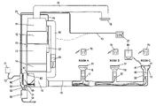
- FIG. 1 shows a conventional residential forced-air HVAC system.
- FIG. 2 shows the zone climate control system as retrofitted into the HVAC system.
- FIGS. 3A and 3B show one method for heating, by which the HVAC controller may determine which vents to open, whether a heating cycle may be performed, and for how long.
- FIG. 4 shows one method of circulation for heating, used for warming up some rooms without running the heater.
- FIGS. 5A and 5B show one method of circulation for temperature equalization, used for correcting over-conditioning of some rooms.
- FIG. 6 shows one method of circulation for maintaining air quality.
- zone climate control system thermal model, and operating methodology will be described with reference to specific embodiments and, in the interest of conciseness, will focus more on heating than on cooling.
- the invention is, of course, not limited to these specific details, which are provided for the reader's convenience and education only.
- FIG. 1 is a block diagram of a typical forced air system.
- the existing central HVAC unit 10 is typically comprised of a return air plenum 11 , a blower 12 , a furnace 13 , an optional heat exchanger for air conditioning 14 , and a conditioned air plenum 15 .
- the configuration shown is called “down flow” because the air flows down.
- Other possible configurations include “up flow” and “horizontal flow”.
- a network of air duct trunks 16 and air duct branches 17 connect from the conditioned air plenum 15 to each air vent 18 in room A, room B, and room C. Each air vent is covered by an air grill 31 .
- the invention is designed for larger houses with many rooms and, typically, at least one air vent in each room.
- the conditioned air forced into each room is typically returned to the central HVAC unit 10 through one or more common return air vents 19 located in central areas. Air flows through the air return duct 20 into the return plenum 11 .
- a thermostat 21 is connected by a multi-conductor cable 73 to an HVAC controller 22 that switches power to the blower, furnace and air conditioner.
- the thermostat commands the blower and furnace or blower and air conditioner to provide conditioned air to cause the temperature at the thermostat to move toward the temperature set at the thermostat.
- FIG. 1 is only representative of many possible configurations of forced air HVAC systems found in existing houses.
- the air conditioner can be replaced by a heat pump that can provide both heating and cooling, eliminating the furnace.
- a heat pump is used in combination with a furnace.
- the present invention can accommodate the different configurations found in most existing houses.
- FIG. 2 is a block diagram of one embodiment of the present invention installed in an existing forced air HVAC system, such as that shown in FIG. 1 .
- the airflow through each vent is controlled by a substantially airtight bladder 30 mounted behind the air grill 31 covering the air vent 18 .
- the bladder is, ideally, either fully inflated or fully deflated while the blower 12 is forcing air through the air duct 17 .
- a small air tube 32 ( ⁇ 0.25′′ OD) is pulled through the existing air ducts to connect each bladder to one air valve of a plurality of servo controlled air valves 40 .
- the air valves are mounted on the side of the conditioned air plenum 15 .
- a small air pump in air pump enclosure 50 provides a source of low-pressure ( ⁇ 1 psi) compressed air and vacuum at a rate of e.g. ⁇ 1.5 cubic feet per minute.
- the pressure air tube 51 connects the pressurized air to the air valves 40 .
- the vacuum air tube 52 connects the vacuum to the air valves.
- the air pump enclosure also contains a low voltage (typically 5 or 12 volts) power supply and control circuit for the air pump.
- the AC power cord 54 connects the system to 110V AC power.
- the power and control cable 55 connect the low voltage power supply to the control processor and servo controlled air valves and connect the control processor 60 to the circuit that controls the air pump.
- the control processor controls the air valve servos to set each air valve to one of two positions. The first position connects the compressed air to the air tube so that the bladder inflates. The second position connects the vacuum to the air tube so that the bladder deflates.
- thermometer 70 is placed in each room in the house. All thermometers transmit, on a shared radio frequency of 418 MHz, packets of digital information that encode 32-bit digital messages.
- a digital message includes a unique thermometer identification number, the temperature, and command data. Two or more thermometers can transmit at the same time, causing errors in the data. To detect errors, the 32-bit digital message is encoded twice in the packet.
- the radio receiver 71 decodes the messages from all the thermometers, discards packets that have errors, and generates messages that are communicated by serial data link 72 to the control processor. The radio receiver can be located away from the shielding effects of the HVAC equipment if necessary, to ensure reception from all thermometers.
- the control processor is connected to the existing HVAC controller 22 by the existing HVAC controller connection 74 .
- the existing thermostat 21 is replaced by a graphical display 80 with a touch sensitive screen.
- the graphical display is connected to the processor using the same wires that had been used by the existing thermostat. Therefore, no new wires need be installed through the walls.
- the program executing in the processor controls the graphical display and touch screen to provide the occupant a convenient way to program the temperature schedules for the rooms and to display useful information about energy usage and the operation of the HVAC system.
- the control processor controls the HVAC equipment and the airflow to each room according to the temperature reported for each room and according to an independent temperature schedule for each room.
- the temperature schedules specify a heat-when-below-temperature and a cool-when-above-temperature for each minute of a 24-hour day. A different temperature schedule can be specified for each day for each room.
- the present invention can set the bladders so that all of the airflow goes to a single air vent, thereby conditioning the air in a single room. This could cause excessive air velocity and noise at the air vent and possibly damage the HVAC equipment.
- This is solved by connecting a bypass air duct 90 between the conditioned air plenum 15 and the return air plenum 11 .
- a bladder 91 is installed in the bypass 90 and its air tube is connected to an air valve 40 so that the control processor can enable or disable the bypass.
- the bypass provides a path for the excess airflow and storage for conditioned air.
- the control processor is interfaced to a temperature sensor 61 located inside the conditioned air plenum.
- the control processor monitors the conditioned air temperature to ensure that the temperature in the plenum does not go above a preset temperature when heating or below a preset temperature when cooling, and ensures that the blower continues to run until all of the heating or cooling has been transferred to the rooms. This is important when bypass is used and only a portion of the heating or cooling capacity is needed, so the furnace or air conditioner is turned only for a short time. Some existing HVAC equipment has two or more heating or cooling speeds or capacities. When present, the control processor controls the speed control and selects the speed based on the number of air vents open. This capability can eliminate the need for the bypass.
- a pressure sensor 62 is mounted inside the conditioned air plenum and interfaced to the control processor.
- the plenum pressure as a function of different bladder settings is used to deduce the airflow capacity of each air vent in the system and to predict the plenum pressure for any combination of air valve settings.
- the airflow to each room and the time spent heating or cooling each room is use to provide a relative measure of the energy used to condition each room. This information is reported to the house occupants via the graphical display screen.
- the present invention uses one instance of a first set of parameters to describe and control the climate control of each respective room, and to make energy usage calculations regarding that room.
- a “room” is defined as a portion of a house associated with a particular smart controller (wireless thermometer 70). In one embodiment, there may be up to 32 rooms.
- the invention also uses one instance of a second set of parameters to describe and control the operation of each HVAC system in the house. In one embodiment, there may be up to 5 HVAC systems.
- the invention also uses a third set of parameters to describe and control the entire house. Customarily, any given room gets its conditioned air supply from a single, predetermined one of the HVAC systems. In other words, the room's ductwork is connected to exactly one HVAC system. This is not a necessary limitation on the invention, although for convenience the house will be described in such terms herein.
- the parameters are either measured, or derived from data measured while controlling the HVAC systems, and they become more accurate over time, as more data are gathered and factored into the derivation.
- default values may be utilized. In some embodiments, the default values may be customized to suit the particular house and/or local climate.
- the current temperature in the room has the most significant impact on whether the HVAC system will be run. If the temperature does not need to be changed in order to bring the room into a specified target temperature range, then the room will not be the cause of the HVAC system being turned on.
- Plenum pressure is predicted according to the equation:
- the plenum pressure should be limited to ⁇ 0.5′′ to 1.0′′ H 2 O (inches of water), equivalent to ⁇ 0.018 to 0.36 psi (pounds per square inch).
- the measured plenum pressure is scaled in a corresponding way, so that when the plenum pressure is 0.5′′ H 2 O, the measured value used in calculations is 500.
- the parameter Airflow X for each room and for the bypass is determined using a set of measured plenum pressures for a set of predetermined combinations of room and bypass vent settings.
- the process for determining Airflow bypass for the bypass is the same as for rooms, so in the following description, the bypass is treated as an additional room.
- the combinations are generated by representing the OPEN/CLOSED states of the vent(s) in rooms as bits in a circular binary array. Suppose there are n ⁇ 1 rooms and a bypass.
- the binary array then has n elements and the elements are numbered 1, 2, . . . , n.
- the array is indexed using modulo arithmetic, so that an index value of n+1 accesses element 1 , n+2 accesses element 2 , etc.
- indexing is “circular” so that the end connects to the beginning.
- the air vent of the corresponding room is CLOSED (room is CLOSED).
- the air vent of the corresponding room is OPEN (room is OPEN).
- the B group starts with n-j rooms OPEN and j rooms CLOSED.
- the first combination in the A group sets rooms 1 through j OPEN and rooms j+1 through n CLOSED, and the plenum pressure PP A1:J is measured.
- the second combination in the A group additionally sets room j+1 OPEN, and the plenum pressure PP A1:j+1 is measured.
- the third combination sets room 1 CLOSED, and the plenum pressure PP A2:j+1 is measured, the fourth combination sets room j+2 OPEN and the plenum pressure PP A2:j+2 is measured.
- Airflow i ( k HAVC /PP Ak:i ) ⁇ ( k HAVC /PP Ak:i ⁇ 1 ) Since k HAVC is a common scale factor, it can be conveniently selected so that the average Airflow i term is about 100 and so that integer arithmetic can be used for the calculations. A value of 200,000 for Airflow i can be used (as described above), so the equation produces a calibrated value for Airflow i . Three other pairs of plenum pressure measurements can be used to find independent measurements of Airflow i : PP Ai:k With PP Ai+1:k PP Bi:k with PP Bi+1:k PP Bk:i ⁇ 1 with PP Bk:i .
- Each pair yields a value of Airflow i for a different set of rooms in combination with the i th room.
- the airflow may be slightly different for different combinations because rooms may share the same trunk duct so that the room airflows are somewhat dependent on each other. Using the average of the four values partially compensated for such dependencies.
- PE i Airflow i ( Airflow i + Airflow j + ... + Airflow n ) where:
- Capacity COOL The cool capacity, Capacity COOL , is the time in seconds the air conditioning must run to lower the temperature of the room by 1 degree, and is similar in nature to Capacity HEAT .
- the heat offset, TempOffset HEAT is an empirical correction factor derived from stored operating data that corrects for secondary heat sources such as sunlight through a window, incandescent lights, appliances, and thermal coupling to other heated rooms. Its units are seconds per hour.
- the calculated LOSS HEAT value is valid only if it has a positive value. If it is zero or negative, the outside temperature is not low enough for the room to need heat.
- the cool offset factor, TempOffset COOL is an empirical factor similar to TempOffset HEAT , and corrects for sources of heating and cooling.
- a source of cooling could be a basement room kept cool by the ground and having little thermal contact with the outside air.
- the calculated LOSS COOL value is valid only if it has a positive value. If it is zero or negative, the outside temperature is not high enough for the room to need cooling.
- Typical rooms have sources of heating, so LOSS HEAT becomes positive only if the outside temperature is several degrees cooler than the target temperature (“heat when below” temperature) for heating. Likewise, LOSS COOL becomes positive when the outside temperature is several degrees cooler than the target temperature for cooling (“cool when above” temperature).
- the fan speed is lowest for the circulation function, higher for the heating function, and highest for the cooling function. Since the plenum pressure increases as fan speed increases, the plenum pressure K HVAC scale factors K HEAT , K COOL , and K CIR , are different for the functions as described above. The calibration process is done using the circulation function, so K CIR is arbitrarily set to a value of 200,000. K HEAT and K COOL are then determined by comparing the measured plenum pressure for the heating and cooling functions with the predicted plenum pressure using K CIR .
- the thermal behavior of the house as a whole is the composite of the behaviors of all of the rooms. Therefore there is a set of six corresponding thermal parameters for the whole house: Capacity HEAT , TempOffset HEAT , UF HEAT , Capacity COOL , TempOffset COOL , and UF COOL , which are used to calculate LOSS HEAT and LOSS COOL , and to control the HVAC equipment to achieve the desired temperatures in each of the rooms. There is no separate Airflow factor for the whole house.
- the room When the outside temperature is cold enough to require heating of a room, the room is heated (by warm air flow) for a period of time and its temperature increases. The room is then unheated for a period of time while the Capacity HEAT of the room supplies the heat lost to the outside (and perhaps to other rooms) and its temperature decreases. After some period of time, the temperature will have decreased sufficiently such that heating is again required for the room.
- the time between the heating cycles, and the difference between the outside temperature and the room temperature can be used to calculate the heat lost (LOSS HEAT ) during that period.
- the Capacity HEAT is then (heat lost)/(room temperature change). This is more accurate if the average of the LOSS HEAT at the beginning of the period and the LOSS HEAT at the end of the period is used. Using the average is important when the outside temperature changes significantly during the measurement period.
- parameters are measured and stored for each room as the system controls the heating cycles according to the temperatures in the rooms.
- a Capacity HEAT is calculated for each room and for each time period between the heating cycles for that room. (Since rooms are heated only when needed, the time period between cycles is typically different for different rooms.)
- the individual measurements of Capacity HEAT are accumulated, and at the end of the 24-hour period, the average Capacity HEAT is calculated for each room and is stored into long term storage.
- Capacity HEAT is meaningful only if the room continuously cools between heating cycles, the change in temperature between cycles is sufficient to be measured accurately, and the environment (outside air temperature and activity in the room) has not changed significantly between heating cycles.
- the temperature measurement has a resolution of 0.25 degree, so the change in temperature needs to be at least 0.5 degree for the measurement to have any significance.
- a special case occurs when the target heat temperature is reduced. The time between heating cycles may be unusually long since the room temperature may decrease several degrees before heating is required, so it is likely the environment will change significantly before heating in again needed. However, the larger change in room temperature will produce a more accurate measurement of Capacity HEAT .
- Capacity HEAT is calculated.
- the measured value of Capacity HEAT is used in the average only if all of the following conditions are satisfied:
- Capacity COOL is similar. When the outside temperature is high enough to require the room to be cooled, the room temperature decreases while the room receives cool airflow. The temperature increases between cooling cycles as heat from the outside overcomes the Capacity COOL of the room at a rate of LOSS COOL . Capacity COOL is then (heat gain)/(room temperature change).
- Capacity COOL or Capacity HEAT may be measured. If both heating and cooling are used during the 24-hour period, the environmental conditions are extremely variable and the Capacity values measured are likely to have large errors. Therefore no value for either Capacity is stored long term.
- the system gathers the following data and stores it for a relatively short period of time, such as a few days.
- the total storage for one day is set to 32 Kbytes so that one bank of flash memory can store two days of data for a maximally configured system with 32 rooms and 5 HVAC systems.
- the system includes flash memories, operated in ping-pong fashion in which one memory or block is used until it is full, and then the other, older block is erased and used for new data.
- This structure requires 4 bytes of storage per transition.
- the total daily short term data storage provided is:
- 13 segments of 64 Kbytes (851,968 bytes) are allocated for long term storage, enough for 508 days.
- TempOffset HEAT ( 1 N ) * ( sum ⁇ ( Loss HEAT ) - sum ⁇ ( temp room - temp outside ) )
- LOSS HEAT is the stored prorated heating time (appropriately scaled to account for conversion from seconds to hours).
- the method for calculating TempOffset COOL and UF COOL is identical, except the prorated time for cooling is used to determine LOSS COOL .
- the thermal mode parameters are calculated for each room based on the short term data gathered for that day.
- Each cycle of HVAC activity for a room is evaluated as a pair of data values where one value is the Loss (3,600*[prorated seconds of*HVAC activity]/[time between cycles]), and the other value is the difference between the room temperature at the beginning of the cycle and the outside temperature.
- the Airflows value for each room is determined through the set of measurements and calculations described above in section II.A.1.b.
- Default values are automatically assigned to the other six parameters: Capacity HEAT , UF HEAT , TempOffset HEAT , Capacity COOL , UF COOL , and TempOffset COOL .
- the quality of the default values is important, to make the system work as well as possible upon initial installation, to avoid customer dissatisfaction during the first few days while the system extracts calibrated values from measured data.
- the default values should, ideally, be customized for the local climate at that particular time of year, and for the house itself e.g. the size of the house and the quality of its insulation. These default values will typically assume that the HVAC system is properly designed.
- a properly designed heating system can keep the house at 70 degrees on the coldest day, and a properly designed cooling system can keep the house at 72 degrees on the hottest day.
- a properly designed HVAC system can heat or cool the house temperature 5 degrees per hour.
- a properly designed heat pump system can typically change the house temperature only 2 degrees per hour, however.
- the airflow to each room should be proportional to the heating and/or cooling requirements of that room; however, in practice, most houses have problems here, and sometimes they are significant problems.
- UF HEAT ( 60 ⁇ ⁇ sec min * 60 ⁇ ⁇ min hour * Airflow i ) ( TargetTemp HEAT - climate MIN - TempOffset HEAT )
- UF COOL ( 60 ⁇ ⁇ sec min * 60 ⁇ ⁇ min hour * Airflow i ) ( climate MAX + TempOffset COOL - TargetTemp COOL )
- Capacity HEAT 60 ⁇ ⁇ sec min * 60 ⁇ ⁇ min hour 2 ⁇ ⁇ ⁇ degrees * Airflow i
- Capacity COOL 60 ⁇ ⁇ sec min * 60 ⁇ ⁇ min hour 2 ⁇ ⁇ ⁇ degrees * Airflow i
- the “5 degrees” factor is default degrees per hour the heating or cooling system can change the temperature of the whole house. This should be “2 degrees” for heat pumps.
- the temperature control method uses the thermal model, described above, to predict the conditioning time (in seconds) needed to keep all of the rooms within a predetermined number of degrees—DeltaT—of the target temperature.
- a reasonable default value for this global parameter may be 1 degree, but it may be changed, based on field experience, the local climate, and the homeowner's preference.
- Heating it is acceptable to heat a room until its temperature is DeltaT above its target heating temperature.
- cooling it is acceptable to cool a room until its temperature is DeltaT below its target cooling temperature.
- the temperature control method attempts to make each cycle at least a minimum duration, if possible.
- a reasonable minimum duration may be 15 minutes.
- bypass it may be necessary to use a lower duration target, to avoid overheating or overcooling the plenum; therefore, the method attempts to maximize the number of open vents, and will reduce the cycle time, to avoid using the bypass, if possible.
- the amount of heating and cooling needed for each room during the next 15 minutes is calculated, in seconds.
- the target temperature used for this calculation is adjusted by DeltaT. If the time value is negative, it is set to zero. In order to ensure that both heating and cooling are never required at the same time, the system may require that the TargetTemp HEAT be at least twice DeltaT below the TargetTemp COOL .
- TargetTemp HEAT and TargetTemp COOL are specified with 1-degree resolution, while the wireless thermometers report the current temperature with 0.25-degree resolution.
- FIGS. 3A and 3B illustrate one exemplary embodiment of a method 100 of operating an HVAC system to heat rooms of a house.
- a similar method may be used for cooling, but for simplicity, only a heating method will be described.
- the room's vents are either OPEN or CLOSED, controlling whether heated air is, or is not, supplied to the room.
- the HVAC controller may begin by logically setting ( 103 ) all room vents to CLOSED. Then, the vents are set ( 104 ) to OPEN for all rooms which need heat.
- the HVAC controller calculates ( 105 ) the time HEAT (total time), in seconds, of heating required to raise all OPEN rooms to their respective TargetTemp HEAT settings+DeltaT.
- the time HEAT-ROOM for each room is: Capacity HEAT *(TargetTemp HEAT +DeltaT ⁇ room temperature)+LOSS HEAT where LOSS HEAT is calculated from the equation for the room, using the current room temperature, outside temperature, and an initial time of 15 minutes (the target time between HVAC cycles).
- This total heating required is time HEAT , the sum of the time HEAT-ROOM values for each of the rooms that need heat.
- the time HEAT-ROOM is calculated again for each room with its vent OPEN (called an OPEN room) using the prorated ( 106 ) heat to the room using the Airflow parameters of all OPEN rooms and using time HEAT as the time between HVAC cycles. This compensates for the potential unequal distribution of the airflow to the OPEN rooms.
- the shortest of these time HEAT-ROOM values is the time HEAT that will not overheat any of the OPEN rooms. (A room is considered overheated if it is more than DeltaT warmer than its TargetTemp HEAT .)
- the HVAC controller then calculates ( 107 ) the longest duration time HEAT for which the heater may be run, without overheating any OPEN room.
- the HVAC controller calculates ( 109 ) the predicted plenum pressure PP pred according to the Airflow values of the OPEN vents. If ( 110 ) the predicted plenum pressure is less than or equal to the specified maximum plenum pressure PP max , the heater is run ( 111 ) for the time HEAT duration.
- the HVAC controller attempts to lower the plenum pressure by various means.
- the HVAC controller first attempts to lower the plenum pressure by sequentially opening additional room vents at the cost of reducing the time HEAT .
- the HVAC controller logically sets ( 113 ) the vent to OPEN and time HEAT is calculated again.
- the calculated time HEAT for each candidate room is compared ( 114 ), and if the longest time HEAT is greater than a predetermined threshold, such as 120 seconds, the HVAC controller sets the vent for that one room OPEN and goes back (A) to again predict ( 109 ) the plenum pressure.
- a predetermined threshold such as 120 seconds
- the HVAC controller sets ( 115 ) the bypass to OPEN. All of the rooms previously set open (in 113 ) are set CLOSED, since they do not require heat this cycle, but were set OPEN only as a means of reducing plenum pressure.
- the HVAC controller then again predicts ( 116 ) the plenum pressure with the bypass set OPEN. If ( 117 ) the plenum pressure is less than or equal to the maximum, the heater is run ( 118 ) for the time HEAT duration calculated for the rooms set OPEN. Otherwise, the HVAC controller may take further measures to try to lower the plenum pressure.
- the HVAC controller sets ( 119 ) OPEN the CLOSED room that will reduce time HEAT the least if heated to DeltaT plus its TargetTemp HEAT . If ( 121 ) the time HEAT is greater than a second threshold, e.g. 60 seconds, the HVAC controller then again predicts ( 116 ) the plenum pressure. Otherwise, the HVAC controller predicts ( 122 ) the plenum pressure and, if ( 123 ) the predicted plenum pressure is below the maximum allowed, the heater is run ( 124 ) for the second threshold of time. Otherwise, the HVAC controller ( 125 ) searches one at a time for the room currently CLOSED that would be least above its TargetTemp HEAT if heated for 60 seconds. That room is set OPEN and the HVAC controller returns to ( 122 ) to predict the plenum pressure. This is repeated until sufficient rooms are set OPEN so that with bypass set OPEN, the plenum pressure is less than the maximum.
- a second threshold e.g. 60 seconds
- the heating control process is to always provide heat to all rooms below their TargetTemp HEAT .
- the time HEAT is maximized by also heating rooms up to DeltaT above their TargetTemp HEAT . If the plenum pressure is too high with just these rooms set OPEN, rooms are set open one at a time, selected in the order that reduces time HEAT the least. Rooms are added until the plenum pressure is satisfied or until the time HEAT becomes less than 120 seconds. If the time HEAT becomes less than 120 seconds, all the rooms set OPEN that reduced the time HEAT are set CLOSED and the bypass is set OPEN. If the plenum pressure is not satisfied, rooms are again added one at a time selected in the order that reduces time HEAT the least.
- time HEAT becomes less than 60 seconds it is set to 60 seconds and the CLOSED rooms are search one at a time for the one room that will be the closest to its TargetTemp HEAT if heated for 60 seconds, and that room is set OPEN. Rooms are added one at a time until the plenum pressure is satisfied. Then the rooms now set OPEN are heated for 60 seconds.
- the method for cooling is similar to the method for heating, appropriately exchanging the roles of TargetTemp COOL and TargetTemp HEAT , and using the corresponding values and equations for LOSS COOL and Capacity COOL . It is much less likely that rooms will be overcooled than overheated, because there are many sources of heating and only few sources of cooling.
- circulation may be used to heat, cool, equalize temperatures, or maintain air quality.
- Four different conditions are considered for circulation:
- each temperature schedule setting for each room specifies a low, medium, or high level of circulation, which influences how circulation is used.
- circulation is only used to ensure a minimum of new air is sent to the room each day, or as a last resort source of heat or cool to satisfy another room which has a high circulation setting.
- the low circulation setting is ordinarily only applied to rooms that are set for minimal conditioning to save energy.
- the room can be used as a source of heat or cool, but does not itself trigger circulation for equalization if its temperature is significantly greater than its TargetTemp HEAT or significantly less than its TargetTemp COOL ; in other words, a medium circulation room accepts over-conditioning.
- the room calls for circulation when it is excessively conditioned.
- a room is considered excessively conditioned (different than over-conditioned) when it is more than a predetermined threshold, such as 3 degrees above its TargetTemp HEAT or below its TargetTemp COOL .
- a predetermined threshold such as 3 degrees above its TargetTemp HEAT or below its TargetTemp COOL .
- the excessively conditioned thresholds may have seasonal adjustments; for example, a room may be excessively heated if it is 3 degrees too hot in the summer, but 5 degrees too hot in the winter.
- Circulation for temperature equalization or control is only utilized when the temperature difference between the warmest and coolest participating rooms is greater than a predetermined threshold, such as 3 degrees.
- the bypass is not used in circulation for temperature equalization; sufficient vents are opened to prevent over-pressurizing the plenum and to maximize the effect of circulation.
- Circulation for air quality is done when most cost effective. During heating season, circulation to unconditioned rooms is done in the afternoon, when the outside temperature is highest. During cooling season, circulation to unconditioned rooms is done after midnight, when the outside temperature is lowest.
- FIG. 4 illustrates one embodiment of a method 140 of circulation for heating, such as may be employed when a normal heating cycle is not needed because no room is yet below its TargetTemp HEAT .
- the HVAC controller starts by finding ( 141 ) the lowest temperature room which can use heat (meaning it is less than DeltaT above its TargetTemp HEAT ) and which has a medium or high circulation setting. Low circulation rooms are not considered because they are minimally conditioned, and not heated until below their TargetTemp HEAT .
- the HVAC controller finds ( 144 ) the highest temperature room that does not need heat (is more than DeltaT above its TargetTemp HEAT and thus can be a source of heat. This room is potentially the heat source room for heating the cold room by circulation.
- the HVAC controller logically sets ( 147 ) all rooms vents to CLOSED, sets ( 148 ) the vents of the heat source room and the room to be heated OPEN, and sets ( 149 ) to OPEN the vents of all rooms which can use heat and whose temperature is at least the threshold amount, such as 3 degrees, cooler than the heat source room.
- the HVAC controller attempts to increase the amount of heat source, by setting ( 150 ) to OPEN all rooms which (1) do not need heat and (2) are at least the threshold amount warmer than the coolest OPEN room which can use heat.
- the HVAC controller then predicts ( 151 ) the plenum pressure. If ( 152 ) the predicted plenum pressure is less than or equal to the maximum allowed, the HVAC controller causes the HVAC system to circulate ( 153 ) the air into the participating rooms for a predetermined amount of time, such as 10 minutes. In some embodiments, the amount of time may be determined according to dynamic factors, such as the total Capacity HEAT of the participating rooms.
- the HVAC controller attempts to lower the pressure by finding ( 154 ) the warmest CLOSED room not needing heat. If ( 155 ) the temperature in that room is greater than the temperature in the warmest room that can use heat, then that room can be used as a heat source, although it may not be an especially good one, such as if its temperature is only very slightly above that in the warmest room that can use heat.
- the HVAC controller sets ( 157 ) that room's vent OPEN, and goes back to re-predict ( 151 ) the plenum pressure and so forth.
- the method for circulation cooling is substantially similar to the method for circulation heating.
- Circulation for equalization is used to reduce excessive conditioning and to keep temperatures more equalized. It is done only for rooms having the high circulation setting.
- FIGS. 5A and 5B illustrate one embodiment of a method ( 170 ) of performing circulation for reducing excessive conditioning and equalizing room temperatures.
- the method is explained in terms of the heating function, but the same or a similar method can be employed to reduce excessive cooling, as well. Excessive cooling is less likely than excessive heating, because the house has numerous sources of supplemental heat, such as incandescent lights, appliances, an oven, a cooktop, sunlight, people, and so forth, and there are few sources of supplemental cool.
- the HVAC controller starts by logically initializing all vents to CLOSED state. It then searches to find ( 171 ) the warmest room which is at least 3 degrees excessively heated and has a high circulation setting. If ( 172 ) no such room is found, circulation for equalization is not needed. Otherwise, a “hot room” has been found, which needs to be cooled down toward its TargetTemp HEAT . The hot room temperature will be lowered by mixing hot air from the hot room with air from a cooler room, the “source of cool”.
- the HVAC controller tries to find ( 174 ) the coolest room which is at least 3 degrees cooler than the hot room, and which has a circulation setting of high or medium. If ( 175 ) no such room is found, the HVAC controller tries to find ( 176 ) the next preferred type of source of cool, the coolest room that has a low circulation setting and that has not had sufficient circulation yet today to maintain its air quality. If ( 177 ) no such room is found, the HVAC controller tries ( 178 ) to find the next preferred type of source of cool, the coolest room that has a low circulation setting and that has received sufficient circulation already today. If ( 179 ) no such room is found, there simply is not a suitable source of cool, and circulation for equalization cannot be performed ( 180 ).
- the HVAC controller logically sets ( 181 ) the vents in that room and in the hot room OPEN. To maximize the redistribution of heat, the HVAC controller also sets ( 182 ) OPEN the vents of all rooms that are at least 3 degrees excessively heated, have the high circulation setting, and are warmer than the cool room. To maximize the effectiveness of the cooling, the HVAC controller also sets ( 183 ) OPEN the vents of all rooms that: (1) are at least 3 degrees cooler than the warmest excessively heated room, and (2) have (a) high or medium circulation settings, or (b) the low circulation setting and have not received sufficient circulation yet today.
- the HVAC controller predicts ( 189 ) the plenum pressure. If ( 190 ) the predicted plenum pressure is less than or equal to the maximum allowable pressure, the fan is run ( 191 ) for a predetermined period of circulation, such as ten minutes. As air is pushed into the overheated rooms and the source of cool rooms, it will mix in the hallways etc. and in the plenum, quickly equalizing to a middle temperature cooler than the overheated rooms were and warmer than the source of cool rooms were.
- the HVAC controller attempts to lower it by opening more vents.
- the HVAC controller attempts to find ( 192 ) the coolest CLOSED room that has the medium or high circulation setting. If ( 193 ) the temperature in that room is lower than that of the coolest overheated room, the HVAC controller sets ( 194 ) that room's vents OPEN, and goes back to re-predict ( 189 ) the plenum pressure. Otherwise, the HVAC controller attempts to find ( 195 ) the coolest CLOSED room with the low circulation setting and insufficient air circulation today, which is at least 3 degrees cooler than the warmest excessively heated room.
- the HVAC controller sets ( 197 ) its vents OPEN, and goes back to re-predict ( 189 ) the plenum pressure. Otherwise, the HVAC controller attempts to find ( 198 ) the coolest CLOSED room with the low circulation setting and sufficient circulation, which is cooler than the warmest excessively heated OPEN room. If ( 199 ) such a room is found, the HVAC controller sets ( 200 ) its vents OPEN, and goes back to re-predict ( 189 ) the plenum pressure. Otherwise, there are no suitable rooms whose vents can be opened to lower the plenum pressure, and circulation for equalization cannot be performed ( 201 ).
- FIG. 6 illustrates one embodiment of a method ( 210 ) for circulating the air to maintain air quality, particularly in rooms which are set to minimal conditioning for energy savings, and therefore not conditioned each day.
- the HVAC controller starts by logically setting ( 211 ) all vents CLOSED. For each room, the HVAC controller goes back through its stored data for the previous period of time, such as 24 hours, and adds ( 212 ) up the total time the room received airflow. If ( 213 ) the total time for every room is above some threshold, such as some predetermined minimum, there is no need ( 214 ) for circulation, as every room has already received sufficient circulation today and will have adequate air quality.
- some threshold such as some predetermined minimum
- the HVAC controller sets ( 215 ) OPEN the vents of all rooms which have not had sufficient circulation.
- the HVAC controller predicts ( 216 ) the plenum pressure. If ( 217 ) the predicted plenum pressure is less than or equal to the maximum allowed, the HVAC controller turns on the fan to circulate ( 218 ) the air for a predetermined period of time, such as 10 minutes. In some embodiments, the period of time may be dynamically determined, such as in response to the least amount of prior circulation, or the Airflow parameters of the OPEN rooms.
- the HVAC controller sets ( 219 ) the bypass OPEN, and re-predicts ( 220 ) the plenum pressure. If ( 221 ) the plenum pressure is low enough, the HVAC controller runs the fan to circulate ( 222 ) the air for a predetermined period, such as 10 minutes. Otherwise, the HVAC controller attempts to lower the plenum pressure by opening the vents of certain rooms which do not actually need circulation.
- the HVAC controller finds ( 223 ) the CLOSED room whose temperature is closest to the average temperature of the OPEN rooms.
- the HVAC controller sets ( 226 ) its vents OPEN, and goes back to re-predict ( 220 ) the plenum pressure.
- the bypass is used in preference to using more rooms, to reduce the mixing of conditioned and unconditioned air.
- the seven room parameters, and other data, are also used for providing an accurate “anticipation” function when one or more different temperature schedules (“setback”) are in use.
- Anticipation is needed when making a transition to a new target temperature that requires an increase in energy usage—moving to a higher TargetTemp HEAT or a colder TargetTemp COOL , because the user commonly understands the schedule time to specify the time at which the room should be at the new target temperature, not the time at which the HVAC system should begin heating or cooling to the new target temperature. It takes some amount of time for the HVAC system to raise or lower the house temperature, so heating or cooling must be started early, to reach the new target temperature by the specified time.
- the amount of anticipation time needed such as the outside temperature, the Capacity of the rooms, the number of rooms moving to a new target temperature, the Airflow available to those rooms, and so forth.
- the anticipation function uses the thermal model described above, and looks ahead in time for the changes in target temperature that will require additional conditioning. The time when the new target temperature becomes effective is advanced sufficiently to ensure that the new target temperature is reached at or before its specified time.
- the anticipation function calculates an anticipation time for every room, responding to changes in room temperature and outside temperature.
- the anticipation function is a separate process from the HVAC temperature control process described above. The temperature control process adds the separately calculated anticipation time to the current time, and uses this adjusted time to get the target temperatures from the programmed temperature schedules. This is a simple way to cleanly separate the longer-term anticipation function from the shorter-term HVAC control function.
- the anticipation function considers the capacity of the HVAC system, and the ability to use that capacity to change the temperature in each room. Even though the HVAC equipment may have sufficient capacity, it may not be possible to effectively get the capacity to the room needing the temperature change.
- a portion of the total HVAC conditioning capacity is needed for keeping the rooms at their current temperatures. This is calculated by summing the LOSS HEAT or LOSS COOL for all the rooms. The excess heating capacity available to raise the temperature can be calculated as
- the excess cooling capacity is calculated similarly. As the outside temperature becomes more extreme, there is less excess capacity available for changing the room temperature.
- the maximum conditioning that can be delivered to a room is proportional to the room's Airflow.
- the fraction Frac i of the excess conditioning that can be delivered to a room is roughly
- Frac i Airflow i * PP max k HVAC
- Frac i Airflow i sum ⁇ ( Airflow i )
- the sum is taken over all the rooms that are changing target temperatures in a way that requires more conditioning at the same time. This calculation takes into account the time calculated the last time the anticipation function was executed.
- Airflow i sum ⁇ ( Airflow i ) ⁇ Airflow i * PP max k HVAC ⁇ ⁇ then Frac i Airflow i sum ⁇ ( Airflow i ) is used, and the anticipation is recalculated. This makes the anticipation longer, so the overlap of anticipation must be checked again, and Frac i adjusted if necessary. This iteration continues until Frac i is acceptably stable for this room, such as the value changes less than 5% between iterations.
- the HVAC controller must limit the amount of anticipation time to some predetermined maximum, such as 4 hours.
- Anticipation is regularly calculated as part of the main control loop. Anticipation has no effect when the change in target temperature is farther in the future than the anticipation value.
- the anticipation value strongly depends on the outside temperature, and changes as the outside temperature changes. Therefore, the anticipation value needs to be recalculated fairly frequently. For example, if the outside temperature at 4 am is 20 degrees, and there is a 5 degree increase in room temperature scheduled for 10 am, the anticipation value calculated at 4am might be 3 hours, suggesting that the heating will need to be turned on at 7 am. However, when 7 am arrives, the outside temperature may have risen to 40 degrees, resulting in an anticipation value of only 2 hours, or 8 am. In this instance, the rising outside temperature shortens the anticipation value, causing the turn-on time to recede into the future. The opposite can also happen, when a falling outside temperature causes the anticipation value to increase and the turn-on time to advance earlier and earlier.
- the same general methodology can be used with cooling, but with the opposite effects caused by changing outside temperatures, of course.
Abstract
Description
-
- A. Forced Air Central HVAC Systems
- B. Retrofit Zone Climate Control System
-
- A. Parameters
- 1. Room Parameters
- 2. HVAC System Parameters
- 3. House Parameters
- 4. Delta Values
- B. Stored Data
- 1. Short Term Data Storage
- a. Room Short Term Data
- b. HVAC System Short Term Data
- c. House Short Term Data
- 2. Long Term Data Storage
- a. Room Long Term Data
- b. HVAC System Long Term Data
- c. House Long Term Data
- 1. Short Term Data Storage
- C. Calibrating the Thermal Model Using the Stored Data
- A. Parameters
-
- A. Initial Installation
- B. Temperature Control
- 1. Heating
- 2. Cooling
- C. Circulation
- 1. Circulation for Heating
- 2. Circulation for Cooling
- 3. Circulation to Reduce Over-Conditioning
- 4. Circulation for Air Quality
- D. Anticipation
where:
-
- PP is the predicted plenum pressure.
- KHVAC is one of a set of calibration or scaling factors determined during installation of the HVAC system which includes the plenum whose pressure is being predicted and which supplies conditioned air to this room. There is a different KHVAC scaling factor for each HVAC function, because the fan is typically set up to run at different speeds for heating, cooling, and circulation. These specific factors are KHEAT, KCOOL, and KCIR, and the appropriate one is used as KHVAC in predicting plenum pressure, according to which type of HVAC function is to be performed. Some HVAC systems have two or more selectable heating or cooling rates. For these systems, a separate KHVAC factor is used for each rate to account for different fan speeds.
- AirflowX is the airflow parameter of each room or bypass which has its vents set open. Airflowbypass is included if the bypass is open, because the bypass contributes to lowering plenum pressure.
| A Group | B Group | ||
| PPA1:2 | 110000 | PPB1:4 | 111100 | ||
| PPA1:3 | 111000 | PPB1:5 | 111110 | ||
| PPA2:3 | 011000 | PPB2:5 | 011110 | ||
| PPA2:4 | 011100 | PPB2:6 | 011111 | ||
| PPA3:4 | 001100 | PPB3:6 | 001111 | ||
| PPA3:5 | 001110 | PPB3:7 | 101111 | ||
| PPA4:5 | 000110 | PPB4:7 | 100111 | ||
| PPA4:6 | 000111 | PPB4:8 | 110111 | ||
| PPA5:6 | 000011 | PPB5:8 | 110011 | ||
| PPA5:7 | 100011 | PPB5:9 | 111011 | ||
| PPA6:7 | 100001 | PPB6:9 | 111001 | ||
| PPA6:8 | 110001 | PPB6:10 | 111101 | ||
PP Ak:i−1 =k HAVC/sum(Airflowk:i−1)
PP Ak:i =k HAVC/(sum(Airflowk:i−1)+Airflowi)
This pair can be combined to eliminate the term: sum(Airflowk:i−1), the combined airflow for the common set of rooms that are OPEN for the two measurements. The resulting equation is:
Airflowi=(k HAVC /PP Ak:i)−(k HAVC /PP Ak:i−1)
Since kHAVC is a common scale factor, it can be conveniently selected so that the average Airflowi term is about 100 and so that integer arithmetic can be used for the calculations. A value of 200,000 for Airflowi can be used (as described above), so the equation produces a calibrated value for Airflowi. Three other pairs of plenum pressure measurements can be used to find independent measurements of Airflowi:
PPAi:k With PPAi+1:k
PPBi:k with PPBi+1:k
PPBk:i−1 with PPBk:i.
Each pair yields a value of Airflowi for a different set of rooms in combination with the ith room. The airflow may be slightly different for different combinations because rooms may share the same trunk duct so that the room airflows are somewhat dependent on each other. Using the average of the four values partially compensated for such dependencies.
where:
-
- PEi is the energy prorated to the roomi; and
- AirflowX is the airflow parameter of each room which has its vent OPEN. The bypass is not included, because it does not materially contribute to energy usage.
LossHEAT=TempOffsetHEAT+(Temproom−Tempoutside)*UFHEAT
where:
-
- LOSSHEAT is the time in seconds the furnace would have to run per hour to supply the heat needed to maintain a constant room temperature. This value assumes that all of the furnace's heat could be sent to this one room; this cannot happen in most systems since the plenum pressure would be too high. Therefore, when the LOSSHEAT factor is actually used, it is scaled by the prorated airflow being provided to the room.
- TempOffsetHEAT is as described above.
- Temproom is the current temperature in the room.
- Tempoutside is the current temperature outside the house.
- UFHEAT is an empirical energy usage factor, derived from operating data. It is related to the reciprocal of the more familiar insulation “R factor”. UFHEAT represents the rate of increase in energy usage needed to keep a room at the target temperature as the outside temperature drops. Its units are seconds per hour per degree.
LossCOOL=TempOffsetCOOL+(Temproom−Tempoutside)*UFCOOL
where:
-
- LOSSCOOL is the time in seconds the air conditioner must run per hour to supply the cooling to maintain a constant room temperature. When it is used, it is scaled by the prorated airflow.
- Temproom is the current temperature of the room.
- Tempoutside is the current outside temperature.
- UFCOOL is an empirical factor, derived from operating data, which represents the rate of energy usage needed to keep the room at the target temperature as the outside temperature increases. Its units are seconds per hour per degree. Its sign is negative, since (Temproom−Tempoutside) becomes more negative as the outside temperature increases.
-
- 1. The change in room temperature is more than 0.5 degree during the measurement period.
- 2. The calculated LOSSHEAT is positive at the beginning and end of the measurement period.
- 3. The measured CapacityHEAT is greater than 10% of the average LOSSHEAT, during the measurement period. If CapacityHEAT is small compared to LossHEAT, It does not contribute significantly to any of the methods used to control the HVAC system. This also helps prevent the average CapacityHEAT for the 24-hour period from being distorted by a temporary source of heat such as a fireplace.
-
- The ID number of the room and the settings for quiet mode (which causes the system to use a reduced plenum pressure when this room is receiving airflow and the relative amount of circulation to use to control the temperature (low, medium, or high), etc., 1 byte.
- New target heat temperature, 1 byte.
- New target cool temperature, 1 byte.
- Transition time since midnight, scaled to 6-minute units to fit in 1 byte and match the sampling rate of the temperatures.
-
- Cycle start time, in seconds since midnight, divided by 2 so it fits in 2 bytes.
- HVAC equipment duration, in seconds, stored in 2 bytes. This is the actual time the heat source or cool source used energy during the cycle.
- Dead time of the cycle, which is the difference in seconds between the total time of the cycle and the HVAC equipment duration, stored in 1 byte. This is the time used to set the airflow control valves (inflate or deflate the bladders) before the start of HVAC equipment duration plus the additional circulation time after the HVAC equipment duration to fully extract the heating or cooling inn the plenum.
- ID number (1-5) of the HVAC system running the cycle, 1 byte.
- HVAC activity type, 1 byte comprising 8 bit fields each indicating whether the HVAC cycle included the bypass, the outside air vent, and any combination of the 6 HVAC controls used turn on the fan, heating, cooling, etc.
- Rooms whose vents were open for the cycle, indicated by 32 respective bit fields in a 4-byte word.
- Minimum plenum pressure measured during the cycle, scaled to fit in a 1-byte value.
- Maximum plenum pressure measured during the cycle, scaled to fit in a 1-byte value.
- Predicted plenum pressure measured during the cycle, scaled to fit in a 1-byte value.
- Minimum plenum temperature measured during the cycle, 1-byte.
- Maximum plenum temperature measured during the cycle, 1-byte.
- Minimum humidity measured during the cycle, 1-byte.
- Maximum humidity measured during the cycle, 1-byte.
-
- Minimum temperature measured in the room, 1 byte
- Maximum temperature measured in the room, 1 byte
- Average temperature measured in the room, 1 byte
- Average difference between the room temperature and the outside temperature (the average of the 240 differences measured during the 24-hour period), 1 byte.
- Maximum negative difference between the measured room temperature and the target heat temperature, 1 byte. In other words, the most “too cold” the room was when it should have been heated.
- Maximum positive difference between the measured room temperature and the target cool temperature, 1 byte. In other words, the most “too hot” the room was when it should have been cooled.
- Prorated number of seconds of HVAC activity for the room, divided by 2 so it fits in 2 bytes, for each of the 6 HVAC controls, for a total of 12 bytes. This data is used to calculate the UF and Offset parameters for the thermal model.
- Minimum humidity measured in the plenum when the room was receiving airflow for the HVAC cycle, 1 byte.
- Maximum humidity measured in the plenum when the room was receiving airflow for the HVAC cycle, 1 byte.
- Average humidity measured in the plenum when the room was receiving airflow for the HVAC cycle, 1 byte.
- Average signal strength of the room's Smart Controller as measured at the central receiver, 1 byte.
- The number of commands received from the room's Smart Controller, 1 byte.
- Room status settings including quiet mode, circulation mode, etc., one byte.
- UFHEAT calculate for the day, 1 byte.
- TempOffsetHEAT/UFHEAT calculated for the day, 1 byte.
- UFCOOL calculate for the day, 1 byte.
- TempOffsetCOOL/UFCOOL calculated for the day, 1 byte.
- CapacityHEAT measurement for the day, 2 bytes.
- CapacityCOOL measurement for the day, 2 bytes.
-
- Data for the cycle which produced the highest plenum pressure, 18 bytes.
- Data for the cycle which produced the largest difference between the predicted plenum pressure and the measured maximum plenum pressure, 18 bytes.
- Data for the cycle which produced the highest plenum temperature, 18 bytes.
- Data for the cycle which produced the lowest plenum temperature, 18 bytes.
- Data for the cycle which produced the highest measured humidity, 18 bytes.
- Data for the cycle which produced the lowest measured humidity, 18 bytes.
- Total number of HVAC cycles, 1 byte.
- Total number of cycles for each of the 6 HVAC controls, 6 bytes total.
- Total time, in seconds/2, that each of the 6 HVAC controls were active, 12 bytes total.
- Number of commands entered at the touch screen controlled by this HVAC system, 2 bytes.
-
- Date (year, month, date), 4 bytes.
- Control mode or program active at the end of the day, 1 byte.
- Minimum outside temperature, 1 byte.
- Maximum outside temperature, 1 byte.
- Average outside temperature, calculated as the average of the 240 stored measurements, 1 byte.
- Minimum inside temperature in any room, 1 byte.
- Maximum inside temperature in any room, 1 byte.
- Weighted average inside temperature in any room, based on weightings which take into account the UFHEAT and UFCOOL for each room, 1 byte.
- Weighted average difference between inside and outside temperature, based on the difference between each room and the outside temperature, weighted by the average of UFHEAT and UFCOOL for each room, 1 byte.
- Weighted average target heat to temperature, 1 byte.
- Weighted average target cool to temperature, 1 byte. The weighted average target temperatures are calculated by averaging the target temperatures for each room over the 24-hour periods, and weighting them according to the UF factors for each room.
LossHEAT=TempOffsetHEAT+(Temproom−Tempoutside)*UFHEAT
y=a+b*x
where sum(xi) is the sum of all the x values for the N measurements.
where LOSSHEAT is the stored prorated heating time (appropriately scaled to account for conversion from seconds to hours).
TempOffsetHEAT=10 degrees
TempOffsetCOOL=10 degrees
CapacityHEAT*(TargetTempHEAT+DeltaT−room temperature)+LOSSHEAT
where LOSSHEAT is calculated from the equation for the room, using the current room temperature, outside temperature, and an initial time of 15 minutes (the target time between HVAC cycles). This total heating required is timeHEAT, the sum of the timeHEAT-ROOM values for each of the rooms that need heat.
-
- 1) Heating is needed in one or more rooms, and one or more rooms can be a source of heat.
- 2) Cooling is needed in one or more rooms, and one or more rooms can be a source of cool (sink of heat).
- 3) No room needs heating or cooling, but one or more rooms are over-conditioned (significantly above their TargetTempHEAT or significantly below their TargetTempCOOL). Circulation is used to equalize the temperature.
- 4) One or more rooms have not received a minimum amount of airflow to maintain air quality.
ExtraTimeHEAT=CapacityHEAT*TempDelta
LossHEAT=TempOffsetHEAT+((Temproom−Tempoutside)*UFHEAT)
where LOSSHEAT is the seconds of heating per hour.
is used to calculate the anticipation time for each room. Then, additional iterations are made using the calculated anticipation values from the previous iteration for all other rooms, taking into account the anticipation times. The airflows for all rooms with overlapping anticipation times are summed. If
is used, and the anticipation is recalculated. This makes the anticipation longer, so the overlap of anticipation must be checked again, and Fraci adjusted if necessary. This iteration continues until Fraci is acceptably stable for this room, such as the value changes less than 5% between iterations.
Claims (30)
Priority Applications (2)
| Application Number | Priority Date | Filing Date | Title |
|---|---|---|---|
| US10/873,921 US7188779B2 (en) | 2003-03-21 | 2004-06-22 | Zone climate control |
| US11/029,932 US7392661B2 (en) | 2003-03-21 | 2005-01-04 | Energy usage estimation for climate control system |
Applications Claiming Priority (2)
| Application Number | Priority Date | Filing Date | Title |
|---|---|---|---|
| US10/249,198 US6983889B2 (en) | 2003-03-21 | 2003-03-21 | Forced-air zone climate control system for existing residential houses |
| US10/873,921 US7188779B2 (en) | 2003-03-21 | 2004-06-22 | Zone climate control |
Related Parent Applications (1)
| Application Number | Title | Priority Date | Filing Date |
|---|---|---|---|
| US10/249,198 Continuation-In-Part US6983889B2 (en) | 2003-03-21 | 2003-03-21 | Forced-air zone climate control system for existing residential houses |
Related Child Applications (1)
| Application Number | Title | Priority Date | Filing Date |
|---|---|---|---|
| US11/029,932 Continuation-In-Part US7392661B2 (en) | 2003-03-21 | 2005-01-04 | Energy usage estimation for climate control system |
Publications (2)
| Publication Number | Publication Date |
|---|---|
| US20040238653A1 US20040238653A1 (en) | 2004-12-02 |
| US7188779B2 true US7188779B2 (en) | 2007-03-13 |
Family
ID=32987020
Family Applications (6)
| Application Number | Title | Priority Date | Filing Date |
|---|---|---|---|
| US10/249,198 Expired - Lifetime US6983889B2 (en) | 2003-03-21 | 2003-03-21 | Forced-air zone climate control system for existing residential houses |
| US10/717,053 Expired - Lifetime US7062830B2 (en) | 2003-03-21 | 2003-11-18 | Installation of a retrofit HVAC zone control system |
| US10/750,467 Expired - Lifetime US7207496B2 (en) | 2003-03-21 | 2003-12-31 | Vent-blocking inflatable bladder for a retrofit HVAC zone control system |
| US10/750,709 Active 2024-07-07 US7162884B2 (en) | 2003-03-21 | 2004-01-02 | Valve manifold for HVAC zone control |
| US10/873,921 Expired - Lifetime US7188779B2 (en) | 2003-03-21 | 2004-06-22 | Zone climate control |
| US11/028,845 Expired - Lifetime US6997390B2 (en) | 2003-03-21 | 2005-01-03 | Retrofit HVAC zone climate control system |
Family Applications Before (4)
| Application Number | Title | Priority Date | Filing Date |
|---|---|---|---|
| US10/249,198 Expired - Lifetime US6983889B2 (en) | 2003-03-21 | 2003-03-21 | Forced-air zone climate control system for existing residential houses |
| US10/717,053 Expired - Lifetime US7062830B2 (en) | 2003-03-21 | 2003-11-18 | Installation of a retrofit HVAC zone control system |
| US10/750,467 Expired - Lifetime US7207496B2 (en) | 2003-03-21 | 2003-12-31 | Vent-blocking inflatable bladder for a retrofit HVAC zone control system |
| US10/750,709 Active 2024-07-07 US7162884B2 (en) | 2003-03-21 | 2004-01-02 | Valve manifold for HVAC zone control |
Family Applications After (1)
| Application Number | Title | Priority Date | Filing Date |
|---|---|---|---|
| US11/028,845 Expired - Lifetime US6997390B2 (en) | 2003-03-21 | 2005-01-03 | Retrofit HVAC zone climate control system |
Country Status (2)
| Country | Link |
|---|---|
| US (6) | US6983889B2 (en) |
| WO (1) | WO2004085180A2 (en) |
Cited By (116)
| Publication number | Priority date | Publication date | Assignee | Title |
|---|---|---|---|---|
| US20070267170A1 (en) * | 2006-05-03 | 2007-11-22 | Roth Werke Gmbh | System for heating or cooling a building |
| US20080006708A1 (en) * | 2006-07-10 | 2008-01-10 | Kantengri Design, Ltd. | Move-a-thermostat system |
| US20080179053A1 (en) * | 2007-01-29 | 2008-07-31 | Lawrence Kates | System and method for zone thermostat budgeting |
| US20090015203A1 (en) * | 2007-07-13 | 2009-01-15 | Cummins, Inc. | System and method for controlling vehicle idling and maintaining vehicle electrical system integrity |
| US20090045536A1 (en) * | 2005-11-30 | 2009-02-19 | Toray Industries, Inc. | Sheet manufacturing method and sheet manufacturing device |
| US20090302124A1 (en) * | 2008-06-09 | 2009-12-10 | International Business Machines Corporation | System and method to route airflow using dynamically changing ducts |
| US20100070087A1 (en) * | 2006-11-28 | 2010-03-18 | Daikin Industries Ltd | Air conditioning system |
| US20100081357A1 (en) * | 2008-09-29 | 2010-04-01 | Harold Gene Alles | Remote controlled vehicle for threading a string through HVAC ducts |
| US20100100829A1 (en) * | 2008-10-16 | 2010-04-22 | Honeywell International Inc. | Wall module configuration tool |
| US20100106308A1 (en) * | 2008-10-27 | 2010-04-29 | Lennox Industries, Inc. | System and method for zoning a distributed-architecture heating, ventilation and air conditioning network |
| US20100198370A1 (en) * | 2009-02-05 | 2010-08-05 | Johnson Controls Technology Company | Asymmetrical control system and method for energy savings in buildings |
| US20110127341A1 (en) * | 2009-11-27 | 2011-06-02 | Mitsubishi Electric Corporation | Air conditioner controller |
| USD648641S1 (en) | 2009-10-21 | 2011-11-15 | Lennox Industries Inc. | Thin cover plate for an electronic system controller |
| USD648642S1 (en) | 2009-10-21 | 2011-11-15 | Lennox Industries Inc. | Thin cover plate for an electronic system controller |
| US8086352B1 (en) | 2007-10-04 | 2011-12-27 | Scott Elliott | Predictive efficient residential energy controls |
| US8239066B2 (en) | 2008-10-27 | 2012-08-07 | Lennox Industries Inc. | System and method of use for a user interface dashboard of a heating, ventilation and air conditioning network |
| US8255086B2 (en) | 2008-10-27 | 2012-08-28 | Lennox Industries Inc. | System recovery in a heating, ventilation and air conditioning network |
| US20120217315A1 (en) * | 2011-02-24 | 2012-08-30 | Dane Camden Witbeck | System for controlling temperatures of multiple zones in multiple structures |
| US8260444B2 (en) | 2010-02-17 | 2012-09-04 | Lennox Industries Inc. | Auxiliary controller of a HVAC system |
| US20120253524A1 (en) * | 2011-03-31 | 2012-10-04 | Trane International Inc. | Method of Adaptive Control of a Bypass Damper in a Zoned HVAC System |
| US8295981B2 (en) | 2008-10-27 | 2012-10-23 | Lennox Industries Inc. | Device commissioning in a heating, ventilation and air conditioning network |
| US8352080B2 (en) | 2008-10-27 | 2013-01-08 | Lennox Industries Inc. | Communication protocol system and method for a distributed-architecture heating, ventilation and air conditioning network |
| US8352081B2 (en) | 2008-10-27 | 2013-01-08 | Lennox Industries Inc. | Communication protocol system and method for a distributed-architecture heating, ventilation and air conditioning network |
| US8433446B2 (en) | 2008-10-27 | 2013-04-30 | Lennox Industries, Inc. | Alarm and diagnostics system and method for a distributed-architecture heating, ventilation and air conditioning network |
| US8437877B2 (en) | 2008-10-27 | 2013-05-07 | Lennox Industries Inc. | System recovery in a heating, ventilation and air conditioning network |
| US8437878B2 (en) | 2008-10-27 | 2013-05-07 | Lennox Industries Inc. | Alarm and diagnostics system and method for a distributed architecture heating, ventilation and air conditioning network |
| US8442693B2 (en) | 2008-10-27 | 2013-05-14 | Lennox Industries, Inc. | System and method of use for a user interface dashboard of a heating, ventilation and air conditioning network |
| US8452456B2 (en) | 2008-10-27 | 2013-05-28 | Lennox Industries Inc. | System and method of use for a user interface dashboard of a heating, ventilation and air conditioning network |
| US8452906B2 (en) | 2008-10-27 | 2013-05-28 | Lennox Industries, Inc. | Communication protocol system and method for a distributed-architecture heating, ventilation and air conditioning network |
| US8463443B2 (en) | 2008-10-27 | 2013-06-11 | Lennox Industries, Inc. | Memory recovery scheme and data structure in a heating, ventilation and air conditioning network |
| US8463442B2 (en) | 2008-10-27 | 2013-06-11 | Lennox Industries, Inc. | Alarm and diagnostics system and method for a distributed architecture heating, ventilation and air conditioning network |
| US8538588B2 (en) | 2011-02-28 | 2013-09-17 | Honeywell International Inc. | Method and apparatus for configuring scheduling on a wall module |
| US8543243B2 (en) | 2008-10-27 | 2013-09-24 | Lennox Industries, Inc. | System and method of use for a user interface dashboard of a heating, ventilation and air conditioning network |
| US8548630B2 (en) | 2008-10-27 | 2013-10-01 | Lennox Industries, Inc. | Alarm and diagnostics system and method for a distributed-architecture heating, ventilation and air conditioning network |
| US8560125B2 (en) | 2008-10-27 | 2013-10-15 | Lennox Industries | Communication protocol system and method for a distributed-architecture heating, ventilation and air conditioning network |
| US8564400B2 (en) | 2008-10-27 | 2013-10-22 | Lennox Industries, Inc. | Communication protocol system and method for a distributed-architecture heating, ventilation and air conditioning network |
| US8600559B2 (en) | 2008-10-27 | 2013-12-03 | Lennox Industries Inc. | Method of controlling equipment in a heating, ventilation and air conditioning network |
| US8600558B2 (en) | 2008-10-27 | 2013-12-03 | Lennox Industries Inc. | System recovery in a heating, ventilation and air conditioning network |
| US8615326B2 (en) | 2008-10-27 | 2013-12-24 | Lennox Industries Inc. | System and method of use for a user interface dashboard of a heating, ventilation and air conditioning network |
| US20140000861A1 (en) * | 2008-12-30 | 2014-01-02 | Zoner Llc | Automatically Balancing Register for HVAC Systems |
| US8655490B2 (en) | 2008-10-27 | 2014-02-18 | Lennox Industries, Inc. | System and method of use for a user interface dashboard of a heating, ventilation and air conditioning network |
| US8655491B2 (en) | 2008-10-27 | 2014-02-18 | Lennox Industries Inc. | Alarm and diagnostics system and method for a distributed architecture heating, ventilation and air conditioning network |
| US8661165B2 (en) | 2008-10-27 | 2014-02-25 | Lennox Industries, Inc. | Device abstraction system and method for a distributed architecture heating, ventilation and air conditioning system |
| US8694164B2 (en) | 2008-10-27 | 2014-04-08 | Lennox Industries, Inc. | Interactive user guidance interface for a heating, ventilation and air conditioning system |
| US8725298B2 (en) | 2008-10-27 | 2014-05-13 | Lennox Industries, Inc. | Alarm and diagnostics system and method for a distributed architecture heating, ventilation and conditioning network |
| US8744629B2 (en) | 2008-10-27 | 2014-06-03 | Lennox Industries Inc. | System and method of use for a user interface dashboard of a heating, ventilation and air conditioning network |
| US8762666B2 (en) | 2008-10-27 | 2014-06-24 | Lennox Industries, Inc. | Backup and restoration of operation control data in a heating, ventilation and air conditioning network |
| US8774210B2 (en) | 2008-10-27 | 2014-07-08 | Lennox Industries, Inc. | Communication protocol system and method for a distributed-architecture heating, ventilation and air conditioning network |
| US8788100B2 (en) | 2008-10-27 | 2014-07-22 | Lennox Industries Inc. | System and method for zoning a distributed-architecture heating, ventilation and air conditioning network |
| US8798796B2 (en) | 2008-10-27 | 2014-08-05 | Lennox Industries Inc. | General control techniques in a heating, ventilation and air conditioning network |
| US8802981B2 (en) | 2008-10-27 | 2014-08-12 | Lennox Industries Inc. | Flush wall mount thermostat and in-set mounting plate for a heating, ventilation and air conditioning system |
| US20140297238A1 (en) * | 2013-04-01 | 2014-10-02 | Honeywell International Inc. | System for obtaining and classifying energy characteristics |
| US8855825B2 (en) | 2008-10-27 | 2014-10-07 | Lennox Industries Inc. | Device abstraction system and method for a distributed-architecture heating, ventilation and air conditioning system |
| US8874815B2 (en) | 2008-10-27 | 2014-10-28 | Lennox Industries, Inc. | Communication protocol system and method for a distributed architecture heating, ventilation and air conditioning network |
| US8892797B2 (en) | 2008-10-27 | 2014-11-18 | Lennox Industries Inc. | Communication protocol system and method for a distributed-architecture heating, ventilation and air conditioning network |
| US8964338B2 (en) | 2012-01-11 | 2015-02-24 | Emerson Climate Technologies, Inc. | System and method for compressor motor protection |
| US8974573B2 (en) | 2004-08-11 | 2015-03-10 | Emerson Climate Technologies, Inc. | Method and apparatus for monitoring a refrigeration-cycle system |
| US8977794B2 (en) | 2008-10-27 | 2015-03-10 | Lennox Industries, Inc. | Communication protocol system and method for a distributed-architecture heating, ventilation and air conditioning network |
| US8994539B2 (en) | 2008-10-27 | 2015-03-31 | Lennox Industries, Inc. | Alarm and diagnostics system and method for a distributed-architecture heating, ventilation and air conditioning network |
| US9002532B2 (en) | 2012-06-26 | 2015-04-07 | Johnson Controls Technology Company | Systems and methods for controlling a chiller plant for a building |
| US9121407B2 (en) | 2004-04-27 | 2015-09-01 | Emerson Climate Technologies, Inc. | Compressor diagnostic and protection system and method |
| US9140728B2 (en) | 2007-11-02 | 2015-09-22 | Emerson Climate Technologies, Inc. | Compressor sensor module |
| US9152155B2 (en) | 2008-10-27 | 2015-10-06 | Lennox Industries Inc. | Device abstraction system and method for a distributed-architecture heating, ventilation and air conditioning system |
| US20150292751A1 (en) * | 2014-04-15 | 2015-10-15 | David S. Thompson | Air handling vent control |
| US9235657B1 (en) | 2013-03-13 | 2016-01-12 | Johnson Controls Technology Company | System identification and model development |
| US9261888B2 (en) | 2008-10-27 | 2016-02-16 | Lennox Industries Inc. | System and method of use for a user interface dashboard of a heating, ventilation and air conditioning network |
| US9268345B2 (en) | 2008-10-27 | 2016-02-23 | Lennox Industries Inc. | System and method of use for a user interface dashboard of a heating, ventilation and air conditioning network |
| US9285802B2 (en) | 2011-02-28 | 2016-03-15 | Emerson Electric Co. | Residential solutions HVAC monitoring and diagnosis |
| US9310439B2 (en) | 2012-09-25 | 2016-04-12 | Emerson Climate Technologies, Inc. | Compressor having a control and diagnostic module |
| US9310094B2 (en) | 2007-07-30 | 2016-04-12 | Emerson Climate Technologies, Inc. | Portable method and apparatus for monitoring refrigerant-cycle systems |
| US9325517B2 (en) | 2008-10-27 | 2016-04-26 | Lennox Industries Inc. | Device abstraction system and method for a distributed-architecture heating, ventilation and air conditioning system |
| US9322568B2 (en) | 2010-10-07 | 2016-04-26 | Field Controls, Llc | Whole house ventilation system |
| US9377768B2 (en) | 2008-10-27 | 2016-06-28 | Lennox Industries Inc. | Memory recovery scheme and data structure in a heating, ventilation and air conditioning network |
| US9432208B2 (en) | 2008-10-27 | 2016-08-30 | Lennox Industries Inc. | Device abstraction system and method for a distributed architecture heating, ventilation and air conditioning system |
| US9436179B1 (en) | 2013-03-13 | 2016-09-06 | Johnson Controls Technology Company | Systems and methods for energy cost optimization in a building system |
| US9551504B2 (en) | 2013-03-15 | 2017-01-24 | Emerson Electric Co. | HVAC system remote monitoring and diagnosis |
| US9632490B2 (en) | 2008-10-27 | 2017-04-25 | Lennox Industries Inc. | System and method for zoning a distributed architecture heating, ventilation and air conditioning network |
| US9638436B2 (en) | 2013-03-15 | 2017-05-02 | Emerson Electric Co. | HVAC system remote monitoring and diagnosis |
| US9645589B2 (en) | 2011-01-13 | 2017-05-09 | Honeywell International Inc. | HVAC control with comfort/economy management |
| US9678486B2 (en) | 2008-10-27 | 2017-06-13 | Lennox Industries Inc. | Device abstraction system and method for a distributed-architecture heating, ventilation and air conditioning system |
| US9765979B2 (en) | 2013-04-05 | 2017-09-19 | Emerson Climate Technologies, Inc. | Heat-pump system with refrigerant charge diagnostics |
| US9803902B2 (en) | 2013-03-15 | 2017-10-31 | Emerson Climate Technologies, Inc. | System for refrigerant charge verification using two condenser coil temperatures |
| US9823632B2 (en) | 2006-09-07 | 2017-11-21 | Emerson Climate Technologies, Inc. | Compressor data module |
| US9852481B1 (en) | 2013-03-13 | 2017-12-26 | Johnson Controls Technology Company | Systems and methods for cascaded model predictive control |
| US9885507B2 (en) | 2006-07-19 | 2018-02-06 | Emerson Climate Technologies, Inc. | Protection and diagnostic module for a refrigeration system |
| US9920944B2 (en) | 2015-03-19 | 2018-03-20 | Honeywell International Inc. | Wall module display modification and sharing |
| US9951965B2 (en) | 2014-09-02 | 2018-04-24 | Vivint, Inc. | Smart HVAC |
| US10101731B2 (en) | 2014-05-01 | 2018-10-16 | Johnson Controls Technology Company | Low level central plant optimization |
| US10186889B2 (en) | 2015-10-08 | 2019-01-22 | Taurus Des, Llc | Electrical energy storage system with variable state-of-charge frequency response optimization |
| US10190789B2 (en) | 2015-09-30 | 2019-01-29 | Johnson Controls Technology Company | Central plant with coordinated HVAC equipment staging across multiple subplants |
| US10190793B2 (en) | 2015-10-08 | 2019-01-29 | Johnson Controls Technology Company | Building management system with electrical energy storage optimization based on statistical estimates of IBDR event probabilities |
| US10197632B2 (en) | 2015-10-08 | 2019-02-05 | Taurus Des, Llc | Electrical energy storage system with battery power setpoint optimization using predicted values of a frequency regulation signal |
| US10222427B2 (en) | 2015-10-08 | 2019-03-05 | Con Edison Battery Storage, Llc | Electrical energy storage system with battery power setpoint optimization based on battery degradation costs and expected frequency response revenue |
| US10250039B2 (en) | 2015-10-08 | 2019-04-02 | Con Edison Battery Storage, Llc | Energy storage controller with battery life model |
| US10283968B2 (en) | 2015-10-08 | 2019-05-07 | Con Edison Battery Storage, Llc | Power control system with power setpoint adjustment based on POI power limits |
| US10389136B2 (en) | 2015-10-08 | 2019-08-20 | Con Edison Battery Storage, Llc | Photovoltaic energy system with value function optimization |
| US10418832B2 (en) | 2015-10-08 | 2019-09-17 | Con Edison Battery Storage, Llc | Electrical energy storage system with constant state-of charge frequency response optimization |
| US10418833B2 (en) | 2015-10-08 | 2019-09-17 | Con Edison Battery Storage, Llc | Electrical energy storage system with cascaded frequency response optimization |
| US10436488B2 (en) | 2002-12-09 | 2019-10-08 | Hudson Technologies Inc. | Method and apparatus for optimizing refrigeration systems |
| US10554170B2 (en) | 2015-10-08 | 2020-02-04 | Con Edison Battery Storage, Llc | Photovoltaic energy system with solar intensity prediction |
| US10564610B2 (en) | 2015-10-08 | 2020-02-18 | Con Edison Battery Storage, Llc | Photovoltaic energy system with preemptive ramp rate control |
| US10594153B2 (en) | 2016-07-29 | 2020-03-17 | Con Edison Battery Storage, Llc | Frequency response optimization control system |
| US10691423B2 (en) | 2018-04-04 | 2020-06-23 | Johnson Controls Technology Company | Testing systems and methods for performing HVAC zone airflow adjustments |
| US10700541B2 (en) | 2015-10-08 | 2020-06-30 | Con Edison Battery Storage, Llc | Power control system with battery power setpoint optimization using one-step-ahead prediction |
| US10742055B2 (en) | 2015-10-08 | 2020-08-11 | Con Edison Battery Storage, Llc | Renewable energy system with simultaneous ramp rate control and frequency regulation |
| US10778012B2 (en) | 2016-07-29 | 2020-09-15 | Con Edison Battery Storage, Llc | Battery optimization control system with data fusion systems and methods |
| US10802459B2 (en) | 2015-04-27 | 2020-10-13 | Ademco Inc. | Geo-fencing with advanced intelligent recovery |
| US10838440B2 (en) | 2017-11-28 | 2020-11-17 | Johnson Controls Technology Company | Multistage HVAC system with discrete device selection prioritization |
| US10838441B2 (en) | 2017-11-28 | 2020-11-17 | Johnson Controls Technology Company | Multistage HVAC system with modulating device demand control |
| US20210071899A1 (en) * | 2019-09-05 | 2021-03-11 | Trane International Inc. | Efficiently routing excess air flow |
| US11073850B2 (en) | 2019-01-18 | 2021-07-27 | Johnson Controls Technology Company | HVAC selective zone setpoint scheduling systems and methods |
| US11098912B1 (en) * | 2016-06-21 | 2021-08-24 | GoldCore Design Systems, LLC | System and method for energy use control in an environmental control system |
| US11159022B2 (en) | 2018-08-28 | 2021-10-26 | Johnson Controls Tyco IP Holdings LLP | Building energy optimization system with a dynamically trained load prediction model |
| US11163271B2 (en) | 2018-08-28 | 2021-11-02 | Johnson Controls Technology Company | Cloud based building energy optimization system with a dynamically trained load prediction model |
| US11210617B2 (en) | 2015-10-08 | 2021-12-28 | Johnson Controls Technology Company | Building management system with electrical energy storage optimization based on benefits and costs of participating in PDBR and IBDR programs |
| US11713895B2 (en) | 2019-01-14 | 2023-08-01 | Research Products Corporation | Multi-zone environmental control system |
Families Citing this family (269)
| Publication number | Priority date | Publication date | Assignee | Title |
|---|---|---|---|---|
| AUPR215200A0 (en) * | 2000-12-19 | 2001-01-25 | Guignard, Paul A. | Generic knowledge agents |
| US6892546B2 (en) | 2001-05-03 | 2005-05-17 | Emerson Retail Services, Inc. | System for remote refrigeration monitoring and diagnostics |
| US6668240B2 (en) | 2001-05-03 | 2003-12-23 | Emerson Retail Services Inc. | Food quality and safety model for refrigerated food |
| US6826729B1 (en) * | 2001-06-29 | 2004-11-30 | Microsoft Corporation | Gallery user interface controls |
| US6889173B2 (en) * | 2002-10-31 | 2005-05-03 | Emerson Retail Services Inc. | System for monitoring optimal equipment operating parameters |
| US6983889B2 (en) * | 2003-03-21 | 2006-01-10 | Home Comfort Zones, Inc. | Forced-air zone climate control system for existing residential houses |
| US7302642B2 (en) * | 2003-06-03 | 2007-11-27 | Tim Simon, Inc. | Thermostat with touch-screen display |
| US9715678B2 (en) * | 2003-06-26 | 2017-07-25 | Microsoft Technology Licensing, Llc | Side-by-side shared calendars |
| US8799808B2 (en) * | 2003-07-01 | 2014-08-05 | Microsoft Corporation | Adaptive multi-line view user interface |
| US7716593B2 (en) * | 2003-07-01 | 2010-05-11 | Microsoft Corporation | Conversation grouping of electronic mail records |
| US7707255B2 (en) | 2003-07-01 | 2010-04-27 | Microsoft Corporation | Automatic grouping of electronic mail |
| US20050005249A1 (en) * | 2003-07-01 | 2005-01-06 | Microsoft Corporation | Combined content selection and display user interface |
| US7055759B2 (en) * | 2003-08-18 | 2006-06-06 | Honeywell International Inc. | PDA configuration of thermostats |
| US7222800B2 (en) * | 2003-08-18 | 2007-05-29 | Honeywell International Inc. | Controller customization management system |
| US20050048960A1 (en) * | 2003-09-03 | 2005-03-03 | Sharp Kabushiki Kaisha | Information processing device, control device, communication device, communication equipment, electronic device, information processing system, power management method, power management program, and recording medium |
| US10437964B2 (en) | 2003-10-24 | 2019-10-08 | Microsoft Technology Licensing, Llc | Programming interface for licensing |
| US7114554B2 (en) * | 2003-12-01 | 2006-10-03 | Honeywell International Inc. | Controller interface with multiple day programming |
| US7706923B2 (en) * | 2003-12-02 | 2010-04-27 | Honeywell International Inc. | Controller interface with separate schedule review mode |
| US10705549B2 (en) * | 2003-12-02 | 2020-07-07 | Ademco Inc. | Controller interface with menu schedule override |
| US7188002B2 (en) * | 2004-01-08 | 2007-03-06 | Maple Chase Company | Appliance diagnostic display apparatus and network incorporating same |
| US7895531B2 (en) | 2004-08-16 | 2011-02-22 | Microsoft Corporation | Floating command object |
| US8146016B2 (en) | 2004-08-16 | 2012-03-27 | Microsoft Corporation | User interface for displaying a gallery of formatting options applicable to a selected object |
| US8255828B2 (en) | 2004-08-16 | 2012-08-28 | Microsoft Corporation | Command user interface for displaying selectable software functionality controls |
| US8117542B2 (en) | 2004-08-16 | 2012-02-14 | Microsoft Corporation | User interface for displaying selectable software functionality controls that are contextually relevant to a selected object |
| US9015621B2 (en) * | 2004-08-16 | 2015-04-21 | Microsoft Technology Licensing, Llc | Command user interface for displaying multiple sections of software functionality controls |
| US7703036B2 (en) | 2004-08-16 | 2010-04-20 | Microsoft Corporation | User interface for displaying selectable software functionality controls that are relevant to a selected object |
| US7747966B2 (en) * | 2004-09-30 | 2010-06-29 | Microsoft Corporation | User interface for providing task management and calendar information |
| US7163156B2 (en) * | 2004-10-06 | 2007-01-16 | Lawrence Kates | System and method for zone heating and cooling |
| US7156316B2 (en) * | 2004-10-06 | 2007-01-02 | Lawrence Kates | Zone thermostat for zone heating and cooling |
| US8033479B2 (en) | 2004-10-06 | 2011-10-11 | Lawrence Kates | Electronically-controlled register vent for zone heating and cooling |
| TW200741388A (en) * | 2004-10-14 | 2007-11-01 | Lagotek Corp | Distributed wireless home and commercial electrical automation systems |
| US8348732B2 (en) * | 2004-11-12 | 2013-01-08 | Adaptive-Ac, Inc. | Airflow control system |
| US7347774B2 (en) * | 2004-11-12 | 2008-03-25 | Peter S. Aronstam | Remote autonomous intelligent air flow control system and network |
| US7537171B2 (en) * | 2004-11-17 | 2009-05-26 | Emerson Electric Co. | Thermostat control system providing power saving transmissions |
| US7174239B2 (en) * | 2004-11-19 | 2007-02-06 | Emerson Electric Co. | Retrieving diagnostic information from an HVAC component |
| KR20060072525A (en) * | 2004-12-23 | 2006-06-28 | 엘지전자 주식회사 | Air conditioner for supplying well-being index |
| US7802618B2 (en) * | 2005-01-19 | 2010-09-28 | Tim Simon, Inc. | Thermostat operation method and apparatus |
| US20060196953A1 (en) * | 2005-01-19 | 2006-09-07 | Tim Simon, Inc. | Multiple thermostat installation |
| US7647895B2 (en) * | 2005-02-07 | 2010-01-19 | Emerson Electric Co. | Systems and methods for controlling a water heater |
| US20080003530A1 (en) * | 2006-06-30 | 2008-01-03 | Emerson Electric Co. | Communicating control for fuel fired heating appliance |
| US7367199B2 (en) * | 2005-02-11 | 2008-05-06 | Cohand Technology Co., Ltd. | Method for automatically balancing air conditioning outdoor heat exchange |
| US20060183419A1 (en) * | 2005-02-17 | 2006-08-17 | York International Corporation | Air handling unit mixing method and system |
| WO2006091521A2 (en) | 2005-02-21 | 2006-08-31 | Computer Process Controls, Inc. | Enterprise control and monitoring system |
| US7584897B2 (en) * | 2005-03-31 | 2009-09-08 | Honeywell International Inc. | Controller system user interface |
| US7886290B2 (en) * | 2005-06-16 | 2011-02-08 | Microsoft Corporation | Cross version and cross product user interface |
| US7364093B2 (en) * | 2005-06-20 | 2008-04-29 | Emerson Electric Co. | Thermostat having default curtailment temperature settings |
| US7677464B1 (en) * | 2005-08-22 | 2010-03-16 | Donohue Kieran L | Specialized space control and monitoring system |
| US8239882B2 (en) * | 2005-08-30 | 2012-08-07 | Microsoft Corporation | Markup based extensibility for user interfaces |
| US8689137B2 (en) * | 2005-09-07 | 2014-04-01 | Microsoft Corporation | Command user interface for displaying selectable functionality controls in a database application |
| US9542667B2 (en) * | 2005-09-09 | 2017-01-10 | Microsoft Technology Licensing, Llc | Navigating messages within a thread |
| US7739259B2 (en) | 2005-09-12 | 2010-06-15 | Microsoft Corporation | Integrated search and find user interface |
| US8627222B2 (en) | 2005-09-12 | 2014-01-07 | Microsoft Corporation | Expanded search and find user interface |
| US7789317B2 (en) * | 2005-09-14 | 2010-09-07 | Arzel Zoning Technology, Inc. | System and method for heat pump oriented zone control |
| US7775448B2 (en) * | 2005-09-14 | 2010-08-17 | Arzel Zoning Technology, Inc. | System and method for heat pump oriented zone control |
| US8621881B2 (en) * | 2005-09-14 | 2014-01-07 | Arzel Zoning Technology, Inc. | System and method for heat pump oriented zone control |
| US7752853B2 (en) * | 2005-10-21 | 2010-07-13 | Emerson Retail Services, Inc. | Monitoring refrigerant in a refrigeration system |
| US7752854B2 (en) * | 2005-10-21 | 2010-07-13 | Emerson Retail Services, Inc. | Monitoring a condenser in a refrigeration system |
| WO2007045051A1 (en) | 2005-10-21 | 2007-04-26 | Honeywell Limited | An authorisation system and a method of authorisation |
| US20070173192A1 (en) * | 2006-01-20 | 2007-07-26 | Arzel Technology, Inc. | Small duct high velocity damper assembly |
| US20070171196A1 (en) * | 2006-01-23 | 2007-07-26 | Thomas Robert Pfingsten | Controller user interface and method |
| US20070204921A1 (en) * | 2006-03-01 | 2007-09-06 | Home Comfort Zones, Inc. | Valve manifold |
| US7437941B1 (en) * | 2006-05-08 | 2008-10-21 | Diversitech Corporation | Heating and air conditioning service gauge |
| US7685882B1 (en) | 2006-05-08 | 2010-03-30 | Diversitech Corporation | Heating and air conditioning service gauge |
| US8069731B2 (en) * | 2006-05-08 | 2011-12-06 | Diversitech Corporation | Heating and air conditioning service gauge |
| EP1857363A1 (en) | 2006-05-19 | 2007-11-21 | Lebrun Nimy | Temperature regulating device |
| US20070277542A1 (en) * | 2006-05-30 | 2007-12-06 | Ranco Incorporated Of Delaware | Auto-balancing damper control |
| US8605090B2 (en) | 2006-06-01 | 2013-12-10 | Microsoft Corporation | Modifying and formatting a chart using pictorially provided chart elements |
| US9727989B2 (en) | 2006-06-01 | 2017-08-08 | Microsoft Technology Licensing, Llc | Modifying and formatting a chart using pictorially provided chart elements |
| US7826929B2 (en) * | 2006-06-29 | 2010-11-02 | Honeywell International Inc. | Low cost programmable HVAC controller having limited memory resources |
| US8418128B2 (en) * | 2006-06-29 | 2013-04-09 | Honeywell International Inc. | Graphical language compiler system |
| US9726392B2 (en) * | 2006-06-29 | 2017-08-08 | Honeywell International Inc. | Generic user interface system |
| US7738972B2 (en) * | 2006-06-29 | 2010-06-15 | Honeywell International Inc. | Modular shared-memory resource stage driver system for flexible resource linking in an energy conversion system |
| US8112162B2 (en) * | 2006-06-29 | 2012-02-07 | Honeywell International Inc. | System level function block engine |
| US7653459B2 (en) * | 2006-06-29 | 2010-01-26 | Honeywell International Inc. | VAV flow velocity calibration and balancing system |
| JP2008023512A (en) * | 2006-07-21 | 2008-02-07 | Satako:Kk | Stone furnace having de-smoking and deodorizing device |
| US20080033599A1 (en) * | 2006-08-02 | 2008-02-07 | Rouzbeh Aminpour | Method and system for controlling heating ventilation and air conditioning (HVAC) units |
| US7693809B2 (en) * | 2006-09-12 | 2010-04-06 | Home Comfort Zones, Inc. | Control interface for environment control systems |
| US20080096482A1 (en) * | 2006-10-18 | 2008-04-24 | Ola Wettergren | Fan controller |
| US7571865B2 (en) * | 2006-10-31 | 2009-08-11 | Tonerhead, Inc. | Wireless temperature control system |
| US20080113609A1 (en) * | 2006-11-14 | 2008-05-15 | Robertshaw Controls Company | Combined Supply and Exhaust Apparatus |
| US7913180B2 (en) * | 2006-11-30 | 2011-03-22 | Honeywell International Inc. | HVAC zone control panel with mode navigation |
| US7693591B2 (en) * | 2006-11-30 | 2010-04-06 | Honeywell International Inc. | HVAC zone control panel with checkout utility |
| US7904830B2 (en) | 2006-11-30 | 2011-03-08 | Honeywell International Inc. | HVAC zone control panel |
| US7693583B2 (en) * | 2006-11-30 | 2010-04-06 | Honeywell International Inc. | HVAC zone control panel with constant function buttons |
| US20080128523A1 (en) * | 2006-11-30 | 2008-06-05 | Honeywell International Inc. | Hvac zone control panel |
| US7558648B2 (en) * | 2006-11-30 | 2009-07-07 | Honeywell International Inc. | HVAC zone control panel with zone configuration |
| CA2570613C (en) * | 2006-12-07 | 2014-01-14 | The Mattamy Corporation | Insulating method and ducting configuration |
| US8290629B1 (en) * | 2006-12-18 | 2012-10-16 | Sprint Communications Company L.P. | Airflow management |
| TWM327001U (en) * | 2006-12-28 | 2008-02-11 | Pin Life Co Ltd | Apparatus of creating atmosphere |
| US7957839B2 (en) | 2006-12-29 | 2011-06-07 | Honeywell International Inc. | HVAC zone controller |
| JPWO2008087959A1 (en) * | 2007-01-17 | 2010-05-06 | ダイキン工業株式会社 | Air conditioning control system |
| US8020777B2 (en) | 2007-01-29 | 2011-09-20 | Lawrence Kates | System and method for budgeted zone heating and cooling |
| US20080188174A1 (en) * | 2007-02-01 | 2008-08-07 | Rouzbeh Aminpour | Power system for a building structure |
| US8042784B2 (en) * | 2007-02-27 | 2011-10-25 | Pinnacle Products International, Inc. | Mounting frame for portable equipment |
| US7766246B2 (en) * | 2007-03-15 | 2010-08-03 | Honeywell International Inc. | Variable speed blower control in an HVAC system having a plurality of zones |
| US7819331B2 (en) * | 2007-04-13 | 2010-10-26 | Honeywell International Inc. | HVAC staging control |
| CN100416172C (en) * | 2007-04-28 | 2008-09-03 | 珠海格力电器股份有限公司 | Air-conditioning unit operating according to user-defined curve and control method therefor |
| US20080295030A1 (en) * | 2007-05-22 | 2008-11-27 | Honeywell International Inc. | User interface for special purpose controller |
| CN101765835B (en) * | 2007-05-28 | 2013-05-08 | 霍尼韦尔国际公司 | Systems and methods for configuring access control devices |
| US8598982B2 (en) * | 2007-05-28 | 2013-12-03 | Honeywell International Inc. | Systems and methods for commissioning access control devices |
| EP2167872B1 (en) * | 2007-05-29 | 2016-02-24 | United Technologies Corporation | Organic rankine cycle power plant and method of controlling the flow of hot gases thereto |
| US8201103B2 (en) | 2007-06-29 | 2012-06-12 | Microsoft Corporation | Accessing an out-space user interface for a document editor program |
| US8762880B2 (en) | 2007-06-29 | 2014-06-24 | Microsoft Corporation | Exposing non-authoring features through document status information in an out-space user interface |
| US8484578B2 (en) | 2007-06-29 | 2013-07-09 | Microsoft Corporation | Communication between a document editor in-space user interface and a document editor out-space user interface |
| US7739921B1 (en) * | 2007-08-21 | 2010-06-22 | The United States Of America As Represented By The Secretary Of The Navy | Parameter measurement/control for fluid distribution systems |
| US20090065595A1 (en) * | 2007-09-12 | 2009-03-12 | Lawrence Kates | System and method for zone heating and cooling using controllable supply and return vents |
| US8160752B2 (en) | 2008-09-30 | 2012-04-17 | Zome Networks, Inc. | Managing energy usage |
| US8650306B2 (en) * | 2007-10-24 | 2014-02-11 | Honeywell International Inc. | Interoperable network programmable controller generation system |
| US9395771B1 (en) * | 2007-10-26 | 2016-07-19 | Pce, Inc. | Plenum pressure control system |
| US8224491B2 (en) * | 2007-11-30 | 2012-07-17 | Honeywell International Inc. | Portable wireless remote control unit for use with zoned HVAC system |
| CA2711382A1 (en) * | 2008-01-03 | 2009-07-16 | Idle Free Systems, Llc | Charge circuit systems and methods of using the same |
| TW200930955A (en) * | 2008-01-15 | 2009-07-16 | Chunghwa Telecom Co Ltd | Management system for scheduling air condition apparatus |
| WO2009094731A1 (en) * | 2008-01-30 | 2009-08-06 | Honeywell International Inc. | Systems and methods for managing building services |
| US7940188B2 (en) * | 2008-02-07 | 2011-05-10 | Veltek Associates, Inc. | Air sampling system having a plurality of air sampling devices with their own flow switches |
| US9588781B2 (en) * | 2008-03-31 | 2017-03-07 | Microsoft Technology Licensing, Llc | Associating command surfaces with multiple active components |
| US8382565B2 (en) | 2008-06-09 | 2013-02-26 | International Business Machines Corporation | System and method to redirect and/or reduce airflow using actuators |
| US9665850B2 (en) | 2008-06-20 | 2017-05-30 | Microsoft Technology Licensing, Llc | Synchronized conversation-centric message list and message reading pane |
| US8402096B2 (en) * | 2008-06-24 | 2013-03-19 | Microsoft Corporation | Automatic conversation techniques |
| US20100012737A1 (en) * | 2008-07-21 | 2010-01-21 | Lawrence Kates | Modular register vent for zone heating and cooling |
| US20100050108A1 (en) * | 2008-08-22 | 2010-02-25 | Lennox Manufacturing, Inc., A Corporation Of Delaware | Display apparatus and method for entering a reminder in a control unit for an environmental control system |
| US20100050075A1 (en) * | 2008-08-22 | 2010-02-25 | Lennox Manufacturing, Inc., A Corporation Of Delaware | Display apparatus and method for a control unit for an environmental control system |
| US10274216B2 (en) | 2008-08-22 | 2019-04-30 | Rite-Hite Holding Corporation | Under-floor pliable air duct/dispersion systems |
| US8116913B2 (en) * | 2008-09-16 | 2012-02-14 | Air Energy Solutions, Inc. | Heating and cooling system using compressed fluid |
| US20100078493A1 (en) * | 2008-09-29 | 2010-04-01 | Harold Gene Alles | Vent-blocking inflatable bladder assembly for a HVAC zone control system |
| US20100081372A1 (en) * | 2008-09-29 | 2010-04-01 | Harold Gene Alles | Method for threading a string through HVAC ducts |
| US9704313B2 (en) | 2008-09-30 | 2017-07-11 | Honeywell International Inc. | Systems and methods for interacting with access control devices |
| US8134330B2 (en) * | 2008-10-22 | 2012-03-13 | Home Comfort Zones | Electronic control of the pressure and flow of linear pumps and compressors |
| US7967218B2 (en) * | 2008-10-23 | 2011-06-28 | Home Comfort Zones | Method for controlling a multi-zone forced air HVAC system to reduce energy use |
| US20100107072A1 (en) * | 2008-10-27 | 2010-04-29 | Lennox Industries Inc. | System and method of use for a user interface dashboard of a heating, ventilation and air conditioning network |
| US20100106957A1 (en) * | 2008-10-27 | 2010-04-29 | Lennox Industries Inc. | Programming and configuration in a heating, ventilation and air conditioning network |
| US20100106326A1 (en) * | 2008-10-27 | 2010-04-29 | Lennox Industries Inc. | Communication protocol system and method for a distributed-architecture heating, ventilation and air conditioning network |
| US20100106312A1 (en) * | 2008-10-27 | 2010-04-29 | Lennox Industries Inc. | Alarm and diagnostics system and method for a distributed-architecture heating, ventilation and air conditioning network |
| US20100106810A1 (en) * | 2008-10-27 | 2010-04-29 | Lennox Industries Inc. | Communication protocol system and method for a distributed-architecture heating, ventilation and air conditioning network |
| TWI470466B (en) * | 2009-01-10 | 2015-01-21 | Chunghwa Telecom Co Ltd | Managing system configured for regulation and control of air-conditioning equipment and integrated with information system |
| US8393550B2 (en) * | 2009-01-30 | 2013-03-12 | Tim Simon, Inc. | Thermostat assembly with removable communication module and method |
| IT1393105B1 (en) * | 2009-02-26 | 2012-04-11 | Zambolin | AIR DISTRIBUTION SYSTEM INCLUDING A DISCHARGE WHEEL FOR ADJUSTING AIR CURRENTS IN THE ENVIRONMENT |
| US8878931B2 (en) | 2009-03-04 | 2014-11-04 | Honeywell International Inc. | Systems and methods for managing video data |
| SG165186A1 (en) * | 2009-03-13 | 2010-10-28 | Semiconductor Tech & Instr Inc | An apparatus for handling a semiconductor component |
| WO2010106474A1 (en) | 2009-03-19 | 2010-09-23 | Honeywell International Inc. | Systems and methods for managing access control devices |
| US8718707B2 (en) * | 2009-03-20 | 2014-05-06 | Johnson Controls Technology Company | Devices, systems, and methods for communicating with rooftop air handling units and other HVAC components |
| US20100245259A1 (en) * | 2009-03-25 | 2010-09-30 | Honeywell International Inc. | Small screen display with a data filtering and sorting user interface |
| US8799353B2 (en) * | 2009-03-30 | 2014-08-05 | Josef Larsson | Scope-based extensibility for control surfaces |
| US9046983B2 (en) | 2009-05-12 | 2015-06-02 | Microsoft Technology Licensing, Llc | Hierarchically-organized control galleries |
| BRPI1014993A8 (en) | 2009-05-29 | 2016-10-18 | Emerson Retail Services Inc | system and method for monitoring and evaluating equipment operating parameter modifications |
| WO2010144677A1 (en) * | 2009-06-10 | 2010-12-16 | Blackrock, Inc. | Cooling system for a computer server cabinet in a data center |
| US20110016610A1 (en) * | 2009-07-27 | 2011-01-27 | Steven Wieder | Sweatband with absorbent bamboo inner layer and related method of use |
| JP4910020B2 (en) * | 2009-08-05 | 2012-04-04 | 株式会社日立製作所 | Consumer energy management system |
| US20110054701A1 (en) * | 2009-08-27 | 2011-03-03 | Blueair Controls, Inc. | Energy saving method and system for climate control system |
| US8567686B2 (en) * | 2009-09-15 | 2013-10-29 | Asghar Khalafi | System and method for creating multizones from a single zone heating system |
| WO2011057173A2 (en) | 2009-11-09 | 2011-05-12 | Hdr Architecture, Inc. | Method and system for integration of clinical and facilities management systems |
| CN102812303B (en) * | 2009-12-16 | 2016-03-30 | 国家科学和工业研究组织 | HVAC control system and method |
| US9280365B2 (en) | 2009-12-17 | 2016-03-08 | Honeywell International Inc. | Systems and methods for managing configuration data at disconnected remote devices |
| JP5372724B2 (en) * | 2009-12-21 | 2013-12-18 | 株式会社日立製作所 | Power generation system using natural energy |
| US8406931B2 (en) * | 2009-12-31 | 2013-03-26 | Service Solutions U.S. Llc | A/C service tool controller |
| US8707414B2 (en) * | 2010-01-07 | 2014-04-22 | Honeywell International Inc. | Systems and methods for location aware access control management |
| WO2011103145A1 (en) * | 2010-02-18 | 2011-08-25 | Veltek Associates, Inc. | Improved air sampling system |
| US20110218691A1 (en) * | 2010-03-05 | 2011-09-08 | Efficient Energy America Incorporated | System and method for providing reduced consumption of energy using automated human thermal comfort controls |
| JP5533155B2 (en) * | 2010-04-02 | 2014-06-25 | 富士通株式会社 | Air conditioning system and air conditioning control method |
| US10473358B2 (en) | 2010-04-09 | 2019-11-12 | Richard Corey Breed | Air duct sealing system for obstructing or directing airflow through portions of an air duct system |
| US20110250833A1 (en) * | 2010-04-09 | 2011-10-13 | Richard Corey Breed | Air duct blocking device for obstructing airflow through portions of an air duct system |
| US8302014B2 (en) | 2010-06-11 | 2012-10-30 | Microsoft Corporation | Merging modifications to user interface components while preserving user customizations |
| US8442694B2 (en) * | 2010-07-23 | 2013-05-14 | Lg Electronics Inc. | Distribution of airflow in an HVAC system to optimize energy efficiency and temperature differentials |
| US8555926B2 (en) | 2010-08-31 | 2013-10-15 | Malcolm MacDuff | Supply manifold for hydronic system |
| US9104211B2 (en) | 2010-11-19 | 2015-08-11 | Google Inc. | Temperature controller with model-based time to target calculation and display |
| US8510255B2 (en) | 2010-09-14 | 2013-08-13 | Nest Labs, Inc. | Occupancy pattern detection, estimation and prediction |
| US8727611B2 (en) | 2010-11-19 | 2014-05-20 | Nest Labs, Inc. | System and method for integrating sensors in thermostats |
| US8918219B2 (en) | 2010-11-19 | 2014-12-23 | Google Inc. | User friendly interface for control unit |
| US8787725B2 (en) | 2010-11-11 | 2014-07-22 | Honeywell International Inc. | Systems and methods for managing video data |
| US9092039B2 (en) | 2010-11-19 | 2015-07-28 | Google Inc. | HVAC controller with user-friendly installation features with wire insertion detection |
| US9448567B2 (en) | 2010-11-19 | 2016-09-20 | Google Inc. | Power management in single circuit HVAC systems and in multiple circuit HVAC systems |
| US9046898B2 (en) | 2011-02-24 | 2015-06-02 | Google Inc. | Power-preserving communications architecture with long-polling persistent cloud channel for wireless network-connected thermostat |
| US9003816B2 (en) | 2010-11-19 | 2015-04-14 | Google Inc. | HVAC controller with user-friendly installation features facilitating both do-it-yourself and professional installation scenarios |
| US9075419B2 (en) * | 2010-11-19 | 2015-07-07 | Google Inc. | Systems and methods for a graphical user interface of a controller for an energy-consuming system having spatially related discrete display elements |
| US9459018B2 (en) | 2010-11-19 | 2016-10-04 | Google Inc. | Systems and methods for energy-efficient control of an energy-consuming system |
| US9268344B2 (en) | 2010-11-19 | 2016-02-23 | Google Inc. | Installation of thermostat powered by rechargeable battery |
| US8515589B2 (en) * | 2010-11-19 | 2013-08-20 | International Business Machines Corporation | Dynamic cooling system for electronic device with air flow path changes |
| US8944338B2 (en) | 2011-02-24 | 2015-02-03 | Google Inc. | Thermostat with self-configuring connections to facilitate do-it-yourself installation |
| WO2012174603A1 (en) | 2011-06-24 | 2012-12-27 | Honeywell International Inc. | Systems and methods for presenting dvm system information |
| US8935008B2 (en) * | 2011-07-29 | 2015-01-13 | Trane International Inc. | System and method for heating ventilation and air conditioning component detection |
| US10362273B2 (en) | 2011-08-05 | 2019-07-23 | Honeywell International Inc. | Systems and methods for managing video data |
| US9344684B2 (en) | 2011-08-05 | 2016-05-17 | Honeywell International Inc. | Systems and methods configured to enable content sharing between client terminals of a digital video management system |
| WO2013020165A2 (en) | 2011-08-05 | 2013-02-14 | HONEYWELL INTERNATIONAL INC. Attn: Patent Services | Systems and methods for managing video data |
| US20130048742A1 (en) * | 2011-08-25 | 2013-02-28 | Johnson Controls Technology Company | Dual port pneumatic fitting apparatus |
| JP5855880B2 (en) * | 2011-09-14 | 2016-02-09 | 東プレ株式会社 | Air conditioner |
| CN103890667B (en) | 2011-10-21 | 2017-02-15 | 谷歌公司 | User-friendly, network connected learning thermostat and related systems and methods |
| US9605848B2 (en) * | 2011-11-15 | 2017-03-28 | Selkirk Corporation | Chimney tee cap retainer assembly |
| US20130158720A1 (en) * | 2011-12-15 | 2013-06-20 | Honeywell International Inc. | Hvac controller with performance log |
| US9892472B2 (en) * | 2012-02-27 | 2018-02-13 | Siemens Corporation | Cost optimization for buildings with hybrid ventilation systems |
| US9091453B2 (en) | 2012-03-29 | 2015-07-28 | Google Inc. | Enclosure cooling using early compressor turn-off with extended fan operation |
| US9098096B2 (en) | 2012-04-05 | 2015-08-04 | Google Inc. | Continuous intelligent-control-system update using information requests directed to user devices |
| US8620841B1 (en) | 2012-08-31 | 2013-12-31 | Nest Labs, Inc. | Dynamic distributed-sensor thermostat network for forecasting external events |
| US10006462B2 (en) | 2012-09-18 | 2018-06-26 | Regal Beloit America, Inc. | Systems and method for wirelessly communicating with electric motors |
| US9607787B2 (en) | 2012-09-21 | 2017-03-28 | Google Inc. | Tactile feedback button for a hazard detector and fabrication method thereof |
| US8708242B2 (en) | 2012-09-21 | 2014-04-29 | Nest Labs, Inc. | Thermostat system with software-repurposable wiring terminals adaptable for HVAC systems of different ranges of complexity |
| US9208676B2 (en) | 2013-03-14 | 2015-12-08 | Google Inc. | Devices, methods, and associated information processing for security in a smart-sensored home |
| US9638433B2 (en) | 2012-09-28 | 2017-05-02 | Trane International Inc. | System and method for managing HVAC excess air condition |
| US8554376B1 (en) | 2012-09-30 | 2013-10-08 | Nest Labs, Inc | Intelligent controller for an environmental control system |
| US8594850B1 (en) | 2012-09-30 | 2013-11-26 | Nest Labs, Inc. | Updating control software on a network-connected HVAC controller |
| US8630741B1 (en) | 2012-09-30 | 2014-01-14 | Nest Labs, Inc. | Automated presence detection and presence-related control within an intelligent controller |
| KR101517084B1 (en) * | 2012-11-12 | 2015-05-04 | 엘지전자 주식회사 | Apparatus for controling air conditioner |
| KR101972039B1 (en) * | 2012-11-12 | 2019-04-24 | 엘지전자 주식회사 | System of air conditioner comprising thereof |
| US9639072B2 (en) * | 2012-12-05 | 2017-05-02 | Haier Us Appliance Solutions, Inc. | Temperature gradient reduction using building model and HVAC blower |
| US10619881B2 (en) * | 2013-01-03 | 2020-04-14 | Robert Stephen Hunka | Spatial environmental control unit |
| US9441855B2 (en) | 2013-01-17 | 2016-09-13 | Trane International Inc. | Adaptable HVAC unit base |
| EP2946146B1 (en) * | 2013-01-21 | 2019-12-25 | Carrier Corporation | Advanced air terminal |
| US10359791B2 (en) * | 2013-02-07 | 2019-07-23 | Honeywell International Inc. | Controller for controlling a building component of a building management system |
| US10088186B2 (en) * | 2013-02-07 | 2018-10-02 | Honeywell International Inc. | Building management system with power efficient discrete controllers |
| US10094584B2 (en) * | 2013-02-07 | 2018-10-09 | Honeywell International Inc. | Building management system with programmable IR codes |
| US9222862B2 (en) * | 2013-03-12 | 2015-12-29 | John C. Karamanos | Piping stick systems and methods |
| AU2014278285B9 (en) * | 2013-06-11 | 2017-03-09 | Fluid Handling Llc | Combination isolation valve and check valve with integral flow rate, pressure, and/or temperature measurement |
| US9152191B1 (en) * | 2013-08-13 | 2015-10-06 | Amazon Technologies, Inc. | Mobile soft duct system |
| US10184678B2 (en) * | 2013-09-06 | 2019-01-22 | Carrier Corporation | System and method for measuring duct leakage in a HVAC system |
| US10523903B2 (en) | 2013-10-30 | 2019-12-31 | Honeywell International Inc. | Computer implemented systems frameworks and methods configured for enabling review of incident data |
| LU92350B1 (en) * | 2014-01-06 | 2015-07-07 | Airboxlab S A | Method and system for monitoring indoor ambient air quality. |
| AU2015101159B4 (en) * | 2014-01-12 | 2016-05-12 | Gilbertson, Darren MR | Ventilation ducting systems and methods |
| US9625169B2 (en) * | 2014-01-21 | 2017-04-18 | Lennox Industries Inc. | HVAC controller and method for operating an HVAC system based on a difference in temperature between return air and supply air and an HVAC system employing the controller or method |
| US10018514B2 (en) * | 2014-02-17 | 2018-07-10 | Haier Us Appliance Solutions, Inc. | Cooktop temperature sensors and methods of operation |
| CN103822331B (en) * | 2014-02-18 | 2017-01-04 | 广东美的暖通设备有限公司 | Duct type air conditioner unit and control method thereof and control system |
| US9581342B2 (en) | 2014-03-28 | 2017-02-28 | Google Inc. | Mounting stand for multi-sensing environmental control device |
| US9568201B2 (en) | 2014-03-28 | 2017-02-14 | Google Inc. | Environmental control system retrofittable with multiple types of boiler-based heating systems |
| US9791839B2 (en) | 2014-03-28 | 2017-10-17 | Google Inc. | User-relocatable self-learning environmental control device capable of adapting previous learnings to current location in controlled environment |
| US10151502B2 (en) | 2014-06-20 | 2018-12-11 | Honeywell International Inc. | HVAC zoning devices, systems, and methods |
| US11763652B2 (en) | 2014-07-25 | 2023-09-19 | 1010210 B.C. Ltd. | Method of arranging a security alarm system on a window/door and framing, and combination comprising the window/door, framing and security alarm system thereof |
| US10190794B1 (en) | 2014-10-13 | 2019-01-29 | Arzel Zoning Technology, Inc. | System and apparatus for wireless environmental zone control |
| US10948215B2 (en) | 2014-10-13 | 2021-03-16 | Arzel Zoning Technology, Inc. | System and method for wireless environmental zone control |
| KR102274537B1 (en) * | 2014-10-29 | 2021-07-07 | 삼성전자주식회사 | Air conditioner |
| CN104483070B (en) * | 2014-12-12 | 2017-10-13 | 中国一拖集团有限公司 | Tractor gearbox body oil hole leak detection valve block assembly and application method |
| US10001761B2 (en) * | 2014-12-30 | 2018-06-19 | Schneider Electric It Corporation | Power consumption model for cooling equipment |
| US10114060B2 (en) * | 2015-02-16 | 2018-10-30 | Continental Automotive Systems, Inc. | Negative battery main contactor status determination |
| US10088178B2 (en) | 2015-05-05 | 2018-10-02 | MJC, Inc. | Multi-zone variable refrigerant flow heating/cooling unit |
| US11054160B2 (en) | 2015-07-01 | 2021-07-06 | Carrier Corporation | Simultaneous heating and cooling of multiple zones |
| RU2607883C1 (en) * | 2015-08-24 | 2017-01-20 | Акционерное общество "Центральный научно-исследовательский и проектно-экспериментальный институт промышленных зданий и сооружений - ЦНИИПромзданий" (АО "ЦНИИПромзданий") | Mechanical controlled ventilation system |
| CA2908193C (en) * | 2015-10-06 | 2017-12-19 | Malcolm Macduff | Supply manifold with rotatable slider |
| US10317100B2 (en) | 2016-07-22 | 2019-06-11 | Ademco Inc. | Simplified schedule programming of an HVAC controller |
| US10253994B2 (en) | 2016-07-22 | 2019-04-09 | Ademco Inc. | HVAC controller with ventilation review mode |
| US10845063B2 (en) | 2017-02-06 | 2020-11-24 | Malcolm MacDuff | Hydronic supply manifold |
| EP3595861B1 (en) | 2017-03-17 | 2022-08-17 | Saint-Gobain Performance Plastics Corporation | Method of making a fluid manifold |
| US20190017716A1 (en) * | 2017-07-13 | 2019-01-17 | Jude Osamor | Airflow Control Assembly |
| CN111033151A (en) * | 2017-09-05 | 2020-04-17 | 大金工业株式会社 | Air conditioning system or refrigerant branching unit |
| CN109764410B (en) | 2017-11-10 | 2023-05-23 | 开利公司 | Forced air conditioning system |
| US10677489B2 (en) * | 2017-12-21 | 2020-06-09 | Rheem Manufacturing Company | Intelligent bypass damper operation in an HVAC system with zones |
| US10883881B2 (en) * | 2018-05-14 | 2021-01-05 | Robert Stephen Hunka | Method for environmental analysis and control of spatial areas |
| US10830479B2 (en) | 2018-05-18 | 2020-11-10 | Johnson Controls Technology Company | HVAC zone schedule management systems and methods |
| US11149980B2 (en) * | 2018-06-12 | 2021-10-19 | Ademco Inc. | Retrofit damper with pivoting connection between deployment and operational configurations |
| US11359828B2 (en) * | 2018-06-12 | 2022-06-14 | Ademco Inc. | Modular retrofit damper system |
| US11306941B2 (en) * | 2018-06-12 | 2022-04-19 | Ademco Inc. | Retrofit damper optimized for universal installation |
| US11300319B2 (en) * | 2018-06-12 | 2022-04-12 | Ademco Inc. | Retrofit damper assembly |
| US11231201B2 (en) * | 2018-06-14 | 2022-01-25 | Johnson Controls Technology Company | Seasonal airflow control system |
| US10992175B2 (en) | 2018-06-15 | 2021-04-27 | Google Llc | Communication circuit for 2-wire protocols between HVAC systems and smart-home devices |
| US11500400B2 (en) * | 2018-07-30 | 2022-11-15 | Fresenius Medical Care Holdings, Inc. | Valve actuation systems and related methods |
| US20200149753A1 (en) * | 2018-11-09 | 2020-05-14 | Jacob Twerski | Air control system for a building |
| US11428432B2 (en) * | 2018-11-20 | 2022-08-30 | Distech Controls Inc. | Computing device and method for inferring an airflow of a VAV appliance operating in an area of a building |
| US11112139B2 (en) | 2018-12-03 | 2021-09-07 | Ademco Inc. | HVAC controller with a zone commissioning mode |
| US10955165B2 (en) | 2018-12-04 | 2021-03-23 | Lennox Industries Inc. | Method and system for supply-air re-circulation |
| US11371728B2 (en) | 2018-12-04 | 2022-06-28 | Lennox Industries Inc. | Method and system for utilizing a bypass humidifier for dehumidification during cooling |
| CN113423456B (en) | 2018-12-07 | 2024-03-19 | 费森尤斯医疗保健控股公司 | Rotary valve for managing fluid flow in a medical system |
| WO2020118421A1 (en) * | 2018-12-10 | 2020-06-18 | 1010210 B.C. Ltd. | Method of installing a security alarm system and wireless access point |
| US20200184329A1 (en) * | 2018-12-11 | 2020-06-11 | Distech Controls Inc. | Environment controller and method for improving predictive models used for controlling a temperature in an area |
| US10476431B1 (en) * | 2019-01-09 | 2019-11-12 | Kuwait Institute For Scientific Research | Device and method for measuring effect of soiling on photovoltaic device |
| US10447201B1 (en) * | 2019-01-09 | 2019-10-15 | Kuwait Institute For Scientific Research | Device and method for measuring effect of soiling on photovoltaic device |
| CN110030636A (en) * | 2019-04-09 | 2019-07-19 | 深圳市大元通机电设备有限公司 | A kind of Protection control system and working method of air conditioner |
| US11131467B2 (en) * | 2019-04-11 | 2021-09-28 | Gene Osheroff | HVAC system with volume modulating valve |
| US11029018B2 (en) * | 2019-05-07 | 2021-06-08 | Cardinal Ip Holding, Llc | Diffuser vent retrofitted integrated lighting |
| WO2021029764A1 (en) * | 2019-08-14 | 2021-02-18 | Daikin Research & Development Malaysia Sdn. Bhd. | A device for establishing communication between a thermostat and a system |
| US11798524B2 (en) * | 2019-08-20 | 2023-10-24 | The Board of Regents for the Oklahoma Agricultural and Mechanical Colleges | Acoustic damper |
| US11635740B2 (en) | 2020-06-09 | 2023-04-25 | Honeywell International Inc. | Methods of synchronizing controllers in a building management system |
| US11480358B2 (en) | 2021-02-25 | 2022-10-25 | Synapse Wireless, Inc. | Machine learning systems for modeling and balancing the activity of air quality devices in industrial applications |
| CN114383174B (en) * | 2022-01-13 | 2023-05-26 | 珠海格力电器股份有限公司 | Unit control method and device and unit |
| US11802703B2 (en) * | 2022-01-13 | 2023-10-31 | Lennox Industries Inc. | Automatic staging of multiple HVAC systems during a peak demand response |
Citations (10)
| Publication number | Priority date | Publication date | Assignee | Title |
|---|---|---|---|---|
| US4071745A (en) * | 1977-03-04 | 1978-01-31 | Hall B C | Programmable time varying control system and method |
| US4089462A (en) * | 1976-02-19 | 1978-05-16 | International Telephone & Telegraph Corporation | Temperature control system including K-Factor adjustment |
| US4531573A (en) * | 1982-06-21 | 1985-07-30 | Carrier Corporation | Variable volume multizone unit |
| US5245835A (en) * | 1992-08-10 | 1993-09-21 | Electric Power Research Institute, Inc. | Method and apparatus for interior space conditioning with improved zone control |
| US5400852A (en) * | 1991-09-24 | 1995-03-28 | Sanyo Electric Co., Ltd. | Operation mode setting apparatus for air conditioner |
| US5810245A (en) * | 1997-07-11 | 1998-09-22 | Heitman; Lynn Byron | Method and apparatus for controlling air flow in a structure |
| US6378317B1 (en) * | 1998-05-04 | 2002-04-30 | Robert Ribo | Air-conditioning method and device |
| US6415617B1 (en) * | 2001-01-10 | 2002-07-09 | Johnson Controls Technology Company | Model based economizer control of an air handling unit |
| US6782945B1 (en) * | 2003-02-26 | 2004-08-31 | Nissan Technical Center North America, Inc. | Dual zone automatic climate control algorithm utilizing heat flux analysis |
| US7017827B2 (en) * | 2004-01-20 | 2006-03-28 | Carrier Corporation | Method and system for automatically optimizing zone duct damper positions |
Family Cites Families (39)
| Publication number | Priority date | Publication date | Assignee | Title |
|---|---|---|---|---|
| US2008431A (en) * | 1933-05-29 | 1935-07-16 | Eureka Vacuum Cleaner Co | Vacuum cleaner |
| US3703140A (en) * | 1971-01-20 | 1972-11-21 | Carrier Corp | Ceiling air terminal |
| US3796367A (en) * | 1972-10-02 | 1974-03-12 | Carrier Corp | Control valve for use in an air distribution unit |
| US3806027A (en) * | 1973-06-05 | 1974-04-23 | Universal Pneumatic Controls | Multi port flow controller |
| GB1489003A (en) * | 1974-03-04 | 1977-10-19 | Carrier Corp | Air conditioning terminal assembly |
| US3976245A (en) * | 1974-06-24 | 1976-08-24 | Cole James D | Automatic, temperature responsive damper assembly |
| US4018160A (en) * | 1975-06-10 | 1977-04-19 | Carrier Corporation | Air conditioning terminal |
| ZA771500B (en) * | 1977-03-11 | 1978-06-28 | Ventline Mfg Ltd | Improvements in or relating to air conditioning |
| US4102494A (en) * | 1977-04-29 | 1978-07-25 | Carrier Corporation | Air distribution system |
| US4176690A (en) * | 1977-12-07 | 1979-12-04 | Carrier Corporation | Regulator for a damper assembly |
| US4298164A (en) * | 1979-06-29 | 1981-11-03 | Carrier Corporation | Air conditioning system and control therefor |
| US4238071A (en) * | 1979-06-29 | 1980-12-09 | Carrier Corporation | Air conditioning system and control therefor |
| GB2065333A (en) * | 1979-10-13 | 1981-06-24 | Dale K H | Heating control |
| US4324358A (en) * | 1980-07-02 | 1982-04-13 | Carrier Corporation | Minimum airflow control |
| JPS5863510A (en) * | 1981-10-09 | 1983-04-15 | Nippon Denso Co Ltd | Air-conditioner for car |
| EP0079087A1 (en) * | 1981-11-09 | 1983-05-18 | Famurano Anstalt | Programming device for room heating |
| FR2521267B1 (en) * | 1982-02-05 | 1985-11-22 | Serva Soc | FLOW STABILIZER FOR VENTILATION DUCT |
| US4545524A (en) * | 1983-11-25 | 1985-10-08 | Alex Zelczer | Zone control apparatus for central heating and/or cooling systems |
| US4662269A (en) * | 1984-03-12 | 1987-05-05 | Tartaglino Jerry J | Selective zone isolation for HVAC system |
| US4522116A (en) * | 1984-03-12 | 1985-06-11 | Tartaglino Jerry J | Selective zone isolation for HVAC system |
| KR900002143B1 (en) * | 1985-03-29 | 1990-04-02 | 미쯔비시 덴끼 가부시기가이샤 | Duct type multizone air-conditioning system |
| JPS62119936A (en) * | 1985-11-19 | 1987-06-01 | Fujitsu Ltd | Complementary lsi chip |
| US4874127A (en) * | 1987-11-12 | 1989-10-17 | Collier William R | Climate control apparatus |
| FR2654197B1 (en) * | 1989-11-06 | 1992-01-24 | Etude Rech Ventillation Aerau | CONTROL DEVICE FOR INSTALLATION FOR ADJUSTING THE VENTILATION FLOW OF A PREMISES WITH A CONTROLLED ATMOSPHERE AND OPERATING CYCLE. |
| US5170986A (en) * | 1989-12-01 | 1992-12-15 | Alex Zelczer | Flow control bladders for zone control apparatus |
| JPH04214134A (en) * | 1990-12-03 | 1992-08-05 | Hitachi Ltd | Water cooling and heating machine multiple air conditioner and air-conditioning method |
| US5169121A (en) * | 1990-12-24 | 1992-12-08 | Mitsubishi Electronics America, Inc. | Damper control mechanism |
| US5167366A (en) * | 1991-03-28 | 1992-12-01 | Carrier Corporation | Duct pressure synthesis for air distribution system |
| US5180102A (en) * | 1991-08-12 | 1993-01-19 | Carrier Corporation | Temperature control system for zoned space |
| US5348270A (en) * | 1992-10-20 | 1994-09-20 | Khanh Dinh | Bladder damper |
| US5588591A (en) * | 1995-08-31 | 1996-12-31 | Sweitzer, Jr.; Bruce K. | Heat dissipation unit |
| JPH1025825A (en) * | 1996-07-15 | 1998-01-27 | Sekisui Chem Co Ltd | Ventilating system for house |
| US5792430A (en) * | 1996-08-12 | 1998-08-11 | Monsanto Company | Solid phase organic synthesis device with pressure-regulated manifold |
| US5769315A (en) * | 1997-07-08 | 1998-06-23 | Johnson Service Co. | Pressure dependent variable air volume control strategy |
| US6428680B1 (en) * | 1999-07-23 | 2002-08-06 | Honeywell International Inc. | Method of providing safe haven within buildings during chemical or biological attack |
| MXPA02007552A (en) * | 2000-02-02 | 2004-08-23 | Idleaire Technologies Corp | Apparatus for providing convenience services to stationary vehicles. |
| US6725914B2 (en) * | 2001-11-05 | 2004-04-27 | Bart Petterson | Double duct changeover HVAC system |
| US6786473B1 (en) * | 2003-03-21 | 2004-09-07 | Home Comfort Zones, Inc. | String to tube or cable connector for pulling tubes or cables through ducts |
| US6983889B2 (en) * | 2003-03-21 | 2006-01-10 | Home Comfort Zones, Inc. | Forced-air zone climate control system for existing residential houses |
-
2003
- 2003-03-21 US US10/249,198 patent/US6983889B2/en not_active Expired - Lifetime
- 2003-11-18 US US10/717,053 patent/US7062830B2/en not_active Expired - Lifetime
- 2003-12-31 US US10/750,467 patent/US7207496B2/en not_active Expired - Lifetime
-
2004
- 2004-01-02 US US10/750,709 patent/US7162884B2/en active Active
- 2004-03-18 WO PCT/US2004/008316 patent/WO2004085180A2/en active Application Filing
- 2004-06-22 US US10/873,921 patent/US7188779B2/en not_active Expired - Lifetime
-
2005
- 2005-01-03 US US11/028,845 patent/US6997390B2/en not_active Expired - Lifetime
Patent Citations (10)
| Publication number | Priority date | Publication date | Assignee | Title |
|---|---|---|---|---|
| US4089462A (en) * | 1976-02-19 | 1978-05-16 | International Telephone & Telegraph Corporation | Temperature control system including K-Factor adjustment |
| US4071745A (en) * | 1977-03-04 | 1978-01-31 | Hall B C | Programmable time varying control system and method |
| US4531573A (en) * | 1982-06-21 | 1985-07-30 | Carrier Corporation | Variable volume multizone unit |
| US5400852A (en) * | 1991-09-24 | 1995-03-28 | Sanyo Electric Co., Ltd. | Operation mode setting apparatus for air conditioner |
| US5245835A (en) * | 1992-08-10 | 1993-09-21 | Electric Power Research Institute, Inc. | Method and apparatus for interior space conditioning with improved zone control |
| US5810245A (en) * | 1997-07-11 | 1998-09-22 | Heitman; Lynn Byron | Method and apparatus for controlling air flow in a structure |
| US6378317B1 (en) * | 1998-05-04 | 2002-04-30 | Robert Ribo | Air-conditioning method and device |
| US6415617B1 (en) * | 2001-01-10 | 2002-07-09 | Johnson Controls Technology Company | Model based economizer control of an air handling unit |
| US6782945B1 (en) * | 2003-02-26 | 2004-08-31 | Nissan Technical Center North America, Inc. | Dual zone automatic climate control algorithm utilizing heat flux analysis |
| US7017827B2 (en) * | 2004-01-20 | 2006-03-28 | Carrier Corporation | Method and system for automatically optimizing zone duct damper positions |
Cited By (193)
| Publication number | Priority date | Publication date | Assignee | Title |
|---|---|---|---|---|
| US10436488B2 (en) | 2002-12-09 | 2019-10-08 | Hudson Technologies Inc. | Method and apparatus for optimizing refrigeration systems |
| US9121407B2 (en) | 2004-04-27 | 2015-09-01 | Emerson Climate Technologies, Inc. | Compressor diagnostic and protection system and method |
| US9669498B2 (en) | 2004-04-27 | 2017-06-06 | Emerson Climate Technologies, Inc. | Compressor diagnostic and protection system and method |
| US10335906B2 (en) | 2004-04-27 | 2019-07-02 | Emerson Climate Technologies, Inc. | Compressor diagnostic and protection system and method |
| US9023136B2 (en) | 2004-08-11 | 2015-05-05 | Emerson Climate Technologies, Inc. | Method and apparatus for monitoring a refrigeration-cycle system |
| US9017461B2 (en) | 2004-08-11 | 2015-04-28 | Emerson Climate Technologies, Inc. | Method and apparatus for monitoring a refrigeration-cycle system |
| US9086704B2 (en) | 2004-08-11 | 2015-07-21 | Emerson Climate Technologies, Inc. | Method and apparatus for monitoring a refrigeration-cycle system |
| US9690307B2 (en) | 2004-08-11 | 2017-06-27 | Emerson Climate Technologies, Inc. | Method and apparatus for monitoring refrigeration-cycle systems |
| US9081394B2 (en) | 2004-08-11 | 2015-07-14 | Emerson Climate Technologies, Inc. | Method and apparatus for monitoring a refrigeration-cycle system |
| US9046900B2 (en) | 2004-08-11 | 2015-06-02 | Emerson Climate Technologies, Inc. | Method and apparatus for monitoring refrigeration-cycle systems |
| US9021819B2 (en) | 2004-08-11 | 2015-05-05 | Emerson Climate Technologies, Inc. | Method and apparatus for monitoring a refrigeration-cycle system |
| US9304521B2 (en) | 2004-08-11 | 2016-04-05 | Emerson Climate Technologies, Inc. | Air filter monitoring system |
| US8974573B2 (en) | 2004-08-11 | 2015-03-10 | Emerson Climate Technologies, Inc. | Method and apparatus for monitoring a refrigeration-cycle system |
| US10558229B2 (en) | 2004-08-11 | 2020-02-11 | Emerson Climate Technologies Inc. | Method and apparatus for monitoring refrigeration-cycle systems |
| US20090045536A1 (en) * | 2005-11-30 | 2009-02-19 | Toray Industries, Inc. | Sheet manufacturing method and sheet manufacturing device |
| US20070267170A1 (en) * | 2006-05-03 | 2007-11-22 | Roth Werke Gmbh | System for heating or cooling a building |
| US20080006708A1 (en) * | 2006-07-10 | 2008-01-10 | Kantengri Design, Ltd. | Move-a-thermostat system |
| US9885507B2 (en) | 2006-07-19 | 2018-02-06 | Emerson Climate Technologies, Inc. | Protection and diagnostic module for a refrigeration system |
| US9823632B2 (en) | 2006-09-07 | 2017-11-21 | Emerson Climate Technologies, Inc. | Compressor data module |
| US20100070087A1 (en) * | 2006-11-28 | 2010-03-18 | Daikin Industries Ltd | Air conditioning system |
| US20080179053A1 (en) * | 2007-01-29 | 2008-07-31 | Lawrence Kates | System and method for zone thermostat budgeting |
| US8565932B2 (en) | 2007-07-13 | 2013-10-22 | Cummins, Inc. | Idle control of system and method of mounting |
| US10162372B2 (en) | 2007-07-13 | 2018-12-25 | Cummins Inc. | Interface and monitoring system and method for a vehicle idling control system |
| US20090017986A1 (en) * | 2007-07-13 | 2009-01-15 | Cummins, Inc. | Totally integrated temperature sensor |
| US8078324B2 (en) | 2007-07-13 | 2011-12-13 | Cummins Inc. | Method for controlling fixed and removable vehicle HVAC devices |
| US20090015203A1 (en) * | 2007-07-13 | 2009-01-15 | Cummins, Inc. | System and method for controlling vehicle idling and maintaining vehicle electrical system integrity |
| US20090018702A1 (en) * | 2007-07-13 | 2009-01-15 | Cummins, Inc. | System and method for controlling vehicle idling based on engine emmissions |
| US8154251B2 (en) | 2007-07-13 | 2012-04-10 | Cummins, Inc. | System and method for controlling vehicle idling and maintaining vehicle electrical system integrity |
| US8036816B2 (en) | 2007-07-13 | 2011-10-11 | Cummins, Inc. | Totally integrated temperature sensor |
| US20090018719A1 (en) * | 2007-07-13 | 2009-01-15 | Cummins, Inc. | Interface and monitoring system and method for a vehicle idling control |
| US20090018707A1 (en) * | 2007-07-13 | 2009-01-15 | Cummins, Inc. | Adaptive system and method for controlling vehicle idling |
| US8560124B2 (en) * | 2007-07-13 | 2013-10-15 | Cummins Inc. | Idle control system and method for adaptive temperature control |
| US8938331B2 (en) | 2007-07-13 | 2015-01-20 | Cummins Inc. | Interface and monitoring system and method for a vehicle idling control system |
| US10352602B2 (en) | 2007-07-30 | 2019-07-16 | Emerson Climate Technologies, Inc. | Portable method and apparatus for monitoring refrigerant-cycle systems |
| US9310094B2 (en) | 2007-07-30 | 2016-04-12 | Emerson Climate Technologies, Inc. | Portable method and apparatus for monitoring refrigerant-cycle systems |
| US8086352B1 (en) | 2007-10-04 | 2011-12-27 | Scott Elliott | Predictive efficient residential energy controls |
| US9140728B2 (en) | 2007-11-02 | 2015-09-22 | Emerson Climate Technologies, Inc. | Compressor sensor module |
| US9194894B2 (en) | 2007-11-02 | 2015-11-24 | Emerson Climate Technologies, Inc. | Compressor sensor module |
| US10458404B2 (en) | 2007-11-02 | 2019-10-29 | Emerson Climate Technologies, Inc. | Compressor sensor module |
| US9008844B2 (en) * | 2008-06-09 | 2015-04-14 | International Business Machines Corporation | System and method to route airflow using dynamically changing ducts |
| US20090302124A1 (en) * | 2008-06-09 | 2009-12-10 | International Business Machines Corporation | System and method to route airflow using dynamically changing ducts |
| US8308137B2 (en) | 2008-09-29 | 2012-11-13 | Emme E2Ms, Llc | Remote controlled vehicle for threading a string through HVAC ducts |
| US20100081357A1 (en) * | 2008-09-29 | 2010-04-01 | Harold Gene Alles | Remote controlled vehicle for threading a string through HVAC ducts |
| US9488992B2 (en) | 2008-10-16 | 2016-11-08 | Honeywell International Inc. | Wall module configuration tool |
| US20100100829A1 (en) * | 2008-10-16 | 2010-04-22 | Honeywell International Inc. | Wall module configuration tool |
| US9325517B2 (en) | 2008-10-27 | 2016-04-26 | Lennox Industries Inc. | Device abstraction system and method for a distributed-architecture heating, ventilation and air conditioning system |
| US8548630B2 (en) | 2008-10-27 | 2013-10-01 | Lennox Industries, Inc. | Alarm and diagnostics system and method for a distributed-architecture heating, ventilation and air conditioning network |
| US8600559B2 (en) | 2008-10-27 | 2013-12-03 | Lennox Industries Inc. | Method of controlling equipment in a heating, ventilation and air conditioning network |
| US8600558B2 (en) | 2008-10-27 | 2013-12-03 | Lennox Industries Inc. | System recovery in a heating, ventilation and air conditioning network |
| US8615326B2 (en) | 2008-10-27 | 2013-12-24 | Lennox Industries Inc. | System and method of use for a user interface dashboard of a heating, ventilation and air conditioning network |
| US9377768B2 (en) | 2008-10-27 | 2016-06-28 | Lennox Industries Inc. | Memory recovery scheme and data structure in a heating, ventilation and air conditioning network |
| US8655490B2 (en) | 2008-10-27 | 2014-02-18 | Lennox Industries, Inc. | System and method of use for a user interface dashboard of a heating, ventilation and air conditioning network |
| US8655491B2 (en) | 2008-10-27 | 2014-02-18 | Lennox Industries Inc. | Alarm and diagnostics system and method for a distributed architecture heating, ventilation and air conditioning network |
| US8661165B2 (en) | 2008-10-27 | 2014-02-25 | Lennox Industries, Inc. | Device abstraction system and method for a distributed architecture heating, ventilation and air conditioning system |
| US8694164B2 (en) | 2008-10-27 | 2014-04-08 | Lennox Industries, Inc. | Interactive user guidance interface for a heating, ventilation and air conditioning system |
| US8725298B2 (en) | 2008-10-27 | 2014-05-13 | Lennox Industries, Inc. | Alarm and diagnostics system and method for a distributed architecture heating, ventilation and conditioning network |
| US8744629B2 (en) | 2008-10-27 | 2014-06-03 | Lennox Industries Inc. | System and method of use for a user interface dashboard of a heating, ventilation and air conditioning network |
| US8762666B2 (en) | 2008-10-27 | 2014-06-24 | Lennox Industries, Inc. | Backup and restoration of operation control data in a heating, ventilation and air conditioning network |
| US8761945B2 (en) | 2008-10-27 | 2014-06-24 | Lennox Industries Inc. | Device commissioning in a heating, ventilation and air conditioning network |
| US8774210B2 (en) | 2008-10-27 | 2014-07-08 | Lennox Industries, Inc. | Communication protocol system and method for a distributed-architecture heating, ventilation and air conditioning network |
| US8788100B2 (en) | 2008-10-27 | 2014-07-22 | Lennox Industries Inc. | System and method for zoning a distributed-architecture heating, ventilation and air conditioning network |
| US9632490B2 (en) | 2008-10-27 | 2017-04-25 | Lennox Industries Inc. | System and method for zoning a distributed architecture heating, ventilation and air conditioning network |
| US8798796B2 (en) | 2008-10-27 | 2014-08-05 | Lennox Industries Inc. | General control techniques in a heating, ventilation and air conditioning network |
| US8802981B2 (en) | 2008-10-27 | 2014-08-12 | Lennox Industries Inc. | Flush wall mount thermostat and in-set mounting plate for a heating, ventilation and air conditioning system |
| US8295981B2 (en) | 2008-10-27 | 2012-10-23 | Lennox Industries Inc. | Device commissioning in a heating, ventilation and air conditioning network |
| US8855825B2 (en) | 2008-10-27 | 2014-10-07 | Lennox Industries Inc. | Device abstraction system and method for a distributed-architecture heating, ventilation and air conditioning system |
| US8874815B2 (en) | 2008-10-27 | 2014-10-28 | Lennox Industries, Inc. | Communication protocol system and method for a distributed architecture heating, ventilation and air conditioning network |
| US8892797B2 (en) | 2008-10-27 | 2014-11-18 | Lennox Industries Inc. | Communication protocol system and method for a distributed-architecture heating, ventilation and air conditioning network |
| US8352080B2 (en) | 2008-10-27 | 2013-01-08 | Lennox Industries Inc. | Communication protocol system and method for a distributed-architecture heating, ventilation and air conditioning network |
| US20100106308A1 (en) * | 2008-10-27 | 2010-04-29 | Lennox Industries, Inc. | System and method for zoning a distributed-architecture heating, ventilation and air conditioning network |
| US8560125B2 (en) | 2008-10-27 | 2013-10-15 | Lennox Industries | Communication protocol system and method for a distributed-architecture heating, ventilation and air conditioning network |
| US8255086B2 (en) | 2008-10-27 | 2012-08-28 | Lennox Industries Inc. | System recovery in a heating, ventilation and air conditioning network |
| US8352081B2 (en) | 2008-10-27 | 2013-01-08 | Lennox Industries Inc. | Communication protocol system and method for a distributed-architecture heating, ventilation and air conditioning network |
| US9432208B2 (en) | 2008-10-27 | 2016-08-30 | Lennox Industries Inc. | Device abstraction system and method for a distributed architecture heating, ventilation and air conditioning system |
| US8977794B2 (en) | 2008-10-27 | 2015-03-10 | Lennox Industries, Inc. | Communication protocol system and method for a distributed-architecture heating, ventilation and air conditioning network |
| US8994539B2 (en) | 2008-10-27 | 2015-03-31 | Lennox Industries, Inc. | Alarm and diagnostics system and method for a distributed-architecture heating, ventilation and air conditioning network |
| US8564400B2 (en) | 2008-10-27 | 2013-10-22 | Lennox Industries, Inc. | Communication protocol system and method for a distributed-architecture heating, ventilation and air conditioning network |
| US8543243B2 (en) | 2008-10-27 | 2013-09-24 | Lennox Industries, Inc. | System and method of use for a user interface dashboard of a heating, ventilation and air conditioning network |
| US9651925B2 (en) | 2008-10-27 | 2017-05-16 | Lennox Industries Inc. | System and method for zoning a distributed-architecture heating, ventilation and air conditioning network |
| US8463442B2 (en) | 2008-10-27 | 2013-06-11 | Lennox Industries, Inc. | Alarm and diagnostics system and method for a distributed architecture heating, ventilation and air conditioning network |
| US8463443B2 (en) | 2008-10-27 | 2013-06-11 | Lennox Industries, Inc. | Memory recovery scheme and data structure in a heating, ventilation and air conditioning network |
| US8452906B2 (en) | 2008-10-27 | 2013-05-28 | Lennox Industries, Inc. | Communication protocol system and method for a distributed-architecture heating, ventilation and air conditioning network |
| US8452456B2 (en) | 2008-10-27 | 2013-05-28 | Lennox Industries Inc. | System and method of use for a user interface dashboard of a heating, ventilation and air conditioning network |
| US8442693B2 (en) | 2008-10-27 | 2013-05-14 | Lennox Industries, Inc. | System and method of use for a user interface dashboard of a heating, ventilation and air conditioning network |
| US8437878B2 (en) | 2008-10-27 | 2013-05-07 | Lennox Industries Inc. | Alarm and diagnostics system and method for a distributed architecture heating, ventilation and air conditioning network |
| US8437877B2 (en) | 2008-10-27 | 2013-05-07 | Lennox Industries Inc. | System recovery in a heating, ventilation and air conditioning network |
| US9152155B2 (en) | 2008-10-27 | 2015-10-06 | Lennox Industries Inc. | Device abstraction system and method for a distributed-architecture heating, ventilation and air conditioning system |
| US9678486B2 (en) | 2008-10-27 | 2017-06-13 | Lennox Industries Inc. | Device abstraction system and method for a distributed-architecture heating, ventilation and air conditioning system |
| US8433446B2 (en) | 2008-10-27 | 2013-04-30 | Lennox Industries, Inc. | Alarm and diagnostics system and method for a distributed-architecture heating, ventilation and air conditioning network |
| US8239066B2 (en) | 2008-10-27 | 2012-08-07 | Lennox Industries Inc. | System and method of use for a user interface dashboard of a heating, ventilation and air conditioning network |
| US9261888B2 (en) | 2008-10-27 | 2016-02-16 | Lennox Industries Inc. | System and method of use for a user interface dashboard of a heating, ventilation and air conditioning network |
| US9268345B2 (en) | 2008-10-27 | 2016-02-23 | Lennox Industries Inc. | System and method of use for a user interface dashboard of a heating, ventilation and air conditioning network |
| US10281937B2 (en) | 2008-12-30 | 2019-05-07 | Zoner Llc | Automatically balancing registered for HVAC system |
| US20140000861A1 (en) * | 2008-12-30 | 2014-01-02 | Zoner Llc | Automatically Balancing Register for HVAC Systems |
| US20100198370A1 (en) * | 2009-02-05 | 2010-08-05 | Johnson Controls Technology Company | Asymmetrical control system and method for energy savings in buildings |
| US8255085B2 (en) * | 2009-02-05 | 2012-08-28 | Johnson Controls Technology Company | Asymmetrical control system and method for energy savings in buildings |
| USD648641S1 (en) | 2009-10-21 | 2011-11-15 | Lennox Industries Inc. | Thin cover plate for an electronic system controller |
| USD648642S1 (en) | 2009-10-21 | 2011-11-15 | Lennox Industries Inc. | Thin cover plate for an electronic system controller |
| US20110127341A1 (en) * | 2009-11-27 | 2011-06-02 | Mitsubishi Electric Corporation | Air conditioner controller |
| US8260444B2 (en) | 2010-02-17 | 2012-09-04 | Lennox Industries Inc. | Auxiliary controller of a HVAC system |
| US9574784B2 (en) | 2010-02-17 | 2017-02-21 | Lennox Industries Inc. | Method of starting a HVAC system having an auxiliary controller |
| US9599359B2 (en) | 2010-02-17 | 2017-03-21 | Lennox Industries Inc. | Integrated controller an HVAC system |
| US8788104B2 (en) | 2010-02-17 | 2014-07-22 | Lennox Industries Inc. | Heating, ventilating and air conditioning (HVAC) system with an auxiliary controller |
| US9322568B2 (en) | 2010-10-07 | 2016-04-26 | Field Controls, Llc | Whole house ventilation system |
| US9645589B2 (en) | 2011-01-13 | 2017-05-09 | Honeywell International Inc. | HVAC control with comfort/economy management |
| US20120217315A1 (en) * | 2011-02-24 | 2012-08-30 | Dane Camden Witbeck | System for controlling temperatures of multiple zones in multiple structures |
| US8538588B2 (en) | 2011-02-28 | 2013-09-17 | Honeywell International Inc. | Method and apparatus for configuring scheduling on a wall module |
| US10234854B2 (en) | 2011-02-28 | 2019-03-19 | Emerson Electric Co. | Remote HVAC monitoring and diagnosis |
| US9703287B2 (en) | 2011-02-28 | 2017-07-11 | Emerson Electric Co. | Remote HVAC monitoring and diagnosis |
| US9285802B2 (en) | 2011-02-28 | 2016-03-15 | Emerson Electric Co. | Residential solutions HVAC monitoring and diagnosis |
| US8925358B2 (en) | 2011-02-28 | 2015-01-06 | Honeywell International Inc. | Methods and apparatus for configuring scheduling on a wall module |
| US10884403B2 (en) | 2011-02-28 | 2021-01-05 | Emerson Electric Co. | Remote HVAC monitoring and diagnosis |
| US9689585B2 (en) * | 2011-03-31 | 2017-06-27 | Trane International Inc. | Method of adaptive control of a bypass damper in a zoned HVAC system |
| US20150060037A1 (en) * | 2011-03-31 | 2015-03-05 | Trane International Inc. | Method of Adaptive Control of a Bypass Damper in a Zoned HVAC System |
| US8915295B2 (en) * | 2011-03-31 | 2014-12-23 | Trane International Inc. | Method of adaptive control of a bypass damper in a zoned HVAC system |
| US20120253524A1 (en) * | 2011-03-31 | 2012-10-04 | Trane International Inc. | Method of Adaptive Control of a Bypass Damper in a Zoned HVAC System |
| US9590413B2 (en) | 2012-01-11 | 2017-03-07 | Emerson Climate Technologies, Inc. | System and method for compressor motor protection |
| US8964338B2 (en) | 2012-01-11 | 2015-02-24 | Emerson Climate Technologies, Inc. | System and method for compressor motor protection |
| US9876346B2 (en) | 2012-01-11 | 2018-01-23 | Emerson Climate Technologies, Inc. | System and method for compressor motor protection |
| US9696054B2 (en) | 2012-06-26 | 2017-07-04 | Johnson Controls Technology Company | Systems and methods for controlling a central plant for a building |
| US9002532B2 (en) | 2012-06-26 | 2015-04-07 | Johnson Controls Technology Company | Systems and methods for controlling a chiller plant for a building |
| US9762168B2 (en) | 2012-09-25 | 2017-09-12 | Emerson Climate Technologies, Inc. | Compressor having a control and diagnostic module |
| US9310439B2 (en) | 2012-09-25 | 2016-04-12 | Emerson Climate Technologies, Inc. | Compressor having a control and diagnostic module |
| US9852481B1 (en) | 2013-03-13 | 2017-12-26 | Johnson Controls Technology Company | Systems and methods for cascaded model predictive control |
| US9436179B1 (en) | 2013-03-13 | 2016-09-06 | Johnson Controls Technology Company | Systems and methods for energy cost optimization in a building system |
| US9235657B1 (en) | 2013-03-13 | 2016-01-12 | Johnson Controls Technology Company | System identification and model development |
| US10007259B2 (en) | 2013-03-13 | 2018-06-26 | Johnson Controls Technology Company | Systems and methods for energy cost optimization in a building system |
| US11086276B2 (en) | 2013-03-13 | 2021-08-10 | Johnson Controls Tyco IP Holdings LLP | System identification and model development |
| US10088814B2 (en) | 2013-03-13 | 2018-10-02 | Johnson Controls Technology Company | System identification and model development |
| US10580097B2 (en) | 2013-03-13 | 2020-03-03 | Johnson Controls Technology Company | Systems and methods for cascaded model predictive control |
| US9803902B2 (en) | 2013-03-15 | 2017-10-31 | Emerson Climate Technologies, Inc. | System for refrigerant charge verification using two condenser coil temperatures |
| US9551504B2 (en) | 2013-03-15 | 2017-01-24 | Emerson Electric Co. | HVAC system remote monitoring and diagnosis |
| US10274945B2 (en) | 2013-03-15 | 2019-04-30 | Emerson Electric Co. | HVAC system remote monitoring and diagnosis |
| US10488090B2 (en) | 2013-03-15 | 2019-11-26 | Emerson Climate Technologies, Inc. | System for refrigerant charge verification |
| US9638436B2 (en) | 2013-03-15 | 2017-05-02 | Emerson Electric Co. | HVAC system remote monitoring and diagnosis |
| US10775084B2 (en) | 2013-03-15 | 2020-09-15 | Emerson Climate Technologies, Inc. | System for refrigerant charge verification |
| US10783285B2 (en) | 2013-04-01 | 2020-09-22 | Ademco Inc. | System for obtaining and classifying energy characteristics |
| US10204182B2 (en) * | 2013-04-01 | 2019-02-12 | Ademco, Inc. | System for obtaining and classifying energy characteristics |
| US20140297238A1 (en) * | 2013-04-01 | 2014-10-02 | Honeywell International Inc. | System for obtaining and classifying energy characteristics |
| US10060636B2 (en) | 2013-04-05 | 2018-08-28 | Emerson Climate Technologies, Inc. | Heat pump system with refrigerant charge diagnostics |
| US9765979B2 (en) | 2013-04-05 | 2017-09-19 | Emerson Climate Technologies, Inc. | Heat-pump system with refrigerant charge diagnostics |
| US10443863B2 (en) | 2013-04-05 | 2019-10-15 | Emerson Climate Technologies, Inc. | Method of monitoring charge condition of heat pump system |
| US10145569B2 (en) * | 2014-04-15 | 2018-12-04 | David S. Thompson | Air handling vent control |
| US20150292751A1 (en) * | 2014-04-15 | 2015-10-15 | David S. Thompson | Air handling vent control |
| US10101731B2 (en) | 2014-05-01 | 2018-10-16 | Johnson Controls Technology Company | Low level central plant optimization |
| US10101730B2 (en) | 2014-05-01 | 2018-10-16 | Johnson Controls Technology Company | Incorporating a load change penalty in central plant optimization |
| US11803174B2 (en) | 2014-05-01 | 2023-10-31 | Johnson Controls Technology Company | Building management system for forecasting time series values of building variables |
| US10175681B2 (en) | 2014-05-01 | 2019-01-08 | Johnson Controls Technology Company | High level central plant optimization |
| US10386820B2 (en) | 2014-05-01 | 2019-08-20 | Johnson Controls Technology Company | Incorporating a demand charge in central plant optimization |
| US11275355B2 (en) | 2014-05-01 | 2022-03-15 | Johnson Controls Technology Company | Incorporating a demand charge in central plant optimization |
| US11774948B2 (en) | 2014-05-01 | 2023-10-03 | Johnson Controls Technology Company | High level central plant optimization |
| US10915094B2 (en) | 2014-05-01 | 2021-02-09 | Johnson Controls Technology Company | High level central plant optimization |
| US10514714B1 (en) | 2014-09-02 | 2019-12-24 | Vivint, Inc. | Smart HVAC |
| US9951965B2 (en) | 2014-09-02 | 2018-04-24 | Vivint, Inc. | Smart HVAC |
| US9920944B2 (en) | 2015-03-19 | 2018-03-20 | Honeywell International Inc. | Wall module display modification and sharing |
| US10802459B2 (en) | 2015-04-27 | 2020-10-13 | Ademco Inc. | Geo-fencing with advanced intelligent recovery |
| US11353834B2 (en) | 2015-09-30 | 2022-06-07 | Johnson Controls Tyco IP Holdings LLP | Control system with coordinated equipment staging |
| US11874638B2 (en) | 2015-09-30 | 2024-01-16 | Johnson Controls Tyco IP Holdings LLP | Control system with coordinated equipment staging |
| US10928790B2 (en) | 2015-09-30 | 2021-02-23 | Johnson Controls Technology Company | Control system with coordinated equipment staging |
| US10190789B2 (en) | 2015-09-30 | 2019-01-29 | Johnson Controls Technology Company | Central plant with coordinated HVAC equipment staging across multiple subplants |
| US10700541B2 (en) | 2015-10-08 | 2020-06-30 | Con Edison Battery Storage, Llc | Power control system with battery power setpoint optimization using one-step-ahead prediction |
| US10855081B2 (en) | 2015-10-08 | 2020-12-01 | Con Edison Battery Storage Llc | Energy storage controller with battery life model |
| US10591178B2 (en) | 2015-10-08 | 2020-03-17 | Con Edison Battery Storage, Llc | Frequency response optimization based on a change in battery state-of-charge during a frequency response period |
| US10283968B2 (en) | 2015-10-08 | 2019-05-07 | Con Edison Battery Storage, Llc | Power control system with power setpoint adjustment based on POI power limits |
| US10742055B2 (en) | 2015-10-08 | 2020-08-11 | Con Edison Battery Storage, Llc | Renewable energy system with simultaneous ramp rate control and frequency regulation |
| US10222427B2 (en) | 2015-10-08 | 2019-03-05 | Con Edison Battery Storage, Llc | Electrical energy storage system with battery power setpoint optimization based on battery degradation costs and expected frequency response revenue |
| US10190793B2 (en) | 2015-10-08 | 2019-01-29 | Johnson Controls Technology Company | Building management system with electrical energy storage optimization based on statistical estimates of IBDR event probabilities |
| US10564610B2 (en) | 2015-10-08 | 2020-02-18 | Con Edison Battery Storage, Llc | Photovoltaic energy system with preemptive ramp rate control |
| US10222083B2 (en) | 2015-10-08 | 2019-03-05 | Johnson Controls Technology Company | Building control systems with optimization of equipment life cycle economic value while participating in IBDR and PBDR programs |
| US10554170B2 (en) | 2015-10-08 | 2020-02-04 | Con Edison Battery Storage, Llc | Photovoltaic energy system with solar intensity prediction |
| US10250039B2 (en) | 2015-10-08 | 2019-04-02 | Con Edison Battery Storage, Llc | Energy storage controller with battery life model |
| US10197632B2 (en) | 2015-10-08 | 2019-02-05 | Taurus Des, Llc | Electrical energy storage system with battery power setpoint optimization using predicted values of a frequency regulation signal |
| US10186889B2 (en) | 2015-10-08 | 2019-01-22 | Taurus Des, Llc | Electrical energy storage system with variable state-of-charge frequency response optimization |
| US11210617B2 (en) | 2015-10-08 | 2021-12-28 | Johnson Controls Technology Company | Building management system with electrical energy storage optimization based on benefits and costs of participating in PDBR and IBDR programs |
| US10418833B2 (en) | 2015-10-08 | 2019-09-17 | Con Edison Battery Storage, Llc | Electrical energy storage system with cascaded frequency response optimization |
| US11296511B2 (en) | 2015-10-08 | 2022-04-05 | Con Edison Battery Storage, Llc | Energy storage controller with battery life model |
| US11009251B2 (en) | 2015-10-08 | 2021-05-18 | Con Edison Battery Storage, Llc | Electrical energy storage system with variable state-of-charge frequency response optimization |
| US10418832B2 (en) | 2015-10-08 | 2019-09-17 | Con Edison Battery Storage, Llc | Electrical energy storage system with constant state-of charge frequency response optimization |
| US10389136B2 (en) | 2015-10-08 | 2019-08-20 | Con Edison Battery Storage, Llc | Photovoltaic energy system with value function optimization |
| US11258287B2 (en) | 2015-10-08 | 2022-02-22 | Con Edison Battery Storage, Llc | Using one-step ahead prediction to determine battery power setpoints |
| US11156380B2 (en) | 2015-10-08 | 2021-10-26 | Johnson Controls Technology Company | Building control systems with optimization of equipment life cycle economic value while participating in IBDR and PBDR programs |
| US11098912B1 (en) * | 2016-06-21 | 2021-08-24 | GoldCore Design Systems, LLC | System and method for energy use control in an environmental control system |
| US10594153B2 (en) | 2016-07-29 | 2020-03-17 | Con Edison Battery Storage, Llc | Frequency response optimization control system |
| US11258260B2 (en) | 2016-07-29 | 2022-02-22 | Con Edison Battery Storage, Llc | Battery optimization control system with data fusion systems and methods |
| US10778012B2 (en) | 2016-07-29 | 2020-09-15 | Con Edison Battery Storage, Llc | Battery optimization control system with data fusion systems and methods |
| US10838441B2 (en) | 2017-11-28 | 2020-11-17 | Johnson Controls Technology Company | Multistage HVAC system with modulating device demand control |
| US10838440B2 (en) | 2017-11-28 | 2020-11-17 | Johnson Controls Technology Company | Multistage HVAC system with discrete device selection prioritization |
| US10691423B2 (en) | 2018-04-04 | 2020-06-23 | Johnson Controls Technology Company | Testing systems and methods for performing HVAC zone airflow adjustments |
| US11163271B2 (en) | 2018-08-28 | 2021-11-02 | Johnson Controls Technology Company | Cloud based building energy optimization system with a dynamically trained load prediction model |
| US11159022B2 (en) | 2018-08-28 | 2021-10-26 | Johnson Controls Tyco IP Holdings LLP | Building energy optimization system with a dynamically trained load prediction model |
| US11713895B2 (en) | 2019-01-14 | 2023-08-01 | Research Products Corporation | Multi-zone environmental control system |
| US11073850B2 (en) | 2019-01-18 | 2021-07-27 | Johnson Controls Technology Company | HVAC selective zone setpoint scheduling systems and methods |
| US20210071899A1 (en) * | 2019-09-05 | 2021-03-11 | Trane International Inc. | Efficiently routing excess air flow |
Also Published As
| Publication number | Publication date |
|---|---|
| US7207496B2 (en) | 2007-04-24 |
| US20050116055A1 (en) | 2005-06-02 |
| US7162884B2 (en) | 2007-01-16 |
| US20040182095A1 (en) | 2004-09-23 |
| US20040238653A1 (en) | 2004-12-02 |
| WO2004085180A2 (en) | 2004-10-07 |
| US7062830B2 (en) | 2006-06-20 |
| US20040182096A1 (en) | 2004-09-23 |
| WO2004085180A3 (en) | 2005-04-07 |
| US20040182941A1 (en) | 2004-09-23 |
| US20040181921A1 (en) | 2004-09-23 |
| US6983889B2 (en) | 2006-01-10 |
| US6997390B2 (en) | 2006-02-14 |
Similar Documents
| Publication | Publication Date | Title |
|---|---|---|
| US7188779B2 (en) | Zone climate control | |
| US7392661B2 (en) | Energy usage estimation for climate control system | |
| US10908578B2 (en) | Temperature control system and methods for operating same | |
| US20210356927A1 (en) | Temperature control system and methods for operating same | |
| EP3497377B1 (en) | Temperature control system and methods for operating same | |
| US8306667B2 (en) | Air-conditioning apparatus | |
| US6916239B2 (en) | Air quality control system based on occupancy | |
| US9416987B2 (en) | HVAC controller having economy and comfort operating modes | |
| US20200166230A1 (en) | Controller for hvac unit | |
| US20100006662A1 (en) | Air conditioning control system, supply air switching controller for use in the air conditioning control system, and air conditioning control method | |
| CN107560113A (en) | A kind of intelligent air conditioner control method and air conditioner | |
| EP2511618B1 (en) | Air conditioning system and air conditioning method | |
| US20110127341A1 (en) | Air conditioner controller | |
| US10830474B2 (en) | Systems and methods of predicting energy usage | |
| CN110986280A (en) | Method and device for self-cleaning control of air conditioner and air conditioner | |
| JP2004301505A (en) | Air-conditioning controller | |
| CA2798402A1 (en) | Time-based setback recovery | |
| CN110107998B (en) | Energy-saving control method, equipment and medium for multi-connected cold and hot water unit | |
| US20200088438A1 (en) | Air conditioning system | |
| US20140370800A1 (en) | Air distribution method | |
| US20190137129A1 (en) | Air modulation systems and methods | |
| US20110162394A1 (en) | Air conditioner, control method thereof, and dehumidifying method thereof | |
| JP2018173206A (en) | Vav unit control device and control method for vav unit | |
| CN113983648A (en) | Control method and device of fresh air conditioning system and fresh air conditioning system | |
| US11953217B2 (en) | Humidification apparatus and method |
Legal Events
| Date | Code | Title | Description |
|---|---|---|---|
| AS | Assignment |
Owner name: HOME COMFORT ZONES, INC., OREGON Free format text: ASSIGNMENT OF ASSIGNORS INTEREST;ASSIGNOR:ALLES, HAROLD G.;REEL/FRAME:015511/0329 Effective date: 20040617 |
|
| STCF | Information on status: patent grant |
Free format text: PATENTED CASE |
|
| FPAY | Fee payment |
Year of fee payment: 4 |
|
| AS | Assignment |
Owner name: BARTLETT, DAVID E, CALIFORNIA Free format text: SECURITY AGREEMENT;ASSIGNOR:HOME COMFORT ZONES, INC;REEL/FRAME:025302/0160 Effective date: 20101008 |
|
| AS | Assignment |
Owner name: EMME E2MS, LLC, CONNECTICUT Free format text: ASSIGNMENT OF ASSIGNORS INTEREST;ASSIGNOR:HOME COMFORT ZONES, INC.;REEL/FRAME:028215/0599 Effective date: 20120430 |
|
| AS | Assignment |
Owner name: EMME E2MS, LLC, CONNECTICUT Free format text: RELEASE BY SECURED PARTY;ASSIGNOR:BARTLETT, DAVID E.;REEL/FRAME:031732/0147 Effective date: 20131204 |
|
| FPAY | Fee payment |
Year of fee payment: 8 |
|
| FEPP | Fee payment procedure |
Free format text: MAINTENANCE FEE REMINDER MAILED (ORIGINAL EVENT CODE: REM.); ENTITY STATUS OF PATENT OWNER: SMALL ENTITY |
|
| FEPP | Fee payment procedure |
Free format text: 11.5 YR SURCHARGE- LATE PMT W/IN 6 MO, SMALL ENTITY (ORIGINAL EVENT CODE: M2556); ENTITY STATUS OF PATENT OWNER: SMALL ENTITY |
|
| MAFP | Maintenance fee payment |
Free format text: PAYMENT OF MAINTENANCE FEE, 12TH YR, SMALL ENTITY (ORIGINAL EVENT CODE: M2553); ENTITY STATUS OF PATENT OWNER: SMALL ENTITY Year of fee payment: 12 |