US7190486B2 - Image processing apparatus and image processing method - Google Patents
Image processing apparatus and image processing method Download PDFInfo
- Publication number
- US7190486B2 US7190486B2 US10/054,990 US5499002A US7190486B2 US 7190486 B2 US7190486 B2 US 7190486B2 US 5499002 A US5499002 A US 5499002A US 7190486 B2 US7190486 B2 US 7190486B2
- Authority
- US
- United States
- Prior art keywords
- signal
- monochrome
- color
- image signal
- image
- Prior art date
- Legal status (The legal status is an assumption and is not a legal conclusion. Google has not performed a legal analysis and makes no representation as to the accuracy of the status listed.)
- Active, expires
Links
- 238000012545 processing Methods 0.000 title claims abstract description 40
- 238000003672 processing method Methods 0.000 title claims abstract description 12
- 238000006243 chemical reaction Methods 0.000 abstract description 21
- 238000001444 catalytic combustion detection Methods 0.000 description 57
- 230000015654 memory Effects 0.000 description 33
- 238000000034 method Methods 0.000 description 26
- 238000010586 diagram Methods 0.000 description 14
- 230000035945 sensitivity Effects 0.000 description 13
- 230000003595 spectral effect Effects 0.000 description 8
- 238000012937 correction Methods 0.000 description 4
- 238000013139 quantization Methods 0.000 description 4
- 230000006835 compression Effects 0.000 description 3
- 238000007906 compression Methods 0.000 description 3
- 239000003086 colorant Substances 0.000 description 2
- 238000012986 modification Methods 0.000 description 2
- 230000004048 modification Effects 0.000 description 2
- 238000012935 Averaging Methods 0.000 description 1
- 230000005540 biological transmission Effects 0.000 description 1
- 230000000903 blocking effect Effects 0.000 description 1
- 230000003111 delayed effect Effects 0.000 description 1
- 230000006866 deterioration Effects 0.000 description 1
- 230000000694 effects Effects 0.000 description 1
- 238000005070 sampling Methods 0.000 description 1
Images


Classifications
-
- H—ELECTRICITY
- H04—ELECTRIC COMMUNICATION TECHNIQUE
- H04N—PICTORIAL COMMUNICATION, e.g. TELEVISION
- H04N1/00—Scanning, transmission or reproduction of documents or the like, e.g. facsimile transmission; Details thereof
- H04N1/40—Picture signal circuits
- H04N1/40012—Conversion of colour to monochrome
-
- H—ELECTRICITY
- H04—ELECTRIC COMMUNICATION TECHNIQUE
- H04N—PICTORIAL COMMUNICATION, e.g. TELEVISION
- H04N1/00—Scanning, transmission or reproduction of documents or the like, e.g. facsimile transmission; Details thereof
- H04N1/46—Colour picture communication systems
- H04N1/64—Systems for the transmission or the storage of the colour picture signal; Details therefor, e.g. coding or decoding means therefor
- H04N1/646—Transmitting or storing colour television type signals, e.g. PAL, Lab; Their conversion into additive or subtractive colour signals or vice versa therefor
Definitions
- the present invention relates to an image processing apparatus and an image processing method.
- an image processing apparatus such as, for example, a color copying machine executes a color printing process on the basis of a color image signal from a color sensor, and when monochrome printing is desired or copy of a monochrome original document is executed, it converts the color image signal from the color sensor into a monochrome image signal and executes a monochrome printing process on the basis of the monochrome image signal. Then, for determination between color and monochrome, there are adopted methods for determining by once storing the color image signal in a memory, by pre-scanning, and the like.
- Japanese Patent No. 2755972 discloses a technique relating to a color image processing apparatus determines whether the color image signal from the color sensors of RGB is color or monochrome every pixel, and as a result, when it is monochrome, processes the monochrome pixels as the monochrome image signals by using only the image signal of G, so that the apparatus generates a good monochrome image signal by preventing a sensor error, which is an inconvenience of the color sensor, from occurring.
- this technique can generate a good image by preventing the sensor error from occurring concerning monochrome characters being color-processed and the like, when the monochrome process is desired for all pixels, there has been a possibility that the picture quality of the original document with poor sensitivity of a G signal such as one with a red stamp or one written by a blue ball-point pen deteriorates since the technique generates the monochrome image signal by using only the image signal of G.
- Japanese Patent No. 2720924 discloses a technique relating to a coding apparatus for the image signal that stores the color image signal from the color sensor in the memory after converting it from the luminance-system signal into the color-difference-system signal, and it outputs either a color-compressed result or a monochrome-binary-compressed result to a transmission path in accordance with the result of the determination between a predetermined color or monochrome.
- Jpn. Pat. Appln. KOKAI Publication No. 5-153405 discloses a technique that executes efficient coding by implementing blocking of the image on the basis of a luminance signal and a sub-sampled color difference signal and by extracting an outline from a luminance component in the block unit.
- the present invention has following objects. That is, to improve picture quality during monochrome output by adaptively implementing conversion from the color image signal into a monochrome image signal during monochrome output, and by using outputs from color and monochrome sensors at the same time. Moreover, it lowers cost of compressing a color signal by using the color sensor with a lower resolution compared with that of the monochrome sensor.
- an image processing apparatus comprising: a image pickup element which picks up an image and outputs a color image signal; a controlling section which outputs a signal that selects a color image output or a monochrome image output; and a converting section which receives an input of the color image signal from the image pickup element, and in the case where the color image output is selected by the signal from the controlling section, outputs the color image signal, and in the case where the monochrome image output is selected, adaptively converts the color image signal into the monochrome image signal on the basis of a characteristic nature of the image so as to output the monochrome image signal.
- an image processing apparatus comprising: a image pickup element which picks up an image and outputs a color image signal and a monochrome image signal; a controlling section which outputs a signal that selects a color image output or a monochrome image output; and a converting section which receives an input of the color image signal from the image pickup element, and in the case where the color image output is selected by the signal from the controlling section, outputs the color image signal, and in the case where the monochrome image output is selected, and outputs the monochrome image signal that can be acquired by converting the monochrome image signal and the color image signal on the basis of a characteristic nature of the image.
- an image processing apparatus comprising: a image pickup element which picks up an original document and outputs a color image signal and a monochrome image signal; a memory section which holds the monochrome image signal and the color image signal at the same time; and a determining section which determines whether the image of the original document is color or monochrome on the basis of the color image signal.
- an image processing apparatus which executes compression by dealing with a color difference signal in a lower resolution comparing with a luminance signal in a luminance/color-difference space concerning a color image signal, wherein the color image signal is composed of a monochrome image signal and a color signal with a lower resolution than that of the monochrome image signal, the luminance signal is generated from the monochrome image signal or the monochrome image signal and the color signal, and the monochrome image signal and the color signal are input by a monochrome sensor and a color sensor with a lower resolution than that of the monochrome sensor.
- an image processing apparatus which decodes a compressed signal by dealing with a color difference signal in a lower resolution comparing with a luminance signal in a luminance/color-difference space concerning a color image signal and generates a decoded image signal, wherein the decoded image signal is composed of a monochrome image signal with a high resolution and a color image signal with a low resolution.
- an image processing method comprising: picking up an image and outputting a color image signal by a image pickup element; outputting a signal that selects a color image output or a monochrome image output from a controlling section; and receiving an input of the color image signal from the image pickup element, and in the case where the color image output is selected by the signal from the controlling section, outputting the color image signal, and in the case where the monochrome image output is selected, adaptively converting the color image signal into the monochrome image signal on the basis of a characteristic nature of the image so as to output the monochrome image signal by a converting section.
- an image processing method comprising: picking up an image and outputting a color image signal and a monochrome image signal by a image pickup element; outputting a signal that selects a color image output or a monochrome image output by a controlling section; and receiving an input of the color image signal from the image pickup element, and in the case where the color image output is selected by the signal from the controlling section, outputting the color image signal, and in the case where the monochrome image output is selected, outputting the monochrome image signal that can be acquired by converting the monochrome image signal and the color image signal on the basis of a characteristic nature of the image by a converting section.
- an image processing method comprising: picking up an original document and outputting a color image signal and a monochrome image signal by a image pickup element; holding the monochrome image signal and the color image signal at the same time by a memory section; and determining whether the image of the original document is color or monochrome on the basis of the color image signal by a determining section.
- an image processing method which executes compression by dealing with a color difference signal in a lower resolution comparing with a luminance signal in a luminance/color-difference space concerning a color image signal, wherein the color image signal is composed of a monochrome image signal and a color signal with a lower resolution than that of the monochrome image signal, the luminance signal is generated from the monochrome image signal or the monochrome image signal and the color signal, and the monochrome image signal and the color signal are input by a monochrome sensor and a color sensor with a lower resolution than that of the monochrome sensor.
- an image processing method which decodes a compressed signal by dealing with a color difference signal in a lower resolution comparing with a luminance signal in a luminance/color-difference space concerning a color image signal and generates a decoded image signal, wherein the decoded image signal is composed of a monochrome image signal with a high resolution and a color image signal with a low resolution.
- FIG. 1 is a diagram showing a configuration of an image processing apparatus according to a first embodiment of the present invention
- FIG. 2 is a diagram showing a detailed configuration of a scanner 1 ;
- FIG. 3 is a diagram showing a detailed configuration of a color/monochrome converting section 2 ;
- FIG. 4A is a graph showing a spectral sensitivity of a CCD of the scanner 1
- FIG. 4B is a graph for explaining that read-out positions of the respective image signals of RGB are slightly different from each other even if correction is executed;
- FIGS. 5A to 5G explain the detail of characteristics concerning a result processed by the image processing apparatus in the first embodiment of the present invention
- FIG. 6 shows setting of a selector 17
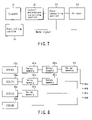
- FIG. 7 is a diagram showing a configuration of an image processing apparatus according to a second embodiment of the present invention.
- FIG. 8 is a diagram showing a detailed configuration of a scanner 31 ;
- FIG. 9 is a diagram showing a detailed configuration of a color/monochrome converting section 32 ;
- FIG. 10 is a graph showing a spectral sensitivity of a CCD of the scanner 31 ;
- FIG. 11 shows setting of a selector 54
- FIGS. 12A to 12G explain the detail of characteristics concerning a result processed by the image processing apparatus in the second embodiment of the present invention.
- FIG. 13 is a diagram showing a configuration of an image processing apparatus according to a third embodiment of the present invention.
- FIG. 14 is a diagram showing a detailed configuration of a scanner 61 ;
- FIG. 15A is a characteristic graph of a monochrome image signal
- FIG. 15B is a characteristic graph of a color image signal
- FIG. 16 is a diagram showing a detailed configuration of a memory 63 ;
- FIG. 17 is a diagram showing a detailed configuration of a color/monochrome determining section 62 ;
- FIG. 18 is a diagram showing a configuration of an image processing apparatus according to a fourth embodiment of the present invention.
- FIG. 19 is a diagram showing a detailed configuration of a compressing section 102 ;
- FIG. 20 is a diagram showing a detailed configuration of a luminance converting section 110 a;
- FIGS. 21A to 21J explain the detail of characteristics concerning a result processed by the image processing apparatus in the fourth embodiment of the present invention.
- FIG. 22 is a diagram showing a detailed configuration of a decoding circuit adopting a principle of the present invention.
- FIG. 1 shows a configuration of an image processing apparatus according to the first embodiment of the present invention.
- the image processing apparatus comprises a scanner 1 , a color/monochrome converting section 2 , a color converting section 3 , a printer 4 , and a controlling section 5 .
- color/monochrome conversion means conversion from color to monochrome.
- the scanner 1 picks up an image of an original document and outputs color image signals of RGB.
- the color/monochrome converting section 2 receives an input of the color image signal and outputs any one of the color image signal and a monochrome image signal generated from the color image signal to the color converting section 3 at a latter stage on the basis of a mode signal from the controlling section 5 .
- the mode signal means a signal for selecting one of a color mode output and a monochrome mode output.
- the color converting section 3 outputs the color image signal to the printer 4 after converting the signal into a CMYK signal.
- the color converting section 3 outputs the monochrome image signal to the printer 4 .
- a predetermined printing process based on the CMYK signal or the monochrome image signal is executed.
- the color image signal from the scanner 1 is converted into the monochrome image signal in the color/monochrome converting section 2 . Then, the monochrome image signal is sent to the printer 4 through the color converting section 3 . Then, the printing based on the monochrome image signal is executed in the printer 4 .
- FIG. 2 shows a detailed configuration of the scanner 1 .
- the scanner 1 is composed of a CCD(R) 11 a , CCD(G) 11 b , and CCD(B) 11 c corresponding to the respective colors of RGB, and delay memories 12 a , 12 b , and 13 . That is, the output from the CCD(R) 11 a is connected to an output port 14 a via delay memories 12 a and 13 . The output from the CCD(G) 11 b is connected to an output port 14 b via the delay memory 12 b . Moreover, the output from the CCD(B) 11 c is connected to an output port 14 c.
- the image signals of RGB from the CCD(R) 11 a , CCD(C) 11 b , and CCD(B) 11 c corresponding to the respective colors of RGB are output from the output ports 14 a , 14 b and 14 c after positions among the CCDs 11 a , 11 b , and 11 c are corrected by the delay memories 12 a , 12 b , and 13 .
- the image processing apparatus outputs regarding white and black to be 0 and 255, respectively.
- the color/monochrome converting section 2 is composed of comparators 15 a , 15 b , and 15 c , average operators 16 a and 16 b , and selectors 17 and 18 .
- the comparator 15 a compares the image signal of R with the image signal of G. Then, when a difference between them is greater than a threshold value S 1 , 1 is output, and otherwise, 0 is output at 20 a .
- the comparator 15 b compares the image signal of G with a threshold value S 2 . Then, when the image signal of G is greater than the threshold value S 2 , 1 is output, and otherwise, 0 is output 20 b .
- the comparator 15 c compares the image signal of G with the image signal of B. Then, when the difference between them is greater than a threshold value S 3 , 1 is output, and otherwise, 0 is output at 20 c.
- the average operator 16 a calculates an average value between the image signal of R and the image signal of G.
- the average operator 16 b calculates an average value between the image signal of G and the image signal of B.
- the selector 17 selects any one of the output signals from the average operators 16 a and 16 b and the image signal of G. In this manner, the selector 18 outputs, at 19 , the output signal from the selector 17 and the image signals of RGB by switching them on the basis of the mode signal from the controlling section 5 .
- the CCD(R) 11 a , CCD(G) 11 b , and CCD(B) 11 c of the scanner 1 have spectral sensitivity as shown in FIG. 4A .
- a horizontal axis indicates a wave length and a vertical axis indicates sensitivity in FIG. 4A .
- FIG. 5G shows a processed result of the case where the threshold values S 1 to S 3 are set to be 100 , and the selector 17 is set as shown in FIG. 6 .
- an original document being an object has a red area and an area with a black line in a part thereof.
- the image signals of RGB acquired as a result of picking up the image of such an original document by the respective CCD(R) 11 a , CCD(G) 11 b , and CCD(B) 11 c of RGB are as shown in FIGS. 5B , 5 C, and 5 D.
- the output of the average operator 16 a is selected as the output corresponding to the red area of the original document since the output of the image signal of R is large and the difference between the output of the image signal R and the output of the image signal of G is 150 as shown in FIG. 5G .
- the color image signal is adaptively switched and used as the monochrome image signal, and the monochrome image is printed and outputted so that monochrome image quality is improved.
- the color image signals are not limited to this.
- the image signals weighted to the respective values of RGB may be used, and needless to say, the switching method is also not limited to the one above.
- FIG. 7 shows a configuration of an image processing apparatus according to the second embodiment of the present invention.
- the image processing apparatus comprises a scanner 31 , a color/monochrome converting section 32 , a color converting section 33 , a printer 34 , and a controlling section 35 .
- the second embodiment is to acquire color and monochrome outputs by using the scanner 31 that can input a color signal and a monochrome signal at the same time. Then, a basic configuration thereof is similar to that of the first embodiment above except that the scanner 31 and the color/monochrome converting section 32 are changed so that repeated explanations are omitted here.
- FIG. 8 shows a detailed configuration of the scanner 31 .
- the scanner 31 is newly added with a CCD(K) 40 a for monochrome, and has a configuration that can extract a color signal and a monochrome signal at the same time.
- the output from the CCD(K) 40 a is connected to an output port 44 a via delay memories 41 a , 42 a , and 43 .
- An output from a CCD(R) 40 b is connected to an output port 44 b via delay memories 41 b and 42 b .
- An output from a CCD(G) 40 c is connected to an output port 44 c via a delay memory 41 c .
- an output from a CCD(B) 40 d is connected to an output port 44 d.
- the monochrome image signals from the respective CCD(K) 40 a , CCD(R) 40 b , CCD(G) 40 c , and CCD(B) 40 d , and the image signals of RGB are output from the output ports 44 a to 44 d after positional correction by the delay memories 41 a , 41 b , 41 c , 42 a , 42 b , and 43 .
- the color/monochrome converting section 32 is composed of a comparator 52 , average operators 50 and 51 , and selectors 53 and 54 .
- the average operator 50 calculates an average of the image signals of RGB. Then, the average operator 51 calculates an average between the signal relating to the average of the image signals of RGB and the image signal of K.
- the comparator 52 compares the signal relating to the average of the image signals of RGB and the output signal from the average operator 51 with threshold values S 4 and S 5 , and it executes predetermined output on the basis of the compared result.
- the selector 53 outputs the signal relating to the average of the image signals of RGB and the image signal of K, and the image signal K by adaptively switching them on the basis of the output signal from the comparator 52 .
- the selector 54 switches the image signal from the selector 53 and the image signals of RGB on the basis of the mode signal from the controlling section 5 and outputs them as image signals at 55 .
- the CCDs 40 a to 40 d of the scanner 31 have the spectral sensitivity as shown in FIG. 10 .
- a horizontal axis indicates a wave length and a vertical axis indicates a sensitivity in FIG. 4A .
- the CCD(K) 40 a for monochrome covers spectral ranges of the CCDs 40 b to 40 d for color in general, the spectral sensitivity is different in each wave length area.
- the ranges of the CCDs 40 b to 40 d for color are standardized for each sensor.
- the CCD(K) 40 a for monochrome is standardized by the color with the best spectral sensitivity (G in the example). Therefore, even if the sensitivity of the CCD(K) 40 a for monochrome and of the CCDs 40 b to 40 d for color are the same, the outputs from them in the same wave length area are different from each other. Owing to this, concerning the outputs from the CCD when, for example, a red original document is picked up, the output from the CCD(K) 40 a is lower than that of the output from the CCD(R) 40 b.
- the signal relating to the RGB average is converted into the image signal of K and is selectively output. This is a characteristic point of the second embodiment.
- FIG. 12G shows a processed result of the case where the threshold values S 4 and S 5 are set to be 0 and 100 respectively, and the selector 54 is set as shown in FIG. 11 .
- an original document being an object has a red area and an area with a black line in a part thereof.
- the image signals acquired as a result of picking up the original document by the respective CCD(R) 40 b , CCD(G) 40 c , and CCD(B) 40 d of RGB and CCD(K) 40 a of K are shown in FIGS. 12B to 12E .
- FIG. 12F when only the image signal of K is used, the output corresponding to the red area of the original document becomes low so that it is inadequate. When the present invention is applied, the output corresponding to the red area of the original document becomes high.
- the monochrome image signal and the color image signal are adaptively switched and used when the monochrome image signal is generated so that the monochrome image quality is improved.
- FIG. 13 shows a configuration of an image processing apparatus according to the third embodiment of the present invention.
- the image processing apparatus comprises a scanner 61 , a color/monochrome determining section 62 , a memory 63 , a color converting section 64 , a color resolution converting section 65 , and a printer 66 .
- color/monochrome determination means determination between color and monochrome.
- FIG. 14 shows a configuration of the scanner 61 .
- the scanner 61 can input a color signal and a monochrome signal at the same time.
- the scanner 61 is different from the scanner 31 in that a main scanning resolution of the color signal is 1 ⁇ 2 of that of the monochrome signal, and it has signal converting sections 72 a to 72 d for converting a bit number from 10 bits to 8 bits.
- the resolution for color is half of the resolution for monochrome. Therefore, if the resolution for monochrome is the same as that of the scanner 31 , half of the capacities of the delay memories 41 a to 41 c , 42 a , 42 b and 43 in FIG. 8 are sufficient as capacities of delay memories 73 a to 73 c , 74 a , 74 b , and 75 .
- the delayed signals are output to output ports 76 a to 76 d , respectively, as shown in FIG. 14 .
- the signal converting sections 72 a to 72 d execute logarithmic conversion concerning the image signals of RGB from CCDs 71 b to 71 d and execute conversion of only the bit number concerning the monochrome image signal from a CCD(K) 71 a , and they output the signals.
- the logarithmic conversion is executed concerning the image signals of RGB since a resolution performance thereof in a high-density area is important.
- the conversion from 8 bits into 8 bits is executed since gradation is formed from a nonexisting signal like the characteristic in FIG. 15B so that there is a possibility that a gradation skip and the like is generated.
- both color signals and monochrome signals are stored in the memory 63 as shown in FIG. 16 .
- the color/monochrome determining section 62 has difference devices 81 a , 81 b , and 81 c , comparators 82 a , 82 b , and 82 c , a counter 83 , and a comparator 89 .
- the absolute values of the differences among the respective image signals of RGB are taken, and the differences are compared with the threshold values S 6 to S 8 . If the differences are large as a result of the comparison, 1 is output from the comparators 82 a , 82 b , and 82 c . When any one of the signals from the comparators 82 a , 82 b , and 82 c is 1, the counter 83 is counted-up.
- the original document is determined as color original document as a result of color/monochrome determination and 1 is output by comparator 89 at 85 .
- the counted-up value is below the threshold value S 9 , the original document is distinguished to be a monochrome original document and 0 is output by comparator 89 at 85 .
- the color converting section 64 executes the conversion from the image signals of RGB into the CMYK signal only when the result determined by a known color converting method is the color signal.
- the color resolution converting section 65 converts the resolution into the same resolution as the monochrome image signal by known linear interpolation. As clear from a flow of such a series of processes, basically, it is necessary to use all data of one screen in order to execute the color/monochrome determination.
- deterioration of the image quality during the monochrome process is reduced by, in the case where both the color signal and the monochrome signal can be input at the same time, storing both signals in the memory 63 .
- the resolution of the color image signal is lower than the resolution of the monochrome image signal so that the memory capacity for storing can also be reduced.
- FIG. 18 shows a configuration of an image processing apparatus according to the fourth embodiment of the present invention.
- the image processing apparatus comprises a scanner 101 , a compressing section 102 , a memory 103 , a decoding section 104 , a color converting section 105 , and a printer 106 .
- signal converting sections for color and monochrome inside the scanner 101 are set in the same manner.
- An image signal is compressed by the compressing section 102 and then, it is stored in the memory 103 .
- the processes are approximately the same as those in the third embodiment except that the processes thereafter are executed concerning the signal properly read out from the memory 103 and decoded by the decoding section 104 .
- the repeated explanations are omitted.
- FIG. 19 shows a detailed configuration of the compressing section 102 .
- the image signals of K and RGB are input to a luminance converting section 110 a .
- An output from the luminance converting section 110 a is connected to one input of a coding section 115 via a raster block converting section 111 a , a DCT 112 a , a quantization section 113 a , and a Huffman section 114 a .
- the image signals of RGB are input to a color difference converting section 110 b .
- An output from the color difference converting section 110 b is connected to one input of the coding section 115 via a raster block converting section 111 b , a DCT 112 b , a quantization section 113 b , and a Huffman section 114 b , and are connected to the other input of the coding section 115 via a raster block converting section 111 c , a DCT 112 c , a quantization section 113 c , and a Huffman section 114 c . Then, in such a configuration, the image is subjected to block resolution into a size of 8 ⁇ 8 by using known JPEG and is compressed for each luminance/color difference.
- the image quality of the color difference signal is good even in the lower resolution comparing with that of the luminance signal so that the color difference signal is compressed after the resolution is lowered.
- the color difference signal with the low resolution is generated by using the image signals of RGB with the low resolution in the known color difference converting section 110 b , and the luminance signal with the high resolution is generated and compressed from the monochrome signal with the high resolution and the image signals of RGB with the low resolution by using the luminance converting section 110 a shown in FIG. 20 .
- the luminance/color difference conversion and the inversion are executed by the following:
- an average value in 2-pixel unit and an absolute value of the difference between 2 pixels are calculated by using an average operator 120 and a difference section 125 after matching the monochrome image signal with the high resolution with the resolution of the color image signal at D-FF 113 . Then, the difference value is compared with a threshold value S 10 at a comparator 121 . As a result of the comparison, when the difference value is below the threshold value S 10 , 1 is output regarding the area to be flat, and otherwise, 0 is output to AND gate 132 .
- 0.25 ⁇ R+0.5 ⁇ G+0.25 ⁇ B is calculated by matching the average value of the three signals to a formula according to the conversion from RGB into YIQ at an average section 122 .
- the average value of the monochrome signals is compared with the average value of the color signals, determined using the average operator 122 , in the comparator 124 , and when the color average>monochrome average, 1 is output regarding the color is the color whose sensitivity is lowered at the sensor for monochrome, and otherwise, 0 is output at AND gate 123 .
- a difference value of the average value of the color signals is determined by a difference section 123 .
- K 1 and K 2 are the monochrome signal with the high resolution.
- the threshold value S 10 is assumed to be 200 .
- the luminance signal is generated by using the color image signal being the output from the CCD of RGB, and the monochrome image signal is used as it is as the luminance signal in an edge area.
- an original document being an object has a red area and a area with a black line in its part.
- the image signal acquired as a result of picking up the original document by the respective CCDs of RGB and K is shown in FIGS. 21B to 21E .
- FIG. 21F the image signal of the case where the average of RGB is taken is shown in FIG. 21F
- FIG. 21G the image signal of the case where the average of K is taken is shown in FIG. 21G
- FIG. 21H the image signal of the case where the difference of the average of K from the RGB average is taken is shown in FIG. 21H
- FIG. 21I the image signal of the case where the absolute value of the difference is taken is shown in FIG. 21I .
- the difference between the RGB average and the K average to which (K 1 , K 2 ) is added is adopted as the pixel corresponding to the red area of the original document, and (K 1 , K 2 ) is adopted as the pixel corresponding to the area with the black line.
- the monochrome image signal and the color image signal are adaptively switched and used when the monochrome image signal is generated so that the monochrome image quality is improved.
- the image processing apparatus that can input both the color signal and the monochrome signal at the same time and that converts the image signal from the color sensor with the low resolution into the luminance/color difference signal system and compresses it, memory cost for raster block conversion during the color conversion can be reduced, and a luminance signal and a color difference signal with high picture quality can be acquired even in the above-described device by adaptively generating the luminance signal by using both the monochrome image signal with high resolution and the color image signal with lower resolution.
- the known JPEG decoding process is executed on an input signal 200 via a decoding section 201 by using Huffman sections 202 a to 202 c , inverse quantization sections 203 a to 203 c , IDCTs 204 a to 204 c , and block raster converting sections 205 a to 205 c .
- the monochrome signal is output as it is at a luminance converting section 207 .
- the conversion from the color difference signal into the image signals of RGB is executed according to the formula relating to the conversion from the YIQ into RGB above at 208 , and the signal is output.
- the color image signal is used only when in the flat section and the output of the color image signal is larger than that of the monochrome image signal and the monochrome image signal is used as it is as the luminance signal otherwise.
- the generation of the luminance signal is not limited to this example, and switching may be executed in accordance with conditions such as color/black character determination or existence of a white-base area.
- the monochrome image signal may be used not only for the generation of the luminance signal but also for the generation of the color difference signal.
- the conversion from the luminance signal and the color difference signal into the color image signal and the monochrome image signal during decoding is not limited to this method.
- the conversion may adaptively be switched by using the color difference signal as well for the conversion into the monochrome image signal. The same applies to the conversion from the color difference signal into the color image signal.
- the resolution of the color sensor is different by twice in a main scanning direction from the resolution of the monochrome sensor is mentioned in the embodiments above, it is not limited to the example.
Abstract
Description
0.25×R+0.5×G+0.25×B
is calculated by matching the average value of the three signals to a formula according to the conversion from RGB into YIQ at an
K′, K″=(color average−monochrome average)+(K1, K2)
Claims (12)
Priority Applications (2)
| Application Number | Priority Date | Filing Date | Title |
|---|---|---|---|
| US10/054,990 US7190486B2 (en) | 2002-01-25 | 2002-01-25 | Image processing apparatus and image processing method |
| JP2002381813A JP4057416B2 (en) | 2002-01-25 | 2002-12-27 | Image processing apparatus and image processing method |
Applications Claiming Priority (1)
| Application Number | Priority Date | Filing Date | Title |
|---|---|---|---|
| US10/054,990 US7190486B2 (en) | 2002-01-25 | 2002-01-25 | Image processing apparatus and image processing method |
Publications (2)
| Publication Number | Publication Date |
|---|---|
| US20030142376A1 US20030142376A1 (en) | 2003-07-31 |
| US7190486B2 true US7190486B2 (en) | 2007-03-13 |
Family
ID=27609181
Family Applications (1)
| Application Number | Title | Priority Date | Filing Date |
|---|---|---|---|
| US10/054,990 Active 2024-10-24 US7190486B2 (en) | 2002-01-25 | 2002-01-25 | Image processing apparatus and image processing method |
Country Status (2)
| Country | Link |
|---|---|
| US (1) | US7190486B2 (en) |
| JP (1) | JP4057416B2 (en) |
Cited By (9)
| Publication number | Priority date | Publication date | Assignee | Title |
|---|---|---|---|---|
| US20040233476A1 (en) * | 2003-05-19 | 2004-11-25 | Kabushiki Kaisha Toshiba | Image processing apparatus and image processing method |
| US20050063013A1 (en) * | 2003-09-22 | 2005-03-24 | Xerox Corporation | Enhancing black & white image quality with limited image processing resources |
| US20060279748A1 (en) * | 2005-06-08 | 2006-12-14 | Kabushiki Kaisha Toshiba | Apparatus and method for compensating for resolution differences of color and monochrome sensors |
| US20070086068A1 (en) * | 2005-10-18 | 2007-04-19 | Satoshi Ohkawa | Image processing apparatus |
| US20070236706A1 (en) * | 2006-03-30 | 2007-10-11 | Kabushiki Kaisha Toshiba | Image data processing apparatus and method |
| US20080187243A1 (en) * | 2007-02-02 | 2008-08-07 | Kabushiki Kaisha Toshiba | Image reading apparatus and image reading method |
| US20080247008A1 (en) * | 2005-11-29 | 2008-10-09 | Oce-Technologies B.V. | Scanner and method of scanning |
| US8724894B1 (en) * | 2012-12-03 | 2014-05-13 | Rockwell Collins, Inc. | Colorization of digital imagery |
| US20140177013A1 (en) * | 2012-12-25 | 2014-06-26 | Konica Minolta, Inc. | Image forming apparatus, reading apparatus, and control method of reading |
Families Citing this family (13)
| Publication number | Priority date | Publication date | Assignee | Title |
|---|---|---|---|---|
| US20060044576A1 (en) * | 2004-07-30 | 2006-03-02 | Kabushiki Kaisha Toshiba | Apparatus for image processing |
| US7502063B2 (en) * | 2004-08-09 | 2009-03-10 | Aptina Imaging Corporation | Camera with scalable resolution |
| JP4522293B2 (en) * | 2005-03-15 | 2010-08-11 | 株式会社リコー | Image forming apparatus |
| US20060238830A1 (en) * | 2005-04-21 | 2006-10-26 | Peter Dikeman | Color image capture system |
| US7880925B2 (en) * | 2005-08-02 | 2011-02-01 | Kabushiki Kaisha Toshiba | Apparatus and method for generating an image file with a color layer and a monochrome layer |
| JP4568195B2 (en) * | 2005-08-30 | 2010-10-27 | 京セラミタ株式会社 | Image reading device |
| JP4791928B2 (en) * | 2006-09-28 | 2011-10-12 | 株式会社東芝 | Image processing apparatus and image processing method |
| US8750593B2 (en) * | 2006-11-07 | 2014-06-10 | Pitney Bowes Inc. | Substitute check incorporating encoded indication of security feature in original check |
| US20080187169A1 (en) * | 2007-02-02 | 2008-08-07 | Kabushiki Kaisha Toshiba | Image processing apparatus and image processing method |
| JP5039736B2 (en) * | 2009-03-24 | 2012-10-03 | キヤノン株式会社 | Image processing apparatus, control method, and program |
| JP5200073B2 (en) * | 2010-08-31 | 2013-05-15 | キヤノン株式会社 | Color image processing apparatus and program |
| JP5687560B2 (en) * | 2011-05-18 | 2015-03-18 | 株式会社沖データ | Image processing apparatus and program, and image forming apparatus |
| JP5649683B2 (en) * | 2013-04-01 | 2015-01-07 | キヤノン株式会社 | Printing apparatus, printing method, and program |
Citations (15)
| Publication number | Priority date | Publication date | Assignee | Title |
|---|---|---|---|---|
| JPH02144567A (en) | 1988-11-26 | 1990-06-04 | Konica Corp | Color image processor |
| JPH05153405A (en) | 1991-03-27 | 1993-06-18 | Samsung Electron Co Ltd | System and device for compressing digital image data |
| JPH05207306A (en) * | 1992-01-29 | 1993-08-13 | Sharp Corp | Picture reader |
| US5357354A (en) * | 1988-11-26 | 1994-10-18 | Konica Corporation | Color image processing apparatus capable of discriminating between a monochromatic document and a color document |
| JPH0795416A (en) | 1993-09-21 | 1995-04-07 | Fuji Xerox Co Ltd | Encoding device for picture signal |
| US5973802A (en) * | 1995-03-07 | 1999-10-26 | Minolta Co., Ltd. | Image reproducing apparatus for forming either of a color image or a monochromatic image |
| US5999644A (en) * | 1989-10-31 | 1999-12-07 | Canon Kabushiki Kaisha | Image processing apparatus and method |
| US6115150A (en) * | 1996-02-20 | 2000-09-05 | Mita Industrial Co., Ltd. | Image data processing apparatus and image data processing process |
| US6762863B1 (en) * | 1999-11-12 | 2004-07-13 | Minolta Co., Ltd. | Film scanning system |
| US6765703B1 (en) * | 2000-09-27 | 2004-07-20 | Kabushiki Kaisha Toshiba | Method and apparatus for sensing image |
| US20040156076A1 (en) * | 2002-09-17 | 2004-08-12 | Atsushi Togami | Method of and apparatus for image processing, and computer product |
| US20040257621A1 (en) * | 2003-04-11 | 2004-12-23 | Hiroshi Ishihara | Method, apparatus, and program for image processing capable of producing high-quality achromatic colored output image, and medium storing the program |
| US20050219661A1 (en) * | 2004-04-01 | 2005-10-06 | Kabushiki Kaisha Toshiba | Image forming apparatus, image forming method, and program |
| US20050243347A1 (en) * | 2004-03-08 | 2005-11-03 | Ikuo Hayaishi | Conversion of color image to monochrome image |
| US7006708B1 (en) * | 1998-06-23 | 2006-02-28 | Sharp Kabushiki Kaisha | Image processor, image processing method, and medium on which image processing program is recorded |
-
2002
- 2002-01-25 US US10/054,990 patent/US7190486B2/en active Active
- 2002-12-27 JP JP2002381813A patent/JP4057416B2/en not_active Expired - Fee Related
Patent Citations (18)
| Publication number | Priority date | Publication date | Assignee | Title |
|---|---|---|---|---|
| US5357354A (en) * | 1988-11-26 | 1994-10-18 | Konica Corporation | Color image processing apparatus capable of discriminating between a monochromatic document and a color document |
| JPH02144567A (en) | 1988-11-26 | 1990-06-04 | Konica Corp | Color image processor |
| US5999644A (en) * | 1989-10-31 | 1999-12-07 | Canon Kabushiki Kaisha | Image processing apparatus and method |
| JPH05153405A (en) | 1991-03-27 | 1993-06-18 | Samsung Electron Co Ltd | System and device for compressing digital image data |
| US5293252A (en) | 1991-03-27 | 1994-03-08 | Samsung Electronics Co., Ltd. | Method of compressing digital image data and device thereof |
| JPH05207306A (en) * | 1992-01-29 | 1993-08-13 | Sharp Corp | Picture reader |
| US6118552A (en) | 1993-09-21 | 2000-09-12 | Fuji Xerox Co., Ltd. | Image signal encoding apparatus |
| JPH0795416A (en) | 1993-09-21 | 1995-04-07 | Fuji Xerox Co Ltd | Encoding device for picture signal |
| US5861960A (en) | 1993-09-21 | 1999-01-19 | Fuji Xerox Co., Ltd. | Image signal encoding apparatus |
| US5973802A (en) * | 1995-03-07 | 1999-10-26 | Minolta Co., Ltd. | Image reproducing apparatus for forming either of a color image or a monochromatic image |
| US6115150A (en) * | 1996-02-20 | 2000-09-05 | Mita Industrial Co., Ltd. | Image data processing apparatus and image data processing process |
| US7006708B1 (en) * | 1998-06-23 | 2006-02-28 | Sharp Kabushiki Kaisha | Image processor, image processing method, and medium on which image processing program is recorded |
| US6762863B1 (en) * | 1999-11-12 | 2004-07-13 | Minolta Co., Ltd. | Film scanning system |
| US6765703B1 (en) * | 2000-09-27 | 2004-07-20 | Kabushiki Kaisha Toshiba | Method and apparatus for sensing image |
| US20040156076A1 (en) * | 2002-09-17 | 2004-08-12 | Atsushi Togami | Method of and apparatus for image processing, and computer product |
| US20040257621A1 (en) * | 2003-04-11 | 2004-12-23 | Hiroshi Ishihara | Method, apparatus, and program for image processing capable of producing high-quality achromatic colored output image, and medium storing the program |
| US20050243347A1 (en) * | 2004-03-08 | 2005-11-03 | Ikuo Hayaishi | Conversion of color image to monochrome image |
| US20050219661A1 (en) * | 2004-04-01 | 2005-10-06 | Kabushiki Kaisha Toshiba | Image forming apparatus, image forming method, and program |
Non-Patent Citations (1)
| Title |
|---|
| U.S. Appl. No. 09/955,312, filed Sep. 19, 2001, Tabata et al. |
Cited By (16)
| Publication number | Priority date | Publication date | Assignee | Title |
|---|---|---|---|---|
| US8035870B2 (en) | 2003-05-19 | 2011-10-11 | Kabushiki Kaisha Toshiba | Image processing apparatus and image processing method |
| US7463393B2 (en) * | 2003-05-19 | 2008-12-09 | Kabushiki Kaisha Toshiba | Image processing apparatus and image processing method |
| US20090080008A1 (en) * | 2003-05-19 | 2009-03-26 | Kabushiki Kaisha Toshiba | Image processing apparatus and image processing method |
| US20040233476A1 (en) * | 2003-05-19 | 2004-11-25 | Kabushiki Kaisha Toshiba | Image processing apparatus and image processing method |
| US20050063013A1 (en) * | 2003-09-22 | 2005-03-24 | Xerox Corporation | Enhancing black & white image quality with limited image processing resources |
| US20060279748A1 (en) * | 2005-06-08 | 2006-12-14 | Kabushiki Kaisha Toshiba | Apparatus and method for compensating for resolution differences of color and monochrome sensors |
| US20070086068A1 (en) * | 2005-10-18 | 2007-04-19 | Satoshi Ohkawa | Image processing apparatus |
| US20080247008A1 (en) * | 2005-11-29 | 2008-10-09 | Oce-Technologies B.V. | Scanner and method of scanning |
| US7969626B2 (en) * | 2005-11-29 | 2011-06-28 | Oce-Technologies B.V. | Scanner and method of scanning |
| US20070236706A1 (en) * | 2006-03-30 | 2007-10-11 | Kabushiki Kaisha Toshiba | Image data processing apparatus and method |
| US7719711B2 (en) | 2006-03-30 | 2010-05-18 | Kabushiki Kaisha Toshiba | Image data processing apparatus and method |
| US7929806B2 (en) * | 2007-02-02 | 2011-04-19 | Kabushiki Kaisha Toshiba | Image reading apparatus and image reading method |
| US20080187243A1 (en) * | 2007-02-02 | 2008-08-07 | Kabushiki Kaisha Toshiba | Image reading apparatus and image reading method |
| US8724894B1 (en) * | 2012-12-03 | 2014-05-13 | Rockwell Collins, Inc. | Colorization of digital imagery |
| US20140177013A1 (en) * | 2012-12-25 | 2014-06-26 | Konica Minolta, Inc. | Image forming apparatus, reading apparatus, and control method of reading |
| US9019573B2 (en) * | 2012-12-25 | 2015-04-28 | Konica Minolta, Inc. | Image forming apparatus, reading apparatus, and control method of reading |
Also Published As
| Publication number | Publication date |
|---|---|
| JP2003224731A (en) | 2003-08-08 |
| US20030142376A1 (en) | 2003-07-31 |
| JP4057416B2 (en) | 2008-03-05 |
Similar Documents
| Publication | Publication Date | Title |
|---|---|---|
| US7190486B2 (en) | Image processing apparatus and image processing method | |
| US5861960A (en) | Image signal encoding apparatus | |
| KR960005016B1 (en) | Printing color control method and circuit in cvp | |
| US5345517A (en) | Image reduction apparatus | |
| US6995794B2 (en) | Video camera with major functions implemented in host software | |
| US6215904B1 (en) | Apparatus and method for selecting encoding schemes based upon image content | |
| US8606003B2 (en) | Image processing device, image processing method and image processing program | |
| US5371606A (en) | Image encoding apparatus | |
| JPS59223073A (en) | Picture processor | |
| US8437043B2 (en) | Compression of grayscale image data using multi-bit halftoning | |
| US4688100A (en) | Video data encoding/decoding apparatus | |
| US5442459A (en) | Process for encoding a half tone image considering similarity between blocks | |
| US5245444A (en) | Image reproduction using error diffusion or dither matrix | |
| US7339703B2 (en) | Image processing apparatus and method thereof | |
| US20060001921A1 (en) | System and method for high-performance scanner calibration | |
| US5452107A (en) | Image processing apparatus providing a bilevel image signal by changing binarization threshold value based on densities of original image areas incuding target pixel and less than all surrounding pixels | |
| US5471319A (en) | Image processing method and image processing apparatus | |
| USRE38177E1 (en) | Image processing apparatus for changing the resolution upon rotation of the image | |
| US20020063899A1 (en) | Imaging device connected to processor-based system using high-bandwidth bus | |
| US7139442B2 (en) | Template matching applied to selector planes for multiple raster content (MRC) representation of documents | |
| US7430342B2 (en) | Image processing apparatus and image processing program to perform image data resolution conversion | |
| US6879417B1 (en) | Color image processing apparatus that performs color conversion processing | |
| JPH04238462A (en) | Picture processor | |
| US20030053703A1 (en) | Image compression decoding apparatus and method thereof | |
| JP3265100B2 (en) | Facsimile machine |
Legal Events
| Date | Code | Title | Description |
|---|---|---|---|
| AS | Assignment |
Owner name: TOSHIBA TEC KABUSHIKI KAISHA, JAPAN Free format text: ASSIGNMENT OF ASSIGNORS INTEREST;ASSIGNORS:TABATA, SUNAO;KANNO, HIROKI;REEL/FRAME:012522/0946 Effective date: 20020115 |
|
| AS | Assignment |
Owner name: KABUSHIKI KAISHA TOSHIBA, JAPAN Free format text: ASSIGNMENT (ONE-HALF INTEREST);ASSIGNOR:TOSHIBA TEC KABUSHIKI KAISHA;REEL/FRAME:014118/0099 Effective date: 20030530 Owner name: TOSHIBA TEC KABUSHIKI KAISHA, JAPAN Free format text: ASSIGNMENT (ONE-HALF INTEREST);ASSIGNOR:TOSHIBA TEC KABUSHIKI KAISHA;REEL/FRAME:014118/0099 Effective date: 20030530 |
|
| STCF | Information on status: patent grant |
Free format text: PATENTED CASE |
|
| FPAY | Fee payment |
Year of fee payment: 4 |
|
| FPAY | Fee payment |
Year of fee payment: 8 |
|
| MAFP | Maintenance fee payment |
Free format text: PAYMENT OF MAINTENANCE FEE, 12TH YEAR, LARGE ENTITY (ORIGINAL EVENT CODE: M1553); ENTITY STATUS OF PATENT OWNER: LARGE ENTITY Year of fee payment: 12 |