US7193633B1 - Method and apparatus for image assisted modeling of three-dimensional scenes - Google Patents
Method and apparatus for image assisted modeling of three-dimensional scenes Download PDFInfo
- Publication number
- US7193633B1 US7193633B1 US09/562,212 US56221200A US7193633B1 US 7193633 B1 US7193633 B1 US 7193633B1 US 56221200 A US56221200 A US 56221200A US 7193633 B1 US7193633 B1 US 7193633B1
- Authority
- US
- United States
- Prior art keywords
- dimensional
- primitives
- parameters
- primitive
- constraint
- Prior art date
- Legal status (The legal status is an assumption and is not a legal conclusion. Google has not performed a legal analysis and makes no representation as to the accuracy of the status listed.)
- Expired - Fee Related
Links
Images


Classifications
-
- G—PHYSICS
- G06—COMPUTING; CALCULATING OR COUNTING
- G06T—IMAGE DATA PROCESSING OR GENERATION, IN GENERAL
- G06T17/00—Three dimensional [3D] modelling, e.g. data description of 3D objects
- G06T17/10—Constructive solid geometry [CSG] using solid primitives, e.g. cylinders, cubes
Definitions
- the present invention relates to the fields of photogrammetry and computer-assisted three-dimensional modeling.
- the present invention relates to the determination of camera parameters, and locations and dimensions of objects as seen in one or more digital representations of photographs or images.
- the aim of photogrammetric methods and systems is to provide precise measurements of real world objects.
- stereoscopic cameras and reconstruction workstations have been developed. They often require specific (i.e., calibrated) cameras with known focal lengths, optical and spatial separations, projections, and other characteristics to allow accurate reconstruction on the camera parameters.
- some conventional photogrammetric techniques require that one or more points in the “scene” shown in the photographs have locations or inter-point distances which are known in advance. This can be very difficult, as it may require access to the exterior of buildings, landmarks, or other structures which may be impossible.
- photogrammetric schemes of the past typically do not provide outputs in the form of complete three dimensional models and rarely, if ever, provide any texturing information for objects in a scene.
- Three-dimensional modeling applications have as a primary objective the production of such models.
- the need for such techniques is felt in a number of ways. For example, it is often desirable to have a three-dimensional model, complete with a description of shape, location, orientation, and material surface properties (i.e., texture), in order to produce realistic renderings on a computer which can be used to document a new design of a city, a building, or an object.
- the model can also be used for computer animations, virtual reality immersion of users in a scene, or for manufacturing tasks.
- the shape in terms of the form of points on the surface of the object to be modeled, the object's location, size and orientation, and often its spatial relationship to other objects in the scene must all be known before a user begins to create the model.
- an object to be modeled does not yet exist in the real world, such as is the case with, say, a new building or interior design, the only way to create the scene is with a model. But, in many cases, other buildings, mechanisms, or environments into which the new design will be introduced already exist and must be accounted for in the model. The previous modeling techniques thus require a great deal of measuring, data entry, and checking before the model can be created.
- this software package allowed a user to first create a model of a scene using conventional computer-modeling techniques and then, as a post-process, allowed for positioning a primitive on top of a photograph underlaid in the model.
- a camera was roughly matched and the previously created three-dimensional model could be rendered superimposed on top of the photograph with correct perspective. No modeling was done from the photograph nor was the camera model very precise.
- previous approaches to the modeling problem also often involve algorithms that run in “batch” mode. That is, a user must create all of the input data (e.g., vertices, edges, associations, etc.) and then invoke the modeling method. The modeling algorithms then complete all of the required calculations before providing any feedback to the user. Sometimes, because of inconsistent or undetermined input information, or due to singularities in the modeling algorithms themselves, these batch processes cannot return correct or even useful models. Even worse, such algorithms often provide little or no indication of what the cause of the problem was, or where the user might correct the input information to resubmit to the batch process.
- 3D Builder available from 3D Construction Company
- 3D Construction Company allows modeling of complex curved surfaces (e.g., human faces) but requires that users mark many points on the real world object to be modeled before taking a photograph thereof.
- a point is created in the model for each marked point on each photograph and the corresponding points in the different photographs must be associated with one another in the model.
- edges can be constructed between the points and faces created between the edges. This is a very labor intensive process and requires the use of a number of “atomic” entries (the points) to achieve high accuracy.
- Only after all of the points, edges and faces have been created does the modeling process run in a batch mode (as opposed to a user interactive mode) to (hopefully) generate the resulting three-dimensional model.
- one object of the present invention is to provide an improved computer-assisted technique for constructing a three-dimensional model on top of one or more images (e.g., photographs) such that the model's parameters automatically match those of the real world object depicted in the photograph(s).
- images e.g., photographs
- a further object of the present invention is to provide an improved technique for determining, from each of one or more photographs, the camera parameters such as focal length, position, and orientation in space such that the projection of a three-dimensional model through the calculated camera parameters matches the projection of the real world object through the camera onto the surface of the one or more photographs.
- a still further objective of the present invention is to provide an improved technique for geometric modeling in terms of primitives, such as boxes or pyramids, rather than vertices, edges or faces which reduces the amount of locational and/or associational data a user needs to provide.
- the improved technique requires only a single step, rather than separate and multiple modeling and associational steps as required in schemes of the past, to construct three-dimensional models from one or more photographs.
- Another objective of the present invention is to provide an improved (over schemes of the past) technique for intuitively manipulating primitives which are used to construct three-dimensional models on a video display or other display screen of a computer system with two-dimensional input controllers (e.g., a mouse, joystick) such that the displayed three-dimensional object manipulation emulates physical three-dimensional object manipulation.
- two-dimensional input controllers e.g., a mouse, joystick
- a still further objective of the present invention is to provide an improved technique for incrementally updating the parameters and to provide visual feedback of the updated parameters of a three-dimensional model to a user, making it readily apparent which user action was responsible for any failure to provide a modeling solution and, thus, allowing for rapid reversal and correction thereof.
- Yet another objective of the present invention is to provide an improved technique for automatically extracting surface properties (i.e., textures), such as color, from a source photograph for use in a three-dimensional model of a scene produced therefrom and to combine such properties so that partial occlusions are successively eliminated from the model.
- surface properties i.e., textures
- a computer-assisted method which, in one embodiment, allows for manipulating a multitude of objects displayed in a three-dimensional representation on a computer controlled display system having a computer and a display coupled to the computer, the method comprising the steps of displaying one or more digital representations of photographs, selecting one of the representations of the photographs, creating three-dimensional primitives from a variety of available primitives, providing a user actuated input controller for selectively positioning a reference indicator over the displayed projection of the primitive and signaling the computer to activate a constraint placement mode, optionally providing a visual feedback of the constraint placement mode, signaling the computer to create the constraint, and incrementally calculating primitive and camera parameters based on the new constraint, providing immediate visual feedback as the parameters are updated in accordance with the new constraint, repositioning the reference indicator to define a movement of the constraint and providing immediate visual feedback as the constraint is moved and the parameters are updated in accordance with the new constraint location.
- a parameterized three-dimensional model may be constructed on top of one or more digital images, the parameters of the three-dimensional model corresponding to parameters of real-world objects depicted in the one or more images.
- the one or more digital images may be derived from one or more photographs, for example, digital photographs or scanned representations of photographs.
- the three-dimensional model includes one or more geometric primitives, for example, boxes or pyramids. The geometric primitives may be textured, with surface properties therefor being extracted from the digital images.
- a computer-based model having one or more virtual cameras with parameters determined from a digital representation of one or more images derived from one or more real-world cameras.
- a projection of the computer-based model through the parameters of the one or more virtual cameras approximates the projection of one or more real-world objects depicted in the digital representations of the one or more images as seen through the one or more real-world cameras.
- the parameters of the one or more virtual cameras may include focal length, position, or orientation in space.
- a further embodiment of the present invention provides a computer-based model which includes a representation of a three-dimensional geometric primitive overlaid on a digital representation of an image having an object shown therein.
- the primitive is constrained to at least one feature of the object shown within the digital representation of the image and the digital representation of the image may be derived from a photograph.
- the three-dimensional geometric primitive may be chosen from a variety of available primitives and the digital representation of the image selected from a plurality of available images.
- visual feedback of the constrained representation of the three-dimensional geometric primitive is provided to a user and updated sufficiently to provide the user with immediate feedback regarding changes and/or additions of constraints.
- the present invention includes a computer-based model which includes a parametric scene having estimated parameters and being interactively and incrementally created directly on top of a displayed digital representation of an image.
- the parametric scene may include one or more three-dimensional, parameterized geometric primitives and a parameterized virtual camera with the geometric primitives constrained to correspond to one or more objects depicted in the digital representation of the image.
- the digital representation of the image is continuously displayed as representations (e.g., wireframes) of the one or more geometric primitives that are superimposed thereon.
- the primitives may be simple primitives, such as boxes, pyramids, cylinders, linear extrusions, or rotation symmetric objects; compound primitives; or imported primitives and are constrained using one or more vertex constraints, edge constraints, glue constraints, measurement constraints, on-face constraints, on-top constraints, align orientation constraints, linear align constraints, equidistant constraints, or shared parameter constraints.
- the glue constraints may be point-to-point constraints, point-to-edge constraints, or edge-to-edge constraints.
- the measurement constraints may be length constraints, direction constraints, or datum constraints.
- FIG. 1 depicts a generalized block diagram of a computer system as might be used by the present invention
- FIG. 2 illustrates the visual feedback provided by the present invention, including a user-supplied image overlaid with a wireframe of a primitive and constraints;
- FIG. 3 illustrates a variety of primitives with their local coordinate systems for use with and according to the present invention
- FIG. 4 is a flowchart illustrating the sequence of steps involved in creating a three-dimensional model according to one embodiment of the present invention
- FIG. 5 illustrates a variety of constraint types and their visual feedback provided according to various embodiments of the present invention
- FIG. 6 illustrates further constraint types and their visual feedback provided in accordance with yet further embodiments of the present invention.
- FIG. 7 illustrates the use of constraints to align wireframe representations of primitives to objects in a digital image in accordance with the present invention.
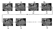
- FIG. 8 illustrates the creation of a three-dimensional model representing the scene(s) captured in one or more images in accordance with the present invention.
- Described herein is a computer-assisted technique for constructing a three-dimensional model on top of one or more images such that the model's parameters automatically match those of real world object depicted in the images.
- the present invention generally involves loading digital images acquired from scanners or digital cameras and the manipulation of computer displayed objects represented in three-dimensional form, and so it may be helpful to provide a brief description of the relevant components of such a computing environment.
- FIG. 1 is a generalized block diagram of a computer system 10 which includes a central processing unit (CPU) 11 .
- CPU 11 generally includes one or more general purpose processors and one or more memory units, usually in the form of read/write memory (RAM) and/or read only memory (ROM).
- Application programs such as may comprise one embodiment of the present invention, may be loaded into RAM (e.g., from another storage medium) for execution by one or more of the general purpose processors which comprises CPU 11 .
- computer readable instructions which comprise an embodiment of the present invention may be stored in ROM or other non-volatile media, or downloaded from a source of such instructions (e.g., via a computer network and/or the network of networks commonly referred to as the Internet) for execution by CPU 11 .
- Computer system 10 also includes a keyboard or other alphanumeric input device 12 which is coupled to (e.g., via one or more busses) and provides user input to CPU 11 as does a two-dimensional input controller 13 .
- Two-dimensional input controller 13 may, by way of example, be a mouse, trackball, stylus or other input device.
- Images may be provided to CPU 11 via image scanning device 17 , video capture device 18 (e.g., which is able to extract still images from a video signal) and/or digital camera 16 , each or any of which may be coupled to CPU 11 via one or more connectors and/or busses.
- Disk drive unit(s) 15 may also be coupled to CPU 11 and may be used for storing the digital images, and geometric and texture data generated by the present invention as well as computer readable instructions which comprise an embodiment of the present invention.
- Display output is provided by a video display unit 14 coupled to CPU 11 .
- Video display unit 14 may be a conventional display such as a liquid crystal display (LCD) or other display device.
- Digital images can be created by scanning existing photographs or printed material into the computer system 10 and storing the same in memory or on disk drive 15 . This may be accomplished, for example, using a software application which, when executed by CPU 11 , allows still images to be captured from a video (e.g., as a frame of the video) and stored to memory. Alternatively, the output of digital camera 16 or scanner 17 may be downloaded to memory and/or long term storage. In this way, one or more digital images may be stored and later used by a software application which is one embodiment of the present invention.
- FIG. 2 now illustrates a general method of creating a digital model using the methods of the present invention.
- a user may then create one or more objects known as primitives (e.g., boxes, pyramids, cylinders, or other three-dimensional objects) which approximate the objects shown in the digital images (step 251 ).
- a wireframe rendering 202 of the primitives may be displayed over top of the digital image 201 (i.e., the digital representation of the photograph).
- the objective is for the user to manipulate the wireframe primitive rendering 202 using the methods of the present invention, until the wireframe precisely (or nearly precisely) coincides with the object it represents in the digital image (steps 252 , 253 , 254 , 255 and 256 ).
- the user creates a geometric model (from the primitive(s)) right on top of the digital image 201 (i.e., the photograph(s)), without requiring the use of separate editors, windows or views.
- a wireframe rendering 202 of a rectilinear box is manipulated until it coincides with the outline of a box shown in the digital image 201 .
- the two-dimensional wireframe rendering 202 of the primitive may be created from its predefined three-dimensional representation by projecting the geometry of the primitive through a virtual camera.
- parameters for the virtual camera such as position, orientation, focal length, etc., are found (e.g., as the wireframe primitive representation 202 is aligned with the object it represents in the digital image 201 ) such that projection through the virtual camera yields the same two-dimensional projected geometry as is visible in the underlaid digital image (i.e., the underlaid photograph) 201 .
- multiple virtual cameras e.g., one for each image
- parameters for each of the primitives e.g., length, width, height, orientation, and location in space
- constraints are added to “fix” the wireframe 202 to the image 201 .
- constraints 703 , 704 which constrain or fix the location of corners or edges of the wireframe projections 702 to the locations in the image 701 to which they correspond or to constrain geometrical relationships between the primitives in their three-dimensional representations are added.
- new estimates for all parameters of the primitives and virtual camera(s) are calculated.
- the geometric coordinates of each primitive can be calculated and projected through each virtual camera to yield an updated projected wireframe graphical representation overlaid on the image and displayed to the user.
- the present invention minimizes the amount of change in parameters which, with frequent enough incremental re-evaluations and reprojections yield a smooth movement of the wireframe, thus providing the user with the illusion of manipulating real three-dimensional objects made of springs or an elastic-like material.
- the goal is to create a three-dimensional model 808 representing the scene(s) captured in one or more images (e.g., photographs) 801 .
- images e.g., photographs
- the primitives are created by aligning wireframe representations thereof 803 to the objects in the scenes depicted in the images and then fixing the geometrical and other parameters of the primitives using one or more constraints 804 , 805 .
- the model 808 which they form (step 806 ) accurately depicts the scenes from the images.
- the two-dimensional wireframe renderings of the primitives are created by projecting the geometry of the primitives through virtual cameras 807 . Projection through the virtual cameras 807 yields the same two-dimensional projected geometry as is visible in the underlaid digital images 801 . Textures may then be overlaid on the surface of the primitives to provide a sense of realism and a user may reorient the model and/or immerse him/herself in it, as though altering or entering the scene depicted in the image.
- FIG. 3 provides an exemplary illustration of some primitives which may find application with the methods of the present invention.
- each of the primitives has its own local coordinate system 301 about which the primitive is defined.
- a box primitive 302 may have length, width, and height parameters defined in a local x, y, z coordinate system, thus defining the dimensions of the box.
- Other primitives have similar parameters and may have fewer or more parameters depending on their three-dimensional shape and the parameters needed to define that shape in the local coordinate system 301 .
- the local coordinate system 301 is placed in a world coordinate system (e.g., defining the scene depicted in an image) at a defined location in the world coordinate system.
- the location in the world coordinate system is defined by three coordinates and the local coordinate system 301 may be placed at different orientations in the world coordinate system. This orientation may be specified using three angles or a quaternion.
- Such use of local and world coordinate systems to define computer-generated graphical representations is well known to those of ordinary skill in the art.
- each primitive is paramerterized. That is, each primitive's geometric coordinates are derived from a few parameters. It is these parameters which are evaluated by the present invention as the wireframe representations of the primitives are manipulated to correspond to the objects in the scene which the user desires to model.
- the precise interactive behavior of a primitive under the mathematical regime of the present invention depends upon the parameterization, in particular the unit sizes used. More generally, the calculations used attempt to find the smallest parametric change in order to satisfy a given set of constraints and therefore are sensitive to the amount by which a change in parameters affects a change in three-dimensional coordinates of a primitive.
- the first group of primitives used in one embodiment of the present invention are referred to as “simple” primitives. These are the rectilinear box primitive 302 , which has parameters length, width, and height; a pyramid primitive 303 , which is a four-sided regular pyramid with parameters length, width, and height; and a cylinder primitive 304 , which has parameters radius and height. These three primitives allow a surprising range of interior and/or exterior architectural scenes and other scenes, and objects to be modeled with the present invention. Of course, this set of simple primitives could be expanded by a practitioner of ordinary skill in the art, for example, to adapt the present invention to suit a particular need or industry.
- the set of simple primitives could be expanded to include a sphere (e.g., with a radius or diameter parameter), a cone (with parameters radii and height) and/or an egg-shaped primitive (with appropriate parameters such as radius of curvature, length and height) for applications where such shapes may find particular and/or repetitive use.
- a sphere e.g., with a radius or diameter parameter
- a cone with parameters radii and height
- an egg-shaped primitive with appropriate parameters such as radius of curvature, length and height
- the next group of primitives are more generalized versions of the simple primitives. They are available because they offer more flexibility in modeling scenes with complex shapes but also require more user specification.
- the first of these is the translation sweep primitive. This is a two-dimensional contour extruded along a linear path perpendicular to the plane in which the contour is defined.
- translation sweep primitives are useful for modeling flat house facades, staircases, doorways, arches and a wide variety of other common shapes.
- the parameters for the translation sweep are the length of the extrusion, and for each of the points in the contour, an x and y coordinate.
- the second more general primitive is the rotation sweep, or lathe 308 where a flat contour is swept around an axis in three dimensions.
- a large number of rotation symmetric objects such as domes, columns, bottles, cones, and cylinders can be modeled in this way.
- the parameters for the rotation sweep are the radius and height coordinates of each contour point.
- the contour is swept around the local coordinate system's z-axis.
- the next group of primitives are the compound primitives. These consist of multiple simple primitives that are tied together geometrically by shared parameters.
- the table primitive 305 for example, consists of a box primitive for the table leaf and four (optionally) identically dimensioned box primitives for the legs, attached beneath the leaf.
- the parameters for the table primitive are table leaf length, width, and height and leg width, height, and offset (in x and y from the center of the table).
- the leg width and offset is the same for all of the table's legs.
- all legs have a square cross-section, however, other cross-sections, such as cylindrical or a combination of cylindrical and square (in order to give a more finished look to the table) may be used.
- Another primitive allows the use of an imported geometry from a file generated by an external (e.g., conventional, three dimensional) computer-aided design software application.
- This imported shape can have any polyhedral geometry 306 , for example, a vase.
- the shape is then essentially fixed, as defined by the file.
- the present invention then merely estimates a single uniform scaling parameter. in cases where a geometry is known and available, this type of primitive allows a user to skip any modeling steps at all—the present invention need only be used to find the location, orientation, and size of the positioned imported primitive in the scene.
- an example of a constraint which may be used to “fix” a primitive to an object in an image is a pin constraint.
- the pin constraint intuitively corresponds to a push pin which may be used to affix notes or other items to a cork board, e.g., on a refrigerator, or at a desk or other workspace.
- As visual feedback it may be rendered realistically ( 501 ) or abstractly ( 502 ).
- a pin constraint it appears that a corner of a projected wireframe is pinned to the underlaid image at a particular location determined by the user and defined by the location of the pin. Mathematically, this states that the distance between the pin constraint's location and the projection of the corner of the wireframe should be zero.
- bead constraint which intuitively corresponds to a bead which is threaded along one of the edges of the projected wireframe, where the bead is used affixed to the underlaid image at a particular location determined by the user but is free to rotate.
- it may be rendered realistically ( 503 ) or abstractly ( 504 ).
- the edge of the wireframe can slide freely through the bead at any arbitrary angle, but the edge is constrained to always pass through the bead. Edges can be straight lines, circles, ellipses or other curves.
- the bead constraint states that the distance between the bead location in two dimensions and the nearest point in two dimensions on the projected edge which passes through the bead should be zero.
- An example of a constraint between two primitives is the point-to-point glue constraint 505 .
- the user indicates, on the two-dimensional projected wireframes, one corner on each of two primitives and places such a constraint, in effect stating that these points should coincide in three-dimensional space. That is, the points should have the same x, y and z coordinates.
- Another example of a constraint between two primitives is the point-to-edge glue constraint 506 .
- the user indicates, on the two-dimensional projected wireframes, one point of one primitive and an edge of another primitive, and places such a constraint, in effect stating that the vertex of one primitive should lie along the edge of the other primitive.
- a further example of a constraint between two primitives is the edge-to-edge glue constraint 507 .
- the user indicates, on the two-dimensional projected wireframes, one edge of one primitive and an edge of another primitive, and places such a constraint, in effect stating that the three-dimensional edges are collinear.
- An example of a constraint between two points on one or two primitives is the ruler constraint 508 .
- the user indicates, on the two-dimensional projected wireframe(s), one corner of a primitive and either another corner thereof or a corner of another primitive and places the constraint. In effect, this states that the three-dimensional distance between the two points should equal the defined ruler distance.
- the user indicates the primitive or a face thereof and places the compass constraint, in effect stating that the primitive's coordinate system orientation or the orientation of the face should be in the defined direction of the compass constraint.
- the compass can have up to three defined directions, for example specified as Euler angles or a single quaternion.
- Yet another example of a constraint is the datum constraint 510 .
- the user indicates, on the two-dimensional wireframe projection, a corner of a primitive and places such a constraint, in effect stating that the location corresponding to the three-dimensional coordinates of the corner should equal the defined three-dimensional location of the datum constraint.
- FIG. 6 another example of a constraint between two primitives is the on-top constraint 601 .
- the user indicates one primitive 651 , which is to be the base, and another primitive 650 , which is constrained to be on-top of the base primitive 651 .
- Placing the constraint in effect states that the z-location of the on-top primitive 650 should be equal to the highest z-coordinate of the base primitive 651 .
- Yet another example of a constraint between two primitives is the on-face constraint 602 which is a generalization of the on-top constraint 601 .
- the user indicates a face of one primitive 652 which is to be a “base” and a face of another primitive 653 which is constrained to remain perpendicular to the specified face of the base primitive. Placing the constraint in effect states that the z-coordinate axis of the on-face primitive 653 should be perpendicular to the specified face of the base primitive 652 .
- An example of a constraint between two or more primitives is the align orientation constraint 603 .
- the user selects two or more primitives 654 , 655 and places the constraint, in effect stating that their coordinate systems should have the same orientation. Note that this is different from the compass constraint 509 , which determines the absolute orientation of a coordinate system.
- the align orientation constraint 603 merely requires that rotations between the chosen primitives 654 , 655 be the same, but does not constrain what those same values must be.
- Another example of a constraint between two or more primitives is the linear alignment constraint 604 .
- the user selects two or more primitives and places the constraint, in effect stating that their coordinate system origins should lie along a line in three-dimensional space.
- a constraint between two or more primitives is the equidistant constraint 605 .
- the user selects two or more primitives and places the constraint, in effect stating that their coordinate system origins should be at equal distances (d) from one another in three-dimensional space.
- a still further example of a constraint between two or more primitives is the shared parameters or duplicate constraint 606 . This has the effect of making the dimensions, such as length, width, height, etc., of two primitives (which must be of the same type) equal. Their locations and orientations are still free to take on any arbitrary value.
- constraints are used more frequently than others.
- the present invention offers different mechanisms for creating different types of constraints thus making frequently used constraints very easy to create, while still allowing the remaining wide variety of constraints to be created without always forcing a complex user interaction or complex visual display.
- objects will sit on a flat ground plane, on top of each other, or attached to faces of each other.
- Pin and bead constraints are the most basic and are expected to be the most frequently user-applied constraints.
- a visual indication will be drawn. This graphical feedback tells the user what type of constraint would be created and at what location it would be created if the user actuated the two-dimensional controller (e.g., by clicking a mouse button).
- pins would appear at the corners of the projected wireframes and beads would slide along the edges thereof as the pointer moves in close proximity to either.
- Activating the two-dimensional controller or other pointing device activates a mode where the appropriate constraint is first created and then moved to coincide with the current location of the pointer, updating its location as the pointer position changes in response to user input, and reevaluating the model parameters and redrawing the wireframes corresponding to the new model parameters. This mode continues until the two-dimensional controller is deactivated (e.g., by releasing the mouse button).
- Glue constraints although less commonly used than pin or bead constraints, still need to be accessible quickly.
- a user may activate (e.g., by pressing a designated key or keys on a keyboard or other input device while moving the cursor over a corner or edge of a projected wireframe of a primitive) a glue constraint creation mode using relatively few keystrokes and/or cursor manipulations.
- the glue constraint creation mode may be activated in response to a user holding down a modifier key (e.g., the control key) of a keyboard while activating the two dimensional controller (e.g., by pressing a mouse button) while the pointer or cursor is over an edge or corner of a projected wireframe.
- a point-to-point or point-to-edge glue constraint will be created. Which one will depend on the user's next actions.
- feedback graphics e.g., a prompt displayed on the screen
- the graphical feedback indication will show the creation of a point-to-point glue constraint.
- the graphical feedback will indicate creation of a point-to-edge glue constraint.
- the user selects an existing primitive and executes a duplicate command. This will not only create another primitive of the same type, but also share the dimensional parameters of the original and duplicate primitives, thus ensuring that they have the same shape and size, although the duplicate primitive is still free to change its origin and orientation.
- the method also ensures that the duplicate and the original are always of the same type, a prerequisite for the shared parameter constraint.
- one embodiment of the present invention uses the same mechanism.
- the user first selects an existing primitive and then executes a command (e.g., using one or more keystrokes) which combines the desired constraint with the desired new primitive shape. For example, “on-top create a box” or “create an orientation aligned cylinder”.
- a command e.g., using one or more keystrokes
- one objective of the present invention is to provide an improved technique for manipulating primitives on the screen in response to a two-dimensional input controller motion which specifies constraint location movement. This is accomplished by continuously evaluating updated estimates of the primitive and camera parameters and redrawing the scene displayed according to the updated parameters.
- k is an intermediate result called the Lagrange multiplier
- Equations (4) and (5) are now used repeatedly to evaluate dq/dt for each timestep and to integrate q over time, for example using well known Euler or Runge Kutta methods. This yields an updated parameter vector q and, periodically, this q is used to redraw the wireframe representation to provide the user with visual feedback.
- step 401 user input regarding the addition of constraints is gathered and used to determine (step 402 ) whether any changes have been implemented. If so, then at step 403 , the constraints p 0 are updated with those changes. To ensure frequent enough user feedback, the current state of q may be redrawn whenever a predetermined time period has expired (see step 409 , below). Then, at step 404 , the present invention seeks to minimize the error or energy according to the above procedures.
- the Jacobian matrix is created (step 405 ) and solutions for dp/dt and dq/dt are obtained (step 406 ).
- the quantity q is integrated over time (step 407 ) and, periodically (step 408 ) an updated parameter vector q is used to redraw (step 409 ) the wireframe representation to provide the user with visual feedback.
- virtual camera and primitive parameters are estimated simultaneously, eliminating the need for a separate camera calibration and estimation step before object measurement can begin.
- An important aspect of this invention is that even at the point of creation of the first primitive, and at all times thereafter, a current estimate for all the camera and object parameters exists. As the user provides additional information in the form of constraints or additional images, these parameters get updated and more precise, but they are always available. Initially, the parameters are set to a default value, but typically converge to “correct” values after only very little additional user input (e.g., as the projected wireframes are manipulated to correspond to the objects depicted in the underlaid digital image).
- the incremental approach used in the present invention allows immediate detection and reversal (e.g., via an undo facility as has become common among user applications) of inconsistent user input.
- the inputs will be consistent and the parameters will provide a reasonable match to the objects in the image.
- an inconsistent input e.g., in the form of a constraint
- the parameters will diverge, rather than converge to the correct value, and thus the projected wireframe will look less correct or more misshapen than before.
- the user can simply “undo” the last input and restore the set of inputs to the previous, consistent state.
- one or more previous states will have to be maintained, e.g., in memory.
Abstract
Description
p=f(q). (1)
J=df(g 1(q),g 2(q), . . . )/dq
=df(g 1(q))/dg 1 *dg 1(q)/dq+df(g 2(q))/dg 2 *dg 2 /dq + . . . ; (2)
-
- where dg1(q)/dq etc. may also be expanded if necessary There may be many possible values of q which satisfy the relationship of equation (2). The present invention chooses a technique which evaluates the smallest value, i.e., the minimum change required to update the parameter values. In an interactive, incrementally updated feedback loop to the user, this is important as the display will not make sudden, unexpected jumps which might otherwise be encountered if other update schemes were employed. Therefore, a least squares formulation is used, and the problem becomes:
minimize(E)=0.5*dq/dt.dq/dt subject to dp/dt=J*dq/dt (3)
- where dg1(q)/dq etc. may also be expanded if necessary There may be many possible values of q which satisfy the relationship of equation (2). The present invention chooses a technique which evaluates the smallest value, i.e., the minimum change required to update the parameter values. In an interactive, incrementally updated feedback loop to the user, this is important as the display will not make sudden, unexpected jumps which might otherwise be encountered if other update schemes were employed. Therefore, a least squares formulation is used, and the problem becomes:
-
- E is an error function, sometimes called an energy function.
dp/dt=J.J T k (4)
dq/dt=J T k (5)
which yields one desired result dq/dt for one timestep. Equations (4) and (5) are now used repeatedly to evaluate dq/dt for each timestep and to integrate q over time, for example using well known Euler or Runge Kutta methods. This yields an updated parameter vector q and, periodically, this q is used to redraw the wireframe representation to provide the user with visual feedback.
Claims (2)
Priority Applications (1)
| Application Number | Priority Date | Filing Date | Title |
|---|---|---|---|
| US09/562,212 US7193633B1 (en) | 2000-04-27 | 2000-04-27 | Method and apparatus for image assisted modeling of three-dimensional scenes |
Applications Claiming Priority (1)
| Application Number | Priority Date | Filing Date | Title |
|---|---|---|---|
| US09/562,212 US7193633B1 (en) | 2000-04-27 | 2000-04-27 | Method and apparatus for image assisted modeling of three-dimensional scenes |
Publications (1)
| Publication Number | Publication Date |
|---|---|
| US7193633B1 true US7193633B1 (en) | 2007-03-20 |
Family
ID=37863868
Family Applications (1)
| Application Number | Title | Priority Date | Filing Date |
|---|---|---|---|
| US09/562,212 Expired - Fee Related US7193633B1 (en) | 2000-04-27 | 2000-04-27 | Method and apparatus for image assisted modeling of three-dimensional scenes |
Country Status (1)
| Country | Link |
|---|---|
| US (1) | US7193633B1 (en) |
Cited By (45)
| Publication number | Priority date | Publication date | Assignee | Title |
|---|---|---|---|---|
| US20020093538A1 (en) * | 2000-08-22 | 2002-07-18 | Bruce Carlin | Network-linked interactive three-dimensional composition and display of saleable objects in situ in viewer-selected scenes for purposes of object promotion and procurement, and generation of object advertisements |
| US20040130579A1 (en) * | 2002-12-19 | 2004-07-08 | Shinya Ishii | Apparatus, method, and program for processing information |
| US20040252205A1 (en) * | 2003-06-10 | 2004-12-16 | Casio Computer Co., Ltd. | Image pickup apparatus and method for picking up a 3-D image using frames, and a recording medium that has recorded 3-D image pickup program |
| US20050128212A1 (en) * | 2003-03-06 | 2005-06-16 | Edecker Ada M. | System and method for minimizing the amount of data necessary to create a virtual three-dimensional environment |
| US20050212801A1 (en) * | 2001-10-31 | 2005-09-29 | Canon Kabushiki Kaisha | Display apparatus and information processing method |
| US20060092267A1 (en) * | 2001-09-14 | 2006-05-04 | Accenture Global Services Gmbh | Lab window collaboration |
| US20070188500A1 (en) * | 2006-02-14 | 2007-08-16 | Alon Talmor | Method and system for generation of presentation of house animation using multiple images of house |
| US20090009513A1 (en) * | 2007-05-11 | 2009-01-08 | Adelaide Research & Innovation Pty Ltd | Method and system for generating a 3d model |
| US20090138375A1 (en) * | 2007-11-26 | 2009-05-28 | International Business Machines Corporation | Virtual web store with product images |
| US20090141966A1 (en) * | 2007-11-30 | 2009-06-04 | Microsoft Corporation | Interactive geo-positioning of imagery |
| US20090150245A1 (en) * | 2007-11-26 | 2009-06-11 | International Business Machines Corporation | Virtual web store with product images |
| US20090153550A1 (en) * | 2007-12-18 | 2009-06-18 | Disney Enterprises, Inc. | Virtual object rendering system and method |
| US20090231328A1 (en) * | 2008-03-14 | 2009-09-17 | International Business Machines Corporation | Virtual web store with product images |
| US20100080489A1 (en) * | 2008-09-30 | 2010-04-01 | Microsoft Corporation | Hybrid Interface for Interactively Registering Images to Digital Models |
| US20100211916A1 (en) * | 2004-05-12 | 2010-08-19 | Research In Motion Limited | Navigation of an n-dimensional hierarchical structure using a 2-dimensional controller |
| US20100289817A1 (en) * | 2007-09-25 | 2010-11-18 | Metaio Gmbh | Method and device for illustrating a virtual object in a real environment |
| US20120082341A1 (en) * | 2010-10-01 | 2012-04-05 | Yuichiro Takeuchi | Image processing apparatus, image processing method, and computer-readable storage medium |
| US8463024B1 (en) | 2012-05-25 | 2013-06-11 | Google Inc. | Combining narrow-baseline and wide-baseline stereo for three-dimensional modeling |
| US8462155B1 (en) | 2012-05-01 | 2013-06-11 | Google Inc. | Merging three-dimensional models based on confidence scores |
| US20130147798A1 (en) * | 2011-12-08 | 2013-06-13 | The Board Of Trustees Of The University Of Illinois | Inserting objects into content |
| US8837847B2 (en) | 2012-07-17 | 2014-09-16 | Adobe Systems Incorporated | Determining focal lengths of photographs |
| US20140303778A1 (en) * | 2010-06-07 | 2014-10-09 | Gary Stephen Shuster | Creation and use of virtual places |
| US8884955B1 (en) | 2012-05-04 | 2014-11-11 | Google Inc. | Surface simplification based on offset tiles |
| US8884950B1 (en) | 2011-07-29 | 2014-11-11 | Google Inc. | Pose data via user interaction |
| US8897543B1 (en) * | 2012-05-18 | 2014-11-25 | Google Inc. | Bundle adjustment based on image capture intervals |
| US8902288B1 (en) * | 2011-06-16 | 2014-12-02 | Google Inc. | Photo-image-based 3D modeling system on a mobile device |
| US8930844B2 (en) * | 2000-08-22 | 2015-01-06 | Bruce Carlin | Network repository of digitalized 3D object models, and networked generation of photorealistic images based upon these models |
| US8941652B1 (en) | 2012-05-23 | 2015-01-27 | Google Inc. | Incremental surface hole filling |
| US8965107B1 (en) | 2012-05-18 | 2015-02-24 | Google Inc. | Feature reduction based on local densities for bundle adjustment of images |
| US20150097929A1 (en) * | 2013-10-09 | 2015-04-09 | United Sciences, Llc. | Display for three-dimensional imaging |
| US9041711B1 (en) | 2012-05-08 | 2015-05-26 | Google Inc. | Generating reduced resolution textured model from higher resolution model |
| US20150172628A1 (en) * | 2011-06-30 | 2015-06-18 | Google Inc. | Altering Automatically-Generated Three-Dimensional Models Using Photogrammetry |
| US20150241959A1 (en) * | 2013-07-12 | 2015-08-27 | Magic Leap, Inc. | Method and system for updating a virtual world |
| US9224233B2 (en) | 2012-05-24 | 2015-12-29 | Google Inc. | Blending 3D model textures by image projection |
| US10043315B2 (en) | 2007-09-25 | 2018-08-07 | Apple Inc. | Method and apparatus for representing a virtual object in a real environment |
| US20190026937A1 (en) * | 2016-01-18 | 2019-01-24 | Arcane Technologies Inc. | System and method for interactive virtual lighting of a virtual sample representative of a real-life manufactured object |
| US10198863B2 (en) | 2017-02-23 | 2019-02-05 | OPTO Interactive, LLC | Method of managing proxy objects |
| US10430997B2 (en) | 2017-02-23 | 2019-10-01 | OPTO Interactive, LLC | Method of managing proxy objects |
| CN110610011A (en) * | 2018-06-14 | 2019-12-24 | 江俊昇 | Building design system with real-scene three-dimensional space model |
| US20200026806A1 (en) * | 2017-02-23 | 2020-01-23 | OPTO Interactive, LLC | Method of managing proxy objects |
| US10708571B2 (en) | 2015-06-29 | 2020-07-07 | Microsoft Technology Licensing, Llc | Video frame processing |
| US20210074052A1 (en) * | 2019-09-09 | 2021-03-11 | Samsung Electronics Co., Ltd. | Three-dimensional (3d) rendering method and apparatus |
| CN114549717A (en) * | 2022-01-22 | 2022-05-27 | 中南大学 | Three-dimensional rapid modeling and dynamic updating method for railway line |
| CN114612620A (en) * | 2022-05-12 | 2022-06-10 | 山东捷瑞数字科技股份有限公司 | Method for constructing linearly deformable chain model based on three-dimensional engine |
| US11367263B1 (en) | 2020-06-24 | 2022-06-21 | Amazon Technologies, Inc. | Image-guided three dimensional modeling |
Citations (23)
| Publication number | Priority date | Publication date | Assignee | Title |
|---|---|---|---|---|
| US4969036A (en) | 1989-03-31 | 1990-11-06 | Bir Bhanu | System for computing the self-motion of moving images devices |
| US4970666A (en) * | 1988-03-30 | 1990-11-13 | Land Development Laboratory, Inc. | Computerized video imaging system for creating a realistic depiction of a simulated object in an actual environment |
| US5255352A (en) * | 1989-08-03 | 1993-10-19 | Computer Design, Inc. | Mapping of two-dimensional surface detail on three-dimensional surfaces |
| US5511153A (en) * | 1994-01-18 | 1996-04-23 | Massachusetts Institute Of Technology | Method and apparatus for three-dimensional, textured models from plural video images |
| US5699444A (en) | 1995-03-31 | 1997-12-16 | Synthonics Incorporated | Methods and apparatus for using image data to determine camera location and orientation |
| US5714997A (en) * | 1995-01-06 | 1998-02-03 | Anderson; David P. | Virtual reality television system |
| US5745117A (en) * | 1993-07-26 | 1998-04-28 | International Business Machines Corporation | System and method of creating a three-dimensional solid model from a plurality of two-dimensional drawings |
| US5748199A (en) * | 1995-12-20 | 1998-05-05 | Synthonics Incorporated | Method and apparatus for converting a two dimensional motion picture into a three dimensional motion picture |
| US5990900A (en) * | 1997-12-24 | 1999-11-23 | Be There Now, Inc. | Two-dimensional to three-dimensional image converting system |
| US5990901A (en) * | 1997-06-27 | 1999-11-23 | Microsoft Corporation | Model based image editing and correction |
| US6016147A (en) * | 1995-05-08 | 2000-01-18 | Autodesk, Inc. | Method and system for interactively determining and displaying geometric relationships between three dimensional objects based on predetermined geometric constraints and position of an input device |
| US6025847A (en) * | 1997-12-23 | 2000-02-15 | Auto Desk, Inc. | Three dimensional modeling system with visual feedback |
| US6037948A (en) * | 1997-03-07 | 2000-03-14 | Silicon Graphics, Inc. | Method, system, and computer program product for updating texture with overscan |
| US6046745A (en) * | 1996-03-25 | 2000-04-04 | Hitachi, Ltd. | Three-dimensional model making device and its method |
| US6058259A (en) * | 1997-01-09 | 2000-05-02 | Fujitsu Limited | Method and apparatus for automatically generating solid model and computer readable storage medium |
| US6166744A (en) * | 1997-11-26 | 2000-12-26 | Pathfinder Systems, Inc. | System for combining virtual images with real-world scenes |
| US6208347B1 (en) * | 1997-06-23 | 2001-03-27 | Real-Time Geometry Corporation | System and method for computer modeling of 3D objects and 2D images by mesh constructions that incorporate non-spatial data such as color or texture |
| US20010005425A1 (en) * | 1998-08-20 | 2001-06-28 | Masaki Watanabe | Method and apparatus for reproducing a shape and a pattern in a three-dimensional scene |
| US20030044073A1 (en) * | 1994-02-02 | 2003-03-06 | Masakazu Matsugu | Image recognition/reproduction method and apparatus |
| US6545673B1 (en) * | 1999-03-08 | 2003-04-08 | Fujitsu Limited | Three-dimensional CG model generator and recording medium storing processing program thereof |
| US6628819B1 (en) * | 1998-10-09 | 2003-09-30 | Ricoh Company, Ltd. | Estimation of 3-dimensional shape from image sequence |
| US20050091019A1 (en) * | 1999-03-26 | 2005-04-28 | Charles Clavadetscher | Visualization and setting of a virtual camera and lens system in a computer graphic modeling environment |
| US20060227133A1 (en) * | 2000-03-28 | 2006-10-12 | Michael Petrov | System and method of three-dimensional image capture and modeling |
-
2000
- 2000-04-27 US US09/562,212 patent/US7193633B1/en not_active Expired - Fee Related
Patent Citations (23)
| Publication number | Priority date | Publication date | Assignee | Title |
|---|---|---|---|---|
| US4970666A (en) * | 1988-03-30 | 1990-11-13 | Land Development Laboratory, Inc. | Computerized video imaging system for creating a realistic depiction of a simulated object in an actual environment |
| US4969036A (en) | 1989-03-31 | 1990-11-06 | Bir Bhanu | System for computing the self-motion of moving images devices |
| US5255352A (en) * | 1989-08-03 | 1993-10-19 | Computer Design, Inc. | Mapping of two-dimensional surface detail on three-dimensional surfaces |
| US5745117A (en) * | 1993-07-26 | 1998-04-28 | International Business Machines Corporation | System and method of creating a three-dimensional solid model from a plurality of two-dimensional drawings |
| US5511153A (en) * | 1994-01-18 | 1996-04-23 | Massachusetts Institute Of Technology | Method and apparatus for three-dimensional, textured models from plural video images |
| US20030044073A1 (en) * | 1994-02-02 | 2003-03-06 | Masakazu Matsugu | Image recognition/reproduction method and apparatus |
| US5714997A (en) * | 1995-01-06 | 1998-02-03 | Anderson; David P. | Virtual reality television system |
| US5699444A (en) | 1995-03-31 | 1997-12-16 | Synthonics Incorporated | Methods and apparatus for using image data to determine camera location and orientation |
| US6016147A (en) * | 1995-05-08 | 2000-01-18 | Autodesk, Inc. | Method and system for interactively determining and displaying geometric relationships between three dimensional objects based on predetermined geometric constraints and position of an input device |
| US5748199A (en) * | 1995-12-20 | 1998-05-05 | Synthonics Incorporated | Method and apparatus for converting a two dimensional motion picture into a three dimensional motion picture |
| US6046745A (en) * | 1996-03-25 | 2000-04-04 | Hitachi, Ltd. | Three-dimensional model making device and its method |
| US6058259A (en) * | 1997-01-09 | 2000-05-02 | Fujitsu Limited | Method and apparatus for automatically generating solid model and computer readable storage medium |
| US6037948A (en) * | 1997-03-07 | 2000-03-14 | Silicon Graphics, Inc. | Method, system, and computer program product for updating texture with overscan |
| US6208347B1 (en) * | 1997-06-23 | 2001-03-27 | Real-Time Geometry Corporation | System and method for computer modeling of 3D objects and 2D images by mesh constructions that incorporate non-spatial data such as color or texture |
| US5990901A (en) * | 1997-06-27 | 1999-11-23 | Microsoft Corporation | Model based image editing and correction |
| US6166744A (en) * | 1997-11-26 | 2000-12-26 | Pathfinder Systems, Inc. | System for combining virtual images with real-world scenes |
| US6025847A (en) * | 1997-12-23 | 2000-02-15 | Auto Desk, Inc. | Three dimensional modeling system with visual feedback |
| US5990900A (en) * | 1997-12-24 | 1999-11-23 | Be There Now, Inc. | Two-dimensional to three-dimensional image converting system |
| US20010005425A1 (en) * | 1998-08-20 | 2001-06-28 | Masaki Watanabe | Method and apparatus for reproducing a shape and a pattern in a three-dimensional scene |
| US6628819B1 (en) * | 1998-10-09 | 2003-09-30 | Ricoh Company, Ltd. | Estimation of 3-dimensional shape from image sequence |
| US6545673B1 (en) * | 1999-03-08 | 2003-04-08 | Fujitsu Limited | Three-dimensional CG model generator and recording medium storing processing program thereof |
| US20050091019A1 (en) * | 1999-03-26 | 2005-04-28 | Charles Clavadetscher | Visualization and setting of a virtual camera and lens system in a computer graphic modeling environment |
| US20060227133A1 (en) * | 2000-03-28 | 2006-10-12 | Michael Petrov | System and method of three-dimensional image capture and modeling |
Non-Patent Citations (18)
| Title |
|---|
| "Photographic Lens", Wikipedia, the free encyclopedia, 2006, pp. 1-4. * |
| B. Vijayakumar et al., "Structure and Motion of Curved 3D Objects from Monocular Silhouettes", Dept. of Electrical Engineering Yale University & Computer Science University of Illinois, pp. 1-8 (1996). |
| Camillo J. Taylor & David J. Kriegman, "Minization on The Lie Group SO(3) and Related Manifolds", Yale University, Technical Report No. 9405, pp. 1-8, (Apr. 1994). |
| Camilo J. Taylor & David J. Kriegman, "Structure and Motion From Line Segnants In Multiple Images", Dept. of Electrical Engineering Yale University, pp. 1-31. |
| J.M. Ogden et al., "Pyramid-Based Computer Graphics", RCA Corp., Reprint RE-30-5-1, pp. 4-15, (Sep./Oct. 1985). |
| James D. Foley et al., "Computer Graphics: Principles and Practice", Addison-Wesley Publishing Company, Second Edition pp. 603-647 (1987). |
| Jeremy S. De Bonet, "Multisolution Sampling Procedure for Analysis and Synthesis of Texture Images", Computer Graphics Proceedings, Annual Conference Series, pp. 361-368, (Aug. 3-8, 1997). |
| Marc Levoy and Pat Hanrahan, "Light Field Rendering", Computer Graphics Proceedings, Annual Conference Series, pp. 31-42 (1996). |
| Michael Gleicher and Andrew Witkin, "Through-the-Lens Camera Control", Carnegie Mellon University Pittsburgh, PA, pp. 331-340 (1992). |
| Michael Kass, "Condor: Constraint-Based Dataflow", Computer Graphics, vol. 26, No. 2, pp. 321-330 (Jul. 1992). |
| Paul S. Heckbert, "Fundamentals of Texture Mapping and Image Warping", Computer Science Division University of California Berkeley, pp. 1-87 (Jun. 1989). |
| Richard Szeliski and Heung-Yeung Shum, "Creating Full View Panoramic Image Mosaics and Environment Maps", Siggraph, pp. 251-258 (Aug. 3-8, 1997). |
| Robert M. Haralick and Linda G. Shapiro, "Computer and Robot Vision", pp. 116-151. |
| Shenchang Eric Chen & Lance Williams, "View Interpolation for Image Synthesis", Apple Computers, Inc., pp. 279-288 (1993). |
| Steven J. Gortler et al., "The Lumigraph", Computer Graphics Proceedings, Annual Conference Series, pp. 43-54 (1996). |
| Steven M. Seitz and Charles R. Dyer, "View Morphing", Computer Graphics Proceedings, Annual Conference Series, pp. 21-30 (1996). |
| Tzay T. Young, "Handbook of Pattern Recognition and Image Processing: Computer Vision", vol. 2, pp. 1-5. |
| Youichi Horry et al., "Tour Into the Picture: Using a Spidery Mesh Interface to Make Animation from a Single Image", Computer Graphics Proceedings, Annual Conference Series, pp. 225-232 (1997). |
Cited By (95)
| Publication number | Priority date | Publication date | Assignee | Title |
|---|---|---|---|---|
| US20020093538A1 (en) * | 2000-08-22 | 2002-07-18 | Bruce Carlin | Network-linked interactive three-dimensional composition and display of saleable objects in situ in viewer-selected scenes for purposes of object promotion and procurement, and generation of object advertisements |
| US8930844B2 (en) * | 2000-08-22 | 2015-01-06 | Bruce Carlin | Network repository of digitalized 3D object models, and networked generation of photorealistic images based upon these models |
| US7523411B2 (en) * | 2000-08-22 | 2009-04-21 | Bruce Carlin | Network-linked interactive three-dimensional composition and display of saleable objects in situ in viewer-selected scenes for purposes of object promotion and procurement, and generation of object advertisements |
| US20060092267A1 (en) * | 2001-09-14 | 2006-05-04 | Accenture Global Services Gmbh | Lab window collaboration |
| US7441198B2 (en) * | 2001-09-14 | 2008-10-21 | Accenture Global Services Gmbh | Virtual collaboration window system and method |
| US20050212801A1 (en) * | 2001-10-31 | 2005-09-29 | Canon Kabushiki Kaisha | Display apparatus and information processing method |
| US7411588B2 (en) * | 2001-10-31 | 2008-08-12 | Canon Kabushiki Kaisha | Display apparatus and information processing method |
| US7724250B2 (en) * | 2002-12-19 | 2010-05-25 | Sony Corporation | Apparatus, method, and program for processing information |
| US20040130579A1 (en) * | 2002-12-19 | 2004-07-08 | Shinya Ishii | Apparatus, method, and program for processing information |
| US20050128212A1 (en) * | 2003-03-06 | 2005-06-16 | Edecker Ada M. | System and method for minimizing the amount of data necessary to create a virtual three-dimensional environment |
| US20040252205A1 (en) * | 2003-06-10 | 2004-12-16 | Casio Computer Co., Ltd. | Image pickup apparatus and method for picking up a 3-D image using frames, and a recording medium that has recorded 3-D image pickup program |
| US7895510B2 (en) * | 2004-05-12 | 2011-02-22 | Research In Motion Limited | Navigation of an N-dimensional hierarchical structure using a 2-dimensional controller |
| US20100211916A1 (en) * | 2004-05-12 | 2010-08-19 | Research In Motion Limited | Navigation of an n-dimensional hierarchical structure using a 2-dimensional controller |
| US20070188500A1 (en) * | 2006-02-14 | 2007-08-16 | Alon Talmor | Method and system for generation of presentation of house animation using multiple images of house |
| US20090009513A1 (en) * | 2007-05-11 | 2009-01-08 | Adelaide Research & Innovation Pty Ltd | Method and system for generating a 3d model |
| US8675951B2 (en) * | 2007-05-11 | 2014-03-18 | Three Pixels Wide Pty Ltd. | Method and system for generating a 3D model |
| US11080932B2 (en) | 2007-09-25 | 2021-08-03 | Apple Inc. | Method and apparatus for representing a virtual object in a real environment |
| US10665025B2 (en) | 2007-09-25 | 2020-05-26 | Apple Inc. | Method and apparatus for representing a virtual object in a real environment |
| US9165405B2 (en) * | 2007-09-25 | 2015-10-20 | Metaio Gmbh | Method and device for illustrating a virtual object in a real environment |
| US20100289817A1 (en) * | 2007-09-25 | 2010-11-18 | Metaio Gmbh | Method and device for illustrating a virtual object in a real environment |
| US20170109929A1 (en) * | 2007-09-25 | 2017-04-20 | Apple Inc. | Method and device for illustrating a virtual object in a real environment |
| US10043315B2 (en) | 2007-09-25 | 2018-08-07 | Apple Inc. | Method and apparatus for representing a virtual object in a real environment |
| US10366538B2 (en) * | 2007-09-25 | 2019-07-30 | Apple Inc. | Method and device for illustrating a virtual object in a real environment |
| US8065200B2 (en) | 2007-11-26 | 2011-11-22 | International Business Machines Corporation | Virtual web store with product images |
| US20090138375A1 (en) * | 2007-11-26 | 2009-05-28 | International Business Machines Corporation | Virtual web store with product images |
| US20090150245A1 (en) * | 2007-11-26 | 2009-06-11 | International Business Machines Corporation | Virtual web store with product images |
| US8019661B2 (en) * | 2007-11-26 | 2011-09-13 | International Business Machines Corporation | Virtual web store with product images |
| US20090141966A1 (en) * | 2007-11-30 | 2009-06-04 | Microsoft Corporation | Interactive geo-positioning of imagery |
| US9123159B2 (en) | 2007-11-30 | 2015-09-01 | Microsoft Technology Licensing, Llc | Interactive geo-positioning of imagery |
| US20090153550A1 (en) * | 2007-12-18 | 2009-06-18 | Disney Enterprises, Inc. | Virtual object rendering system and method |
| US20090231328A1 (en) * | 2008-03-14 | 2009-09-17 | International Business Machines Corporation | Virtual web store with product images |
| US8253727B2 (en) | 2008-03-14 | 2012-08-28 | International Business Machines Corporation | Creating a web store using manufacturing data |
| US20100080489A1 (en) * | 2008-09-30 | 2010-04-01 | Microsoft Corporation | Hybrid Interface for Interactively Registering Images to Digital Models |
| US20140303778A1 (en) * | 2010-06-07 | 2014-10-09 | Gary Stephen Shuster | Creation and use of virtual places |
| US10984594B2 (en) | 2010-06-07 | 2021-04-20 | Pfaqutruma Research Llc | Creation and use of virtual places |
| US9595136B2 (en) * | 2010-06-07 | 2017-03-14 | Gary Stephen Shuster | Creation and use of virtual places |
| US11605203B2 (en) | 2010-06-07 | 2023-03-14 | Pfaqutruma Research Llc | Creation and use of virtual places |
| US10636326B2 (en) | 2010-10-01 | 2020-04-28 | Sony Corporation | Image processing apparatus, image processing method, and computer-readable storage medium for displaying three-dimensional virtual objects to modify display shapes of objects of interest in the real world |
| US20120082341A1 (en) * | 2010-10-01 | 2012-04-05 | Yuichiro Takeuchi | Image processing apparatus, image processing method, and computer-readable storage medium |
| US9536454B2 (en) * | 2010-10-01 | 2017-01-03 | Sony Corporation | Image processing apparatus, image processing method, and computer-readable storage medium |
| US9269196B1 (en) * | 2011-06-16 | 2016-02-23 | Google Inc. | Photo-image-based 3D modeling system on a mobile device |
| US8902288B1 (en) * | 2011-06-16 | 2014-12-02 | Google Inc. | Photo-image-based 3D modeling system on a mobile device |
| US20150172628A1 (en) * | 2011-06-30 | 2015-06-18 | Google Inc. | Altering Automatically-Generated Three-Dimensional Models Using Photogrammetry |
| US8884950B1 (en) | 2011-07-29 | 2014-11-11 | Google Inc. | Pose data via user interaction |
| US9330500B2 (en) * | 2011-12-08 | 2016-05-03 | The Board Of Trustees Of The University Of Illinois | Inserting objects into content |
| US20130147798A1 (en) * | 2011-12-08 | 2013-06-13 | The Board Of Trustees Of The University Of Illinois | Inserting objects into content |
| US8462155B1 (en) | 2012-05-01 | 2013-06-11 | Google Inc. | Merging three-dimensional models based on confidence scores |
| US8884955B1 (en) | 2012-05-04 | 2014-11-11 | Google Inc. | Surface simplification based on offset tiles |
| US9041711B1 (en) | 2012-05-08 | 2015-05-26 | Google Inc. | Generating reduced resolution textured model from higher resolution model |
| US9465976B1 (en) | 2012-05-18 | 2016-10-11 | Google Inc. | Feature reduction based on local densities for bundle adjustment of images |
| US9466107B2 (en) | 2012-05-18 | 2016-10-11 | Google Inc. | Bundle adjustment based on image capture intervals |
| US8965107B1 (en) | 2012-05-18 | 2015-02-24 | Google Inc. | Feature reduction based on local densities for bundle adjustment of images |
| US9165179B1 (en) | 2012-05-18 | 2015-10-20 | Google Inc. | Feature reduction based on local densities for bundle adjustment of images |
| US8897543B1 (en) * | 2012-05-18 | 2014-11-25 | Google Inc. | Bundle adjustment based on image capture intervals |
| US9058538B1 (en) | 2012-05-18 | 2015-06-16 | Google Inc. | Bundle adjustment based on image capture intervals |
| US8941652B1 (en) | 2012-05-23 | 2015-01-27 | Google Inc. | Incremental surface hole filling |
| US9224233B2 (en) | 2012-05-24 | 2015-12-29 | Google Inc. | Blending 3D model textures by image projection |
| US8463024B1 (en) | 2012-05-25 | 2013-06-11 | Google Inc. | Combining narrow-baseline and wide-baseline stereo for three-dimensional modeling |
| US8837847B2 (en) | 2012-07-17 | 2014-09-16 | Adobe Systems Incorporated | Determining focal lengths of photographs |
| US10533850B2 (en) | 2013-07-12 | 2020-01-14 | Magic Leap, Inc. | Method and system for inserting recognized object data into a virtual world |
| US11060858B2 (en) | 2013-07-12 | 2021-07-13 | Magic Leap, Inc. | Method and system for generating a virtual user interface related to a totem |
| US10352693B2 (en) | 2013-07-12 | 2019-07-16 | Magic Leap, Inc. | Method and system for obtaining texture data of a space |
| US10288419B2 (en) | 2013-07-12 | 2019-05-14 | Magic Leap, Inc. | Method and system for generating a virtual user interface related to a totem |
| US10408613B2 (en) | 2013-07-12 | 2019-09-10 | Magic Leap, Inc. | Method and system for rendering virtual content |
| US11656677B2 (en) | 2013-07-12 | 2023-05-23 | Magic Leap, Inc. | Planar waveguide apparatus with diffraction element(s) and system employing same |
| US10473459B2 (en) | 2013-07-12 | 2019-11-12 | Magic Leap, Inc. | Method and system for determining user input based on totem |
| US10495453B2 (en) | 2013-07-12 | 2019-12-03 | Magic Leap, Inc. | Augmented reality system totems and methods of using same |
| US20150241959A1 (en) * | 2013-07-12 | 2015-08-27 | Magic Leap, Inc. | Method and system for updating a virtual world |
| US10228242B2 (en) | 2013-07-12 | 2019-03-12 | Magic Leap, Inc. | Method and system for determining user input based on gesture |
| US11221213B2 (en) | 2013-07-12 | 2022-01-11 | Magic Leap, Inc. | Method and system for generating a retail experience using an augmented reality system |
| US10571263B2 (en) | 2013-07-12 | 2020-02-25 | Magic Leap, Inc. | User and object interaction with an augmented reality scenario |
| US10591286B2 (en) | 2013-07-12 | 2020-03-17 | Magic Leap, Inc. | Method and system for generating virtual rooms |
| US10295338B2 (en) | 2013-07-12 | 2019-05-21 | Magic Leap, Inc. | Method and system for generating map data from an image |
| US11029147B2 (en) | 2013-07-12 | 2021-06-08 | Magic Leap, Inc. | Method and system for facilitating surgery using an augmented reality system |
| US10641603B2 (en) * | 2013-07-12 | 2020-05-05 | Magic Leap, Inc. | Method and system for updating a virtual world |
| US9952042B2 (en) | 2013-07-12 | 2018-04-24 | Magic Leap, Inc. | Method and system for identifying a user location |
| US10866093B2 (en) | 2013-07-12 | 2020-12-15 | Magic Leap, Inc. | Method and system for retrieving data in response to user input |
| US10767986B2 (en) | 2013-07-12 | 2020-09-08 | Magic Leap, Inc. | Method and system for interacting with user interfaces |
| US20150097929A1 (en) * | 2013-10-09 | 2015-04-09 | United Sciences, Llc. | Display for three-dimensional imaging |
| US10708571B2 (en) | 2015-06-29 | 2020-07-07 | Microsoft Technology Licensing, Llc | Video frame processing |
| US20190026937A1 (en) * | 2016-01-18 | 2019-01-24 | Arcane Technologies Inc. | System and method for interactive virtual lighting of a virtual sample representative of a real-life manufactured object |
| US20200026806A1 (en) * | 2017-02-23 | 2020-01-23 | OPTO Interactive, LLC | Method of managing proxy objects |
| US10430997B2 (en) | 2017-02-23 | 2019-10-01 | OPTO Interactive, LLC | Method of managing proxy objects |
| US10198863B2 (en) | 2017-02-23 | 2019-02-05 | OPTO Interactive, LLC | Method of managing proxy objects |
| US10635841B2 (en) * | 2017-02-23 | 2020-04-28 | OPTO Interactive, LLC | Method of managing proxy objects |
| US10878138B2 (en) * | 2017-02-23 | 2020-12-29 | Mitek Holdings, Inc. | Method of managing proxy objects |
| US20200210630A1 (en) * | 2017-02-23 | 2020-07-02 | OPTO Interactive, LLC | Method of managing proxy objects |
| US11314903B2 (en) | 2017-02-23 | 2022-04-26 | Mitek Holdings, Inc. | Method of managing proxy objects |
| US11687684B2 (en) | 2017-02-23 | 2023-06-27 | Mitek Holdings, Inc. | Method of managing proxy objects |
| CN110610011A (en) * | 2018-06-14 | 2019-12-24 | 江俊昇 | Building design system with real-scene three-dimensional space model |
| US20210074052A1 (en) * | 2019-09-09 | 2021-03-11 | Samsung Electronics Co., Ltd. | Three-dimensional (3d) rendering method and apparatus |
| US11367263B1 (en) | 2020-06-24 | 2022-06-21 | Amazon Technologies, Inc. | Image-guided three dimensional modeling |
| CN114549717A (en) * | 2022-01-22 | 2022-05-27 | 中南大学 | Three-dimensional rapid modeling and dynamic updating method for railway line |
| CN114612620B (en) * | 2022-05-12 | 2023-03-24 | 山东捷瑞数字科技股份有限公司 | Method for constructing linearly deformable chain model based on three-dimensional engine |
| CN114612620A (en) * | 2022-05-12 | 2022-06-10 | 山东捷瑞数字科技股份有限公司 | Method for constructing linearly deformable chain model based on three-dimensional engine |
Similar Documents
| Publication | Publication Date | Title |
|---|---|---|
| US7193633B1 (en) | Method and apparatus for image assisted modeling of three-dimensional scenes | |
| US7602404B1 (en) | Method and apparatus for image assisted modeling of three-dimensional scenes | |
| US6025847A (en) | Three dimensional modeling system with visual feedback | |
| CA2040273C (en) | Image displaying system | |
| Banerjee et al. | Virtual manufacturing | |
| US8390628B2 (en) | Facial animation using motion capture data | |
| US7324121B2 (en) | Adaptive manipulators | |
| US7812839B2 (en) | Method for creating 3-D curved suface by using corresponding curves in a plurality of images | |
| Tolba et al. | A projective drawing system | |
| Kim et al. | A haptic-rendering technique based on hybrid surface representation | |
| US8988461B1 (en) | 3D drawing and painting system with a 3D scalar field | |
| Gortler | Foundations of 3D computer graphics | |
| US6975334B1 (en) | Method and apparatus for simulating the appearance of paving stone on an existing driveway | |
| RU2656584C1 (en) | System of designing objects in virtual reality environment in real time | |
| US9892485B2 (en) | System and method for mesh distance based geometry deformation | |
| Nishino et al. | 3d object modeling using spatial and pictographic gestures | |
| US8681147B1 (en) | Fractured texture coordinates | |
| Bikmullina et al. | The development of 3D object modeling techniques for use in the unity environmen | |
| US6421049B1 (en) | Parameter selection for approximate solutions to photogrammetric problems in interactive applications | |
| JPH04289976A (en) | Three-dimensional shape model forming method and system | |
| Wang et al. | Real-time surface manipulation with C 1 continuity through simple and efficient physics-based deformations | |
| JP2832463B2 (en) | 3D model reconstruction method and display method | |
| Kushal et al. | A Simple Method for Interactive 3D Reconstruction, Camera Calibration from a Single View. | |
| Wang et al. | Key technique of assembly system in an augmented reality environment | |
| Wang et al. | Light field morphing using 2D features |
Legal Events
| Date | Code | Title | Description |
|---|---|---|---|
| AS | Assignment |
Owner name: ADOBE SYSTEMS INCORPORATED., A DELAWARE CORPORATIO Free format text: ASSIGNMENT OF ASSIGNORS INTEREST;ASSIGNOR:METACREATIONS CORPORATION;REEL/FRAME:011441/0462 Effective date: 20000720 |
|
| STCF | Information on status: patent grant |
Free format text: PATENTED CASE |
|
| FPAY | Fee payment |
Year of fee payment: 4 |
|
| FPAY | Fee payment |
Year of fee payment: 8 |
|
| FEPP | Fee payment procedure |
Free format text: MAINTENANCE FEE REMINDER MAILED (ORIGINAL EVENT CODE: REM.); ENTITY STATUS OF PATENT OWNER: LARGE ENTITY |
|
| LAPS | Lapse for failure to pay maintenance fees |
Free format text: PATENT EXPIRED FOR FAILURE TO PAY MAINTENANCE FEES (ORIGINAL EVENT CODE: EXP.); ENTITY STATUS OF PATENT OWNER: LARGE ENTITY |
|
| STCH | Information on status: patent discontinuation |
Free format text: PATENT EXPIRED DUE TO NONPAYMENT OF MAINTENANCE FEES UNDER 37 CFR 1.362 |
|
| FP | Expired due to failure to pay maintenance fee |
Effective date: 20190320 |