US7210654B1 - Unmanned airborne reconnaissance system - Google Patents
Unmanned airborne reconnaissance system Download PDFInfo
- Publication number
- US7210654B1 US7210654B1 US10/625,399 US62539903A US7210654B1 US 7210654 B1 US7210654 B1 US 7210654B1 US 62539903 A US62539903 A US 62539903A US 7210654 B1 US7210654 B1 US 7210654B1
- Authority
- US
- United States
- Prior art keywords
- aircraft
- carriage
- fuselage
- launch
- airborne vehicle
- Prior art date
- Legal status (The legal status is an assumption and is not a legal conclusion. Google has not performed a legal analysis and makes no representation as to the accuracy of the status listed.)
- Expired - Lifetime
Links
- RZVHIXYEVGDQDX-UHFFFAOYSA-N 9,10-anthraquinone Chemical compound C1=CC=C2C(=O)C3=CC=CC=C3C(=O)C2=C1 RZVHIXYEVGDQDX-UHFFFAOYSA-N 0.000 claims 2
- 229910052782 aluminium Inorganic materials 0.000 description 13
- XAGFODPZIPBFFR-UHFFFAOYSA-N aluminium Chemical compound [Al] XAGFODPZIPBFFR-UHFFFAOYSA-N 0.000 description 13
- 210000002105 tongue Anatomy 0.000 description 13
- 238000007726 management method Methods 0.000 description 11
- 238000010304 firing Methods 0.000 description 10
- 239000006260 foam Substances 0.000 description 9
- 238000003860 storage Methods 0.000 description 9
- 230000007246 mechanism Effects 0.000 description 8
- 239000003380 propellant Substances 0.000 description 8
- 238000011084 recovery Methods 0.000 description 8
- 239000000446 fuel Substances 0.000 description 7
- OKKJLVBELUTLKV-UHFFFAOYSA-N Methanol Chemical compound OC OKKJLVBELUTLKV-UHFFFAOYSA-N 0.000 description 6
- VNWKTOKETHGBQD-UHFFFAOYSA-N methane Chemical compound C VNWKTOKETHGBQD-UHFFFAOYSA-N 0.000 description 6
- 229920000049 Carbon (fiber) Polymers 0.000 description 5
- 230000001133 acceleration Effects 0.000 description 5
- 239000004917 carbon fiber Substances 0.000 description 5
- 239000000463 material Substances 0.000 description 5
- 229910052751 metal Inorganic materials 0.000 description 5
- 239000002184 metal Substances 0.000 description 5
- 239000003381 stabilizer Substances 0.000 description 5
- 230000008901 benefit Effects 0.000 description 4
- 230000000007 visual effect Effects 0.000 description 4
- 235000017166 Bambusa arundinacea Nutrition 0.000 description 3
- 235000017491 Bambusa tulda Nutrition 0.000 description 3
- 241001330002 Bambuseae Species 0.000 description 3
- 235000015334 Phyllostachys viridis Nutrition 0.000 description 3
- 238000013459 approach Methods 0.000 description 3
- 239000011425 bamboo Substances 0.000 description 3
- 238000013461 design Methods 0.000 description 3
- 238000005474 detonation Methods 0.000 description 3
- 238000010586 diagram Methods 0.000 description 3
- 239000002360 explosive Substances 0.000 description 3
- 239000002828 fuel tank Substances 0.000 description 3
- 238000003384 imaging method Methods 0.000 description 3
- 230000033001 locomotion Effects 0.000 description 3
- 238000012986 modification Methods 0.000 description 3
- 230000004048 modification Effects 0.000 description 3
- 238000005192 partition Methods 0.000 description 3
- 239000004033 plastic Substances 0.000 description 3
- 238000005381 potential energy Methods 0.000 description 3
- 230000035939 shock Effects 0.000 description 3
- 239000000725 suspension Substances 0.000 description 3
- RTAQQCXQSZGOHL-UHFFFAOYSA-N Titanium Chemical compound [Ti] RTAQQCXQSZGOHL-UHFFFAOYSA-N 0.000 description 2
- 230000003213 activating effect Effects 0.000 description 2
- 230000015556 catabolic process Effects 0.000 description 2
- 238000001816 cooling Methods 0.000 description 2
- 238000009826 distribution Methods 0.000 description 2
- 230000000694 effects Effects 0.000 description 2
- 238000000034 method Methods 0.000 description 2
- 230000008569 process Effects 0.000 description 2
- 238000000926 separation method Methods 0.000 description 2
- 238000001228 spectrum Methods 0.000 description 2
- 239000000126 substance Substances 0.000 description 2
- 239000010936 titanium Substances 0.000 description 2
- 229910052719 titanium Inorganic materials 0.000 description 2
- 241000272517 Anseriformes Species 0.000 description 1
- 239000004677 Nylon Substances 0.000 description 1
- 240000007182 Ochroma pyramidale Species 0.000 description 1
- 229910000831 Steel Inorganic materials 0.000 description 1
- 230000004913 activation Effects 0.000 description 1
- 239000002131 composite material Substances 0.000 description 1
- 230000005489 elastic deformation Effects 0.000 description 1
- 238000004880 explosion Methods 0.000 description 1
- 239000004744 fabric Substances 0.000 description 1
- 239000011152 fibreglass Substances 0.000 description 1
- 230000003116 impacting effect Effects 0.000 description 1
- 238000003780 insertion Methods 0.000 description 1
- 230000037431 insertion Effects 0.000 description 1
- 238000005304 joining Methods 0.000 description 1
- 239000003562 lightweight material Substances 0.000 description 1
- 230000013011 mating Effects 0.000 description 1
- 239000000203 mixture Substances 0.000 description 1
- 229920001778 nylon Polymers 0.000 description 1
- 235000020030 perry Nutrition 0.000 description 1
- 230000000284 resting effect Effects 0.000 description 1
- 238000004904 shortening Methods 0.000 description 1
- 230000008054 signal transmission Effects 0.000 description 1
- 229910001220 stainless steel Inorganic materials 0.000 description 1
- 239000010935 stainless steel Substances 0.000 description 1
- 239000010959 steel Substances 0.000 description 1
- 238000012546 transfer Methods 0.000 description 1
- 238000001429 visible spectrum Methods 0.000 description 1
- 238000004804 winding Methods 0.000 description 1
Images


Classifications
-
- B—PERFORMING OPERATIONS; TRANSPORTING
- B64—AIRCRAFT; AVIATION; COSMONAUTICS
- B64C—AEROPLANES; HELICOPTERS
- B64C39/00—Aircraft not otherwise provided for
- B64C39/02—Aircraft not otherwise provided for characterised by special use
- B64C39/024—Aircraft not otherwise provided for characterised by special use of the remote controlled vehicle type, i.e. RPV
-
- B—PERFORMING OPERATIONS; TRANSPORTING
- B64—AIRCRAFT; AVIATION; COSMONAUTICS
- B64F—GROUND OR AIRCRAFT-CARRIER-DECK INSTALLATIONS SPECIALLY ADAPTED FOR USE IN CONNECTION WITH AIRCRAFT; DESIGNING, MANUFACTURING, ASSEMBLING, CLEANING, MAINTAINING OR REPAIRING AIRCRAFT, NOT OTHERWISE PROVIDED FOR; HANDLING, TRANSPORTING, TESTING OR INSPECTING AIRCRAFT COMPONENTS, NOT OTHERWISE PROVIDED FOR
- B64F1/00—Ground or aircraft-carrier-deck installations
- B64F1/04—Launching or towing gear
- B64F1/06—Launching or towing gear using catapults
-
- B—PERFORMING OPERATIONS; TRANSPORTING
- B64—AIRCRAFT; AVIATION; COSMONAUTICS
- B64U—UNMANNED AERIAL VEHICLES [UAV]; EQUIPMENT THEREFOR
- B64U30/00—Means for producing lift; Empennages; Arrangements thereof
- B64U30/10—Wings
- B64U30/12—Variable or detachable wings, e.g. wings with adjustable sweep
- B64U30/14—Variable or detachable wings, e.g. wings with adjustable sweep detachable
-
- F—MECHANICAL ENGINEERING; LIGHTING; HEATING; WEAPONS; BLASTING
- F42—AMMUNITION; BLASTING
- F42B—EXPLOSIVE CHARGES, e.g. FOR BLASTING, FIREWORKS, AMMUNITION
- F42B12/00—Projectiles, missiles or mines characterised by the warhead, the intended effect, or the material
- F42B12/02—Projectiles, missiles or mines characterised by the warhead, the intended effect, or the material characterised by the warhead or the intended effect
- F42B12/36—Projectiles, missiles or mines characterised by the warhead, the intended effect, or the material characterised by the warhead or the intended effect for dispensing materials; for producing chemical or physical reaction; for signalling ; for transmitting information
- F42B12/365—Projectiles transmitting information to a remote location using optical or electronic means
-
- B—PERFORMING OPERATIONS; TRANSPORTING
- B64—AIRCRAFT; AVIATION; COSMONAUTICS
- B64U—UNMANNED AERIAL VEHICLES [UAV]; EQUIPMENT THEREFOR
- B64U10/00—Type of UAV
- B64U10/25—Fixed-wing aircraft
-
- B—PERFORMING OPERATIONS; TRANSPORTING
- B64—AIRCRAFT; AVIATION; COSMONAUTICS
- B64U—UNMANNED AERIAL VEHICLES [UAV]; EQUIPMENT THEREFOR
- B64U2101/00—UAVs specially adapted for particular uses or applications
- B64U2101/30—UAVs specially adapted for particular uses or applications for imaging, photography or videography
-
- B—PERFORMING OPERATIONS; TRANSPORTING
- B64—AIRCRAFT; AVIATION; COSMONAUTICS
- B64U—UNMANNED AERIAL VEHICLES [UAV]; EQUIPMENT THEREFOR
- B64U2201/00—UAVs characterised by their flight controls
- B64U2201/20—Remote controls
-
- B—PERFORMING OPERATIONS; TRANSPORTING
- B64—AIRCRAFT; AVIATION; COSMONAUTICS
- B64U—UNMANNED AERIAL VEHICLES [UAV]; EQUIPMENT THEREFOR
- B64U30/00—Means for producing lift; Empennages; Arrangements thereof
- B64U30/10—Wings
- B64U30/12—Variable or detachable wings, e.g. wings with adjustable sweep
-
- B—PERFORMING OPERATIONS; TRANSPORTING
- B64—AIRCRAFT; AVIATION; COSMONAUTICS
- B64U—UNMANNED AERIAL VEHICLES [UAV]; EQUIPMENT THEREFOR
- B64U50/00—Propulsion; Power supply
- B64U50/10—Propulsion
- B64U50/13—Propulsion using external fans or propellers
-
- B—PERFORMING OPERATIONS; TRANSPORTING
- B64—AIRCRAFT; AVIATION; COSMONAUTICS
- B64U—UNMANNED AERIAL VEHICLES [UAV]; EQUIPMENT THEREFOR
- B64U50/00—Propulsion; Power supply
- B64U50/10—Propulsion
- B64U50/15—Propulsion using combustion exhausts other than turbojets or turbofans, e.g. using rockets, ramjets, scramjets or pulse-reactors
-
- B—PERFORMING OPERATIONS; TRANSPORTING
- B64—AIRCRAFT; AVIATION; COSMONAUTICS
- B64U—UNMANNED AERIAL VEHICLES [UAV]; EQUIPMENT THEREFOR
- B64U50/00—Propulsion; Power supply
- B64U50/10—Propulsion
- B64U50/19—Propulsion using electrically powered motors
-
- B—PERFORMING OPERATIONS; TRANSPORTING
- B64—AIRCRAFT; AVIATION; COSMONAUTICS
- B64U—UNMANNED AERIAL VEHICLES [UAV]; EQUIPMENT THEREFOR
- B64U60/00—Undercarriages
- B64U60/50—Undercarriages with landing legs
-
- B—PERFORMING OPERATIONS; TRANSPORTING
- B64—AIRCRAFT; AVIATION; COSMONAUTICS
- B64U—UNMANNED AERIAL VEHICLES [UAV]; EQUIPMENT THEREFOR
- B64U70/00—Launching, take-off or landing arrangements
- B64U70/70—Launching or landing using catapults, tracks or rails
-
- B—PERFORMING OPERATIONS; TRANSPORTING
- B64—AIRCRAFT; AVIATION; COSMONAUTICS
- B64U—UNMANNED AERIAL VEHICLES [UAV]; EQUIPMENT THEREFOR
- B64U70/00—Launching, take-off or landing arrangements
- B64U70/80—Vertical take-off or landing, e.g. using rockets
- B64U70/83—Vertical take-off or landing, e.g. using rockets using parachutes, balloons or the like
-
- B—PERFORMING OPERATIONS; TRANSPORTING
- B64—AIRCRAFT; AVIATION; COSMONAUTICS
- B64U—UNMANNED AERIAL VEHICLES [UAV]; EQUIPMENT THEREFOR
- B64U80/00—Transport or storage specially adapted for UAVs
- B64U80/70—Transport or storage specially adapted for UAVs in containers
-
- Y—GENERAL TAGGING OF NEW TECHNOLOGICAL DEVELOPMENTS; GENERAL TAGGING OF CROSS-SECTIONAL TECHNOLOGIES SPANNING OVER SEVERAL SECTIONS OF THE IPC; TECHNICAL SUBJECTS COVERED BY FORMER USPC CROSS-REFERENCE ART COLLECTIONS [XRACs] AND DIGESTS
- Y02—TECHNOLOGIES OR APPLICATIONS FOR MITIGATION OR ADAPTATION AGAINST CLIMATE CHANGE
- Y02T—CLIMATE CHANGE MITIGATION TECHNOLOGIES RELATED TO TRANSPORTATION
- Y02T50/00—Aeronautics or air transport
- Y02T50/80—Energy efficient operational measures, e.g. ground operations or mission management
Landscapes
- Engineering & Computer Science (AREA)
- Aviation & Aerospace Engineering (AREA)
- Chemical & Material Sciences (AREA)
- Combustion & Propulsion (AREA)
- Mechanical Engineering (AREA)
- General Engineering & Computer Science (AREA)
- Remote Sensing (AREA)
- Transportation (AREA)
- Aiming, Guidance, Guns With A Light Source, Armor, Camouflage, And Targets (AREA)
Abstract
An unmanned airborne reconnaissance system, the unmanned airborne reconnaissance system including a lightweight, portable, powered aircraft and a foldable launch rail, the aircraft, in a broken down condition and the launch rail in a broken down condition fitable inside a box, the box capable of being carried by one man. The launch system includes an elongated launch rail with the carriage assembly, and a propulsion means for accelerating the carriage assembly from one end of the launch rail to the other. The carriage assembly releasably engages the aircraft so as to propel the aircraft from one end of the launch rail to the other. The propulsion may be by a cartridge that explodes and releases a gas through a cylinder, or by elastic cords. The aircraft is guided through the air either by a programmed onboard computer which controls the control surfaces of the aircraft and/or by remote control. The aircraft typically contains a camera for recording and transmitting images received from the ground below.
Description
This application is based on and claims priority from provisional patent application Ser. No. 60/305,278, filed Jul. 13, 2001. This application claims priority from and incorporates by reference the specifications and drawings of Ser. No. 10/143,603 filed May 10, 2002.
1. Field of the Invention
Applicant's invention relates to small, unmanned airborne reconnaissance vehicles.
2. Background Information
Presently, unmanned airborne reconnaissance vehicles are used by military forces in a limited fashion. Most are too large (typically several hundred to several thousand pounds) to be effectively deployed by a single person or a two-man team. Those that are light enough are not compact enough, not in their payload or flight system sufficient for the requirements of many reconnaissance missions, especially “over the hill” short range, short duration missions.
It is an object of the present inventions to provide a lightweight (typically less than about 10 pounds), backpackable, image transmitting, ground controllable, programmable, self propelled, unmanned, airborne reconnaissance vehicle for short range (typically less than 6 nautical miles) work that will set up quickly and be launchable from almost any terrain.
With reference to FIG. 1 , these and other objects are provided for in an unmanned airborne reconnaissance system (10), which system includes an unmanned airborne platform or vehicle (300) and a ground supported, airborne vehicle launch system (200), both elements of which are storable and transportable in a one-man backpackable container or box (100), the reconnaissance system also including a control system (400), some of the elements of which are on board the airborne vehicle (300).
The power supply unit distributes energy to the flight management system, typically a 12-volt DC system. The flight management system receives air pressure signals from a pitot sensor and an altitude sensor for indicating the airspeed and altitude of the aircraft. The flight management in turn controls, either pre-programmed or ground activated, the attitude of the aircraft through the use of elevator aileron and rudder servos as well as through controlling the throttle and the gimble mounted sensor (directional control of the camera) as well as activating parachute release (either pre-programmed or operator controlled).
It should be noted at this point that both system box (402) and box (102) are designed to handle a harsh environment that may include temperature ranges from −40° to +150° F. and humidity from 0% to rain. Indeed both these boxes may be waterproof and weatherproof with appropriate gaskets, weather stripping and sealed seams.
The support rails are designed to support the aircraft during the process of its launching until the engine of the aircraft has reached sufficient speed to keep the aircraft airborne. Where aircraft will typically use a runway and be supported on wheels mounted on the fuselage or wings, where no runway is used, such as a military scout using the airborne vehicle “in the field,” Applicant's launch system provides a means for controllably maintaining the aircraft on a straight course as it moves from a stationary position to flying speed.
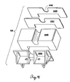
Applicant's have provided in the embodiment illustrated in these figures a means for attaching a launch system (500) to box (100) and, further for storing launch system (500), as through the use, for example, of telescoping tubes and folding legs, within the interior of the box.
Here, longitudinal members (212A) and (212B) engage channels (302) on the under side of the wings or attached to the fuselage, or other parts of the aircraft, which channels are dimensioned to slidably accept the longitudinal members so as to maintain the airborne vehicle on a straight course over the longitudinal members as it accelerates to flying speed.
While the engine of the aircraft may be energized to accelerate the aircraft to flying speed Applicant's launch system (500) may include a power assist means (514), here engaged to the box and including a gas propellant means such as the cartridge of a firearm, which may propel the aircraft through means including telescoping tubes (518) with aircraft engaging bracket (520) on the removed ends thereof. Note that gas propellant means (516) may include a trigger (522) for remotely activating a cartridge of other gas propellant means to drive the aircraft over the launch longitudinal members. Launch system (500) includes cross-bracket (510) to assist in bracing and maintaining the longitudinal members in their proper position. Stops (509) may help brace folding legs (502) adjacent the sidewalls of the box (100) (See FIG. 3D ). FIG. 3E illustrates the manner in which aircraft engaging brackets (520) may receive, in a slot thereof, the trailing edge portion of the lower wing. Any other suitable means may be provided for engaging the aircraft to the power assist means to propel the aircraft from a stationary position at a near end of the longitudinal members to flying speed as it reaches the removed end of launch system (500). FIG. 3E also illustrates that the attitude or angular relationship between the ground and a longitudinal axis of the launch rail may be adjusted by using legs (122) between a lower surface of the box (100) and the ground to raise the longitudinal members and the launch system. Furthermore, the box, and therefore the launch systems may be firmly anchored to the ground through of “L” brackets (116) and pegs (120) such that when the power assist means (514) is activated the box and the launch system will stay firmly implanted on the ground and the aircraft will move forward on the launch rail. It is noted that longitudinal members (512A) and (512B) may have either telescoping extensions or threaded attachments that can be threadably detached and stored in the box.
The empennage is seen to include a vertical stabilizer (322) having a rudder (324) thereon and horizontal stabilizer (326) having an elevator (328) thereon, the empennage to control pitch and yaw in a manner known in the prior art. Wings (308) are seen to include ailerons (308) for roll control in a manner known in the prior art. Ailerons may be coupled, with both the forewing and aftwing having aileron controlled surfaces or, in an alternate preferred embodiment, only the aftwing may have aileron control surfaces. In an alternate preferred embodiment, Applicant provide servo activated flaps. Note that the wings are positively staggered, with the upper wing being located forward of the lower wing.
A flight management system module (334) is included within the fuselage for management of flight systems as herein set forth. The aircraft may include a camera for visible spectrum or infra-red reception, and may also include a video transmitter such as C band video transmitter (335) located within the fuselage. FIGS. 5A and 5B also illustrate elevator and rudder servos (336) for controlling the elevator and rudder surfaces. A lightweight plastic 14 ounce fuel tank (337) is also provided within the fuselage. A parachute recovery system (338) also attaches in modular fashion to the interior and on surface portions of the fuselage. (See FIG. 5G ).
Applicants also provide a wing removal mechanism (339) that will allow the wings to be detached from the fuselage for placement adjacent to the fuselage within the box or container (100). The removal mechanism includes a wing alignment pin (340) for attaching the wing to the fuselage at the proper angle. Applicants forewing and aft wing are attached at the wing tips and include wing tip fastener (341) for removably attaching the endplates to the wing tips.
Applicants airborne vehicle is intended as a miniature aircraft to perform “recognition, intelligence, surveillance, and target acquisition” missions for taking video photographs in the infrared or visual spectrum of the ground surface over which it flies and transmitting the images on an analog signal back to a ground control station for visual display. As part of that system Applicants airborne vehicle (300) may include an infrared (or visual spectrum) sensor or camera (342) as seen in FIG. 5A rigidly attached to the fuselage of the aircraft and directed downward when the aircraft is in normal flight with its wings level and fuselage level to the horizon. In this fashion pre-programmed or remote control of the three axes of the aircraft will control the area of exposure on the ground to the camera and therefore to the military scout in attendance at a remotely located visual display. The flight management system allows the scout full three axis control of the aircraft so as to effectively direct the camera at the will of the operator. The flight management system may be pre-programmed or reprogrammed or real time controlled to focus on a fixed, selected ground target.
Turning now to FIG. 5C it is seen that fuselage (304) has a flat top with a top fuselage cutout (354) therein. Fuselage cutouts may be located in sidewalls or even the bottom of the fuselage. The cutout may be used to mount a cover therein for removal of elements carried within the walls of the fuselage such as elements of a flight management system, C-band video transmitter, fuel tank, electrical system and other components. Furthermore, at least a portion of a top fuselage cutout (354) may serve to store therein parachute recovery system (338) (See FIG. 5G ).
Note also with reference to FIGS. 5D and 5E that launch interface bracket (343) is incorporated into a tricycle landing gear (355) and contains a slot (343A) for slotting onto a launch rail or launch device as set forth in FIGS. 6A and 6B . Tricycle landing gear (355) includes main wheels (355A) and nose wheel (355B). With the use of wheels as part of a landing gear in addition to the slots of launcher interface bracket (343) as illustrated in FIGS. 5A and 5B , the operator of airborne vehicle (300) has the option of making a normal nonlauncher takeoff (runway) as well as a nonparachute return (typical runway landing). Further, it is seen that tricycle landing gear (355) has some resilience or “give” between the fuselage and the wheels through the use of an aluminum main gear and a spring (355C).
The nose wheel may be steerable, coupled to the rudder for improved ground handling during conventional ground handling, taxiing, take-off, and landing. Fuselage (304) may also includes cooling ducts (356) seen in FIG. 5D to be located in the sidewalls of the fuselage for cooling components within the fuselage. Note also with references to FIG. 5E that G.P.S. Unit (331) is externally mounted to the fuselage, but may be placed internal to the fuselage, and is removably attached with velcro or other means. FIG. 5F illustrates an additional view of airborne vehicle (300). This view illustrating a sensor (camera) bay (357) for placement of the camera, and, optionally, a globe, gimble and other elements of a pan and tilt system (349) therein. Also, illustrated in FIG. 5F is a C-Band transmitter (358) for transmitting signals to the ground control station and optionally a (signal receiving only) remote imaging system.
Applicants achieve a number of the design goals in the system set forth herein. The aircraft is lightweight and compact. This is achieved through the use of lightweight materials such as carbon fiber, aluminum, foam, and balsa wood used in the fuselage wings, engine, and other elements of the system. It is also lightweight and compact due to its staggered wing configuration with the wing length typically less than the length of the fuselage and with end plates providing additional structural integrity. With the staggered wing configuration, more surface area, and therefore greater carrying capacity can be achieved in an aircraft with a limited wing span.
Applicants' use of a generator on the aircraft engine allows for the generation of electrical power for onboard systems, eliminating the excess weight of additional batteries. The use of a gas/oil mixture instead of methanol to fuel the engine also reduces the weight of the aircraft by providing greater range per given mass of fuel.
The launcher is designed to easily assemble and breakdown and fit into a container, without the use of tools. Furthermore, it is rail launched using a propellant applied controllably to control the initial G-loading to the aircraft.
The aircraft achieves a high power to weight ratio, here for example illustrated with a 1.5 horsepower engine in an aircraft achieving a design weight of about 10 pounds with a full fuel load. The aircraft typically uses a cruise prop to achieve better gas consumption. The switch from methanol to gas also allows for a better fuel consumption rate.
With the understanding of these features of wing hinge assembly (362), it may be appreciated that if sleeve (362) is rigidly mounted partially within the fuselage and perpendicular thereto with some portion extending perpendicularly outward from the fuselage side walls (see FIG. 5D ) (339A) that the wing may be pulled out, when the wing is anchored to the removed portion of the rod and folded (FIG. 5J ) with the wing root still attached to the removed portion of the rod. In other words, fasteners, not shown, can normally maintain the wing in a flight ready configuration with a fastener going through the wing, through the sleeve and into the rod. This fastener would be for fastening the elements together when the wing is in the position of a straightened end (see FIG. 5I ). This fastener would be removable to allow the wing, still attached through a fastener located on the wing and through only the removed end of the rod, to be pulled out so that the pin rides along leg (362E) and then the wing could be rotated with the pin in foot (362F) and then folded on folding hinge (362G) to lay adjacent the fuselage for storage in the container.
Leg assembly (204) includes a pair of downwardly depending legs (206) and (208). The legs have a removed end for resting on a surface such as the ground, and a near end for pivotal attachment to a leg bracket (210), the bracket mounted to the underside of front section (202). This allows forward end (202C) to be raised with respect to a support surface, such as the ground and rearward end (203D) to rest against the ground.
Launch carriage (212) is designed to engage aircraft vehicle (300) to rail (201) in a slidable fashion such that propelling launch carriage (212) with airborne vehicle (300) thereon longitudinally along the upper surface of the rail will help propel aircraft vehicle (300) from a stand-still to launch speed before the carriage reaches forward end (202C) of front section (202).
Applicants include a cartridge chamber (220) having an elongated retractable spring loaded firing arm (222) engaged therewith. A lanyard (224) has a handle (226) at a removed end thereof, the lanyard having a near end (224A) where it is attached to a trigger (227) (See also FIG. 6D ).
In FIG. 6D , additional elements of Applicants' leg assembly (204) and cartridge chamber (220) may be seen. Leg bracket (210) is seen to include a U-shaped channel (210A) with uprights for engaging two sidewalls of front section (202) and a cross member between the two uprights for engaging the bottom of front section (202) in the manner set forth in FIG. 6D . A pair of ball lock pins or other quick release, tooless fasteners (210B) may be used to fasten the U-shape channel to the sidewalls of the rail. Threaded fastener (210C) engaging the upright portion of U-shape channel (210A) also engages the near end of the two leg such that the leg can pivot inwards towards one another on the shaft of the fastener. Strap (210D) limits the outward movement of the legs. Lengthening or shortening the strap will also allow the forward portion of the rail to be raised or lowered accordingly. Further, the removed ends may be adjustably extendable by having telescoping members for telescoping within legs (206) and (208) so as to effectively raise or lower the angle the rail makes with respect to the ground.
Turning to FIG. 6F , it is seen that rod (233) has attached to its removed end a set of movable pulleys to (234) which are engaged with steel cable (235) to a set of end mounted fixed pulleys (236). The fixed and movable pulleys comprise a block and tackle system (237) for multiplying the distance moved by rod (233) into a greater distance covered by cable tethered launch cartridge (212). That is, cable (235) has a fixed end anchored to the block carrying the movable pulleys and a second or removed end attached to the launch cartridge. Between the two ends the cable is wound around one or more pulleys of movable pulleys (234) and around an equal number of fixed pulleys at forward end (202C). Two movable and two fixed pulleys will multiply the distance the rod moves by 2, and three sets will multiply the distance the rod moves by 3, etc.
One end of cable (235) is attached to the movable pulley assembly and the other end of the cable engages the launch carriage. When the cartridge is fired, expanding gas forces the rod into the cylinder causing the movable pulley assembly to move and the carriage assembly to move a multiple of the distance moved by the rod. Therefore, Applicants' system not only propels the airborne vehicle but does so including a means to multiply the distance over which the force is applied. This tends to smooth out the application of the force generated by a cartridge (not shown) such as a 45 caliber cartridge (without the slug portion, of course) being fired by the activation of the trigger and release of the firing arm (222) from its extended spring loaded position (spring inside cartridge chamber (220)) for impacting a firing pin into the cartridge.
The sudden explosive charge and expansion of the gas resulting from this detonation may be diffused or slowed down by using a restrictor plate (228B) somewhere between the cartridge assembly and the cylinder. Restrictor plate (228B) with a small orifice (228C) is shown to be located and threadably received within the elbow such that it is sandwiched between the elbow and the cylinder when the elbow is threadably attached to fitting (230) (See FIG. 6D ). The function of restrictor plate (228B) is to slow down the application of the force to the carriage and prolong the application of the force to the carriage so as not to damage any parts of the assembly with excessive acceleration.
With the above description of the launcher it is seen that a number of novel features are provided and goals achieved. The launcher will “break down” and is dimensioned for fitting within the backpackable container. The breakdown may be accomplished without the use of tools. A propellant is provided to power the aircraft off the launch rail and the controlled application of the propellant is achieved so as not to overload any component of the assembly or the aircraft. Also, the rail may fold with respect to the container and be attached thereto (See FIGS. 3A–3F ) and the legs may fold in. This is designed to achieve a compact assembly. Moreover the power source, here a cartridge, is self-contained and delivery of the power to the launch carriage is modulated. The “tripod setup” of the launcher with the two legs forward and the rear portion of the rail against the ground is adjustable so as to setup with wings level and nose skyward even on an even ground, and may be used to vary the height of the front of the rail above the ground. A lanyard pull is provided to trigger the cartridge. Light weight is achieved through use of aluminum, titanium, carbon fiber, stainless steel and aluminum.
Applicants launcher has achieved means of controlling acceleration and also controlling deceleration so as to control the “g” loading on the elements of the launcher, including the load on the aircraft while under acceleration and deceleration. This achieves a balance in powered delivery. The length of the rail is necessarily limited by the dimensions of the container and the requirements for “backpackability” of the unit, yet power delivery must be sufficient to provide a launch velocity to the aircraft which will exceed the stall speed of the aircraft at a given density altitude. Moreover, Applicants have achieved, through a three point attachment of the aircraft to the carriage that is slotted, the ability for the aircraft to fly off the carriage under its own power as the carriage decelerates. The carriage will be undergoing negative acceleration (slowing) over, typically, the last 6 to 12 inches due the pair of pneumatic “air shocks” attached between the rails. This deceleration combined with the slotted system (slots open forward) will allow the aircraft to move forward under its own power at a velocity sufficient to maintain flight.
Turning now to FIG. 7B , note that when the aircraft is on the launch carriage (212), shear pins such as bamboo splints may be used, one or more (352B) to hold the plane on the carriage while the carriage is stationary and the plane is running, trying to move forward off the carriage, and the other one or more shear pins (352C) between the carriage and the rail to keep the carriage/plane combination from creeping up the rail before the launch cartridge is fired.
It is seen with reference to FIG. 5G that a carbon fiber shell (361I) is shaped for receipt within the cutout at the top of the fuselage of the aircraft (See FIG. 5C ) in that shell (361I) has a lip (361K) around an upper surface thereof that can engage the similarly shaped opening in the top of the fuselage such that the shell portion is inside the fuselage and the upper lip of the shell is adjacent the top surface of the fuselage. A similar lip (361L) on lid (361J) may rest against the upper surface of the fuselage or the upper lip of shell (361I) and a chute deployment servo activated arm (not shown) may overlap the lip of the lid when the aircraft is normally in flight. Preprogrammed or operator activated parachute recovery is initiated and the lid engaging arm moves out of interference with the lip (361L) of the lid. Stuffed (stowed) beneath the lid is the pilot chute. Release of the lid will allow air to get up underneath the leading edge of the lid and flip it off of the top of the fuselage, dumping the pilot chute into the airstream. The pilot chute will fill with air and deploy the main canopy, slowing the airborne vehicle in a descent to the ground.
Applicant's provide the following additional features and modifications of their novel airborne reconnaissance system. It has been noted that the rail member of the launch system may be broken down into two or more sections. Applicant's provide for a tongue and slot arrangement for detaching one rail section from the other (See FIG. 7G ) along with a pin, such as a ball lock pin for insertion through the aligned holes in the tongue and slot. Applicant also provides for sections that are permanently attached to adjacent sections by hinges so that they may be folded against one another for easy storage in the box (See FIG. 7F ). Further, the legs that Applicant's provide to support one end of the launcher may be either completely removable via the bracket illustrated in FIG. 6D , or may be hinged or pivoted on a bolt and permanently attached to one end of the rail but foldable so that the legs can fold against the rail for easy storage.
Applicant's describe herein a means for propelling the carriage assembly from one end of the launch rail to the other so as to propel the aircraft off the end of the launch rail at flying speed. One means for propulsion described herein includes a cartridge assembly. A second means of propulsion includes an elastic cord or cords for engaging, in a stretched position the carriage assembly at a first end of the rail and, when the carriage assembly is released, accelerating the carriage assembly as the elastic cord or cords contract, to the other end of the rail assembly to accelerate the aircraft on the carriage assembly to take off speed.
While Applicant's disclose an aircraft having a particular configuration, here a staggerwing biplane, in fact Applicant's system may utilize an aircraft of any wing or engine configuration: including, monoplane, tri-wing, canard, tractor, pusher, or any combination.
While Applicant's provide for, in the above described embodiment, a tricycle landing gear as part of the airborne vehicle, Applicant's also provide for a “tail dragger” configuration with resilient members depending from either fuselage or lower wings, the resilient depending members either having a pair of wheels attached for conventional landing or being wheelless (See 7H).
Note the manner in which the carriage assembly engages the legs and the boss on the tail assembly. Basically, slots or grooves that open forward allow the carriage assembly to accelerate the aircraft and as, the carriage decelerates at the end of its travel, allow the aircraft to fly forward out of the slots and away from the launch rail. Applicant's retainer means (for example, bamboo splints) may be incorporated into appropriate holes in the legs and/or bosses extending therefrom.
Applicant's also provide, in preferred embodiment of the unmanned airborne vehicle described hereinabove, a parachute descent for the airborne vehicle. That is, Applicant's provide for an unwheeled airborne vehicle which contains only means for engaging the carriage assembly to effect take off from the rail. Landing is accomplished through parachute descent, the parachute typically stowed within the fuselage and ejected therefrom by an ejection means such as a plate and a spring backing against the plate on one end and on the fuselage on the other (See FIGS. 5G ). Triggering the ejection/deployment means may be preprogrammed into the onboard computer for ejection at a given time, altitude, GPS position or emergency (engine failure, for example). The triggering of the ejection system of the parachute may also be provided by remote control operated, from a remote control station.
Thus, Applicant's provide a novel airborne recovery system for bringing an unmanned airborne vehicle back to earth, which system uses remote or preprogrammed triggering of a parachute ejection system as set forth in FIG. 5G . Applicant's also describe, in FIGS. 7I , 7J, 7K and 7L, a novel means for releasing the unmanned airborne vehicle from the parachute when the vehicle strikes the ground. This may be necessary when, for example, there is a strong wind and the vehicle is descending into rugged terrain, to avoid the vehicle being dragged, and perhaps damaged, by a windfilled parachute after the aircraft has struck the ground.
Applicant's automatic release system includes, as set forth in FIGS. 7I to 7L , an elongated hollow housing having a nose end and a removed end. The nose end is slotted and the housing is hollow, with the threaded end for receipt of a threaded retainer cap thereon. The housing also includes one or more guide pin slots. A plunger is dimensioned for receipt into the housing, the plunger having a sloped plunger head, a plunder shaft and a removed end. The plunger head is designed for sliding receipt into the interior of the housing. The plunger head contains an angled nose with a disarming pin insert in the face thereof. A hole for receipt of a guide pin therein is typically provided in the head. The head is seen to have a greater diameter then the shaft. A spring is provided for receiving onto the shaft of the plunger, the spring captured at one end by the shoulder between the head and shaft and the other end by the threaded retainer. The spring will urge the nose of the head of the plunger towards the nose of the housing (See FIG. 7J ). The removed end of the plunger has a cutout for receipt of a ring or other means to engage the suspension lines of the canopy of the parachute. An engagement arm is provided with a ball end and a loop end, the loop end for engagement with the fuselage of the aircraft. The ball end has a cutout or notch for receipt of one end of the disarming pin therein. The engagement arm is dimensioned to fit within the slot of the nose of the housing and, the ball being larger than the slot the ball, will be held against the interior of the nose by the pin when the parachute release device is “armed” as seen in FIG. 7J . A disarming pin will “arm” the device by separating from the plunger which is normally bias towards the nose of the housing. One end of the disarming pin is in the ball of the engagement arm and the other in the insert of the slanted face of the plunger, disarming the device.
Opening shock during deployment of the parachute from the aircraft will create tension in the device pulling the plunger away from the nose of the housing and allowing the disarming pin to fall out and “arm” the device. Following opening shock (and loss of the disarming pin, thus “arming” the device) the spring will cause the plunger nose to move toward the nose of the housing and kick out the disarming pin if the disarming pin has not fallen out, due to the slope on the face of the plunger. However, tension in the device due to the weight of the aircraft suspended beneath the canopy of the parachute will maintain engagement of the ball with the nose. However, the aircraft strikes the ground the parachute will continue to descent and the housing will descend with respect to the ball and the sloped nose of the plunger will kick the ball out causing disengagement between the engagement arm and the nose of the housing and separation of the parachute from the fuselage. The entire unit is typically made from machined aluminum so as to be lightweight but strong and durable.
The box or container for containing therein Applicant's broken down aircraft and launch rail is typically about 40 inches long, 16 inches wide and, 10 inches high. It typically weighs between 3 and 15 pounds and is made of one or more of following materials: fiberglass, aluminum, plastic, composite, carbon fiber, foam and metal. It is generally rectangular with lid and is substantially weatherproof and waterproof (including gaskets between the lid and the box). The walls of the box may also include an air pressure compensating valve to allow pressure relief when there is a pressure differential between the air inside the box and the air outside the box. The interior of the box may also include foam or a soft pliable material to place between and cushion elements contained therein.
The wings and/or tail of the aircraft may be detachable from the fuselage. By detachable Applicant's means they may be physically removable from the fuselage or may remain attached to the fuselage as by hinge, but may be foldable against the longitudinal axis of the fuselage. Detachment by removal may be accomplished by a rod and pin arrangement between the root of a wing section and the fuselage. Detachment by folding may be accomplished by a hinge mechanism as illustrated in FIGS. 5H and 5J . Both wing sections of the biplane may be either detached by a complete removal or both wing sections of the biplane may be detached by a hinge. As illustrated in FIG. 7D it is seen that one section may be removed and the other section hinged. Indeed, the empennage may include removal or detachment in the same manner of the horizontal stabilizer sections and/or the vertical stabilizer as seen in FIG. 7C .
Applicant's novel reconnaissance system includes a guidance system on the unmanned aircraft which includes a programmable computer means to control the flight path of the aircraft so as to reach a predetermined point removed from the launch site. The unmanned aircraft may also include a fixed or moving camera capable of receiving images beneath the flight of the unmanned aircraft. Onboard telemetry means may provide for real time signal transmission of images to a remote site, the remote site including, for example, a control station, a remote receiver and a display, for receipt and display of real time telemetry signals including images. The remote station may include a transmitter for transmitting signals to an onboard receiver which can overwrite any preprogrammed signals to the control surfaces allowing an individual at the remote site to “fly” by the remote display and the remote control system, the aircraft. Indeed, a remote operator can overwrite the preprogrammed flight to bring the aircraft back to or near the remote station and the remote operator can trigger the preprogrammed parachute for remote deployment upwind of the control station so that the aircraft via parachute deployment, can be returned to the operator even if the operator has moved between launching the aircraft and returning the aircraft.
An elongated rail member 602 is provided for the support of a carriage thereon, the carriage for engaging the airborne vehicle 300. Rail member 602 includes a front end 602A and a rear end 602B, the front end typically elevated, as for example on adjustable length legs 630 foldably attached to the rail member. A power system for launching an airborne vehicle may include an elastic cord 600, the cord for example being made of surgical tubing such as that sold under the trademark K911 by Kent Elastoner Products, Inc. The elastic cord may have a first end 600A and a second end 600B. “C” channel 604 is provided on both sides of the rail member to guide a carriage 606 from one end of the rail member to the other. The carriage 606 may include a multiplicity of legs 606A, the legs, at their removed end having pivotally mounted thereto wheels 606B (see FIG. 11 ), the wheels adapted to fit inside the “C” channel 604. The carriage may also include a base 606C. The base 606C may include fuselage engagement and support member 606D which will engage the fuselage and help support the fuselage of the aircraft. Fuselage engagement and support member 606D may include slots 606E for engaging bosses 608. Bosses 608 are mounted on the fuselage and slots 606E open to the front of the carriage. Therefore, when the carriage accelerates the aircraft from right to left as seen in FIG. 8 , the aircraft can fly off the fuselage engagement and support member 606D and become airborne. The carriage may also include a forked hook 606F or other device for engaging reel cable 616 in a manner set forth below. Therefore, structure is provided for locating the airborne vehicle in a stable non-flying position and accelerating it on the carriage structure from one end of the rail to the other where it can “fly off” the device. Note that the airborne vehicle in this embodiment does not have a landing gear and the carriage engages a fuselage directly.
A reel system 610 is provided to energize the carriage by engaging the carriage, through a cable to the elastic cord. The reel system 610 moves the carriage to the removed or rear end 602B of the rail member, a position which stretches the elastic with respect to the carriage. This loads the system for subsequent release of the carriage and acceleration of the airborne vehicle from the right end to the left end of the rail as seen in FIG. 8 . The reel system provides a carriage cable 622 for engagement at a first end 622A to the rear end of the carriage and for engagement at a second end 622B to a rotatable spool 612. The reel system provides a crank handle assembly 614 which when rotated will cause the spool to rotate and take up the carriage cable 622 thereby moving the carriage from the left to right as seen in FIG. 8 until the rear end of the carriage assembly is adjacent a trigger assembly 626, which trigger assembly will releasably engage the carriage. The function of reel system 610 is to provide a mechanical advantage, here through a set of gears and a spool, to dissipate the force required in stretching the elastic cord. As in the earlier embodiment featured above, the present embodiment provides a system for propelling the airborne vehicle from one end of the launch rail to the other, typically with sufficient energy to reach the takeoff velocity for the vehicle. In an earlier embodiment, the energy was provided by chemical potential energy in an explosive charge providing a sudden expansion of gas. In the embodiment featured in FIGS. 8–14 , an elastic cord 600 is provided and elastic potential energy is stored as the cord is stretched, which elastic potential energy is converted to kinetic energy when the trigger is released and the carriage borne vehicle is accelerated from one end of the launch rail to the other.
A means for providing engagement between elastic cord 600 and the carriage is disclosed herein. More specifically, a rigid elastic mount plate 616 is provided at or near the rear end of the launch rail (see FIG. 11A ). Typically, the elastic cord comprises a multiplicity of elastic bands or tubular members that are mounted at one end thereof to the rigid plate. The other end of the multiplicity of elastic bands are mounted to a moveable elastic mount plate 620 which is dimensioned to fit slidably within the hollow interior of the rail member 602.
A fixed pulley 624 is provided at the first end of the rail member. Fixed pulley 624 provided for engaging carriage cable 622. As seen in FIG. 8 , carriage cable 622 has a first end attached to the carriage and, extending forward from the carriage, the carriage cable will engage the fixed pulley to loop around so the carriage cable can enter the interior of the rail member and engage the moving plate. With the carriage engaged with trigger assembly 626 and elastic cord 600 stretched, release of the trigger assembly will allow the carriage to slide forward and accelerate towards the first end of the rail. Applicants provide a carriage stop block 628 to engage the carriage so the carriage does not fly off the end of the rail, the sudden stop of the carriage allowing, however, the airborne vehicle 300 to fly off the carriage as the carriage stop block assembly 628 is designed only to engage the carriage and not the airborne vehicle.
Turning now to details set forth in FIG. 9B , it may be appreciated that hinge 636 may allow the first and second section of the rail members to join in flush engagement. Further, one of the two sections and the other of the two sections may be configured to define an alignment tongue and groove couple 642 as illustrated to help center and guide the two sections of the rail member as they come together as illustrated in FIG. 9B . Applicants further illustrate, in FIG. 9B , a locking plate 638, the locking plate including a portion for engaging first section 632 and a portion for engaging second section 634 in such a way as to pull the two sections flush against one another with a longitudinal axis thereof in alignment such that the C channels of each section meet flush to one another. Thus, the carriage may pass over the joint between the two sections without interference. The way in which this function is achieved are in providing the locking plate 638 with tongues 638A and 638B for engaging grooves 640A and 640B, a groove in each of the two sections, and locking plate 638 for sliding on from the side of the rail. Having a low profile, avoids interference with the passage of the carriage. It is noted that while two sections of the rail member are illustrated, the rail member to be broken down into additional sections and may be pivoted or engaged as by tongue and groove or other means illustrated in these specifications.
Turning now to FIG. 12 , it is seen that a carriage block assembly 628 is provided to absorb the energy of the carriage as it approaches the end of the rail member. A suitable carriage block assembly has been provided, here comprising a mounting bracket 628A for mounting a foam block 628B to the carriage rail. A metal plate 628C (typically aluminum) may be provided upon which a rubber pad 628D may be applied, the metal plate and rubber pad then applied to a forward portion of the foam block. In this manner, the carriage will strike the rubber pad rather than the metal of the plate, but the plate will provide for a uniform transfer of the kinetic energy of the carriage into the foam block which will undergo elastic deformation. Since the foam block is installed at the front of the rail, a cable groove 628E is usually provided in all elements of the carriage stop block assembly 628 to avoid interference with the cable.
Turning now to FIG. 13 , details of Applicants' elastic cord 600 are provided. It is seen that carriage cable 622 at a first end 622A may include a ball 666 and a retainer nut 668 which may engage a retainer bolt 668A, the bolt mounted to plate 620 to hold the carriage cable to the mounting plate. A first set of tubing retainer bolts 670 may be provided for engagement with a multiplicity of elastic bands and may be, indeed, molded therewith. A second set of tubing retainer bolts 672 may be provided, again molded with the removed end of individual cords, which may engage threaded fixed mounting plate 618. Thus, elastic cord may be seen to comprise one or more individual bands, for example five illustrated in FIG. 13 . One end of the individual band is mounted to the fixed mounting plate, the other to the moveable mounting plate. A pattern of five (or any suitable number) may be provided for providing equal pressure to the moveable mounting plate, here the five individual bands are seen to be mounted equally distant from the center of the moveable mounting plate near the four corners of the rectangular plate and one at the center. Such uniform and symmetrical mounting would tend to hold the moveable mounting plate perpendicular to the housing. Note the head of retainer bolt 668A engages the end of the center located elastic end.
Although the invention has been described with reference to specific embodiments, this description is not meant to be construed in a limited sense. Various modifications and/or enhancements of the disclosed embodiments, as well as alternative embodiments of the inventions will become apparent to persons skilled in the art upon the reference to the description of the invention. It is, therefore, contemplated that the appended claims will cover such modifications that fall within the scope of the invention.
Claims (2)
1. An airborne reconnaissance system comprising:
an airborne vehicle having a fuselage and wings defining a biplane, the wings adapted to be removed from the fuselage, the airborne vehicle including an onboard video camera and video signal transmitter and a flight control system to remotely control a flight of the airborne vehicle from a remote location;
a launch system including a launch rail having a longitudinal axis comprised of at least two sections;
power means;
a carriage for slidable receipt onto the launch rail member for engagement with the airborne vehicle and for engagement to the power means to power the carriage along the rail; and
a container adapted to receive thereinto the airborne vehicle with the wings removed from the fuselage and the launch rail thereof.
2. An airborne reconnaissance system comprising:
an airborne vehicle having a fuselage and wings defining a biplane, the wings adapted to be removed from the fuselage, the airborne vehicle including an onboard video camera and video signal transmitter and a flight control system to remotely control a flight of the airborne vehicle from a remote location;
a launch system, including a launch rail having a longitudinal axis and comprised of at least two separate but engageable sections;
a carriage for slideable receipt onto the launch rail for engagement to the airborne vehicle;
means to power the carriage along the launch rail member; and
a backpack adapted to receive the airborne vehicle with the wings removed from the fuselage and, the at least two launch rail sections.
Priority Applications (2)
| Application Number | Priority Date | Filing Date | Title |
|---|---|---|---|
| US10/625,399 US7210654B1 (en) | 2003-07-23 | 2003-07-23 | Unmanned airborne reconnaissance system |
| US11/030,379 US20060102798A1 (en) | 2001-05-21 | 2005-01-06 | Unmanned biplane for airborne reconnaissance and surveillance having staggered and gapped wings |
Applications Claiming Priority (1)
| Application Number | Priority Date | Filing Date | Title |
|---|---|---|---|
| US10/625,399 US7210654B1 (en) | 2003-07-23 | 2003-07-23 | Unmanned airborne reconnaissance system |
Related Parent Applications (1)
| Application Number | Title | Priority Date | Filing Date |
|---|---|---|---|
| US10/143,603 Continuation US6626398B1 (en) | 2001-05-10 | 2002-05-10 | Unmanned biplane for airborne reconnaissance and surveillance having staggered and gapped wings |
Related Child Applications (1)
| Application Number | Title | Priority Date | Filing Date |
|---|---|---|---|
| US11/030,379 Continuation-In-Part US20060102798A1 (en) | 2001-05-21 | 2005-01-06 | Unmanned biplane for airborne reconnaissance and surveillance having staggered and gapped wings |
Publications (1)
| Publication Number | Publication Date |
|---|---|
| US7210654B1 true US7210654B1 (en) | 2007-05-01 |
Family
ID=37991342
Family Applications (1)
| Application Number | Title | Priority Date | Filing Date |
|---|---|---|---|
| US10/625,399 Expired - Lifetime US7210654B1 (en) | 2001-05-21 | 2003-07-23 | Unmanned airborne reconnaissance system |
Country Status (1)
| Country | Link |
|---|---|
| US (1) | US7210654B1 (en) |
Cited By (101)
| Publication number | Priority date | Publication date | Assignee | Title |
|---|---|---|---|---|
| US20060186266A1 (en) * | 2005-02-24 | 2006-08-24 | Avicade Industry Pty Ltd | Multipurpose model-aircraft launching apparatus |
| US20080087764A1 (en) * | 2003-10-20 | 2008-04-17 | Central Japan Railway Compay | Flying vehicle-launching apparatus and method |
| US20090105892A1 (en) * | 2007-10-19 | 2009-04-23 | Draughon Ryan J | Telemetry analysis system networked data acquisition system |
| US20090314882A1 (en) * | 2006-07-25 | 2009-12-24 | Goossen Emray R | Micro air-vehicle transport container and launch system |
| US20090314883A1 (en) * | 2007-05-10 | 2009-12-24 | Arlton Paul E | Uav launch and recovery system |
| US20100051755A1 (en) * | 2008-08-26 | 2010-03-04 | DarkStar LLC | Tail-less boxed biplane air vehicle |
| US20100051741A1 (en) * | 2008-09-03 | 2010-03-04 | Anvar Ismailov | Unmanned air vehicle |
| WO2010031384A2 (en) * | 2008-09-17 | 2010-03-25 | Gabler Maschinenbau Gmbh | Method for launching a drone |
| US20100096496A1 (en) * | 2008-10-20 | 2010-04-22 | Aai Corporation | Sliding frame aircraft launcher and related method |
| WO2011002331A1 (en) * | 2009-07-02 | 2011-01-06 | Открытое Акционерное Общество "Научно-Производственная Корпорация "Иркут" | Small unmanned aircraft system |
| US20110017863A1 (en) * | 2007-10-29 | 2011-01-27 | Honeywell International Inc. | Guided delivery of small munitions from an unmanned aerial vehicle |
| US20110062281A1 (en) * | 2008-05-13 | 2011-03-17 | Bae Systems Plc | Launch system |
| US20110168838A1 (en) * | 2009-04-27 | 2011-07-14 | Irvine Sensors Corporation | Launch tube deployable surveillance and reconnaissance system |
| US20110204180A1 (en) * | 2008-05-09 | 2011-08-25 | Jan Binnebesel | Ground-based apparatuts for take off, landing and taxiing of aircraft |
| WO2012006158A1 (en) * | 2010-06-29 | 2012-01-12 | Aerovironment, Inc. | Uav payload module camera assembly and retraction mechanism |
| US20120080556A1 (en) * | 2010-10-05 | 2012-04-05 | Lockheed Martin Corporation | Systems and Methods for Autonomous Operations of Unmanned Aerial Vehicles |
| US20120115391A1 (en) * | 2010-11-08 | 2012-05-10 | Sweet Spot Studio, Inc. | Toy projectile and launcher |
| US8220737B2 (en) | 2008-06-06 | 2012-07-17 | Frontline Aerospace, Inc. | VTOL aerial vehicle |
| CN101758921B (en) * | 2008-12-25 | 2013-04-17 | 西北工业大学 | Aerodynamic configuration for row-type flying wing high-altitude airship |
| US8439301B1 (en) | 2011-07-18 | 2013-05-14 | Systems Engineering Associates Corporation | Systems and methods for deployment and operation of unmanned aerial vehicles |
| US8511607B2 (en) | 2010-07-14 | 2013-08-20 | Arcturus UAV LLC | UAV launch attachment assembly and launch system |
| WO2014058511A2 (en) * | 2012-08-01 | 2014-04-17 | Bye Uas, Inc. | Small uas with high definition video |
| US20140117153A1 (en) * | 2012-10-26 | 2014-05-01 | The Boeing Company | Systems and methods to launch aircraft |
| CN103910070A (en) * | 2013-01-09 | 2014-07-09 | 碳基科技股份有限公司 | Folding-type ejector rack |
| CN104015933A (en) * | 2014-06-11 | 2014-09-03 | 毕和军 | Folded launching and withdrawing device for unmanned aerial vehicle |
| US20140263851A1 (en) * | 2013-03-14 | 2014-09-18 | Liquid Robotics, Inc. | Water Vehicles |
| CN104071347A (en) * | 2014-06-30 | 2014-10-01 | 中国人民解放军国防科学技术大学 | Folding unmanned aerial vehicle launch frame based on ejection of rubber band |
| US8855846B2 (en) * | 2005-10-20 | 2014-10-07 | Jason W. Grzywna | System and method for onboard vision processing |
| JP2015504814A (en) * | 2012-04-19 | 2015-02-16 | ウィンテック アローメイカー,インコーポレイテッド | Portable multimode unmanned aerial system launcher |
| US20150053819A1 (en) * | 2013-08-23 | 2015-02-26 | Becklin Holdings, Inc. | Fuselage indexing system and method |
| US20150063965A1 (en) * | 2013-08-27 | 2015-03-05 | The Boeing Company | Mechanism for translation/rotation in x-y directions |
| US20150060600A1 (en) * | 2013-08-27 | 2015-03-05 | Engineered Arresting Systems Corporation | Electric unmanned aerial vehicle launcher |
| CN104554814A (en) * | 2014-12-24 | 2015-04-29 | 南京航空航天大学 | Quickly and integrally folding type rubber band ejector |
| CN104803006A (en) * | 2015-04-27 | 2015-07-29 | 西北工业大学 | UAV (Unmanned Aerial Vehicle) catapult-assisted take-off device |
| US9127908B2 (en) | 2009-02-02 | 2015-09-08 | Aero Vironment, Inc. | Multimode unmanned aerial vehicle |
| US20150344135A1 (en) * | 2014-06-02 | 2015-12-03 | Sikorsky Aircraft Corporation | Aircraft with integrated single sensor |
| CN105137837A (en) * | 2015-08-12 | 2015-12-09 | 北京韦加航通科技有限责任公司 | Electric control system for launcher |
| CN105711851A (en) * | 2016-01-25 | 2016-06-29 | 中国人民解放军国防科学技术大学 | Electric and light-weight catapult with multiple strands of rubber strings for small unmanned aerial vehicle |
| CN106081150A (en) * | 2016-08-04 | 2016-11-09 | 湖南航天机电设备与特种材料研究所 | One launches supporting mechanism and ejection system thereof |
| US9561871B2 (en) | 2014-05-07 | 2017-02-07 | Deere & Company | UAV docking system and method |
| CN106542111A (en) * | 2016-11-02 | 2017-03-29 | 南京航空航天大学 | It is applied to the unmanned plane fixing device of unmanned plane transmitting |
| US20170158352A1 (en) * | 2013-04-02 | 2017-06-08 | Hood Technology Corporation | Multicopter-assisted system and method for launching and retrieving a fixed-wing aircraft |
| US20170313442A1 (en) * | 2016-05-02 | 2017-11-02 | Circor Aerospace, Inc. | Aerial vehicle launcher |
| US9908638B1 (en) * | 2016-05-27 | 2018-03-06 | Kitty Hawk Corporation | Impact velocity reduction by mass ejection |
| US9969504B1 (en) * | 2015-09-08 | 2018-05-15 | The United States Of America, As Represented By The Secretary Of The Navy | Automated multi-plane propulsion system |
| CN108082522A (en) * | 2017-12-19 | 2018-05-29 | 四川宝天智控系统有限公司 | Unmanned plane emitter and method |
| US10118713B2 (en) | 2013-08-27 | 2018-11-06 | Engineered Arresting Systems Corporation | Electric unmanned aerial vehicle launcher |
| US10155584B2 (en) | 2012-11-15 | 2018-12-18 | SZ DJI Technology Co., Ltd. | Unmanned aerial vehicle and operations thereof |
| US20180369672A1 (en) * | 2017-06-22 | 2018-12-27 | Spinway Technologies, LLC | Bowling Ball Launcher |
| USD843266S1 (en) | 2016-01-26 | 2019-03-19 | SZ DJI Technology Co., Ltd. | Aerial vehicle |
| US10249200B1 (en) * | 2016-07-22 | 2019-04-02 | Amazon Technologies, Inc. | Deployable delivery guidance |
| US10370120B1 (en) * | 2017-04-13 | 2019-08-06 | The Government Of The United States Of America As Represented By The Secretary Of The Navy | Launcher for an unmanned aircraft and methods of use thereof |
| US10377482B2 (en) * | 2015-05-01 | 2019-08-13 | Transition Robotics, Inc. | Remotely controlled modular VTOL aircraft and re-configurable system using same |
| US10501193B2 (en) | 2016-07-01 | 2019-12-10 | Textron Innovations Inc. | Aircraft having a versatile propulsion system |
| US10507914B2 (en) | 2013-03-15 | 2019-12-17 | Flir Detection, Inc. | Spooler for unmanned aerial vehicle system |
| CN110733661A (en) * | 2019-10-25 | 2020-01-31 | 苏州华瑞测绘有限公司 | unmanned aerial vehicle for aerial surveying and mapping and use method thereof |
| US10583921B1 (en) | 2016-07-01 | 2020-03-10 | Textron Innovations Inc. | Aircraft generating thrust in multiple directions |
| WO2020052612A1 (en) * | 2018-09-14 | 2020-03-19 | 青岛启航弹射科技有限公司 | Launcher catapult track device |
| US10597164B2 (en) | 2016-07-01 | 2020-03-24 | Textron Innovations Inc. | Aircraft having redundant directional control |
| US10604249B2 (en) | 2016-07-01 | 2020-03-31 | Textron Innovations Inc. | Man portable aircraft system for rapid in-situ assembly |
| US10618647B2 (en) | 2016-07-01 | 2020-04-14 | Textron Innovations Inc. | Mission configurable aircraft having VTOL and biplane orientations |
| US10618646B2 (en) | 2017-05-26 | 2020-04-14 | Textron Innovations Inc. | Rotor assembly having a ball joint for thrust vectoring capabilities |
| EP3636546A1 (en) * | 2018-10-08 | 2020-04-15 | Bell Helicopter Textron Inc. | Man portable aircraft system for rapid in-situ assembly |
| US10625853B2 (en) | 2016-07-01 | 2020-04-21 | Textron Innovations Inc. | Automated configuration of mission specific aircraft |
| US10633088B2 (en) | 2016-07-01 | 2020-04-28 | Textron Innovations Inc. | Aerial imaging aircraft having attitude stability during translation |
| US10633087B2 (en) | 2016-07-01 | 2020-04-28 | Textron Innovations Inc. | Aircraft having hover stability in inclined flight attitudes |
| US10661892B2 (en) | 2017-05-26 | 2020-05-26 | Textron Innovations Inc. | Aircraft having omnidirectional ground maneuver capabilities |
| CN111252264A (en) * | 2019-12-10 | 2020-06-09 | 中船重工海空智能装备有限公司 | Unmanned aerial vehicle emitter |
| US10703506B2 (en) | 2009-09-09 | 2020-07-07 | Aerovironment, Inc. | Systems and devices for remotely operated unmanned aerial vehicle report-suppressing launcher with portable RF transparent launch tube |
| US10710715B2 (en) * | 2015-07-01 | 2020-07-14 | W.Morrison Consulting Group, Inc. | Unmanned supply delivery aircraft |
| US10737778B2 (en) | 2016-07-01 | 2020-08-11 | Textron Innovations Inc. | Two-axis gimbal mounted propulsion systems for aircraft |
| US10737765B2 (en) | 2016-07-01 | 2020-08-11 | Textron Innovations Inc. | Aircraft having single-axis gimbal mounted propulsion systems |
| CN111634437A (en) * | 2020-06-08 | 2020-09-08 | 海丰通航科技有限公司 | Connecting structure of unmanned aerial vehicle ejection system |
| US10798272B2 (en) * | 2015-11-23 | 2020-10-06 | Hanwha Defense Co., Ltd. | Artillery shell-shaped information gathering device |
| US10870487B2 (en) | 2016-07-01 | 2020-12-22 | Bell Textron Inc. | Logistics support aircraft having a minimal drag configuration |
| US10894601B2 (en) * | 2017-12-20 | 2021-01-19 | Wing Aviation Llc | Methods and systems for self-deployment of operational infrastructure by an unmanned aerial vehicle (UAV) |
| US10899472B2 (en) | 2017-08-11 | 2021-01-26 | Ford Global Technologies, Llc | Vehicle mounted launcher for fixed-wing unmanned aerial vehicle |
| US10899441B1 (en) | 2013-04-02 | 2021-01-26 | Hood Technology Corporation | Multicopter-assisted system and method for launching and retrieving a fixed-wing aircraft |
| US10981661B2 (en) | 2016-07-01 | 2021-04-20 | Textron Innovations Inc. | Aircraft having multiple independent yaw authority mechanisms |
| US20210141160A1 (en) * | 2010-11-23 | 2021-05-13 | Stone Aerospace, Inc. | Method of Recovery of Optical Fiber Expended During Launch of a Spacecraft into Low Earth Orbit using a Non-Line-of-Sight Optical Power Transfer System |
| US11027837B2 (en) | 2016-07-01 | 2021-06-08 | Textron Innovations Inc. | Aircraft having thrust to weight dependent transitions |
| CN113120251A (en) * | 2021-05-24 | 2021-07-16 | 中国人民解放军国防科技大学 | Air-jet unmanned aerial vehicle launching tube |
| US11084579B2 (en) | 2016-07-01 | 2021-08-10 | Textron Innovations Inc. | Convertible biplane aircraft for capturing drones |
| US20210253242A1 (en) * | 2018-06-07 | 2021-08-19 | FLIR Unmanned Aerial Systems AS | Device for storing and remotely launching unmanned aerial vehicles |
| US11104446B2 (en) | 2016-07-01 | 2021-08-31 | Textron Innovations Inc. | Line replaceable propulsion assemblies for aircraft |
| US11124289B2 (en) | 2016-07-01 | 2021-09-21 | Textron Innovations Inc. | Prioritizing use of flight attitude controls of aircraft |
| US11142311B2 (en) | 2016-07-01 | 2021-10-12 | Textron Innovations Inc. | VTOL aircraft for external load operations |
| US11235892B2 (en) | 2019-05-22 | 2022-02-01 | Hood Technology Corporation | Aircraft retrieval system and method |
| US11267555B2 (en) * | 2018-01-08 | 2022-03-08 | GEOSAT Aerospace & Technology | Methods and unmanned aerial vehicles for longer duration flights |
| US11312491B2 (en) | 2019-10-23 | 2022-04-26 | Textron Innovations Inc. | Convertible biplane aircraft for autonomous cargo delivery |
| US11319064B1 (en) | 2020-11-04 | 2022-05-03 | Textron Innovations Inc. | Autonomous payload deployment aircraft |
| US20220234755A1 (en) * | 2019-06-18 | 2022-07-28 | Dae | Assembly comprising a launch motor vehicle and a jet-powered drone aircraft, and method for transporting and releasing a load |
| US11459099B2 (en) | 2017-05-26 | 2022-10-04 | Textron Innovations Inc. | M-wing aircraft having VTOL and biplane orientations |
| US11505302B2 (en) | 2017-05-26 | 2022-11-22 | Textron Innovations Inc. | Rotor assembly having collective pitch control |
| US11530035B2 (en) | 2020-08-27 | 2022-12-20 | Textron Innovations Inc. | VTOL aircraft having multiple wing planforms |
| US11608173B2 (en) | 2016-07-01 | 2023-03-21 | Textron Innovations Inc. | Aerial delivery systems using unmanned aircraft |
| US11630467B2 (en) | 2020-12-23 | 2023-04-18 | Textron Innovations Inc. | VTOL aircraft having multifocal landing sensors |
| US11628952B1 (en) * | 2022-02-10 | 2023-04-18 | Censys Technologies Corporation | Constant torque UAV device, method and system |
| US11643207B1 (en) | 2021-12-07 | 2023-05-09 | Textron Innovations Inc. | Aircraft for transporting and deploying UAVs |
| US11673662B1 (en) | 2022-01-05 | 2023-06-13 | Textron Innovations Inc. | Telescoping tail assemblies for use on aircraft |
| US11932387B2 (en) | 2021-12-02 | 2024-03-19 | Textron Innovations Inc. | Adaptive transition systems for VTOL aircraft |
Citations (51)
| Publication number | Priority date | Publication date | Assignee | Title |
|---|---|---|---|---|
| US922710A (en) | 1908-08-20 | 1909-05-25 | James Means | Apparatus for launching flying-machines. |
| US1353663A (en) | 1920-02-06 | 1920-09-21 | Charles H Napier | Target-throwing device |
| US1388361A (en) | 1920-05-06 | 1921-08-23 | Whitworth & Co | Airplane-launching apparatus |
| US1749357A (en) | 1928-08-02 | 1930-03-04 | Ernst M Schmelz | Aircraft-launching apparatus |
| US1749769A (en) | 1927-03-31 | 1930-03-11 | Fairchild Airplane Mfg Corp | Airplane-wing connection |
| US1960264A (en) | 1931-10-11 | 1934-05-29 | Heinkel Ernst | Catapult for launching aeroplanes |
| US2843342A (en) * | 1955-09-23 | 1958-07-15 | Task Corp | Mobile hydraulic catapulting apparatus |
| US2856139A (en) | 1956-04-05 | 1958-10-14 | Albert W Hainlin | Aircraft launcher |
| US2860620A (en) | 1956-02-15 | 1958-11-18 | Jr William L Effinger | Catapult for model aircraft |
| US2921574A (en) | 1957-03-29 | 1960-01-19 | Saito Hachio | Pitching machines |
| US3068612A (en) | 1961-10-23 | 1962-12-18 | Roba R Simpson | Self-controlled toy airplane |
| US3138352A (en) | 1962-08-16 | 1964-06-23 | Ryan Aeronautical Co | Launching system for pusher type propeller driven drones |
| US3392937A (en) | 1966-11-02 | 1968-07-16 | Bliss E W Co | Catapult system and method of launching vehicles |
| US3534929A (en) | 1969-02-20 | 1970-10-20 | Gulf & Western Ind Prod Co | Aircraft launching device |
| US3703998A (en) | 1970-12-28 | 1972-11-28 | Teledyne Ryan Aeronautical Co | Drone aircraft with telescopic fuselage |
| US3778007A (en) | 1972-05-08 | 1973-12-11 | Us Navy | Rod television-guided drone to perform reconnaissance and ordnance delivery |
| US3905350A (en) | 1973-08-27 | 1975-09-16 | Joseph T Becker | Launcher for toy vehicle having variable force means |
| US3968947A (en) | 1975-01-14 | 1976-07-13 | All American Industries, Inc. | Launching apparatus for flying device |
| US3985317A (en) | 1975-01-31 | 1976-10-12 | Alexander Geraci | Short coupled airplane with variable wing lift |
| US4014246A (en) | 1975-07-02 | 1977-03-29 | All American Industries, Inc. | Rocket-powered apparatus for launching a flying device |
| US4053125A (en) | 1973-08-30 | 1977-10-11 | Alexander Ratony | Staggered channel wing-type aircraft |
| US4060930A (en) | 1976-09-29 | 1977-12-06 | Mattel, Inc. | Toy airplane launcher |
| US4079901A (en) | 1976-04-07 | 1978-03-21 | All American Industries, Inc. | Launching apparatus for flying device |
| US4238093A (en) * | 1978-12-21 | 1980-12-09 | The United States Of America As Represented By The Secretary Of The Navy | Aircraft launcher |
| US4279195A (en) | 1978-12-22 | 1981-07-21 | Fairchild Industries, Inc. | Collapsible launching system |
| US4333382A (en) | 1979-12-26 | 1982-06-08 | The United States Of America As Represented By The Secretary Of The Navy | Boost assisted missile launcher |
| US4471923A (en) * | 1981-08-22 | 1984-09-18 | Vereinigte Flugtechnische Werke Mbb | Unmanned aircraft |
| US4530476A (en) * | 1981-08-12 | 1985-07-23 | E-Systems, Inc. | Ordnance delivery system and method including remotely piloted or programmable aircraft with yaw-to-turn guidance system |
| US4591114A (en) | 1985-02-07 | 1986-05-27 | Alvin Block | Automatic interlock connector arrangement for radio-controlled model airplanes |
| US4666105A (en) * | 1984-10-10 | 1987-05-19 | Messerschmitt-Boelkow-Blohm Gmbh | Unmanned aircraft |
| US4678143A (en) | 1982-12-17 | 1987-07-07 | Frazer-Nash Ltd. | Launcher for remotely piloted aircraft |
| US4856736A (en) | 1987-06-26 | 1989-08-15 | Skywardens Limited | Aircraft with paired aerofoils |
| US4909458A (en) | 1987-12-10 | 1990-03-20 | Schweizerische Eidgenossenschaft vertreten durch das Eidgenossische Flugzeugwerk | Device for the acceleration of bodies, especially a mobile catapult for flying bodies |
| US5035382A (en) * | 1989-04-17 | 1991-07-30 | Aerovironment, Inc. | Rapid assembly aircraft for ground surveillance |
| US5046684A (en) | 1989-02-09 | 1991-09-10 | Julian Wolkovitch | Airplane with braced wings and pivoting propulsion devices |
| US5118052A (en) * | 1987-11-02 | 1992-06-02 | Albert Alvarez Calderon F | Variable geometry RPV |
| US5303695A (en) | 1992-11-09 | 1994-04-19 | Noah Shopsowitz | Human free-flight launcher |
| US5575438A (en) | 1994-05-09 | 1996-11-19 | United Technologies Corporation | Unmanned VTOL ground surveillance vehicle |
| US5615846A (en) | 1994-11-04 | 1997-04-01 | Gec Marconi Dynamics Inc. | Extendable wing for guided missles and munitions |
| US5671722A (en) | 1996-05-29 | 1997-09-30 | The United States Of America As Represented By The Secretary Of The Navy | Projectile launcher |
| US5695153A (en) | 1995-11-16 | 1997-12-09 | Northrop Grumman Corporation | Launcher system for an unmanned aerial vehicle |
| US5779190A (en) | 1995-11-22 | 1998-07-14 | Northrop Grumman Corporation | Portable unmanned aerial vehicle |
| US5899410A (en) | 1996-12-13 | 1999-05-04 | Mcdonnell Douglas Corporation | Aerodynamic body having coplanar joined wings |
| US6056237A (en) * | 1997-06-25 | 2000-05-02 | Woodland; Richard L. K. | Sonotube compatible unmanned aerial vehicle and system |
| US6098923A (en) | 1998-03-13 | 2000-08-08 | Lockheed Martin Corporation | Aircraft structure to improve directional stability |
| US6119976A (en) * | 1997-01-31 | 2000-09-19 | Rogers; Michael E. | Shoulder launched unmanned reconnaissance system |
| US6144899A (en) | 1999-10-04 | 2000-11-07 | University Corporation For Atmospheric Research | Recoverable airborne instrument platform |
| US6186211B1 (en) | 1999-02-22 | 2001-02-13 | Aerospace Technologies Group, Inc. | Window assembly with a motorized window shade mechanism |
| US6576880B2 (en) | 2000-10-12 | 2003-06-10 | The Charles Stark Draper Laboratory, Inc. | Flyer assembly |
| US6626399B2 (en) * | 2001-12-26 | 2003-09-30 | Lockheed Martin Corporation | Miniature aircraft catapult |
| US20030192985A1 (en) * | 2002-04-10 | 2003-10-16 | Jay Lipeles | Stealthy duffel bag airplane |
-
2003
- 2003-07-23 US US10/625,399 patent/US7210654B1/en not_active Expired - Lifetime
Patent Citations (51)
| Publication number | Priority date | Publication date | Assignee | Title |
|---|---|---|---|---|
| US922710A (en) | 1908-08-20 | 1909-05-25 | James Means | Apparatus for launching flying-machines. |
| US1353663A (en) | 1920-02-06 | 1920-09-21 | Charles H Napier | Target-throwing device |
| US1388361A (en) | 1920-05-06 | 1921-08-23 | Whitworth & Co | Airplane-launching apparatus |
| US1749769A (en) | 1927-03-31 | 1930-03-11 | Fairchild Airplane Mfg Corp | Airplane-wing connection |
| US1749357A (en) | 1928-08-02 | 1930-03-04 | Ernst M Schmelz | Aircraft-launching apparatus |
| US1960264A (en) | 1931-10-11 | 1934-05-29 | Heinkel Ernst | Catapult for launching aeroplanes |
| US2843342A (en) * | 1955-09-23 | 1958-07-15 | Task Corp | Mobile hydraulic catapulting apparatus |
| US2860620A (en) | 1956-02-15 | 1958-11-18 | Jr William L Effinger | Catapult for model aircraft |
| US2856139A (en) | 1956-04-05 | 1958-10-14 | Albert W Hainlin | Aircraft launcher |
| US2921574A (en) | 1957-03-29 | 1960-01-19 | Saito Hachio | Pitching machines |
| US3068612A (en) | 1961-10-23 | 1962-12-18 | Roba R Simpson | Self-controlled toy airplane |
| US3138352A (en) | 1962-08-16 | 1964-06-23 | Ryan Aeronautical Co | Launching system for pusher type propeller driven drones |
| US3392937A (en) | 1966-11-02 | 1968-07-16 | Bliss E W Co | Catapult system and method of launching vehicles |
| US3534929A (en) | 1969-02-20 | 1970-10-20 | Gulf & Western Ind Prod Co | Aircraft launching device |
| US3703998A (en) | 1970-12-28 | 1972-11-28 | Teledyne Ryan Aeronautical Co | Drone aircraft with telescopic fuselage |
| US3778007A (en) | 1972-05-08 | 1973-12-11 | Us Navy | Rod television-guided drone to perform reconnaissance and ordnance delivery |
| US3905350A (en) | 1973-08-27 | 1975-09-16 | Joseph T Becker | Launcher for toy vehicle having variable force means |
| US4053125A (en) | 1973-08-30 | 1977-10-11 | Alexander Ratony | Staggered channel wing-type aircraft |
| US3968947A (en) | 1975-01-14 | 1976-07-13 | All American Industries, Inc. | Launching apparatus for flying device |
| US3985317A (en) | 1975-01-31 | 1976-10-12 | Alexander Geraci | Short coupled airplane with variable wing lift |
| US4014246A (en) | 1975-07-02 | 1977-03-29 | All American Industries, Inc. | Rocket-powered apparatus for launching a flying device |
| US4079901A (en) | 1976-04-07 | 1978-03-21 | All American Industries, Inc. | Launching apparatus for flying device |
| US4060930A (en) | 1976-09-29 | 1977-12-06 | Mattel, Inc. | Toy airplane launcher |
| US4238093A (en) * | 1978-12-21 | 1980-12-09 | The United States Of America As Represented By The Secretary Of The Navy | Aircraft launcher |
| US4279195A (en) | 1978-12-22 | 1981-07-21 | Fairchild Industries, Inc. | Collapsible launching system |
| US4333382A (en) | 1979-12-26 | 1982-06-08 | The United States Of America As Represented By The Secretary Of The Navy | Boost assisted missile launcher |
| US4530476A (en) * | 1981-08-12 | 1985-07-23 | E-Systems, Inc. | Ordnance delivery system and method including remotely piloted or programmable aircraft with yaw-to-turn guidance system |
| US4471923A (en) * | 1981-08-22 | 1984-09-18 | Vereinigte Flugtechnische Werke Mbb | Unmanned aircraft |
| US4678143A (en) | 1982-12-17 | 1987-07-07 | Frazer-Nash Ltd. | Launcher for remotely piloted aircraft |
| US4666105A (en) * | 1984-10-10 | 1987-05-19 | Messerschmitt-Boelkow-Blohm Gmbh | Unmanned aircraft |
| US4591114A (en) | 1985-02-07 | 1986-05-27 | Alvin Block | Automatic interlock connector arrangement for radio-controlled model airplanes |
| US4856736A (en) | 1987-06-26 | 1989-08-15 | Skywardens Limited | Aircraft with paired aerofoils |
| US5118052A (en) * | 1987-11-02 | 1992-06-02 | Albert Alvarez Calderon F | Variable geometry RPV |
| US4909458A (en) | 1987-12-10 | 1990-03-20 | Schweizerische Eidgenossenschaft vertreten durch das Eidgenossische Flugzeugwerk | Device for the acceleration of bodies, especially a mobile catapult for flying bodies |
| US5046684A (en) | 1989-02-09 | 1991-09-10 | Julian Wolkovitch | Airplane with braced wings and pivoting propulsion devices |
| US5035382A (en) * | 1989-04-17 | 1991-07-30 | Aerovironment, Inc. | Rapid assembly aircraft for ground surveillance |
| US5303695A (en) | 1992-11-09 | 1994-04-19 | Noah Shopsowitz | Human free-flight launcher |
| US5575438A (en) | 1994-05-09 | 1996-11-19 | United Technologies Corporation | Unmanned VTOL ground surveillance vehicle |
| US5615846A (en) | 1994-11-04 | 1997-04-01 | Gec Marconi Dynamics Inc. | Extendable wing for guided missles and munitions |
| US5695153A (en) | 1995-11-16 | 1997-12-09 | Northrop Grumman Corporation | Launcher system for an unmanned aerial vehicle |
| US5779190A (en) | 1995-11-22 | 1998-07-14 | Northrop Grumman Corporation | Portable unmanned aerial vehicle |
| US5671722A (en) | 1996-05-29 | 1997-09-30 | The United States Of America As Represented By The Secretary Of The Navy | Projectile launcher |
| US5899410A (en) | 1996-12-13 | 1999-05-04 | Mcdonnell Douglas Corporation | Aerodynamic body having coplanar joined wings |
| US6119976A (en) * | 1997-01-31 | 2000-09-19 | Rogers; Michael E. | Shoulder launched unmanned reconnaissance system |
| US6056237A (en) * | 1997-06-25 | 2000-05-02 | Woodland; Richard L. K. | Sonotube compatible unmanned aerial vehicle and system |
| US6098923A (en) | 1998-03-13 | 2000-08-08 | Lockheed Martin Corporation | Aircraft structure to improve directional stability |
| US6186211B1 (en) | 1999-02-22 | 2001-02-13 | Aerospace Technologies Group, Inc. | Window assembly with a motorized window shade mechanism |
| US6144899A (en) | 1999-10-04 | 2000-11-07 | University Corporation For Atmospheric Research | Recoverable airborne instrument platform |
| US6576880B2 (en) | 2000-10-12 | 2003-06-10 | The Charles Stark Draper Laboratory, Inc. | Flyer assembly |
| US6626399B2 (en) * | 2001-12-26 | 2003-09-30 | Lockheed Martin Corporation | Miniature aircraft catapult |
| US20030192985A1 (en) * | 2002-04-10 | 2003-10-16 | Jay Lipeles | Stealthy duffel bag airplane |
Cited By (174)
| Publication number | Priority date | Publication date | Assignee | Title |
|---|---|---|---|---|
| US20080087764A1 (en) * | 2003-10-20 | 2008-04-17 | Central Japan Railway Compay | Flying vehicle-launching apparatus and method |
| US7594624B2 (en) * | 2003-10-20 | 2009-09-29 | Central Japan Railway Company | Flying vehicle-launching apparatus and method |
| US20060186266A1 (en) * | 2005-02-24 | 2006-08-24 | Avicade Industry Pty Ltd | Multipurpose model-aircraft launching apparatus |
| US8855846B2 (en) * | 2005-10-20 | 2014-10-07 | Jason W. Grzywna | System and method for onboard vision processing |
| US20090314882A1 (en) * | 2006-07-25 | 2009-12-24 | Goossen Emray R | Micro air-vehicle transport container and launch system |
| US7658347B2 (en) * | 2006-07-25 | 2010-02-09 | Honeywell International, Inc. | Micro air-vehicle transport container and launch system |
| US20090314883A1 (en) * | 2007-05-10 | 2009-12-24 | Arlton Paul E | Uav launch and recovery system |
| US20090105892A1 (en) * | 2007-10-19 | 2009-04-23 | Draughon Ryan J | Telemetry analysis system networked data acquisition system |
| US8178825B2 (en) | 2007-10-29 | 2012-05-15 | Honeywell International Inc. | Guided delivery of small munitions from an unmanned aerial vehicle |
| US20110017863A1 (en) * | 2007-10-29 | 2011-01-27 | Honeywell International Inc. | Guided delivery of small munitions from an unmanned aerial vehicle |
| US8485468B2 (en) * | 2008-05-09 | 2013-07-16 | Jan Binnebesel | Ground-based apparatus for the take-off, landing and taxiing of aircraft |
| US20110204180A1 (en) * | 2008-05-09 | 2011-08-25 | Jan Binnebesel | Ground-based apparatuts for take off, landing and taxiing of aircraft |
| US20110062281A1 (en) * | 2008-05-13 | 2011-03-17 | Bae Systems Plc | Launch system |
| US8584985B2 (en) * | 2008-05-13 | 2013-11-19 | Bae Systems Plc | Launch system |
| US8220737B2 (en) | 2008-06-06 | 2012-07-17 | Frontline Aerospace, Inc. | VTOL aerial vehicle |
| US20100051755A1 (en) * | 2008-08-26 | 2010-03-04 | DarkStar LLC | Tail-less boxed biplane air vehicle |
| US20100051741A1 (en) * | 2008-09-03 | 2010-03-04 | Anvar Ismailov | Unmanned air vehicle |
| US8146855B2 (en) | 2008-09-03 | 2012-04-03 | Anvar Ismailov | Unmanned air vehicle |
| WO2010031384A3 (en) * | 2008-09-17 | 2010-10-14 | Gabler Maschinenbau Gmbh | Method for launching a drone |
| DE102008047775A1 (en) * | 2008-09-17 | 2010-04-15 | Gabler Maschinenbau Gmbh | Procedure for starting a drone |
| WO2010031384A2 (en) * | 2008-09-17 | 2010-03-25 | Gabler Maschinenbau Gmbh | Method for launching a drone |
| US8336816B2 (en) * | 2008-10-20 | 2012-12-25 | Aai Corporation | Sliding frame aircraft launcher |
| US20100096496A1 (en) * | 2008-10-20 | 2010-04-22 | Aai Corporation | Sliding frame aircraft launcher and related method |
| CN101758921B (en) * | 2008-12-25 | 2013-04-17 | 西北工业大学 | Aerodynamic configuration for row-type flying wing high-altitude airship |
| US11555672B2 (en) | 2009-02-02 | 2023-01-17 | Aerovironment, Inc. | Multimode unmanned aerial vehicle |
| US10494093B1 (en) | 2009-02-02 | 2019-12-03 | Aerovironment, Inc. | Multimode unmanned aerial vehicle |
| US9127908B2 (en) | 2009-02-02 | 2015-09-08 | Aero Vironment, Inc. | Multimode unmanned aerial vehicle |
| US10222177B2 (en) | 2009-02-02 | 2019-03-05 | Aerovironment, Inc. | Multimode unmanned aerial vehicle |
| US20110168838A1 (en) * | 2009-04-27 | 2011-07-14 | Irvine Sensors Corporation | Launch tube deployable surveillance and reconnaissance system |
| WO2011002331A1 (en) * | 2009-07-02 | 2011-01-06 | Открытое Акционерное Общество "Научно-Производственная Корпорация "Иркут" | Small unmanned aircraft system |
| RU2473455C2 (en) * | 2009-07-02 | 2013-01-27 | Открытое акционерное общество "Научно-производственная корпорация "Иркут" (ОАО "Корпорация "Иркут") | Compact drone system |
| US11731784B2 (en) | 2009-09-09 | 2023-08-22 | Aerovironment, Inc. | Systems and devices for remotely operated unmanned aerial vehicle report-suppressing launcher with portable RF transparent launch tube |
| US11319087B2 (en) | 2009-09-09 | 2022-05-03 | Aerovironment, Inc. | Systems and devices for remotely operated unmanned aerial vehicle report-suppressing launcher with portable RF transparent launch tube |
| US10703506B2 (en) | 2009-09-09 | 2020-07-07 | Aerovironment, Inc. | Systems and devices for remotely operated unmanned aerial vehicle report-suppressing launcher with portable RF transparent launch tube |
| US10189581B2 (en) | 2010-06-29 | 2019-01-29 | Aerovironment, Inc. | UAV payload module camera assembly and retraction mechanism |
| US10800544B2 (en) | 2010-06-29 | 2020-10-13 | Aerovironment, Inc. | UAV payload module camera assembly and retraction mechanism |
| WO2012006158A1 (en) * | 2010-06-29 | 2012-01-12 | Aerovironment, Inc. | Uav payload module camera assembly and retraction mechanism |
| US9850004B2 (en) | 2010-06-29 | 2017-12-26 | Aerovironment, Inc. | UAV payload module camera assembly and retraction mechanism |
| US10457418B2 (en) | 2010-06-29 | 2019-10-29 | Aerovironment, Inc. | UAV payload module camera assembly and retraction mechanism |
| US11554879B2 (en) | 2010-06-29 | 2023-01-17 | Aerovironment, Inc. | UAV payload module camera assembly and retraction mechanism |
| US9309006B2 (en) | 2010-06-29 | 2016-04-12 | Aerovironment, Inc. | UAV payload module camera assembly and retraction mechanism |
| US8733695B2 (en) | 2010-07-14 | 2014-05-27 | Arcturus UAC LLC | UAV launch attachment assembly and launch system |
| US8511607B2 (en) | 2010-07-14 | 2013-08-20 | Arcturus UAV LLC | UAV launch attachment assembly and launch system |
| US20120080556A1 (en) * | 2010-10-05 | 2012-04-05 | Lockheed Martin Corporation | Systems and Methods for Autonomous Operations of Unmanned Aerial Vehicles |
| US20120115391A1 (en) * | 2010-11-08 | 2012-05-10 | Sweet Spot Studio, Inc. | Toy projectile and launcher |
| US8382547B2 (en) * | 2010-11-08 | 2013-02-26 | G2 Inventions, Llc | Toy projectile and launcher |
| US20210141160A1 (en) * | 2010-11-23 | 2021-05-13 | Stone Aerospace, Inc. | Method of Recovery of Optical Fiber Expended During Launch of a Spacecraft into Low Earth Orbit using a Non-Line-of-Sight Optical Power Transfer System |
| US8439301B1 (en) | 2011-07-18 | 2013-05-14 | Systems Engineering Associates Corporation | Systems and methods for deployment and operation of unmanned aerial vehicles |
| JP2016128323A (en) * | 2012-04-19 | 2016-07-14 | ウィンテック アローメイカー,インコーポレイテッド | Man-portable, multi-mode unmanned aerial system launcher |
| JP2015504814A (en) * | 2012-04-19 | 2015-02-16 | ウィンテック アローメイカー,インコーポレイテッド | Portable multimode unmanned aerial system launcher |
| WO2014058511A2 (en) * | 2012-08-01 | 2014-04-17 | Bye Uas, Inc. | Small uas with high definition video |
| WO2014058511A3 (en) * | 2012-08-01 | 2014-06-19 | Bye Uas, Inc. | Small uas with high definition video |
| US10377481B2 (en) * | 2012-10-26 | 2019-08-13 | The Boeing Company | Systems and methods to launch aircraft |
| US20140117153A1 (en) * | 2012-10-26 | 2014-05-01 | The Boeing Company | Systems and methods to launch aircraft |
| US10272994B2 (en) | 2012-11-15 | 2019-04-30 | SZ DJI Technology Co., Ltd. | Unmanned aerial vehicle and operations thereof |
| US11338912B2 (en) | 2012-11-15 | 2022-05-24 | SZ DJI Technology Co., Ltd. | Unmanned aerial vehicle and operations thereof |
| US10189562B2 (en) | 2012-11-15 | 2019-01-29 | SZ DJI Technology Co., Ltd. | Unmanned aerial vehicle and operations thereof |
| US10155584B2 (en) | 2012-11-15 | 2018-12-18 | SZ DJI Technology Co., Ltd. | Unmanned aerial vehicle and operations thereof |
| US10196137B2 (en) | 2012-11-15 | 2019-02-05 | SZ DJI Technology Co., Ltd. | Unmanned aerial vehicle and operations thereof |
| US10472056B2 (en) * | 2012-11-15 | 2019-11-12 | SZ DJI Technology Co., Ltd. | Unmanned aerial vehicle and operations thereof |
| CN103910070A (en) * | 2013-01-09 | 2014-07-09 | 碳基科技股份有限公司 | Folding-type ejector rack |
| US20140263851A1 (en) * | 2013-03-14 | 2014-09-18 | Liquid Robotics, Inc. | Water Vehicles |
| US10507914B2 (en) | 2013-03-15 | 2019-12-17 | Flir Detection, Inc. | Spooler for unmanned aerial vehicle system |
| US11661187B2 (en) | 2013-03-15 | 2023-05-30 | Teledyne Flir Detection, Inc. | Spooler for unmanned aerial vehicle system |
| US11180249B2 (en) | 2013-03-15 | 2021-11-23 | Flir Detection, Inc. | Spooler for unmanned aerial vehicle system |
| US10597149B2 (en) * | 2013-04-02 | 2020-03-24 | Hood Technology Corporation | Multicopter-assisted system and method for launching and retrieving a fixed-wing aircraft |
| US20170158352A1 (en) * | 2013-04-02 | 2017-06-08 | Hood Technology Corporation | Multicopter-assisted system and method for launching and retrieving a fixed-wing aircraft |
| US11299264B2 (en) | 2013-04-02 | 2022-04-12 | Hood Technology Corporation | Multicopter-assisted system and method for launching and retrieving a fixed-wing aircraft |
| US10696385B2 (en) | 2013-04-02 | 2020-06-30 | Hood Technology Corporation | Multicopter-assisted system and method for launching and retrieving a fixed-wing aircraft |
| US10899441B1 (en) | 2013-04-02 | 2021-01-26 | Hood Technology Corporation | Multicopter-assisted system and method for launching and retrieving a fixed-wing aircraft |
| US20150053819A1 (en) * | 2013-08-23 | 2015-02-26 | Becklin Holdings, Inc. | Fuselage indexing system and method |
| US9376207B2 (en) * | 2013-08-23 | 2016-06-28 | Becklin Holdings, Inc. | Fuselage indexing system and method |
| US20150063965A1 (en) * | 2013-08-27 | 2015-03-05 | The Boeing Company | Mechanism for translation/rotation in x-y directions |
| US9783322B2 (en) * | 2013-08-27 | 2017-10-10 | Engineered Arresting Systems Corporation | Electric unmanned aerial vehicle launcher |
| US10118713B2 (en) | 2013-08-27 | 2018-11-06 | Engineered Arresting Systems Corporation | Electric unmanned aerial vehicle launcher |
| US9593001B2 (en) * | 2013-08-27 | 2017-03-14 | The Boeing Company | Mechanism for translation/rotation in X-Y directions |
| US20150060600A1 (en) * | 2013-08-27 | 2015-03-05 | Engineered Arresting Systems Corporation | Electric unmanned aerial vehicle launcher |
| US9561871B2 (en) | 2014-05-07 | 2017-02-07 | Deere & Company | UAV docking system and method |
| US20150344135A1 (en) * | 2014-06-02 | 2015-12-03 | Sikorsky Aircraft Corporation | Aircraft with integrated single sensor |
| US9567105B2 (en) * | 2014-06-02 | 2017-02-14 | Sikorsky Aircraft Corporation | Aircraft with integrated single sensor |
| US20170113796A1 (en) * | 2014-06-02 | 2017-04-27 | Sikorsky Aircraft Corporation | Aircraft with integrated single sensor |
| CN104015933B (en) * | 2014-06-11 | 2016-03-30 | 毕和军 | Collapsible unmanned aerial vehicle ejecting regenerative apparatus |
| CN104015933A (en) * | 2014-06-11 | 2014-09-03 | 毕和军 | Folded launching and withdrawing device for unmanned aerial vehicle |
| CN104071347A (en) * | 2014-06-30 | 2014-10-01 | 中国人民解放军国防科学技术大学 | Folding unmanned aerial vehicle launch frame based on ejection of rubber band |
| CN104071347B (en) * | 2014-06-30 | 2017-01-25 | 中国人民解放军国防科学技术大学 | Folding unmanned aerial vehicle launch frame based on ejection of rubber band |
| CN104554814A (en) * | 2014-12-24 | 2015-04-29 | 南京航空航天大学 | Quickly and integrally folding type rubber band ejector |
| CN104554814B (en) * | 2014-12-24 | 2016-08-24 | 南京航空航天大学 | Can quick Integral foldable rubber-band ejection device |
| CN104803006A (en) * | 2015-04-27 | 2015-07-29 | 西北工业大学 | UAV (Unmanned Aerial Vehicle) catapult-assisted take-off device |
| CN104803006B (en) * | 2015-04-27 | 2016-08-31 | 西北工业大学 | A kind of unmanned aerial vehicle ejecting launching apparatus |
| US11414191B2 (en) * | 2015-05-01 | 2022-08-16 | Delhivery Robotics, Llc | Remotely controlled modular VTOL aircraft and re-configurable system using same |
| US10377482B2 (en) * | 2015-05-01 | 2019-08-13 | Transition Robotics, Inc. | Remotely controlled modular VTOL aircraft and re-configurable system using same |
| US10710715B2 (en) * | 2015-07-01 | 2020-07-14 | W.Morrison Consulting Group, Inc. | Unmanned supply delivery aircraft |
| US11565805B2 (en) | 2015-07-01 | 2023-01-31 | W. Morrison Consulting Group, Inc. | Unmanned supply delivery aircraft |
| CN105137837A (en) * | 2015-08-12 | 2015-12-09 | 北京韦加航通科技有限责任公司 | Electric control system for launcher |
| US9969504B1 (en) * | 2015-09-08 | 2018-05-15 | The United States Of America, As Represented By The Secretary Of The Navy | Automated multi-plane propulsion system |
| US10798272B2 (en) * | 2015-11-23 | 2020-10-06 | Hanwha Defense Co., Ltd. | Artillery shell-shaped information gathering device |
| CN105711851A (en) * | 2016-01-25 | 2016-06-29 | 中国人民解放军国防科学技术大学 | Electric and light-weight catapult with multiple strands of rubber strings for small unmanned aerial vehicle |
| USD843266S1 (en) | 2016-01-26 | 2019-03-19 | SZ DJI Technology Co., Ltd. | Aerial vehicle |
| USD908587S1 (en) | 2016-01-26 | 2021-01-26 | SZ DJI Technology Co., Ltd. | Aerial vehicle |
| US20170313442A1 (en) * | 2016-05-02 | 2017-11-02 | Circor Aerospace, Inc. | Aerial vehicle launcher |
| US10518903B2 (en) * | 2016-05-02 | 2019-12-31 | Circor Aerospace, Inc. | Aerial vehicle launcher |
| US9908638B1 (en) * | 2016-05-27 | 2018-03-06 | Kitty Hawk Corporation | Impact velocity reduction by mass ejection |
| US10322817B2 (en) * | 2016-05-27 | 2019-06-18 | Kitty Hawk Corporation | Impact velocity reduction by mass ejection |
| US10981661B2 (en) | 2016-07-01 | 2021-04-20 | Textron Innovations Inc. | Aircraft having multiple independent yaw authority mechanisms |
| US10611477B1 (en) | 2016-07-01 | 2020-04-07 | Textron Innovations Inc. | Closed wing aircraft having a distributed propulsion system |
| US10633087B2 (en) | 2016-07-01 | 2020-04-28 | Textron Innovations Inc. | Aircraft having hover stability in inclined flight attitudes |
| US11767112B2 (en) | 2016-07-01 | 2023-09-26 | Textron Innovations Inc. | Aircraft having a magnetically couplable payload module |
| US11142311B2 (en) | 2016-07-01 | 2021-10-12 | Textron Innovations Inc. | VTOL aircraft for external load operations |
| US10625853B2 (en) | 2016-07-01 | 2020-04-21 | Textron Innovations Inc. | Automated configuration of mission specific aircraft |
| US11124289B2 (en) | 2016-07-01 | 2021-09-21 | Textron Innovations Inc. | Prioritizing use of flight attitude controls of aircraft |
| US11649061B2 (en) | 2016-07-01 | 2023-05-16 | Textron Innovations Inc. | Aircraft having multiple independent yaw authority mechanisms |
| US10737778B2 (en) | 2016-07-01 | 2020-08-11 | Textron Innovations Inc. | Two-axis gimbal mounted propulsion systems for aircraft |
| US10737765B2 (en) | 2016-07-01 | 2020-08-11 | Textron Innovations Inc. | Aircraft having single-axis gimbal mounted propulsion systems |
| US10752350B2 (en) | 2016-07-01 | 2020-08-25 | Textron Innovations Inc. | Autonomous package delivery aircraft |
| US11608173B2 (en) | 2016-07-01 | 2023-03-21 | Textron Innovations Inc. | Aerial delivery systems using unmanned aircraft |
| US11603194B2 (en) | 2016-07-01 | 2023-03-14 | Textron Innovations Inc. | Aircraft having a high efficiency forward flight mode |
| US10618647B2 (en) | 2016-07-01 | 2020-04-14 | Textron Innovations Inc. | Mission configurable aircraft having VTOL and biplane orientations |
| US10870487B2 (en) | 2016-07-01 | 2020-12-22 | Bell Textron Inc. | Logistics support aircraft having a minimal drag configuration |
| US11126203B2 (en) | 2016-07-01 | 2021-09-21 | Textron Innovations Inc. | Aerial imaging aircraft having attitude stability |
| US11104446B2 (en) | 2016-07-01 | 2021-08-31 | Textron Innovations Inc. | Line replaceable propulsion assemblies for aircraft |
| US10583921B1 (en) | 2016-07-01 | 2020-03-10 | Textron Innovations Inc. | Aircraft generating thrust in multiple directions |
| US10604249B2 (en) | 2016-07-01 | 2020-03-31 | Textron Innovations Inc. | Man portable aircraft system for rapid in-situ assembly |
| US10913541B2 (en) | 2016-07-01 | 2021-02-09 | Textron Innovations Inc. | Aircraft having redundant directional control |
| US10633088B2 (en) | 2016-07-01 | 2020-04-28 | Textron Innovations Inc. | Aerial imaging aircraft having attitude stability during translation |
| US10597164B2 (en) | 2016-07-01 | 2020-03-24 | Textron Innovations Inc. | Aircraft having redundant directional control |
| US11312487B2 (en) | 2016-07-01 | 2022-04-26 | Textron Innovations Inc. | Aircraft generating thrust in multiple directions |
| US11027837B2 (en) | 2016-07-01 | 2021-06-08 | Textron Innovations Inc. | Aircraft having thrust to weight dependent transitions |
| US11383823B2 (en) | 2016-07-01 | 2022-07-12 | Textron Innovations Inc. | Single-axis gimbal mounted propulsion systems for aircraft |
| US10501193B2 (en) | 2016-07-01 | 2019-12-10 | Textron Innovations Inc. | Aircraft having a versatile propulsion system |
| US11084579B2 (en) | 2016-07-01 | 2021-08-10 | Textron Innovations Inc. | Convertible biplane aircraft for capturing drones |
| US11091257B2 (en) | 2016-07-01 | 2021-08-17 | Textron Innovations Inc. | Autonomous package delivery aircraft |
| US10249200B1 (en) * | 2016-07-22 | 2019-04-02 | Amazon Technologies, Inc. | Deployable delivery guidance |
| CN106081150A (en) * | 2016-08-04 | 2016-11-09 | 湖南航天机电设备与特种材料研究所 | One launches supporting mechanism and ejection system thereof |
| CN106081150B (en) * | 2016-08-04 | 2018-07-27 | 湖南航天机电设备与特种材料研究所 | A kind of ejection supporting mechanism and its ejection system |
| CN106542111A (en) * | 2016-11-02 | 2017-03-29 | 南京航空航天大学 | It is applied to the unmanned plane fixing device of unmanned plane transmitting |
| US10370120B1 (en) * | 2017-04-13 | 2019-08-06 | The Government Of The United States Of America As Represented By The Secretary Of The Navy | Launcher for an unmanned aircraft and methods of use thereof |
| US11505302B2 (en) | 2017-05-26 | 2022-11-22 | Textron Innovations Inc. | Rotor assembly having collective pitch control |
| US11459099B2 (en) | 2017-05-26 | 2022-10-04 | Textron Innovations Inc. | M-wing aircraft having VTOL and biplane orientations |
| US10661892B2 (en) | 2017-05-26 | 2020-05-26 | Textron Innovations Inc. | Aircraft having omnidirectional ground maneuver capabilities |
| US10618646B2 (en) | 2017-05-26 | 2020-04-14 | Textron Innovations Inc. | Rotor assembly having a ball joint for thrust vectoring capabilities |
| US20180369672A1 (en) * | 2017-06-22 | 2018-12-27 | Spinway Technologies, LLC | Bowling Ball Launcher |
| US10532261B2 (en) * | 2017-06-22 | 2020-01-14 | Spinway Technologies, LLC | Bowling ball launcher |
| US10899472B2 (en) | 2017-08-11 | 2021-01-26 | Ford Global Technologies, Llc | Vehicle mounted launcher for fixed-wing unmanned aerial vehicle |
| CN108082522A (en) * | 2017-12-19 | 2018-05-29 | 四川宝天智控系统有限公司 | Unmanned plane emitter and method |
| CN108082522B (en) * | 2017-12-19 | 2021-03-30 | 四川宝天智控系统有限公司 | Unmanned aerial vehicle launching device and method |
| US11618565B2 (en) | 2017-12-20 | 2023-04-04 | Wing Aviation Llc | Methods and systems for self-deployment of operational infrastructure by an unmanned aerial vehicle (UAV) |
| US10894601B2 (en) * | 2017-12-20 | 2021-01-19 | Wing Aviation Llc | Methods and systems for self-deployment of operational infrastructure by an unmanned aerial vehicle (UAV) |
| US11267555B2 (en) * | 2018-01-08 | 2022-03-08 | GEOSAT Aerospace & Technology | Methods and unmanned aerial vehicles for longer duration flights |
| US20220153404A1 (en) * | 2018-01-08 | 2022-05-19 | GEOSAT Aerospace & Technology | Methods and unmanned aerial vehicles for longer duration flights |
| US20210253242A1 (en) * | 2018-06-07 | 2021-08-19 | FLIR Unmanned Aerial Systems AS | Device for storing and remotely launching unmanned aerial vehicles |
| US11912408B2 (en) * | 2018-06-07 | 2024-02-27 | FLIR Unmanned Aerial Systems AS | Device for storing and remotely launching unmanned aerial vehicles |
| RU2761311C1 (en) * | 2018-09-14 | 2021-12-07 | Цихан Лончин Тек Ко., Лтд. | Ejector-track device of the launcher |
| WO2020052612A1 (en) * | 2018-09-14 | 2020-03-19 | 青岛启航弹射科技有限公司 | Launcher catapult track device |
| US20210347499A1 (en) * | 2018-09-14 | 2021-11-11 | Qihang Launching Tech Co., Ltd. | Ejection track device of a launcher |
| EP3636546A1 (en) * | 2018-10-08 | 2020-04-15 | Bell Helicopter Textron Inc. | Man portable aircraft system for rapid in-situ assembly |
| US11697509B2 (en) | 2019-05-22 | 2023-07-11 | Hood Technology Corporation | Aircraft retrieval system and method |
| US11235892B2 (en) | 2019-05-22 | 2022-02-01 | Hood Technology Corporation | Aircraft retrieval system and method |
| US20220234755A1 (en) * | 2019-06-18 | 2022-07-28 | Dae | Assembly comprising a launch motor vehicle and a jet-powered drone aircraft, and method for transporting and releasing a load |
| US11919659B2 (en) * | 2019-06-18 | 2024-03-05 | Dae | Assembly comprising a launch motor vehicle and a jet-powered drone aircraft, and method for transporting and releasing a load |
| US11312491B2 (en) | 2019-10-23 | 2022-04-26 | Textron Innovations Inc. | Convertible biplane aircraft for autonomous cargo delivery |
| CN110733661B (en) * | 2019-10-25 | 2022-08-26 | 苏州华瑞测绘有限公司 | Unmanned aerial vehicle for aerial surveying and mapping and use method thereof |
| CN110733661A (en) * | 2019-10-25 | 2020-01-31 | 苏州华瑞测绘有限公司 | unmanned aerial vehicle for aerial surveying and mapping and use method thereof |
| CN111252264B (en) * | 2019-12-10 | 2021-07-27 | 中船重工海空智能装备有限公司 | Unmanned aerial vehicle emitter |
| CN111252264A (en) * | 2019-12-10 | 2020-06-09 | 中船重工海空智能装备有限公司 | Unmanned aerial vehicle emitter |
| CN111634437B (en) * | 2020-06-08 | 2022-01-11 | 海丰通航科技有限公司 | Connecting structure of unmanned aerial vehicle ejection system |
| CN111634437A (en) * | 2020-06-08 | 2020-09-08 | 海丰通航科技有限公司 | Connecting structure of unmanned aerial vehicle ejection system |
| US11530035B2 (en) | 2020-08-27 | 2022-12-20 | Textron Innovations Inc. | VTOL aircraft having multiple wing planforms |
| US11319064B1 (en) | 2020-11-04 | 2022-05-03 | Textron Innovations Inc. | Autonomous payload deployment aircraft |
| US11630467B2 (en) | 2020-12-23 | 2023-04-18 | Textron Innovations Inc. | VTOL aircraft having multifocal landing sensors |
| CN113120251A (en) * | 2021-05-24 | 2021-07-16 | 中国人民解放军国防科技大学 | Air-jet unmanned aerial vehicle launching tube |
| US11932387B2 (en) | 2021-12-02 | 2024-03-19 | Textron Innovations Inc. | Adaptive transition systems for VTOL aircraft |
| US11643207B1 (en) | 2021-12-07 | 2023-05-09 | Textron Innovations Inc. | Aircraft for transporting and deploying UAVs |
| US11673662B1 (en) | 2022-01-05 | 2023-06-13 | Textron Innovations Inc. | Telescoping tail assemblies for use on aircraft |
| US11628952B1 (en) * | 2022-02-10 | 2023-04-18 | Censys Technologies Corporation | Constant torque UAV device, method and system |
Similar Documents
| Publication | Publication Date | Title |
|---|---|---|
| US7210654B1 (en) | Unmanned airborne reconnaissance system | |
| US7014141B2 (en) | Unmanned airborne reconnaissance system | |
| US9527596B1 (en) | Remote controlled aerial reconnaissance vehicle | |
| US20210371081A1 (en) | Air-Launched Unmanned Aerial Vehicle | |
| US20230303245A1 (en) | Unmanned supply delivery aircraft | |
| US9033281B1 (en) | Remote controlled aerial reconnaissance vehicle | |
| US6119976A (en) | Shoulder launched unmanned reconnaissance system | |
| ES2375791T3 (en) | LAUNCHING AND LANDING SYSTEM OF A VEHICLE? AIR CREW NOT TRIPULATED. | |
| AU2005290315B2 (en) | Air-launchable aircraft and method of use | |
| US7854410B2 (en) | Powered unmanned aerial vehicle | |
| US6260797B1 (en) | Transformable gun launched aero vehicle | |
| US8146855B2 (en) | Unmanned air vehicle | |
| US6142421A (en) | Vehicle refueling system | |
| US20100282897A1 (en) | Unmanned Aerial Surveillance Device | |
| KR20180026373A (en) | Air transport assembly | |
| US20090212157A1 (en) | Micro-rotorcraft surveillance system | |
| US4240601A (en) | Method for observing the features characterizing the surface of a land mass | |
| BR112021007431A2 (en) | high efficiency method using unmanned aerial vehicles for firefighting | |
| AU2009200804A1 (en) | An unmanned aerial vehicle launching and landing system | |
| KR20210048508A (en) | Launch system | |
| CN109229363A (en) | A kind of double hair hand throwing fixed-wing unmanned planes | |
| KR100786313B1 (en) | Missile-Type Unmanned Helicopter | |
| RU2748623C1 (en) | Small-sized unmanned aircraft system | |
| CA3006445A1 (en) | Rocket propelled drone | |
| Hurst et al. | Design, Analysis, and Testing of a Canister-Launched Mini-UAV |
Legal Events
| Date | Code | Title | Description |
|---|---|---|---|
| STCF | Information on status: patent grant |
Free format text: PATENTED CASE |
|
| FPAY | Fee payment |
Year of fee payment: 4 |
|
| REMI | Maintenance fee reminder mailed | ||
| FPAY | Fee payment |
Year of fee payment: 8 |
|
| SULP | Surcharge for late payment |
Year of fee payment: 7 |
|
| MAFP | Maintenance fee payment |
Free format text: PAYMENT OF MAINTENANCE FEE, 12TH YR, SMALL ENTITY (ORIGINAL EVENT CODE: M2553); ENTITY STATUS OF PATENT OWNER: SMALL ENTITY Year of fee payment: 12 |