US7214039B2 - Integrated ratio pump and check valve apparatus - Google Patents
Integrated ratio pump and check valve apparatus Download PDFInfo
- Publication number
- US7214039B2 US7214039B2 US10/887,627 US88762704A US7214039B2 US 7214039 B2 US7214039 B2 US 7214039B2 US 88762704 A US88762704 A US 88762704A US 7214039 B2 US7214039 B2 US 7214039B2
- Authority
- US
- United States
- Prior art keywords
- fluid
- check valve
- piston
- pump
- pumps
- Prior art date
- Legal status (The legal status is an assumption and is not a legal conclusion. Google has not performed a legal analysis and makes no representation as to the accuracy of the status listed.)
- Active, expires
Links
Images


Classifications
-
- F—MECHANICAL ENGINEERING; LIGHTING; HEATING; WEAPONS; BLASTING
- F04—POSITIVE - DISPLACEMENT MACHINES FOR LIQUIDS; PUMPS FOR LIQUIDS OR ELASTIC FLUIDS
- F04B—POSITIVE-DISPLACEMENT MACHINES FOR LIQUIDS; PUMPS
- F04B13/00—Pumps specially modified to deliver fixed or variable measured quantities
- F04B13/02—Pumps specially modified to deliver fixed or variable measured quantities of two or more fluids at the same time
Definitions
- This invention relates to an integrated ratio pump and check valve apparatus for pumping a plurality of discrete liquid volumes to points of use of the liquid volumes. More particularly, this invention relates to an integrated ratio displacement pump and check valve apparatus for pumping a plurality of discrete liquid volumes to points of use.
- the syringe pump includes a valve construction formed of a polymeric composition which directs the pumped liquid volumes to a point of use.
- the valve construction includes a housing (stator) having a hollow, essentially interior surface into which is press fit a mating rotor.
- the rotor is provided with fluid passageways that control flow of liquid into the syringe pump and flow of liquid from the syringe pump while providing sealing between a pump inlet and a pump outlet.
- This configuration of syringe pump and rotor-stator valve requires two motors, one to drive the syringe and a second to drive the rotor.
- the presently available syringe pumps also are capable of pumping only a single liquid. Oftentimes it is desirable to provide a mixture of two or more liquid compositions for specific purposes. The provision of such liquid mixtures is not possible with presently available syringe pumps.
- a pump apparatus capable of delivering discrete liquid volumes to a point of use such as different areas of a sample tray in a manner which is repeatable for long time periods of 1,000,000 cycles or more.
- a pump apparatus which avoids shedding of particles during pumping.
- it would be desirable to provide such a pump which eliminates the need for a motor to activate a seal in order to direct fluid to a desired point of use.
- the present invention provides a pumping apparatus comprising a plurality of sets of (a) a displacement pump having a liquid displacement element comprises a piston housed within a barrel, a high pressure seal and means for reciprocating the piston within the barrel and (b) check valves wherein the sealing is effected by activating a movable element under pressure of fluid being pumped without use of a motor.
- the pistons of each displacement pump are reciprocated by a common motor. Liquid in the barrel of each displacement pump is delivered to a point of use while the piston is traveling toward a check valve positioned between the piston and the point of use and liquid is supplied to each barrel when the piston is traveling away from the check valve positioned between the piston and the point of use.
- Each moving piston is spaced apart from the inside surface of each barrel so that a frictional force between the piston and the barrel is prevented during pumping.
- FIG. 1A is a cross-sectional view of the displacement pump and check valve apparatus of FIG. 1B taken along line 1 A— 1 A.
- FIG. 1B is a front view of the displacement pump and check valve apparatus of FIGS. 1A and 1C .
- FIG. 1C is a cross-sectional view of the displacement pump and check valve apparatus of FIG. 1B taken along line 1 C— 1 C.
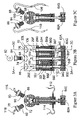
- FIG. 2A is a cross-sectional view of the displacement pump and check valve apparatus of FIG. 2B taken along line 2 A— 2 A.
- FIG. 2B is a front view of the displacement pump and check valve apparatus of FIG. 2A and 2C .
- FIG. 2C is a cross-sectional view of the displacement pump and check valve apparatus of FIG. 2B taken along line 2 C— 2 C.
- FIG. 3A is a cross-sectional view of the displacement pump and check valve apparatus of FIG. 3B taken along line 3 A— 3 A.
- FIG. 3B is a front view of the displacement pump and check valve
- FIG. 3C is a cross-sectional view of the displacement pump and check valve apparatus of FIG. 3B taken along line 3 C— 3 C.
- FIG. 4 is a side view of a displacement pump and check valve apparatus of this invention.
- FIG. 5 is a cross-sectional view of the check valve useful in the present invention.
- the pump apparatus 10 of this invention includes a housing 12 and a motor 16 which effects rotation.
- Housing 32 which can be formed of an opaque or transparent material which is resistant to the liquid being pumped such as acrylic, polyetherether ketone, or the like can be a single piece or a plurality of joined elements.
- Each piston 34 of each pump can be formed of sapphire, glass or a ceramic or the like and is spaced apart from the interior wall 38 of housing 32 to form a barrel 29 .
- a single stroke of each piston 34 during use of the pump will deliver a known volume of liquid depending upon the piston diameter, the barrel diameter and the stroke length.
- the provision of a single element housing provides the advantage that the valve seats and displacement pump of this invention can be replaced simultaneously after the useful life of the pump is completed.
- Motor 16 causes gear box 40 to reciprocate through pulley 41 , and gears 42 , 44 and 46 and gear track 48 .
- Gear box 40 is positioned within track 47 which causes the piston 34 of each pump to move in a repeatable linear path stroke after stroke. As shown in FIG. 4 , the stroke of the pump varies from position 50 and position 52 which typically can be between about 1.5 and 2.0 inches. It is to be understood that any conventional activating apparatus which causes each piston 34 to reciprocate on a linear path can be utilized in the present invention.
- FIGS. 1A , 1 B and 1 C show the embodiment of this invention wherein two liquids are simultaneously pumped without the use of a wash liquid for the pump seals.
- Each piston 34 A and 34 B is positioned within a seal 56 A or 56 B which can be formed, for example of ultra high molecular weight polyethylene (UHMWPE) or the like and optional roulon guide 58 A or 58 B.
- the roulon guides 58 A and 58 B align pistons 34 A and 34 B into seals 56 A and 56 B.
- the pistons 34 A and 34 B reciprocate within seals 56 A and 56 B and roulon guides 54 A and 54 B.
- the pistons 34 A and 34 B are fixedly positioned in ferrules 60 A and 60 B which, in turn, are fixed within arm 62 by knobs 64 A and 64 B. Both pistons move when arm 62 is moved.
- the volume ratio of the liquids delivered from barrels 29 A and 29 B with a single stroke of pistons 34 A and 34 B is controlled by the ratio of the sizes of the pistons 34 A and 34 B.
- the housing 32 can be formed of three pieces, 32 A, 32 B and 32 C.
- Housing piece 32 C includes four valve seats 31 , 33 , 35 and 37 into which are positioned check valves 39 , 41 , 43 and 45 .
- Check valves 39 , 41 , 43 and 45 can have threads 47 , 49 , 51 and 53 to screw the valves 39 , 41 , 43 and 45 into valve seats 31 , 33 , 35 and 37 having internal threads (not shown).
- Housing 32 c can be provided with threads 55 and 57 to secure housings 32 A and 32 B to housing 32 C.
- Check valves 41 and 45 are connected to conduit 59 and 61 which in turn are in fluid communication with a point of use for the fluid (not shown).
- Check valves 39 and 43 are connected with conduits 63 and 65 which, in turn, are connected to a reservoir for the fluid (not shown). In use, when pistons 34 A and 34 B move toward check valves 41 and 45 , check valves 41 and 45 are open and check valves 39 and 43 are closed so that fluid is delivered through check valves 41 and 45 and conduits 59 and 61 to a point of use of the fluids.
- check valves 41 and 45 are closed and check valves 39 and 43 are open so that fluid moves into barrel 29 A and 29 B through check valves 39 and 43 and conduits 63 and 65 from a fluid reservoir.
- FIGS. 2A , 2 B and 2 C show the embodiment of this invention wherein two liquids including a wash liquid for the pump seals are simultaneously pumped.
- Each piston 34 C and 34 D is positioned within a seal 56 C or 56 D which can be formed, from (UHMWPE) or the like and optional roulon guide 58 c or 58 D.
- the roulon guides 58 C and 58 D align pistons 34 C and 34 D into seals 56 C and 56 D.
- the pistons 34 C and 34 D reciprocate within seals 56 C and 56 D and roulon guides 54 C and 54 D.
- the pistons 34 C and 34 D are fixedly positioned in ferrules 60 C and 60 D which, in turn, are fixed within arm 62 A by knobs 64 C and 64 D.
- Both pistons 34 E and 34 F move together when arm 62 A is moved by motor 16 ( FIG. 4 ).
- the volume ratio of the liquids delivered from barrels 29 C and 29 D with a single stroke of pistons 34 E and 34 F is controlled by the ratio of the sizes of the pistons 34 E and 34 F.
- the housing 32 D can be formed of three pieces comprising piece 32 E, 32 F and 32 G.
- Housing piece 32 G includes four valve seats 67 , 69 , 71 and 73 into which are positioned check valves 75 , 77 , 79 and 81 .
- Check valves 75 , 77 , 79 and 81 can have threads 83 , 85 , 87 and 89 to screw the valves 75 , 77 , 79 and 81 into valve seats 67 , 69 , 71 and 73 having internal threads (not shown).
- Housing 32 g can be provided with threads 91 and 93 to secure housings 32 E and 32 F to housing 32 G.
- Check valves 79 is connected to conduit 95 which in turn is connected to a reservoir for wash water (not shown).
- Check valve 81 is connected to conduit 97 which, in turn, is connected to seal 56 C in order to deliver wash water to seal 56 C.
- Conduit 99 is connected to seal 56 C to remove wash water from seal 56 C. The wash water substantially prevents build-up of contaminants within seal 56 C.
- Check valve 75 is connected to conduit 96 which, in turn, is in fluid communication with a reservoir for a fluid (not shown).
- Check valve 77 is connected to conduit 98 which directs pumped fluid to a point of use (not shown).
- check valves 81 and 83 are open and check valves 75 and 79 are closed so that fluid is delivered through check valve 77 and conduits 98 to a point of use of a fluid.
- wash water is delivered through check valve 81 and conduit 97 .
- check valves 77 and 81 are closed and check valves 75 and 79 are open so that fluid moves into barrels 29 C and 29 D through check valves 75 and 79 and conduits 95 and 96 from a fluid reservoir (not shown).
- FIGS. 3A , 3 B and 3 C show the embodiment of this invention wherein three liquids including a wash liquid for the pump seals are simultaneously pumped.
- Each piston 34 G, 34 H and 34 I is positioned within a seal 56 E, 56 F or 56 G which can be formed, from UHMWPE or the like and optional roulon guides 58 E, 58 F or 58 G.
- the roulon guides 58 E, 58 F and 58 G align pistons 34 G, 34 H and 34 I into seals 56 E, 56 F and 56 G.
- the pistons 34 G, 34 H and 34 I reciprocate within seals 56 E, 56 F and 56 G and roulon guides 54 E, 54 F and 54 G.
- the pistons 34 G, 34 H and 34 I are fixedly positioned in ferrules 60 E, 60 F and 60 G which, in turn, are fixed within arm 62 by knobs 64 E, 64 F and 64 G. All three pistons 34 G, 34 H and 34 I move when arm 62 A is moved.
- the volume ratio of the liquids delivered from barrels 29 C, 29 D and 29 E with a single stroke of pistons 34 G, 34 H and 34 I is controlled by the ratio of the sizes of the pistons 34 G, 34 H and 34 I.
- the housing 32 H can be formed of four pieces comprising pieces 32 I, 32 J, 32 K and 32 L.
- Housing piece 32 I includes six valve seats 66 , 68 , 70 , 72 , 74 and 76 into which are positioned check valves 78 , 80 , 82 , 84 , 86 and 88 .
- Check valves 78 , 80 , 82 , 84 , 86 and 88 can have threads e.g., 90 , 92 , 94 and 100 to screw the valves 78 , 80 , 82 , 84 , 86 and 88 into valve seats 66 , 68 , 70 , 72 , 74 and 76 having internal threads (not shown).
- Housing 32 H can be provided with threads 102 , 104 and 106 to secure housings 32 I, 32 J and 32 K to housing 32 H.
- Check valve 88 is connected to conduit 108 which in turn is connected to a reservoir for wash water (not shown).
- Check valve 86 is connected to conduit 110 which, in turn, is connected to seals 56 E and 56 F in order to deliver wash water to seals 56 E and 56 F.
- a conduit 112 connects seal 56 F to seal 56 E so that both seals 56 E and 56 F receive wash water.
- Conduit 114 is connected to seal 56 E to remove wash water from seals 56 E and 56 F.
- Check valve 80 is connected to conduit 116 which, in turn, is in fluid communication with a reservoir for a fluid (not shown).
- Check valve 78 is connected to conduit 118 which directs pumped fluid to a point of use (not shown).
- check valves 78 , 82 and 86 are open and check valves 80 , 84 and 88 are closed so that fluid is delivered through check valves 78 and 82 and conduits 118 and 119 to a point of use of a fluid.
- wash water is delivered through check valve 86 and conduit 110 .
- check valves 78 , 82 and 86 are closed and check valves 80 , 84 and 88 are open so that fluid moves into barrels 29 E, 29 F and 29 G through check valves 80 , 84 , and 88 from a fluid reservoir (not shown).
- valve 41 like valves 39 , 43 and 45 includes a movable ball 101 which moves within valve seat 103 to block either conduit 105 or conduit 107 to effect fluid flow as described above.
Abstract
Description
Claims (10)
Priority Applications (2)
| Application Number | Priority Date | Filing Date | Title |
|---|---|---|---|
| US10/887,627 US7214039B2 (en) | 2004-07-12 | 2004-07-12 | Integrated ratio pump and check valve apparatus |
| PCT/US2005/015370 WO2006016920A2 (en) | 2004-07-12 | 2005-05-04 | Integrated ratio pump and check valve apparatus |
Applications Claiming Priority (1)
| Application Number | Priority Date | Filing Date | Title |
|---|---|---|---|
| US10/887,627 US7214039B2 (en) | 2004-07-12 | 2004-07-12 | Integrated ratio pump and check valve apparatus |
Publications (2)
| Publication Number | Publication Date |
|---|---|
| US20060008369A1 US20060008369A1 (en) | 2006-01-12 |
| US7214039B2 true US7214039B2 (en) | 2007-05-08 |
Family
ID=35541564
Family Applications (1)
| Application Number | Title | Priority Date | Filing Date |
|---|---|---|---|
| US10/887,627 Active 2025-11-08 US7214039B2 (en) | 2004-07-12 | 2004-07-12 | Integrated ratio pump and check valve apparatus |
Country Status (2)
| Country | Link |
|---|---|
| US (1) | US7214039B2 (en) |
| WO (1) | WO2006016920A2 (en) |
Cited By (4)
| Publication number | Priority date | Publication date | Assignee | Title |
|---|---|---|---|---|
| US20100301069A1 (en) * | 2009-05-28 | 2010-12-02 | Ivek Corporation | Pump with wash flow path for washing displacement piston and seal |
| US20110172646A1 (en) * | 2010-01-08 | 2011-07-14 | Medtronic, Inc. | Multi-material single-piece actuator member for miniature reciprocating piston pump in medical applications |
| US9649436B2 (en) | 2011-09-21 | 2017-05-16 | Bayer Healthcare Llc | Assembly method for a fluid pump device for a continuous multi-fluid delivery system |
| US10507319B2 (en) | 2015-01-09 | 2019-12-17 | Bayer Healthcare Llc | Multiple fluid delivery system with multi-use disposable set and features thereof |
Families Citing this family (2)
| Publication number | Priority date | Publication date | Assignee | Title |
|---|---|---|---|---|
| US7837447B2 (en) * | 2007-07-23 | 2010-11-23 | Medica Corporation | Diluter pump for chemistry analyzers |
| CN102330670B (en) * | 2011-09-19 | 2014-12-10 | 中航力源液压股份有限公司 | Method and device for preventing plunger pump from sucking air |
Citations (8)
| Publication number | Priority date | Publication date | Assignee | Title |
|---|---|---|---|---|
| US1546596A (en) * | 1920-06-29 | 1925-07-21 | Hugo Junkers | Fuel pump |
| US3030118A (en) * | 1958-05-13 | 1962-04-17 | Cocker Machine & Foundry Compa | Seal for a rotating shaft |
| US3053195A (en) * | 1959-04-14 | 1962-09-11 | Larkin R Williamson | High pressure hydraulic pump |
| US3943717A (en) * | 1974-01-07 | 1976-03-16 | Caterpillar Tractor Co. | Contaminant removal from a hydraulic cylinder |
| GB2188437A (en) * | 1986-01-30 | 1987-09-30 | Geoservices | Analysis of fluid gas content |
| US4883409A (en) * | 1987-09-26 | 1989-11-28 | Fred Strohmeier | Pumping apparatus for delivering liquid at high pressure |
| FR2639066A1 (en) * | 1987-04-07 | 1990-05-18 | Dosys | Metering pump with a spool |
| US7080975B2 (en) * | 2003-06-25 | 2006-07-25 | Sapphire Engineering, Inc. | Integrated pump and ceramic valve |
-
2004
- 2004-07-12 US US10/887,627 patent/US7214039B2/en active Active
-
2005
- 2005-05-04 WO PCT/US2005/015370 patent/WO2006016920A2/en active Application Filing
Patent Citations (8)
| Publication number | Priority date | Publication date | Assignee | Title |
|---|---|---|---|---|
| US1546596A (en) * | 1920-06-29 | 1925-07-21 | Hugo Junkers | Fuel pump |
| US3030118A (en) * | 1958-05-13 | 1962-04-17 | Cocker Machine & Foundry Compa | Seal for a rotating shaft |
| US3053195A (en) * | 1959-04-14 | 1962-09-11 | Larkin R Williamson | High pressure hydraulic pump |
| US3943717A (en) * | 1974-01-07 | 1976-03-16 | Caterpillar Tractor Co. | Contaminant removal from a hydraulic cylinder |
| GB2188437A (en) * | 1986-01-30 | 1987-09-30 | Geoservices | Analysis of fluid gas content |
| FR2639066A1 (en) * | 1987-04-07 | 1990-05-18 | Dosys | Metering pump with a spool |
| US4883409A (en) * | 1987-09-26 | 1989-11-28 | Fred Strohmeier | Pumping apparatus for delivering liquid at high pressure |
| US7080975B2 (en) * | 2003-06-25 | 2006-07-25 | Sapphire Engineering, Inc. | Integrated pump and ceramic valve |
Cited By (8)
| Publication number | Priority date | Publication date | Assignee | Title |
|---|---|---|---|---|
| US20100301069A1 (en) * | 2009-05-28 | 2010-12-02 | Ivek Corporation | Pump with wash flow path for washing displacement piston and seal |
| US8864475B2 (en) | 2009-05-28 | 2014-10-21 | Ivek Corporation | Pump with wash flow path for washing displacement piston and seal |
| US20110172646A1 (en) * | 2010-01-08 | 2011-07-14 | Medtronic, Inc. | Multi-material single-piece actuator member for miniature reciprocating piston pump in medical applications |
| US8430651B2 (en) | 2010-01-08 | 2013-04-30 | Medtronic, Inc. | Multi-material single-piece actuator member for miniature reciprocating piston pump in medical applications |
| US9649436B2 (en) | 2011-09-21 | 2017-05-16 | Bayer Healthcare Llc | Assembly method for a fluid pump device for a continuous multi-fluid delivery system |
| US9700672B2 (en) | 2011-09-21 | 2017-07-11 | Bayer Healthcare Llc | Continuous multi-fluid pump device, drive and actuating system and method |
| US10507319B2 (en) | 2015-01-09 | 2019-12-17 | Bayer Healthcare Llc | Multiple fluid delivery system with multi-use disposable set and features thereof |
| US11491318B2 (en) | 2015-01-09 | 2022-11-08 | Bayer Healthcare Llc | Multiple fluid delivery system with multi-use disposable set and features thereof |
Also Published As
| Publication number | Publication date |
|---|---|
| WO2006016920A2 (en) | 2006-02-16 |
| WO2006016920A3 (en) | 2007-05-03 |
| US20060008369A1 (en) | 2006-01-12 |
Similar Documents
| Publication | Publication Date | Title |
|---|---|---|
| EP0437261B1 (en) | Pump with multi-port discharge | |
| US4705461A (en) | Two-component metering pump | |
| WO2006016919A2 (en) | Integrated pump and wash pump | |
| IL183337A0 (en) | Volumetric pump with reciprocated and rotated piston | |
| US5145339A (en) | Pulseless piston pump | |
| CA2293516A1 (en) | Reciprocating pumps with linear motor driver | |
| US6162030A (en) | Zero leakage valveless positive fluid displacement device | |
| WO2006016920A2 (en) | Integrated ratio pump and check valve apparatus | |
| KR100358316B1 (en) | Reciprocating Liquid Pump | |
| WO2006016921A2 (en) | Integrated pump and check valve apparatus | |
| US7080975B2 (en) | Integrated pump and ceramic valve | |
| US7278836B2 (en) | Metering pump | |
| US3958903A (en) | Positive displacement device | |
| EP0486556B1 (en) | Pulseless piston pump | |
| JPWO2019151062A1 (en) | Liquid chromatograph | |
| CN220599951U (en) | Linear metering pump and automatic filling equipment | |
| CN112840124B (en) | Accurate constant-flow reciprocating pump | |
| JP3390892B2 (en) | Liquid pressure processing equipment | |
| JP2001082318A (en) | Reciprocating pump device | |
| CN108953092A (en) | A kind of portable oxygen concentrator | |
| JPS6026186A (en) | Reciprocal piston pump | |
| JP2002202051A (en) | Reciprocating pump device | |
| JPS6338692A (en) | Seal device for plunger pump | |
| CA2020472A1 (en) | Pulseless piston pump | |
| GB2355227A (en) | Metering pump |
Legal Events
| Date | Code | Title | Description |
|---|---|---|---|
| AS | Assignment |
Owner name: SAPPHIRE ENGINEERING INC., MASSACHUSETTS Free format text: ASSIGNMENT OF ASSIGNORS INTEREST;ASSIGNOR:ANGOVE, GARRET;REEL/FRAME:015569/0116 Effective date: 20040706 |
|
| STCF | Information on status: patent grant |
Free format text: PATENTED CASE |
|
| AS | Assignment |
Owner name: IDEX HEALTH & SCIENCE LLC, ILLINOIS Free format text: MERGER;ASSIGNOR:SAPPHIRE ENGINEERING, INC.;REEL/FRAME:023510/0340 Effective date: 20081224 |
|
| FPAY | Fee payment |
Year of fee payment: 4 |
|
| SULP | Surcharge for late payment | ||
| REMI | Maintenance fee reminder mailed | ||
| FEPP | Fee payment procedure |
Free format text: PAYOR NUMBER ASSIGNED (ORIGINAL EVENT CODE: ASPN); ENTITY STATUS OF PATENT OWNER: LARGE ENTITY |
|
| REMI | Maintenance fee reminder mailed | ||
| FPAY | Fee payment |
Year of fee payment: 8 |
|
| SULP | Surcharge for late payment |
Year of fee payment: 7 |
|
| MAFP | Maintenance fee payment |
Free format text: PAYMENT OF MAINTENANCE FEE, 12TH YEAR, LARGE ENTITY (ORIGINAL EVENT CODE: M1553); ENTITY STATUS OF PATENT OWNER: LARGE ENTITY Year of fee payment: 12 |