US7216950B2 - Liquid-discharging apparatus, and density adjusting method and system of the same - Google Patents
Liquid-discharging apparatus, and density adjusting method and system of the same Download PDFInfo
- Publication number
- US7216950B2 US7216950B2 US10/855,209 US85520904A US7216950B2 US 7216950 B2 US7216950 B2 US 7216950B2 US 85520904 A US85520904 A US 85520904A US 7216950 B2 US7216950 B2 US 7216950B2
- Authority
- US
- United States
- Prior art keywords
- density
- liquid
- discharging
- droplets
- droplet
- Prior art date
- Legal status (The legal status is an assumption and is not a legal conclusion. Google has not performed a legal analysis and makes no representation as to the accuracy of the status listed.)
- Expired - Fee Related, expires
Links
Images


Classifications
-
- B—PERFORMING OPERATIONS; TRANSPORTING
- B41—PRINTING; LINING MACHINES; TYPEWRITERS; STAMPS
- B41J—TYPEWRITERS; SELECTIVE PRINTING MECHANISMS, i.e. MECHANISMS PRINTING OTHERWISE THAN FROM A FORME; CORRECTION OF TYPOGRAPHICAL ERRORS
- B41J2/00—Typewriters or selective printing mechanisms characterised by the printing or marking process for which they are designed
- B41J2/005—Typewriters or selective printing mechanisms characterised by the printing or marking process for which they are designed characterised by bringing liquid or particles selectively into contact with a printing material
- B41J2/01—Ink jet
- B41J2/205—Ink jet for printing a discrete number of tones
- B41J2/2054—Ink jet for printing a discrete number of tones by the variation of dot disposition or characteristics, e.g. dot number density, dot shape
-
- B—PERFORMING OPERATIONS; TRANSPORTING
- B41—PRINTING; LINING MACHINES; TYPEWRITERS; STAMPS
- B41J—TYPEWRITERS; SELECTIVE PRINTING MECHANISMS, i.e. MECHANISMS PRINTING OTHERWISE THAN FROM A FORME; CORRECTION OF TYPOGRAPHICAL ERRORS
- B41J2/00—Typewriters or selective printing mechanisms characterised by the printing or marking process for which they are designed
- B41J2/005—Typewriters or selective printing mechanisms characterised by the printing or marking process for which they are designed characterised by bringing liquid or particles selectively into contact with a printing material
- B41J2/01—Ink jet
- B41J2/07—Ink jet characterised by jet control
-
- B—PERFORMING OPERATIONS; TRANSPORTING
- B41—PRINTING; LINING MACHINES; TYPEWRITERS; STAMPS
- B41J—TYPEWRITERS; SELECTIVE PRINTING MECHANISMS, i.e. MECHANISMS PRINTING OTHERWISE THAN FROM A FORME; CORRECTION OF TYPOGRAPHICAL ERRORS
- B41J2/00—Typewriters or selective printing mechanisms characterised by the printing or marking process for which they are designed
- B41J2/005—Typewriters or selective printing mechanisms characterised by the printing or marking process for which they are designed characterised by bringing liquid or particles selectively into contact with a printing material
- B41J2/01—Ink jet
- B41J2/135—Nozzles
-
- B—PERFORMING OPERATIONS; TRANSPORTING
- B41—PRINTING; LINING MACHINES; TYPEWRITERS; STAMPS
- B41J—TYPEWRITERS; SELECTIVE PRINTING MECHANISMS, i.e. MECHANISMS PRINTING OTHERWISE THAN FROM A FORME; CORRECTION OF TYPOGRAPHICAL ERRORS
- B41J2/00—Typewriters or selective printing mechanisms characterised by the printing or marking process for which they are designed
- B41J2/005—Typewriters or selective printing mechanisms characterised by the printing or marking process for which they are designed characterised by bringing liquid or particles selectively into contact with a printing material
- B41J2/01—Ink jet
- B41J2/21—Ink jet for multi-colour printing
- B41J2/2121—Ink jet for multi-colour printing characterised by dot size, e.g. combinations of printed dots of different diameter
-
- B—PERFORMING OPERATIONS; TRANSPORTING
- B41—PRINTING; LINING MACHINES; TYPEWRITERS; STAMPS
- B41J—TYPEWRITERS; SELECTIVE PRINTING MECHANISMS, i.e. MECHANISMS PRINTING OTHERWISE THAN FROM A FORME; CORRECTION OF TYPOGRAPHICAL ERRORS
- B41J2/00—Typewriters or selective printing mechanisms characterised by the printing or marking process for which they are designed
- B41J2/315—Typewriters or selective printing mechanisms characterised by the printing or marking process for which they are designed characterised by selective application of heat to a heat sensitive printing or impression-transfer material
- B41J2/32—Typewriters or selective printing mechanisms characterised by the printing or marking process for which they are designed characterised by selective application of heat to a heat sensitive printing or impression-transfer material using thermal heads
- B41J2/35—Typewriters or selective printing mechanisms characterised by the printing or marking process for which they are designed characterised by selective application of heat to a heat sensitive printing or impression-transfer material using thermal heads providing current or voltage to the thermal head
- B41J2/355—Control circuits for heating-element selection
- B41J2/36—Print density control
-
- B—PERFORMING OPERATIONS; TRANSPORTING
- B41—PRINTING; LINING MACHINES; TYPEWRITERS; STAMPS
- B41J—TYPEWRITERS; SELECTIVE PRINTING MECHANISMS, i.e. MECHANISMS PRINTING OTHERWISE THAN FROM A FORME; CORRECTION OF TYPOGRAPHICAL ERRORS
- B41J3/00—Typewriters or selective printing or marking mechanisms characterised by the purpose for which they are constructed
- B41J3/54—Typewriters or selective printing or marking mechanisms characterised by the purpose for which they are constructed with two or more sets of type or printing elements
- B41J3/543—Typewriters or selective printing or marking mechanisms characterised by the purpose for which they are constructed with two or more sets of type or printing elements with multiple inkjet print heads
-
- B—PERFORMING OPERATIONS; TRANSPORTING
- B41—PRINTING; LINING MACHINES; TYPEWRITERS; STAMPS
- B41J—TYPEWRITERS; SELECTIVE PRINTING MECHANISMS, i.e. MECHANISMS PRINTING OTHERWISE THAN FROM A FORME; CORRECTION OF TYPOGRAPHICAL ERRORS
- B41J2202/00—Embodiments of or processes related to ink-jet or thermal heads
- B41J2202/01—Embodiments of or processes related to ink-jet heads
- B41J2202/20—Modules
Definitions
- the present invention relates to a liquid-discharging apparatus including a head equipped with a plurality of juxtaposed liquid-discharging units having respective nozzles, forming dots by landing droplets discharged from the nozzles onto a droplet-landing object, and providing half tones by arranging a dot array, and also relates to a density adjusting method and a density adjusting system for adjusting the density of the dots. More particularly, the present invention is relates to a technique for adjusting density unevenness when the unevenness occurs due to a variation in discharging characteristics of the liquid-discharging units.
- An inkjet printer is known as one of conventional liquid-discharging apparatuses.
- the inkjet printer is equipped with a head including a large number of juxtaposed liquid-discharging units having respective nozzles, forms dots on a sheet of printing paper by discharging ink droplets from the nozzles, and forms an image by arranging arrays of the dots.
- a serial-type inkjet printer performs printing in the main scanning direction (in a direction perpendicular to a feeding direction of a sheet of printing paper by using a known method (see, for example, Japanese Examined Patent Application Publication No. 56-6033) for providing half tones by superimposing dots by reciprocating the head more than once, that is, by applying so-called overprinting.
- a known method see, for example, Japanese Examined Patent Application Publication No. 56-6033
- the first recording is performed with a dot pitch greater than the diameter of a dot
- the second recording is performed by arranging a dot so as to cover the space between adjacent dots generated in the first recording.
- the head of the inkjet printer for example, including thermal liquid-discharging units, can discharge only a constant amount of ink droplet from each nozzle during one discharging operation, except for a special head including a special discharging mechanism formed by utilizing the piezo technology. In other words, a discharge amount of an ink droplet during one discharging operation cannot be controlled.
- a thermal sublimination printer or the like normally having a line head structure has an example countermeasure incorporated therein as described below.
- FIG. 21 illustrates a general method for correcting density unevenness by image processing.
- a density measuring-pattern (test pattern) providing a uniform and constant density is first printed so as to measure a state of density unevenness with respect to each color across the full sheet of paper. Then, the printed result with respect to each color is scanned by an image-scanning apparatus. Since the scanned data includes density information and unevenness information, the average density and coefficients of unevenness over the all pixels are computed.
- a data table obtained by multiplying all positions corresponding to the pixels of an input image by the reciprocals of coefficients of unevenness corresponding to the positions (that is, obtained by computation with an inverse function) is produced and stored.
- Improvement in the printing speed incurs an increase in hardware, memory, and the like, and hence causes a larger size of the printer.
- an object of the present invention is to adjust density unevenness caused by a variation in discharging characteristics of a plurality of liquid-discharging units without incurring a reduction in a printing speed and the like, also without incurring an increase in a hardware, a memory, and the like, when the density of a pixel train formed by a liquid-discharging apparatus including a head equipped with the plurality of juxtaposed liquid-discharging units is adjusted.
- a droplet-discharging command signal is provided to the liquid-discharging apparatus so as to provide a uniform and constant density to all pixel trains lying in the main scanning direction, and a density-measuring pattern is formed by the liquid-discharging apparatus.
- the density of the density-measuring pattern is scanned so as to obtain density information with respect to each pixel train (for example, a difference between the density of each pixel train and the average density of all pixel train, obtained by scanning the densities of all pixel trains), and the obtained density information is stored in a memory installed in the liquid-discharging apparatus or a memory of a computer or the like submitting a droplet-discharging command signal to the liquid-discharging apparatus.
- the liquid-discharging apparatus When a discharge command signal is actually inputted in the liquid-discharging apparatus, on the basis of the density information stored in the memory of the computer or the liquid-discharging apparatus submitting the discharge command signal, the liquid-discharging apparatus is controlled so as to adjust the density of the pixel train corresponding to the discharge command signal by making the number of droplets to be actually discharged from the liquid-discharging units different from the number of droplets discharged in accordance with the discharge command signal. For example, when the density of a pixel train to be adjusted is lower than the average density by 10%, the liquid-discharging apparatus is controlled so as to increase the number of droplets by 10%.
- FIG. 1 is an exploded perspective view of a head of an inkjet printer including a liquid-discharging apparatus according to the present invention:
- FIG. 2 is a plan view of a line head according to an embodiment of the present invention.
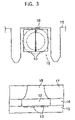
- FIG. 3 provides a plan view and a sectional view, illustrating the detailed arrangement of a heating resistor of the head
- FIGS. 4A to 4C are graphs, each illustrating the relationship between time difference in bubble generations of ink and discharge angle due to divided parts of a heating resistor when the heating resistor is divided into a plurality of parts;
- FIG. 5 illustrates deflection of the discharge direction of an ink droplet
- FIG. 6 illustrates an example in which ink droplets from adjacent liquid-discharging units are landed in a single pixel area, and discharge directions of each ink droplet are set at an even number
- FIG. 7 illustrates an example in which discharge directions of an ink droplet from each liquid-discharging unit are set at an odd number by discharging the ink droplet into right and left symmetrical directions in a defelecting manner and directly below the liquid-discharging unit;
- FIG. 8 illustrates a process of forming each pixel on a sheet of printing paper by the liquid-discharging units, each discharging droplets into two directions (having an even number of discharge directions) in accordance with discharge command signals;
- FIG. 9 illustrates a process of forming each pixel on a sheet of printing paper by the liquid-discharging units, each discharging droplets into three directions (having an odd number of discharge directions) in accordance with discharge command signals;
- FIG. 10 illustrates a general density-adjusting method according to an embodiment of the present invention
- FIG. 11 is a graph illustrating the relationship between the number of discharged droplets and a relative amount of discharged droplets
- FIG. 12 is a graph illustrating a part of density-distribution characteristics, measured at every number of discharge operations per pixel when droplets are discharged from each liquid-discharging unit with four colors of ink;
- FIG. 13 is a table illustrating average values, relative densities of measured densities for colors of yellow (Y), magenta (M), cyan (C), and black (K), and the average relative density for all colors.
- FIG. 14 is a graph of the results shown in FIG. 13 ;
- FIG. 15 illustrates a density-measuring pattern
- FIG. 16 illustrates the relationship among discharge command signals, liquid-discharging units, and pixel trains
- FIG. 17 illustrates example round-off computation according to the present embodiment
- FIG. 18 is a table illustrating differences in computed results between a round-off method according to the present embodiment (according to a method of considering an error into the subsequent input) and a simple round-off method;
- FIG. 19 is a graph of outputs shown in the table in FIG. 18 , putting the outputs according to the simple round-off method and those according to the error-considered round-off method according to the present embodiment in contrast with each other;
- FIG. 20 illustrates an example graph obtained by passing both outputs through an appropriate low-pass filter so as to attenuate high-frequency components of these values
- FIG. 21 illustrates a general method for correcting density unevenness by image processing.
- ink droplet means a very small amount (for example, a few picolillters) of ink (liquid) discharged from a nozzle 18 of a liquid-discharging unit, which will be described later.
- a term “dot” means one form of an ink droplet landed on a recording medium such as a sheet of printing paper.
- pixel is a minimum unit of an image
- pixel area means an area in which a pixel is formed.
- a pixel (1-step gradation) with no pixel a pixel (2-step gradation) with a single dot, or a pixel (3 or more-step gradation) with a plurality of dots is respectively formed. That is, zero, one, or a plurality of pieces of dots corresponds to a single pixel area, and an image is formed by arranging a large number of these pixels on a recording medium.
- main scanning direction means a transporting direction of a sheet of printing paper in a line-type printer equipped with a line head.
- main scanning direction and sub scanning direction are respectively defined as a moving direction of a head (a width direction of a sheet of printing paper) and a transporting direction of a sheet of printing paper, that is, a direction perpendicular to the main scanning direction.
- a term “pixel train” means a group of pixels lining in the main scanning direction. Accordingly, in a line-type printer, a group of pixels lining in the transporting direction of a sheet of printing paper form a pixel train. In the meantime, in a serial-type printer, a group of pixels lining in the moving direction of a head form a pixel train.
- a term “pixel line” means a line perpendicular to a pixel train, for example, in a line-type printer, a line along which liquid-discharging units (or nozzles) are juxtaposed side by side.
- FIG. 1 is an exploded perspective view of a head 11 of the printer.
- a nozzle sheet 17 shown in FIG. 1 in an exploded manner is bonded to the upper surface of a barrier layer 16 .
- the head 11 includes a substrate member 14 including a semiconductor substrate 15 composed of silicon or the like and heating resistors 13 deposited on one of the surfaces of the semiconductor substrate 15 .
- the heating resistors 13 are electrically connected to an external circuit, having a conducting portion (not shown) formed on the semiconductor substrate 15 , interposed therebetween.
- the barrier layer 16 is composed of, for example, photosensitive cyclized rubber resist or exposure-curable dry film resist and is laminated on the entire surface on which the heating resistors 13 of the semiconductor substrate 15 are formed, and then an unnecessary part thereof is removed by lithography.
- the nozzle sheet 17 having the plurality of nozzles 18 formed therein is composed of nickel by electroforming, for example, and is bonded to the upper surface of the barrier layer 16 such that the positions of the nozzles 18 agree with those of the corresponding heating resistors 13 , that is, such that the nozzles 18 are placed so as to face the corresponding heating resistors 13 .
- the head 11 also includes ink chambers 12 , each defined by the substrate member 14 , the barrier layer 16 , and the nozzle sheet 17 so as to surround the corresponding heating resistor 13 . That is, in the figure, the substrate member 14 , the barrier layer 16 , and the nozzle sheet 17 serve as the bottom wall, the side wall, and the top wall of each ink chamber 12 , respectively. With this structure, each ink chamber 12 has an opening area extending toward a right front direction in FIG. 1 so as to be in communication with the corresponding ink-flow channel (not shown).
- a single of the head 11 generally includes the ink chambers 12 of an order of 100 units and the heating resistors 13 disposed in the corresponding ink chambers 12 .
- the head 11 In response to a command from a control unit of the printer, the head 11 uniquely selects each of the heating resistors 13 and discharges ink in the ink chamber 12 corresponding to the selected heating resistor 13 from the nozzle 18 facing the ink chamber 12 .
- the ink chambers 12 are filled with ink from an ink tank (not shown) connected to the head 11 .
- a pulse current is fed to the selected heating resistor 13 for a short.period of time, for example, 1 to 3 ⁇ sec, the heating resistor 13 is quickly heated.
- a gaseous-phase ink bubble is generated in ink in the ink chamber 12 , lying in contact with the heating resistor 13 , and a certain volume of ink is pushed away due to expansion of the ink bubble (that is, ink is brought to boiling).
- ink having substantially the same volume as that of the ink lying in contact with the nozzle 18 and pushed away as mentioned above is discharged from the corresponding nozzle 18 as an ink droplet, landed on a sheet of printing paper, and forms a dot (pixel).
- a component made up by one of the ink chambers 12 , the heating resistor 13 disposed in the ink chamber 12 , and the nozzle 18 disposed above the ink chamber 12 is referred to as a liquid-discharging unit. That is, the head 11 has a plurality of liquid-discharging units therein which are juxtaposed side by side.
- FIG. 2 is a plan view of the line head 10 according to the embodiment, illustrating four of the heads 11 ; (N ⁇ 1)-th, N-th, (N+1)-th, and (N+2)-th heads 11 .
- a plurality of components head chips is juxtaposed side by side, each formed by the head 11 from which the nozzle sheet 17 is removed in FIG. 1 .
- a single sheet of the nozzle sheet 17 having the nozzles 18 formed therein so as to correspond to the respective liquid-discharging units of all head chips is bonded to the upper surfaces of these head chips.
- all heads 11 are disposed such that a pitch between the nozzles 18 lying at the ends of the mutually adjacent heads 11 , that is, such that, as shown in a detailed A-part of FIG. 2 , a space between the nozzles 18 respectively lying at the right and left ends of the N-th and (N+1)-th heads 11 is the same as that between adjacent nozzles 18 of each head 11 .
- the head 11 includes discharge-direction-changing means.
- the discharge-direction-changing means changes the discharge direction of an ink droplet discharged from each nozzle 18 into a plurality of directions within a direction along which the nozzles 18 (liquid-discharging units) are juxtaposed side by side and has a structure as described below.
- FIG. 3 provides a plan view and a sectional view, illustrating the detailed arrangement of the heating resistor 13 of the head 11 .
- the position of the nozzle 18 is indicated by a dotted-chain line.
- the head 11 has two-way-divided parts of the heating resistor 13 juxtaposed side by side in a single of the ink chamber 12 . Also, the divided parts of the heating resistor 13 are juxtaposed side by side in the direction (the horizontal direction in FIG. 3 ) along which the nozzles 18 are juxtaposed side by side.
- FIGS. 4A and 4B are graphs obtained by computer simulation, illustrating the relationship between time difference in bubble generations and discharge angle due to the divided parts of the heating resistor 13 when the heating resistor 13 is divided into a plurality of parts as set forth in the present embodiment.
- the X-direction (direction shown by the vertical axis ⁇ x in FIG. 4A , not meaning the horizontal direction of these graphs) is the direction along which the nozzles 18 (the heating resistors 13 ) are juxtaposed side by side are juxtaposed side by side
- the Y-direction (direction shown by the vertical axis ⁇ y in FIG.
- FIG. 4C is a graph of measured data when a difference in generation times of bubbles of ink on the two-way-divided parts of the heating resistors 13 is defined as a reflecting current given by half a difference in currents fed to the two-way-divided parts of the heating resistors 13 and is represented by the horizontal axis, and a discharge angle of an ink droplet (in the X-direction) is defined as a deflecting amount of the ink droplet at its landing position (measured when the distance between the nozzle 18 and the landing position is set at about 2 mm) and is represented by the vertical axis.
- a discharge angle of an ink droplet in the X-direction
- an ink droplet is discharged in a deflecting manner by setting a current of the main power supply of the heating resistor 13 at 80 mA, and the defelecting current is superimposed on one of the two-way-divided parts of the heating resistor 13 .
- the above-mentioned feature is utilized in the present embodiment. That is, by disposing the two-way-divided parts of the heating resistors 13 and, by feeding different amounts of currents to these divided parts of the heating resistor 13 from each other, the liquid-discharging apparatus is controlled so as to cause ink on the divided parts of the heating resistor 13 to generate an ink droplet at different times from each other and accordingly to deflect the discharge direction of the ink droplet.
- the two-way-divided parts of the heating resistors 13 do not have a common resistance as each other due to a manufacturing error or the like, bubble generation times of the divided parts of the heating resistor 13 are different from each other, and an ink droplet is not discharged at a right angle on a sheet of printing paper, a landing position of the ink droplet is deflected from its originally intended position.
- bubble generation times of ink on both divided parts of the heating resistor 13 are controlled so as to be identical by feeding different amounts of current to the two-way-divided parts of the heating resistors 13 from each other, the ink droplet can be discharged at a right angle.
- FIG. 5 illustrates deflection of the discharge direction of an ink droplet.
- the ink droplet i is discharged orthogonal to the discharging surface of the corresponding nozzle 18 , the ink droplet i is discharged without deflection as shown by the dotted arrow indicated in FIG. 5 .
- the discharge direction of the ink droplet i is deflected such that its discharge angle is deflected by ⁇ from the vertical direction (that is, deflected along either Z 1 or Z 2 direction shown in FIG. 5 )
- the distance H between the top of the nozzle 18 and a sheet of printing paper P is about 1 to 2 mm, it is assumed that the distance H is held at an almost constant value of about 2 mm.
- the reason for holding the distance H at an almost constant value is such that, when a variance in the distance H causes the landing position of the ink droplet i to vary. That is, when an ink droplet i is discharged from the nozzle 18 orthogonal to the plane of the sheet of printing paper P, even when the distance H varies somewhat, the landing position of the ink droplet i does not vary. In contrast to this, when an ink droplet i is discharged in a deflecting manner as described above, the landing position of the ink droplet i varies in accordance with a variance in the distance H.
- a discharge control of an ink droplet is performed by discharge-direction-controlling means as described below.
- the discharge-direction-controlling means controls at least two nearby liquid-discharging units so as to discharge ink droplets into respectively different directions and to land the discharged droplets on a single pixel train so as to form a single pixel train or in a single pixel area so as to form a single pixel.
- the discharge-direction-controlling means it is arranged such that an ink droplet from each nozzle 18 is variably discharged into one of an even number 2 J (J: a positive integer) of directions in accordance with a control signal made up by J bits, and also the interval between the remotest landing positions of two ink droplets of those discharged into the 2 J directions is (2 J ⁇ 1) times the interval between the adjacent nozzles 18 .
- 2 J a positive integer
- the means for controlling a discharge direction it is arranged such that an ink droplet from the nozzle 18 is variably discharged into one of an odd number (2 J +1) of directions in accordance with a control signal made up by (J bits+1), and also the interval between the remotest landing positions of two ink droplets of those discharged into the (2 J +1) directions is 2 J times the interval between the adjacent nozzles 18 .
- discharge directions of an ink droplet can be set so as to right and left symmetrical directions within the direction along which the nozzles 18 are juxtaposed side by side.
- discharge directions of an ink droplet can be set at an odd number.
- discharge directions of an ink droplet from each nozzle 18 can be set at an even number of right and left symmetrical directions within the direction along which the nozzles 18 are juxtaposed side by side
- the discharge directions of an ink droplet can be set at an odd number, by using a part of the control signal made up by +1, the ink droplet can be also discharged directly below the nozzle 18 .
- the discharge directions can be also set at an odd number of right and left symmetrical directions (represented by reference characters “a” and “c” shown in FIG. 7 ) and a direction directly below the nozzle 18 (represented by a reference character “b” in FIG. 7 ).
- ink droplets from a nozzle N can be landed not only in a pixel area N lying directly below the nozzle N but also in pixel areas (N ⁇ 1) and (N+1) adjacent to the pixel area N.
- the landing positions of ink droplets are opposed to the nozzles 18 .
- each liquid-discharging unit can land ink droplets at positions lying along the direction along which the liquid-discharging units are juxtaposed and given by the following expression with respect to its vertical center axis: ⁇ (1 ⁇ 2 ⁇ X) ⁇ P (P: a positive integer).
- FIG. 8 illustrates a process of forming each pixel on a sheet of printing paper by the liquid-discharging units, each discharging droplets into two directions (having an even number of discharge directions) in accordance with discharge command signals sent in parallel to the head 11 .
- the discharge command signals correspond to image signals.
- the number of gradations of discharge command signals of pixels N, (N+1), and (N+2) are respectively set at 3, 1, and 2.
- a discharge command signal of each pixel is sent to predetermined liquid-discharging units at an interval of “a” or “b”, and also, each liquid-discharging unit discharges an ink droplet at the above-mentioned interval “a” or “b”.
- the intervals “a” and “b” correspond to time slots “a” and “b” respectively.
- a plurality of dots is formed in a single pixel area, for example, during an interval of “a” plus “b” in accordance with the number of gradations of the corresponding discharge command signal.
- discharge command signals of the pixels N and (N+2) are respectively sent to liquid-discharging units (N ⁇ 1) and (N+1).
- the liquid-discharging unit (N ⁇ 1) discharges an ink droplet in the “a” direction in a deflecting manner so as to be landed at the position of the pixel N on a sheet of printing paper.
- the liquid-discharging unit (N+1) discharges an ink droplet in the “a” direction in a deflecting manner so as to be landed at the position of the pixel (N+2) on the sheet of printing paper.
- the pixel N is formed by two dots corresponding to the number of gradations; 3.
- At least two nearby liquid-discharging units can be controlled so as to discharge ink droplets into respectively different directions and to land the discharged droplets on a single pixel train so as to form a pixel train or in a single pixel area so as to form a pixel.
- FIG. 10 illustrates a general density-adjusting method according to the embodiment and corresponding to that of a known art shown in FIG. 21 .
- the liquid-discharging apparatus upon receipt of a discharge command signal of ink droplets, on the basis of density information and relationship between the number and the density of ink droplets, both previously obtained with respect to each pixel train, the liquid-discharging apparatus is controlled so as to adjust the density of the pixel train corresponding to the discharge command signal by making the number of ink droplets to be actually discharged from the liquid-discharging units different from the number of ink droplets discharged in accordance with the discharge command signal.
- density adjustment is performed with respect to each pixel train not with respect to each liquid-discharging unit.
- a single pixel train is formed by using a plurality of liquid-discharging units as described in the present embodiment
- by performing density adjustment with respect to each pixel train discharging characteristics peculiar to the individual liquid-discharging units are not needed to be especially taken into consideration.
- the density adjustment can be performed by common signal processing regardless of whether an ink droplet is discharged in a deflecting manner or not.
- the density-adjusting method has a greatly different point from a known art in that density adjustment processing is performed after performing image processing and gradation processing.
- image processing adjusting brightness and contrast, correcting a ⁇ characteristic, and so forth
- gradation processing including error diffusion are performed on the assumption that discharging characteristics of all liquid-discharging units are uniform, and density adjustment processing is performed in a step after the image processing and as close as possible to a step of discharging an ink droplet.
- gradation processing including image processing and error diffusion is performed on the assumption that the density of dot.arrays formed by all liquid-discharging units is constant, and the liquid-discharging apparatus is controlled so as to adjust the density of a pixel train corresponding to a discharge command signal converted after the gradation processing by discharging a different number of ink droplets from the liquid-discharging units, from the number of droplets discharged in accordance with the discharge command signal.
- a specific example of the density-adjusting method according to the present embodiment will be described.
- a printer as used in the present embodiment since an accumulated amount of discharged ink-droplets is in proportion to the number of ink droplets, and the density of ink droplets is expressed by the ⁇ -th power of the number of the ink droplets, a recording signal, in particular, the number of discharged ink-droplets in this embodiment, and the obtained density have a functional relationship with each other.
- FIG. 11 is a graph illustrating the relationship between the number of discharged droplets and a relative amount of discharged droplets.
- cases of discharging a normal amount, a large amount, and a small amount of a single droplet are illustrated by straight lines ( 2 ), ( 1 ), and ( 3 ), respectively.
- each liquid-discharging unit that is, a discharge amount of an ink droplet discharged once from the liquid-discharging unit
- the total amounts of ink droplets discharged from the liquid-discharging units can be made identical.
- ink droplets are discharged from each liquid-discharging unit with four colors of ink, and a density-distribution characteristic of the droplets at every number of discharged droplets is measured.
- FIG. 12 illustrates a part of the measured results. In FIG. 12 , yellow (Y) ink is used.
- the vertical and horizontal axes of FIG. 12 respectively indicate a value obtained such that output (brightness) levels tare subtracted from an 8 bit output (255) levels and the number (0 to 6) of discharged ink-droplets per each pixel. Also, each ellipse shown in FIG. 12 indicates a density-distribution area.
- the densities of An and An′ can be made equal to each other.
- a density-measuring pattern (test pattern) formed in accordance with a discharge command signal providing a constant density to all pixel trains is printed by the liquid-discharging apparatus, in a state in which density adjustment and the like are not performed at all.
- the density-measuring pattern is printed with respect to each color.
- each printed result is scanned by an image-scanning apparatus such as an image scanner so as to detect the density of each pixel train.
- the printed result can be scanned by a digital camera or the like other than an image scanner, disposed independently from the printer, it can be scanned by an image-scanning apparatus disposed in the printer, for example, next to the line head 10 .
- an image-scanning apparatus disposed in the printer, for example, next to the line head 10 .
- an image-scanning apparatus may be disposed downstream of the line head 10 (so as to scan a printed image after a sheet of printing paper is printed.
- FIG. 15 illustrates an example density-measuring pattern.
- the density-measuring pattern is formed by a plurality of pairs of belt-shaped patterns, each formed by dots arranged so as to extend in the direction along which the liquid-discharging units are juxtaposed side by side, and each pair formed with respect to each color, having a predetermined space therebetween.
- the reason for forming a pair of patterns is as below: since markers (pixel trains having no dots therein) are inserted at predetermined positions of each pattern for determining how-manieth a pixel train in question is disposed with respect to these markers, the densities of pixel trains lying in parts of each pattern where the markers are inserted cannot be measured. To solve this problem, a pair of patterns are recorded.
- the density of the pixel train is scanned from one of the pair of patterns including no makers.
- the density of any one of the patters may be scanned, or the densities of both patterns may be scanned so as to provide the average thereof.
- each pattern has a marker disposed therein every 32 pixel trains. Also, a marker included in one of two patterns with respect to each color lies between two markers included in the other pattern. With this arrangement, when two patterns are viewed as a single pattern with respect to each color, the single pattern has a marker disposed therein every 16 pixel trains.
- the pattern has no markers inserted therein, there is a risk of unreliably determining that how-manieth a pixel train in question is disposed.
- the densities of the pixel trains shown in FIG. 15 are scanned in the order from the leftmost one, there is a risk of occurrence of a greater position error as being farther away from the left end.
- the density information does not accurately indicate the position of the corresponding pixel train, density adjustment cannot be accurately performed. Accordingly, the positions of markers are periodically scanned so as to determine how-manieth a pixel train in question lies with respect to the markers.
- the densities of the pixel trains shown in FIG. 15 are scanned in the order from the leftmost end, there are 15 pixel trains on the left side of the first marker (included in the lower one of the two patterns in the figure).
- the pixel train lying directly above the first marker and included in the upper pattern is detected as the 16th pixel train.
- one marker is inserted into in the upper and lower patterns every 16 pixel trains.
- One of the pixels forming the density-measuring pattern has at least one dot and may have an appropriate number of dots as long as it is acceptable. Although the greater number of dots the better in order to reduce an error caused by fluctuation of an amount of a droplet of each dot, too many dots cause overlaying with the adjacent dots and difficulty in measuring the density of each pixel.
- one pixel is formed by two dots by way of example. Meanwhile, each liquid-discharging unit used in the present embodiment discharges a droplet having a volume of 4.5 pl (pico-litters) at every discharge operation.
- the liquid-discharging apparatus is controlled so as to change the number of ink droplets in accordance with a discharge command signal with respect to each pixel train. Such a control of changing the number of ink droplets as described above is independently performed with respect to each color.
- the number of discharged droplets is set greater than N.
- the number of discharged droplets is set smaller than N.
- density information is previously stored in a memory of the printer, and, after the printer receives a discharge command signal from an external apparatus such as a computer, the number of discharged ink-droplets is changed on the basis of the stored density information.
- the density information is previously stored in an external apparatus such as a computer, and the discharge command signal in which the density is adjusted in accordance with the density information (the number of discharged ink-droplets is changed) may be sent to the printer.
- FIG. 16 illustrates the relationship among discharge command signals (electrical signal trains), liquid-discharging units, and pixel trains.
- a train of the liquid-discharging units (a train of the nozzles 18 ) is formed by N 1 to N 7 liquid-discharging units.
- discharge command signals are represented by S 1 to S 6 .
- pixel trains formed in accordance with these discharge command signals S 1 to S 6 are represented by P 1 to P 6 .
- the pixel train P 2 is formed in accordance with the discharge command signal S 2 so as to have two pieces of dots.
- the discharge command signals are sent to a plurality of neighboring liquid-discharging units, and a single pixel train is formed by these liquid-discharging units. More particularly, as in FIG. 16 , the liquid-discharging apparatus is controlled such that, upon receipt of a discharge command signal, ink droplets are discharged from a liquid-discharging unit lying directly above a pixel train to be formed and also from liquid-discharging units lying on both sides of the pixel train. Accordingly, an example shown in FIG. 16 illustrates the second form of the controlling means in the same fashion as that shown in the foregoing FIG. 9 .
- the pixel train P 3 is formed so as to have 3 dots.
- a first part of the discharge command signal is sent to the liquid-discharging unit N 4 , and the liquid-discharging unit N 4 discharges an ink droplet leftward in the figure in a deflecting manner so as to form a dot of the pixel train P 3 .
- a second part of the discharge command signal is sent to the liquid-discharging unit N 3 , and the liquid-discharging unit N 3 discharges an ink droplet without deflection so as to form another dot of the pixel train P 3 .
- a third part of the discharge command signal is sent to the liquid-discharging unit N 2 , and the liquid-discharging unit N 2 discharges an ink droplet rightward in the figure in a deflecting manner so as to form another dot of the pixel train P 3 .
- the pixel train Pn has a characteristic averaged by the discharging characteristics of three liquid-discharging units. Accordingly, the characteristic is possibly corrected even when one of the liquid-discharging units has a discharging problem.
- each pixel train is not always formed by a plurality of liquid-discharging units.
- the head may have a structure in which a single of the heating resistor 13 is disposed in a single of the ink chamber 12 so as to form the pixel train by discharging ink droplets from all nozzles 18 in a direction orthogonal to the plane of a sheet of printing paper.
- the density of the pixel train corresponding to the liquid-discharging unit cannot be corrected.
- the density can be corrected to a certain degree by, for example, increasing the numbers of discharged droplets of the liquid-discharging units adjacent to the foregoing liquid-discharging unit, at least the density of the pixel train corresponding to the liquid-discharging unit having a discharging problem is different from those of the other pixel trains, whereby it is difficult to make the difference indistinctive.
- a single discharge command signal is allotted into a plurality of (3 in the example shown in FIG. 16 ) of liquid-discharging units so as to form a single pixel train by the plurality of liquid-discharging units as in the present embodiment, the above density can be completely corrected.
- the density of the single pixel train is about two third (low density of about 33%).
- the original number of ink droplets is 3, a pixel train can be formed so as to have a normal density by changing the number to 6, even when one of the liquid-discharging units has a discharging problem.
- the number of discharged ink-droplets is in reality must be an integer.
- the computed number is converted into an integer by round-off processing.
- the liquid-discharging apparatus upon receipt of a droplet-discharging command signal, on the basis of the density information and the relationship between the number and the density of discharged droplets with respect to the corresponding pixel trains the number of density-adjusted discharged droplets corresponding to the number of droplets discharged in accordance with the discharge command signal is computed, and only a high-order part corresponding to the number of ink droplets to be discharged from the liquid-discharging units is extracted by rounding off the computed result.
- the liquid-discharging apparatus is controlled so as to discharge the number of droplets from the liquid-discharging units, corresponding to the extracted higher-order part.
- a difference between the foregoing computed result and the extracted higher-order part is computed, and the liquid-discharging apparatus is controlled so as to add the computed difference to the number of ink-droplets discharged in accordance with the subsequent discharge command signal.
- FIG. 17 illustrates an example of round-off computation according to the present embodiment.
- an input value is equal to 1, and the number of corrections is 140.
- the above output value is added to a fraction of a previously computed result (the fraction in the example shown in FIG. 17 is zero) by an adder 53 , and the added result is outputted by a fraction addition register 54 .
- the output value “00100011” is subjected to round-off processing.
- the fourth bit is rounded off, and the high 3 bits are outputted. That is, a value of the high 3 bits “001” is sent to the line head 10 as an output, Also, the rounded-off result is converted into a two's complement number in order to make signs identical to each other, saved in an output register 55 , and is inputted into an adder 56 for being subjected to round-off processing.
- an output value of the fraction addition register 54 is inputted into the adder 56 , and the sum of both values is saved in a fraction output register 57 . Since this value is inputted into the adder 53 in the subsequent computation, the computation error is considered.
- FIG. 18 is a table illustrating differences in computed results between a round-off method according to the present embodiment (according to a method of considering a computation error in the subsequent input) and a simple round-off method.
- this external input corresponds to the number of discharged ink-droplets for eliminating the deviation of the density.
- the first external input of “1.200” means that when the number of discharged ink-droplets is set at 1.2, the deviation of the density is eliminated.
- the previous error “0.200” is added to “1.161”, and the obtained result “1.361” is rounded off.
- outputs according to the simple round-off method are continuously equal to “1” despite of fluctuation of the external input, while outputs according to the error-considered round-off of the present embodiment fluctuate in the range from “0” to “2”.
- FIG. 19 is a graph of outputs shown in the table in FIG. 18 .
- the outputs according to the simple round-off method and those of the error-considered round-off method according to the present embodiment are put contrast with each other.
- the outputs according to the simple round-off method show a square form like a rectangular waveform in contrast to a smooth sinusoidal waveform of inputs. That is, since all deviations from the sinusoidal waveform indicate computation errors, as the smoother the form of the input signals becomes, the more the errors become distinguish.
- FIG. 20 illustrates an example graph obtained by passing both outputs through an appropriate low-pass filter so as to attenuate high-frequency components of these values.
- bits greater than processing bits normally used in the corresponding system are allotted to the errors so as to ease them or to bring them under control at a practically problem-free level.
- the head of the serial-type printer is equivalent to the head 11 as one of those of the line head 10 and is fixed at a position rotated by 90 degrees relative to that of a line-type printer.
- a direction along which liquid-discharging units are arranged is the sub-scanning direction of the serial-type printer.
- a density-measuring pattern is formed on a sheet of printing paper by providing a droplet-discharging command signal for providing a uniform and constant density to all pixel trains lying in the moving direction of the head (in the main scanning direction of the serial-type printer) and by discharging a predetermined number of ink droplets from each liquid-discharging unit.
- a droplet-discharging command signal for providing a uniform and constant density to all pixel trains lying in the moving direction of the head (in the main scanning direction of the serial-type printer) and by discharging a predetermined number of ink droplets from each liquid-discharging unit.
- the liquid-discharging apparatus upon receipt of a droplet-discharging command signal, on the basis of the previously obtained density information of the corresponding pixel train and relationship between the number and the density of discharged droplets with respect to each pixel train, by making the number of droplets to be actually discharged from the liquid-discharging units different from the number of discharged ink-droplets in accordance with the discharge command signal different, the liquid-discharging apparatus is controlled so as to adjust the density of the pixel train corresponding to the discharge command signal.
- An electrostatic discharging-type energy-generating element is formed by a diaphragm and two electrodes disposed under the diaphragm having an air layer interposed therebetween.
- a voltage of a certain value is applied on the two electrodes so as to bend the diaphragm downward, and then, the voltage is changed to zero so as to release an electrostatic force.
- an ink droplet is discharged by utilizing an elastic force of the diaphragm returning to its original state.
- the two energy-generating elements are arranged so as to generate energy at different timings or to have different voltages applied thereon.
- the piezo-type energy-generating element is a laminate formed by a piezo element having electrodes on both surfaces thereof and a diaphragm.
- a voltage is applied on the electrodes on both surfaces, the piezoelectric effect of the piezo element causes the diaphragm to produce a bending moment and accordingly to be bent and deformed.
- An ink droplet is discharged by utilizing this deformation.
- density unevenness caused by a variation in discharging characteristics of the liquid-discharging units can be adjusted without incurring a reduction in printing speed and the like and also without incurring an increase in hardware, memory, and the like.
Abstract
Description
ΔL=H×tan θ.
±(½×X)×P (P: a positive integer).
M1=A1×N,
M2=A2×N, and
M3=A3×N,
M=A1×N1=A2×N2=A3×N3.
I=An×N γ.
I=An×N 0.571.
An×N 0.571 =An′×N′ 0.571, or
N′=N×(An/An′)1.75.
Y=1.2−cos {(π/80)X} (X: No. of calculation order shown in the table).
- (1) In the present embodiment, although a difference between the average density and the density of each pixel train is computed, and the density of each pixel train is adjusted in accordance with the difference, a threshold of the difference for determining whether or not performing density adjustment is decided on a voluntary basis. For example, when density adjustment is performed even when there is a small difference between the density of each pixel train and the average density, all pixel trains are provided with a further uniform density although more processing operations are accordingly needed. On the contrary, when density adjustment is performed only with respect to a pixel train having density unevenness to an extent to which a human eye visually determines as an insufficient density, operations of the density adjustment can be made fewer.
- (2) In the present embodiment, although the
line head 10 is used by way of example, the present invention is not limited to theline head 10 and is applicable to a serial-type printer having a structure in which ink droplets are discharged while moving a head in the main scanning direction and in which a sheet of printing paper is transported in the sub-scanning direction.
- (3) When the present inventing is applied to a serial-type printer, the head discharging an ink droplet in a reflecting manner as described in the present embodiment may be used, or a head discharging an ink droplet from a nozzle without reflection only in a direction substantially orthogonal to the plane of a sheet of printing paper may be used.
- (4) Although droplets are discharged into two directions or three directions by way of example, with the discharge-direction-controlling means according to the present embodiment, droplets may be discharged into any number of directions. In other words, arbitrary number of liquid-discharging units may be used for forming a single pixel train.
- (5) In the present embodiment, although times (bubble generation times) of ink droplets on two-way-divided parts of the
heating resistors 13 needed for being brought to boiling are made different from each other by feeding different currents to the two-way-divided parts of eachheating resistor 13, the present invention is not limited to the above structure. Alternatively, the liquid-discharging apparatus may have a structure in which the two-way-divided parts having a common resistance, of theheating resistor 13 are juxtaposed, and a current is fed to the divided parts at different timings. For example, respectively independent switches are disposed to the divided parts of theheating resistor 13, and when the switches are turned on at respectively different timings, ink droplets on the divided parts of theheating resistor 13 are brought to boiling at different times from each other. In addition, a combination of a method of feeding different currents to the respective parts of theheating resistor 13 and another method of feeding a current to the same at respectively different timings may be possible. - (6) In the present embodiment, although the two-way-divided parts of the
heating resistor 13 are juxtaposed in a single of theink chamber 12 since the way of dividing theheating resistor 13 into two parts is a proved technique from the viewpoint of satisfactory durability, and also, the circuitry of theheating resistors 13 can be made simple, the present invention is not limited to the above structure. Alternatively, three or more divided parts of theheating resistor 13 may be juxtaposed in a single of theink chamber 12. - (7) In the present embodiment, although the
heating resistor 13 is used by way of example, alternatively, a heating element may be used, or an energy-generating element such as an electrostatic discharging-type or piezo-type energy-generating element may be used.
- (8) In the above-described embodiment, the discharge direction of an ink droplet is deflected in the direction along which the
nozzles 18 are juxtaposed side by side since the divided parts of the dividednozzle 18 are juxtaposed side by side in the same direction. Meanwhile, the deflecting direction of an ink droplet is not always required to completely agree with the direction along which thenozzles 18 are juxtaposed side by side. Even when a small amount of misalignment remains therebetween, substantially the same effect can be expected as in the case where the deflecting direction of an ink droplet agrees completely with the direction along which thenozzles 18 are juxtaposed side by side. - (9) The round-off processing and the like described in the present embodiment can be achieved not only by a hardware (an operation circuit, or the like) but also by software.
- (10) Although the
head 11 is used in a printer in the present embodiment by way of example, thehead 11 according to the present invention is applicable not only to a printer, but also to a variety of liquid-discharging apparatuses including an apparatus discharging a solution containing DNA for detecting a biological specimen, for example.
Claims (21)
Applications Claiming Priority (2)
| Application Number | Priority Date | Filing Date | Title |
|---|---|---|---|
| JP2003156449A JP4241195B2 (en) | 2003-06-02 | 2003-06-02 | Concentration adjustment method for liquid ejection device, concentration adjustment system for liquid ejection device, and liquid ejection device |
| JPJP2003-156449 | 2003-06-02 |
Publications (2)
| Publication Number | Publication Date |
|---|---|
| US20050001866A1 US20050001866A1 (en) | 2005-01-06 |
| US7216950B2 true US7216950B2 (en) | 2007-05-15 |
Family
ID=33157131
Family Applications (1)
| Application Number | Title | Priority Date | Filing Date |
|---|---|---|---|
| US10/855,209 Expired - Fee Related US7216950B2 (en) | 2003-06-02 | 2004-05-27 | Liquid-discharging apparatus, and density adjusting method and system of the same |
Country Status (6)
| Country | Link |
|---|---|
| US (1) | US7216950B2 (en) |
| EP (1) | EP1484183A3 (en) |
| JP (1) | JP4241195B2 (en) |
| KR (1) | KR101074591B1 (en) |
| CN (2) | CN101229725B (en) |
| SG (1) | SG137685A1 (en) |
Cited By (8)
| Publication number | Priority date | Publication date | Assignee | Title |
|---|---|---|---|---|
| US20070109606A1 (en) * | 2005-11-16 | 2007-05-17 | Seiko Epson Corporation | Method of correcting ejection pattern data, apparatus for correcting ejection pattern data, liquid droplet ejection apparatus, method of manufacturing electro-optic device, electro-optic device, and electronic device |
| US8995022B1 (en) | 2013-12-12 | 2015-03-31 | Kateeva, Inc. | Ink-based layer fabrication using halftoning to control thickness |
| US9010899B2 (en) | 2012-12-27 | 2015-04-21 | Kateeva, Inc. | Techniques for print ink volume control to deposit fluids within precise tolerances |
| US9352561B2 (en) | 2012-12-27 | 2016-05-31 | Kateeva, Inc. | Techniques for print ink droplet measurement and control to deposit fluids within precise tolerances |
| US9700908B2 (en) | 2012-12-27 | 2017-07-11 | Kateeva, Inc. | Techniques for arrayed printing of a permanent layer with improved speed and accuracy |
| US9832428B2 (en) | 2012-12-27 | 2017-11-28 | Kateeva, Inc. | Fast measurement of droplet parameters in industrial printing system |
| US11141752B2 (en) | 2012-12-27 | 2021-10-12 | Kateeva, Inc. | Techniques for arrayed printing of a permanent layer with improved speed and accuracy |
| US11673155B2 (en) | 2012-12-27 | 2023-06-13 | Kateeva, Inc. | Techniques for arrayed printing of a permanent layer with improved speed and accuracy |
Families Citing this family (16)
| Publication number | Priority date | Publication date | Assignee | Title |
|---|---|---|---|---|
| JP2006100401A (en) * | 2004-09-28 | 2006-04-13 | Seiko Epson Corp | Method of forming wiring pattern, wiring pattern, electronic apparatus |
| DE202005000255U1 (en) * | 2005-01-08 | 2005-03-17 | Francotyp Postalia Ag | print Setup |
| JP2006192622A (en) * | 2005-01-12 | 2006-07-27 | Sony Corp | Liquid-delivering head, liquid-delivering apparatus, and method for manufacturing liquid-delivering head |
| JP5211838B2 (en) | 2008-05-12 | 2013-06-12 | セイコーエプソン株式会社 | Correction value calculation method and liquid ejection method |
| JP5467855B2 (en) * | 2009-03-09 | 2014-04-09 | 富士フイルム株式会社 | Line pattern forming method |
| JP5374200B2 (en) * | 2009-03-23 | 2013-12-25 | 富士フイルム株式会社 | Pattern formation method |
| JP2010224201A (en) * | 2009-03-24 | 2010-10-07 | Fujifilm Corp | Method for forming lenticular print |
| JP5541652B2 (en) * | 2009-03-31 | 2014-07-09 | キヤノン株式会社 | Recording apparatus and recording method |
| JP5506341B2 (en) * | 2009-11-20 | 2014-05-28 | キヤノン株式会社 | Image processing apparatus and image processing method |
| JP6128826B2 (en) * | 2011-12-07 | 2017-05-17 | キヤノン株式会社 | Recording apparatus and method for correcting recording density |
| CN104029510B (en) * | 2013-03-08 | 2016-08-03 | 北大方正集团有限公司 | Ink jet printing concentration correction process, correcting device and ink jet printing method, equipment |
| CN104118213A (en) * | 2014-06-30 | 2014-10-29 | 晏石英 | Spray head array correction method |
| DE102018202045A1 (en) * | 2017-03-08 | 2018-09-13 | Heidelberger Druckmaschinen Ag | Multilevel density compensation for digital printing machines |
| CN110949015B (en) * | 2018-09-26 | 2021-12-14 | 海德堡印刷机械股份公司 | Two-stage density compensation method |
| JP7187278B2 (en) * | 2018-11-15 | 2022-12-12 | キヤノン株式会社 | Image processing device, image processing method, and program |
| JP2023045287A (en) * | 2021-09-21 | 2023-04-03 | ブラザー工業株式会社 | Image correction method and printer |
Citations (7)
| Publication number | Priority date | Publication date | Assignee | Title |
|---|---|---|---|---|
| JPS5822179A (en) | 1981-08-04 | 1983-02-09 | Oki Electric Ind Co Ltd | Ink jet recorder |
| US5225849A (en) | 1988-06-17 | 1993-07-06 | Canon Kabushiki Kaisha | Image recording apparatus and method for performing recording by making ink adhere to a recording medium and incorporating image data correction |
| US5384859A (en) | 1991-08-12 | 1995-01-24 | Koenig & Bauer, Akteingesellschaft | Method for quality control of printed sheets |
| US6290352B1 (en) | 1997-03-17 | 2001-09-18 | Canon Kabushiki Kaisha | Ink discharge density setting method, color filter manufacturing method, color filter, display device, and apparatus having display device |
| US20020063746A1 (en) * | 2000-09-26 | 2002-05-30 | Kenichi Suzuki | Ink-jet printing apparatus, control method thereof, and data processing apparatus and method |
| JP2002240287A (en) | 2001-02-20 | 2002-08-28 | Sony Corp | Printer head, printer and method for driving printer head |
| US6443550B1 (en) | 1998-09-30 | 2002-09-03 | Olympus Optical Co., Ltd. | Image forming apparatus capable of performing density irregularity correction using density irregularity data suitable for various printing conditions |
Family Cites Families (2)
| Publication number | Priority date | Publication date | Assignee | Title |
|---|---|---|---|---|
| JPS5822178A (en) * | 1981-08-04 | 1983-02-09 | Canon Inc | Color ink jet recorder |
| US6042211A (en) * | 1997-11-25 | 2000-03-28 | Hewlett-Packard Company | Ink drop volume variance compensation for inkjet printing |
-
2003
- 2003-06-02 JP JP2003156449A patent/JP4241195B2/en not_active Expired - Fee Related
-
2004
- 2004-05-27 US US10/855,209 patent/US7216950B2/en not_active Expired - Fee Related
- 2004-06-01 EP EP04012928A patent/EP1484183A3/en not_active Withdrawn
- 2004-06-01 SG SG200403104-3A patent/SG137685A1/en unknown
- 2004-06-01 KR KR1020040039460A patent/KR101074591B1/en not_active IP Right Cessation
- 2004-06-02 CN CN2008100814767A patent/CN101229725B/en not_active Expired - Fee Related
- 2004-06-02 CN CNB2004100684214A patent/CN100417522C/en not_active Expired - Fee Related
Patent Citations (7)
| Publication number | Priority date | Publication date | Assignee | Title |
|---|---|---|---|---|
| JPS5822179A (en) | 1981-08-04 | 1983-02-09 | Oki Electric Ind Co Ltd | Ink jet recorder |
| US5225849A (en) | 1988-06-17 | 1993-07-06 | Canon Kabushiki Kaisha | Image recording apparatus and method for performing recording by making ink adhere to a recording medium and incorporating image data correction |
| US5384859A (en) | 1991-08-12 | 1995-01-24 | Koenig & Bauer, Akteingesellschaft | Method for quality control of printed sheets |
| US6290352B1 (en) | 1997-03-17 | 2001-09-18 | Canon Kabushiki Kaisha | Ink discharge density setting method, color filter manufacturing method, color filter, display device, and apparatus having display device |
| US6443550B1 (en) | 1998-09-30 | 2002-09-03 | Olympus Optical Co., Ltd. | Image forming apparatus capable of performing density irregularity correction using density irregularity data suitable for various printing conditions |
| US20020063746A1 (en) * | 2000-09-26 | 2002-05-30 | Kenichi Suzuki | Ink-jet printing apparatus, control method thereof, and data processing apparatus and method |
| JP2002240287A (en) | 2001-02-20 | 2002-08-28 | Sony Corp | Printer head, printer and method for driving printer head |
Cited By (29)
| Publication number | Priority date | Publication date | Assignee | Title |
|---|---|---|---|---|
| US20070109606A1 (en) * | 2005-11-16 | 2007-05-17 | Seiko Epson Corporation | Method of correcting ejection pattern data, apparatus for correcting ejection pattern data, liquid droplet ejection apparatus, method of manufacturing electro-optic device, electro-optic device, and electronic device |
| US11141752B2 (en) | 2012-12-27 | 2021-10-12 | Kateeva, Inc. | Techniques for arrayed printing of a permanent layer with improved speed and accuracy |
| US11233226B2 (en) | 2012-12-27 | 2022-01-25 | Kateeva, Inc. | Nozzle-droplet combination techniques to deposit fluids in substrate locations within precise tolerances |
| US9224952B2 (en) | 2012-12-27 | 2015-12-29 | Kateeva, Inc. | Methods of manufacturing electronic display devices employing nozzle-droplet combination techniques to deposit fluids in substrate locations within precise tolerances |
| US9352561B2 (en) | 2012-12-27 | 2016-05-31 | Kateeva, Inc. | Techniques for print ink droplet measurement and control to deposit fluids within precise tolerances |
| US11678561B2 (en) | 2012-12-27 | 2023-06-13 | Kateeva, Inc. | Nozzle-droplet combination techniques to deposit fluids in substrate locations within precise tolerances |
| US9537119B2 (en) | 2012-12-27 | 2017-01-03 | Kateeva, Inc. | Nozzle-droplet combination techniques to deposit fluids in substrate locations within precise tolerances |
| US9700908B2 (en) | 2012-12-27 | 2017-07-11 | Kateeva, Inc. | Techniques for arrayed printing of a permanent layer with improved speed and accuracy |
| US11489146B2 (en) | 2012-12-27 | 2022-11-01 | Kateeva, Inc. | Techniques for print ink droplet measurement and control to deposit fluids within precise tolerances |
| US9802403B2 (en) | 2012-12-27 | 2017-10-31 | Kateeva, Inc. | Techniques for print ink droplet measurement and control to deposit fluids within precise tolerances |
| US10784470B2 (en) | 2012-12-27 | 2020-09-22 | Kateeva, Inc. | Techniques for print ink droplet measurement and control to deposit fluids within precise tolerances |
| US9832428B2 (en) | 2012-12-27 | 2017-11-28 | Kateeva, Inc. | Fast measurement of droplet parameters in industrial printing system |
| US11167303B2 (en) | 2012-12-27 | 2021-11-09 | Kateeva, Inc. | Techniques for arrayed printing of a permanent layer with improved speed and accuracy |
| US11673155B2 (en) | 2012-12-27 | 2023-06-13 | Kateeva, Inc. | Techniques for arrayed printing of a permanent layer with improved speed and accuracy |
| US9010899B2 (en) | 2012-12-27 | 2015-04-21 | Kateeva, Inc. | Techniques for print ink volume control to deposit fluids within precise tolerances |
| US10950826B2 (en) | 2012-12-27 | 2021-03-16 | Kateeva, Inc. | Techniques for print ink droplet measurement and control to deposit fluids within precise tolerances |
| US10784472B2 (en) | 2012-12-27 | 2020-09-22 | Kateeva, Inc. | Nozzle-droplet combination techniques to deposit fluids in substrate locations within precise tolerances |
| US10797270B2 (en) | 2012-12-27 | 2020-10-06 | Kateeva, Inc. | Nozzle-droplet combination techniques to deposit fluids in substrate locations within precise tolerances |
| US11551982B2 (en) | 2013-12-12 | 2023-01-10 | Kateeva, Inc. | Fabrication of thin-film encapsulation layer for light-emitting device |
| US10811324B2 (en) | 2013-12-12 | 2020-10-20 | Kateeva, Inc. | Fabrication of thin-film encapsulation layer for light emitting device |
| US11088035B2 (en) | 2013-12-12 | 2021-08-10 | Kateeva, Inc. | Fabrication of thin-film encapsulation layer for light emitting device |
| US8995022B1 (en) | 2013-12-12 | 2015-03-31 | Kateeva, Inc. | Ink-based layer fabrication using halftoning to control thickness |
| US9831473B2 (en) | 2013-12-12 | 2017-11-28 | Kateeva, Inc. | Encapsulation layer thickness regulation in light emitting device |
| US9806298B2 (en) | 2013-12-12 | 2017-10-31 | Kateeva, Inc. | Techniques for edge management of printed layers in the fabrication of a light emitting device |
| US11456220B2 (en) | 2013-12-12 | 2022-09-27 | Kateeva, Inc. | Techniques for layer fencing to improve edge linearity |
| US9755186B2 (en) | 2013-12-12 | 2017-09-05 | Kateeva, Inc. | Calibration of layer thickness and ink volume in fabrication of encapsulation layer for light emitting device |
| US10586742B2 (en) | 2013-12-12 | 2020-03-10 | Kateeva, Inc. | Fabrication of thin-film encapsulation layer for light emitting device |
| US9496519B2 (en) | 2013-12-12 | 2016-11-15 | Kateeva, Inc. | Encapsulation of components of electronic device using halftoning to control thickness |
| US10522425B2 (en) | 2013-12-12 | 2019-12-31 | Kateeva, Inc. | Fabrication of thin-film encapsulation layer for light emitting device |
Also Published As
| Publication number | Publication date |
|---|---|
| KR101074591B1 (en) | 2011-10-17 |
| JP2004358682A (en) | 2004-12-24 |
| EP1484183A2 (en) | 2004-12-08 |
| KR20040103498A (en) | 2004-12-08 |
| US20050001866A1 (en) | 2005-01-06 |
| CN101229725A (en) | 2008-07-30 |
| EP1484183A3 (en) | 2005-05-04 |
| CN100417522C (en) | 2008-09-10 |
| CN101229725B (en) | 2011-08-10 |
| CN1572497A (en) | 2005-02-02 |
| JP4241195B2 (en) | 2009-03-18 |
| SG137685A1 (en) | 2007-12-28 |
Similar Documents
| Publication | Publication Date | Title |
|---|---|---|
| US7216950B2 (en) | Liquid-discharging apparatus, and density adjusting method and system of the same | |
| US8496313B2 (en) | Image processing method, image processing apparatus, inkjet image forming apparatus and correction coefficient data generating method | |
| US8567896B2 (en) | Defective recording element correction parameter selection chart, defective recording element correction parameter determination method and apparatus, and image forming apparatus | |
| EP3670197B1 (en) | Image processing apparatus, image processing method and storage medium | |
| US20060262155A1 (en) | Liquid discharging apparatus and liquid discharging method | |
| US20090122114A1 (en) | Printhead arrangement having overlapping print regions | |
| US8031367B2 (en) | Ejection device and ejection method with uneven liquid ejection control effect | |
| US20230120258A1 (en) | Artifact compensation mechanism | |
| JP2000296608A (en) | Adjustment for recording position shift at bidirectional printing with correction value changed between monochromatic printing and color printing | |
| US11783150B2 (en) | Artifact compensation mechanism | |
| JP2004058649A (en) | Liquid ejector and liquid ejecting method | |
| US20110298853A1 (en) | Printing apparatus and processing method thereof | |
| JP5894046B2 (en) | Image processing method, image processing apparatus, image processing program, and image recording apparatus | |
| JP4391939B2 (en) | Inkjet printing using elongated pixels | |
| KR100975182B1 (en) | Liquid ejection apparatus | |
| EP3957484B1 (en) | Streakiness reduction in inkjet printing | |
| JP2011251479A (en) | Recording device and impact position adjusting method for the same | |
| JP3777897B2 (en) | Adjusting the recording position misalignment during bidirectional printing | |
| JP2023004566A (en) | recording device | |
| JP2005088275A (en) | Liquid ejector and liquid ejection method |
Legal Events
| Date | Code | Title | Description |
|---|---|---|---|
| AS | Assignment |
Owner name: SONY CORPORATION, JAPAN Free format text: ASSIGNMENT OF ASSIGNORS INTEREST;ASSIGNORS:EGUCHI, TAKEO;TAKENAKA, KAZUYASU;TAKAHASHI, TAKANORI;AND OTHERS;REEL/FRAME:015776/0050;SIGNING DATES FROM 20040809 TO 20040813 |
|
| STCF | Information on status: patent grant |
Free format text: PATENTED CASE |
|
| FEPP | Fee payment procedure |
Free format text: PAYER NUMBER DE-ASSIGNED (ORIGINAL EVENT CODE: RMPN); ENTITY STATUS OF PATENT OWNER: LARGE ENTITY Free format text: PAYOR NUMBER ASSIGNED (ORIGINAL EVENT CODE: ASPN); ENTITY STATUS OF PATENT OWNER: LARGE ENTITY |
|
| FPAY | Fee payment |
Year of fee payment: 4 |
|
| FPAY | Fee payment |
Year of fee payment: 8 |
|
| FEPP | Fee payment procedure |
Free format text: MAINTENANCE FEE REMINDER MAILED (ORIGINAL EVENT CODE: REM.); ENTITY STATUS OF PATENT OWNER: LARGE ENTITY |
|
| LAPS | Lapse for failure to pay maintenance fees |
Free format text: PATENT EXPIRED FOR FAILURE TO PAY MAINTENANCE FEES (ORIGINAL EVENT CODE: EXP.); ENTITY STATUS OF PATENT OWNER: LARGE ENTITY |
|
| STCH | Information on status: patent discontinuation |
Free format text: PATENT EXPIRED DUE TO NONPAYMENT OF MAINTENANCE FEES UNDER 37 CFR 1.362 |
|
| FP | Lapsed due to failure to pay maintenance fee |
Effective date: 20190515 |