US7239602B2 - Optical information recording medium with a partition wall between an information tracks groove and a preformat pit encoding information therefor - Google Patents
Optical information recording medium with a partition wall between an information tracks groove and a preformat pit encoding information therefor Download PDFInfo
- Publication number
- US7239602B2 US7239602B2 US09/406,570 US40657099A US7239602B2 US 7239602 B2 US7239602 B2 US 7239602B2 US 40657099 A US40657099 A US 40657099A US 7239602 B2 US7239602 B2 US 7239602B2
- Authority
- US
- United States
- Prior art keywords
- groove
- information
- phase pit
- phase
- track
- Prior art date
- Legal status (The legal status is an assumption and is not a legal conclusion. Google has not performed a legal analysis and makes no representation as to the accuracy of the status listed.)
- Expired - Fee Related, expires
Links
- 230000003287 optical effect Effects 0.000 title claims abstract description 59
- 238000005192 partition Methods 0.000 title claims abstract description 37
- 238000000034 method Methods 0.000 claims abstract description 29
- 230000008569 process Effects 0.000 description 13
- 101150054854 POU1F1 gene Proteins 0.000 description 12
- 238000004519 manufacturing process Methods 0.000 description 8
- 230000000694 effects Effects 0.000 description 6
- 238000010586 diagram Methods 0.000 description 5
- 230000006866 deterioration Effects 0.000 description 4
- 230000007480 spreading Effects 0.000 description 4
- 238000003892 spreading Methods 0.000 description 4
- 102000001999 Transcription Factor Pit-1 Human genes 0.000 description 3
- 108010040742 Transcription Factor Pit-1 Proteins 0.000 description 3
- 238000005323 electroforming Methods 0.000 description 3
- 238000002474 experimental method Methods 0.000 description 3
- 239000000463 material Substances 0.000 description 3
- 238000012545 processing Methods 0.000 description 3
- 230000008859 change Effects 0.000 description 2
- 238000004140 cleaning Methods 0.000 description 2
- 238000012986 modification Methods 0.000 description 2
- 230000004048 modification Effects 0.000 description 2
- 229920002120 photoresistant polymer Polymers 0.000 description 2
- 238000005498 polishing Methods 0.000 description 2
- 230000009467 reduction Effects 0.000 description 2
- 239000004065 semiconductor Substances 0.000 description 2
- 239000000758 substrate Substances 0.000 description 2
- 229910018321 SbTe Inorganic materials 0.000 description 1
- 238000013459 approach Methods 0.000 description 1
- 238000006243 chemical reaction Methods 0.000 description 1
- 230000003247 decreasing effect Effects 0.000 description 1
- 239000011521 glass Substances 0.000 description 1
- 238000001746 injection moulding Methods 0.000 description 1
- 239000002184 metal Substances 0.000 description 1
- 239000012782 phase change material Substances 0.000 description 1
- 230000010287 polarization Effects 0.000 description 1
- 230000010076 replication Effects 0.000 description 1
- 239000000243 solution Substances 0.000 description 1
Images


Classifications
-
- G—PHYSICS
- G11—INFORMATION STORAGE
- G11B—INFORMATION STORAGE BASED ON RELATIVE MOVEMENT BETWEEN RECORD CARRIER AND TRANSDUCER
- G11B7/00—Recording or reproducing by optical means, e.g. recording using a thermal beam of optical radiation by modifying optical properties or the physical structure, reproducing using an optical beam at lower power by sensing optical properties; Record carriers therefor
- G11B7/24—Record carriers characterised by shape, structure or physical properties, or by the selection of the material
- G11B7/26—Apparatus or processes specially adapted for the manufacture of record carriers
- G11B7/263—Preparing and using a stamper, e.g. pressing or injection molding substrates
-
- G—PHYSICS
- G11—INFORMATION STORAGE
- G11B—INFORMATION STORAGE BASED ON RELATIVE MOVEMENT BETWEEN RECORD CARRIER AND TRANSDUCER
- G11B27/00—Editing; Indexing; Addressing; Timing or synchronising; Monitoring; Measuring tape travel
- G11B27/10—Indexing; Addressing; Timing or synchronising; Measuring tape travel
- G11B27/19—Indexing; Addressing; Timing or synchronising; Measuring tape travel by using information detectable on the record carrier
- G11B27/24—Indexing; Addressing; Timing or synchronising; Measuring tape travel by using information detectable on the record carrier by sensing features on the record carrier other than the transducing track ; sensing signals or marks recorded by another method than the main recording
-
- G—PHYSICS
- G11—INFORMATION STORAGE
- G11B—INFORMATION STORAGE BASED ON RELATIVE MOVEMENT BETWEEN RECORD CARRIER AND TRANSDUCER
- G11B7/00—Recording or reproducing by optical means, e.g. recording using a thermal beam of optical radiation by modifying optical properties or the physical structure, reproducing using an optical beam at lower power by sensing optical properties; Record carriers therefor
- G11B7/007—Arrangement of the information on the record carrier, e.g. form of tracks, actual track shape, e.g. wobbled, or cross-section, e.g. v-shaped; Sequential information structures, e.g. sectoring or header formats within a track
- G11B7/013—Arrangement of the information on the record carrier, e.g. form of tracks, actual track shape, e.g. wobbled, or cross-section, e.g. v-shaped; Sequential information structures, e.g. sectoring or header formats within a track for discrete information, i.e. where each information unit is stored in a distinct discrete location, e.g. digital information formats within a data block or sector
-
- G—PHYSICS
- G11—INFORMATION STORAGE
- G11B—INFORMATION STORAGE BASED ON RELATIVE MOVEMENT BETWEEN RECORD CARRIER AND TRANSDUCER
- G11B7/00—Recording or reproducing by optical means, e.g. recording using a thermal beam of optical radiation by modifying optical properties or the physical structure, reproducing using an optical beam at lower power by sensing optical properties; Record carriers therefor
- G11B7/24—Record carriers characterised by shape, structure or physical properties, or by the selection of the material
- G11B7/2407—Tracks or pits; Shape, structure or physical properties thereof
- G11B7/24085—Pits
-
- G—PHYSICS
- G11—INFORMATION STORAGE
- G11B—INFORMATION STORAGE BASED ON RELATIVE MOVEMENT BETWEEN RECORD CARRIER AND TRANSDUCER
- G11B7/00—Recording or reproducing by optical means, e.g. recording using a thermal beam of optical radiation by modifying optical properties or the physical structure, reproducing using an optical beam at lower power by sensing optical properties; Record carriers therefor
- G11B7/24—Record carriers characterised by shape, structure or physical properties, or by the selection of the material
- G11B7/26—Apparatus or processes specially adapted for the manufacture of record carriers
- G11B7/261—Preparing a master, e.g. exposing photoresist, electroforming
-
- G—PHYSICS
- G11—INFORMATION STORAGE
- G11B—INFORMATION STORAGE BASED ON RELATIVE MOVEMENT BETWEEN RECORD CARRIER AND TRANSDUCER
- G11B2220/00—Record carriers by type
- G11B2220/20—Disc-shaped record carriers
- G11B2220/21—Disc-shaped record carriers characterised in that the disc is of read-only, rewritable, or recordable type
- G11B2220/215—Recordable discs
- G11B2220/216—Rewritable discs
Definitions
- This patent specification relates to an optical information recording medium, for example a phase-change type optical disk.
- pre-format information a synchronization signal for searching position and address information
- phase pit a discontinuous groove
- FIGS. 11A–11C illustrate such an optical information recording medium, where a phase pit P is formed on the land L between the grooves G.
- a phase P resembles the run of a ladder, namely, connecting the grooves G of two adjacent information tracks.
- phase pits P can be read with photodiodes split into two in the radius direction of the optical disc (the direction perpendicular to the track direction) in a light-receiving system, and by detecting the signal obtained through optoelectric conversion by the photodiodes.
- photodiodes split into two in the radius direction of the optical disc (the direction perpendicular to the track direction) in a light-receiving system and by detecting the signal obtained through optoelectric conversion by the photodiodes.
- phase pits P present on both lands L at the right and left sides of a groove G the pre-format information is simultaneously read out and can cause “cross-talk”.
- two types of pre-format information phase pits P are formed—for the even number EVEN and for the odd number ODD, and those patterns are changed from one to the other in case of cross-talk situations.
- FIG. 2 and the explanation corresponding to FIG. 2 in the published specification of Japanese Laid-open Patent Publication No. 9-17029/1997 By adopting the above-mentioned method, cross-talk can be reduced.
- the length of the phase pit P in the track direction is of the order of sub-micron, making it necessary to monitor the rotation of the master during exposure to nanosecond (ns) accuracy.
- FIGS. 12A and 12B illustrate the waveform of a push-pull signal generated in the vicinity of a ladder-type phase pit P when the reproducing beam B traverses in the radius direction of the disc.
- the push-pull signal becomes a sinusoidal wave having a period equal to the track pitch TP.
- the shape of the cross section in the radius direction is asymmetrical at the sides of the track center shown by the dotted line.
- the center of the phase pit P shown by a dot-and-dash line in FIG. 12A is effectively shifted by a distance s in the radius direction from the track center of the groove G.
- FIG. 14 shows an example of the phase pit P that can be detected in this manner.
- phase pits P exist at the same time on the lands L situated at the right and left sides of the groove G, there arises a problem that the pre-format information formed with the phase pit P cannot be detected reliably. Consequently, in order to solve the above-mentioned problem, even in the case of reproducing with a push-pull signal, it is necessary to prepare two types of pattern—EVEN for the even number and ODD for the odd number, of the pre-format information formed with the phase pits P and change over those patterns and use one of the patterns in the case of an arrangement generating the cross-talk.
- the recording mark M when information is recorded in the groove G, the recording mark M can spread in the radius direction, through the delineation between the groove G and the land L.
- the recording mark M can spread into the phase pit P formed on the land L as shown in FIGS. 16B–16D .
- Such protruding of the mark M can degrade the phase pit signal.
- the phase pit signal In the case of FIGS. 16B through 16D the phase pit signal can be distorted and its signal amplitude lowered. As a result, the phase pit single P may not be detected reliably at the time of reproducing, and thereby the address information may not be reproduced.
- FIGS. 17A–17C show this.
- the phase pit P is asymmetric in the radius direction. Namely, the phase pit P is not formed completely in the ladder-type shape and the length of the phase pit P is shorter than that of the tract pitch.
- FIGS. 18A and 18B show an example of the signal waveform from the phase pit P.
- the optical information recording medium is constructed such that, even though the phase pit exists in the adjacent track(s), the track center of the phase pit and that of the groove G necessarily shifts by a distance s form each other. In such structure, the phase pit can be detected more reliably.
- the spreading of the above-mentioned recording mark M at the time of recording can cause problems.
- this patent specification is directed to realizing an optical information recording medium which is not affected by cross-talk even when phase pits exist on the lands situated at the right and left sides of a groove and in which the address information, etc., encoded by phase pits can be reproduced reliably.
- FIGS. 1A through 1C are views illustrating an optical information recording medium of an embodiment hereto, wherein FIG. 1A is a plan view of a portion of an optical information recording medium, FIG. 1B a cross-sectional view thereof at position 1 , and FIG. 1C a cross-sectional view thereof at position 2 ;
- FIGS. 2A and 2B illustrate a relationship between a phase pit and a phase pit signal waveform
- FIGS. 3A and 3B illustrate the effect of a partition wall
- FIG. 4 illustrates a relationship between the width of a phase pit and the amplitude of a phase pit signal
- FIG. 5 illustrates a relationship between the length of a phase pit and the amplitude of a phase pit signal
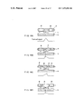
- FIGS. 6A through 6D illustrate a method of exposing a master to form phase pits, wherein FIG. 6A is a plan view of the a portion of the master, FIG. 6B illustrates an exposing light beam, FIG. 6C is a cross-sectional view at location 1 in FIG. 6A , and FIG. 6D is a cross-sectional view at location 2 in FIG. 6A ;
- FIG. 7 illustrates the spot diameters of two light beams and the spot distance therebetween
- FIG. 8 illustrates an optical system for exposing a master
- FIGS. 9A through 9F are process diagrams illustrating a stamper manufacturing process
- FIG. 10 is a perspective view, illustrating exposing a master (original board).
- FIG. 11A through 11C illustrate a background-art optical information recording medium, wherein FIG. 11A is a plan view of a portion of an optical information recording medium, FIG. 11B is a cross-sectional view at location 1 in FIG. 11A , and FIG. 11C is a cross-sectional view at location 2 in FIG. 11A ;
- FIGS. 12A and 12B illustrate a principle of reproducing (reading) a phase pits, wherein FIG. 12A is a plan view of a optical information recording medium and FIG. 12B is a waveform diagram of a push-pull signal;
- FIGS. 13A and 13B illustrate a principle of reproducing a phase pit with a tracking operation, wherein FIG. 13A is a plan view of optical information recording medium and FIG. 13B is a waveform diagram of a push-pull signal;
- FIGS. 14A and 14B illustrate a relationship between a phase pit and the waveform of a phase pit signal, wherein FIG. 14A is a plan view of an optical information recording medium and FIG. 14B is a waveform diagram of a push-pull signal;
- FIGS. 15A and 15B illustrate a case in which it is difficult to read (reproduce) a phase pit, wherein FIG. 15A is a plan view of an optical information recording medium and FIG. 15B is a waveform diagram of a push-pull signal;
- FIGS. 16A through 16D illustrate a distortion of the signal waveform from a phase pit caused by protruding of a recording mark
- FIGS. 17A through 17C illustrate an optical information recording medium which has been already proposed, wherein FIG. 17A is a plan view of the optical information recording medium, FIG. 17B is a cross-sectional view at location 1 in FIG. 17A , and FIG. 17C is a cross-sectional view at location 2 in FIG. 17A ; and
- FIGS. 18A and 18B illustrate a relationship between a phase pit and the waveform of a phase pit signal.
- a first feature of the disclosure herein relates to an optical information recording medium in which an information recording portion on a track is in the form of a groove and pre-format information is formed as phase pits, wherein a phase pit encoding preformat information for a groove has the same depth as the groove but is spaced radially from that groove and is connected, to an adjacent groove.
- a partition wall exists between a groove and the phase pit encoding preformat information for that groove. Therefore, the groove is not connected to its phase pit. Consequently, even if phase pits exist on the lands directly to the right and left of the groove, no significant cross-talk exists. In addition, owing to the effect of the partition wall, the phase pit signal is not degraded by information marks.
- a second feature relates to an optical information recording medium as described above, in which the width ⁇ of the partition wall in the radius direction of the track and the track pitch TP satisfy the relationship represented by the following inequality: ⁇ / TP ⁇ 0.1.
- the partition wall can eliminate or reduce deterioration of the phase pit signal in a recording operation.
- a third feature relates to an optical information recording medium as described above, in which the width Wp of a phase pit, the length Lp of said phase pit in the circular circumferential direction thereof, the track pitch TP, and the spot diameter BD of a recording/reproducing light beams satisfy the relationship represented by the following inequalities: Lp/BD ⁇ 1.0, and 0.8 ⁇ WP/TP ⁇ 0.9.
- the width Wp of a phase pit is thus set to a value allowing a sufficiently large signal amplitude for the phase pit, the phase signal can be reliably obtained and address information can be correctly reproduced.
- a fourth feature relates to an optical information recording medium as described above, in which the width Wp of a phase pit, the length Lp of the phase pit in the circular circumferential direction thereof, the track pitch TP, and the spot diameter BD of a recording/reproducing light beams satisfy the relationship represented by the following inequalities: 1.0 ⁇ Lp/BD , and 0.5 ⁇ WP/TP ⁇ 0.8.
- the phase pit signal can be obtained reliably and address information can be correctly reproduced.
- a fifth feature relates to an optical information recording medium as described above, in which the width Wp of a phase pit, the length Lp of the phase pit in the circular circumferential direction thereof, the track pitch TP, and the spot diameter BD of a recording/reproducing light beams satisfy the relationship represented by the following inequalities: 1.0 ⁇ Lp/BD , and 0.8 ⁇ WP/TP ⁇ 0.9.
- the width Wp of a phase pit and the length Lp thereof in the circular circumferential direction are thus set to values such that a sufficiently large signal amplitude can be taken for the phase pit, the phase pit signal can be obtained and reliably address information can be correctly reproduced.
- the width ⁇ of the partition wall in the radius direction can be adjusted so as to take an optional value in the mastering process.
- a seventh feature invention relates to a method of mastering a groove and a phase pit in connection with the sixth feature, in which both of the values of the spot diameters BD 1 and BD 2 of the first and second exposing light beams are respectively fixed to constant values, and in which the distance L between the spots of the first and second exposing light beams is adjusted by changing an incident angle of one or both exposing light beams directed to an object lens by use of a light deflection element.
- the reference symbol of the groove employed as the optical information recording track is G
- the land between the grooves G is L
- the phase pit representing pre-format information is P
- the groove width of the groove G is Wg
- that of the phase pit P is Wp.
- a phase pit P is not formed completely in the shape of ladder, but is formed shorter in the radial directory than the track pitch. In such way, the track center of the phase pit P is shifted by a distance s from that of a groove G. Namely, the structure of the present embodiment physically similar to that of the optical information recording medium of FIG. 17 , which has been already proposed.
- groove G of track 1 to be recorded and reproduced is not physically connected, in the radius direction, to phase pit 1 pertaining to track 1 . Instead, there exists a partition wall 1 and the phase pit 1 is formed such that the phase pit 1 is physically connected to the adjacent groove G of track 3 .
- groove G of track 1 to be recorded or reproduced is physically connected, in the radius direction, to phase pit 1 that encodes information for track 1 .
- the direction and meaning of the phase pit P in the radius direction of the present embodiments is reversed as compared to the proposed example of FIG. 18A .
- the peaks of the push-pull signal ( FIG. 2B ) generated from the phase pit P have the same polarity as in the proposed example shown in FIG. 18 .
- the polarity of a peak is determined by whether the phase pit P is at the right side or at the left side of the groove G. Therefore, even if there are radially aligned phase pits P at the right and left sides of a groove G, it is possible to detect the pre-format formed information encoded by those phase pits P.
- the partition wall 1 helps keep the recording mark M recorded on groove G of track 1 from spreading to the side of the phase pit 1 that encodes address information for track 1 , as shown in FIG. 3 .
- the recording mark M does not protrude to the side of the phase pit P as in the case of FIGS. 16B–16D .
- the recording mark can protrude into phase pit 1 .
- the diameter of the reproducing light beam is nearly equal to the track pitch TP, the recording mark portion protruding into the phase pit 1 at the time of reproducing track 1 is at the bottom portion of phase pit 1 , where the intensity of the reproducing light beam is at or close to zero.
- the partition wall 1 prevents deterioration of the phase pit signal and a reliable phase pit signal can be obtained. Thereby, address information can be correctly reproduced.
- FIGS. 2A and 2B showing the present embodiment, assuming that the amplitude of the phase pit 1 signal is B 1 and that of the phase pit 2 signed is B 2 , the relationship therebetween is as follows: B 1 ⁇ B 2 .
- the amplitude of the phase pit signal shown in FIG. 4 represents a numerical value standardized by dividing the value B 1 of the push-pull signal output shown in FIG. 2B by the addition (sum) signal Rf.
- the amplitude of the phase pit signal is less in the case of the present embodiment ( FIGS. 2A and 2B ) than in the proposed example ( FIGS. 18A and 18B ).
- the amplitude of the phase pit signal is lowered.
- the amplitude of the phase pit signal in FIG. 5 shows the standardized numerical value obtained by dividing the output value B 1 of the push-pull signal in FIG.
- a phase pit signal of high amplitude can be reliably obtained by setting Lp/BD ⁇ 1.0. Therefore, the problem of lowering of the phase pit signal amplitude can be alleviated. Furthermore, and replication mastering processes can be easier, and the manufacturing process yield for the optical information recording medium can be increased.
- the mastering method (method of exposing the original board) is improved by adjusting the width ⁇ of the partition wall 1 with high precision, as illustrated in FIGS. 6A–6D and FIG. 7 .
- cross section 1 is where groove G and the phase pit P exist
- cross section 2 is where only the groove G exists.
- the resist on the master is exposed by using, at the same time, two exposing light beam: an exposing light beam for the groove and an exposing light beam for the phase pit.
- the resist on the master is exposed by using only the exposing light beam for the groove.
- the width of the partition wall in the radius direction is ⁇
- the distance between the centers of the two exposing light beam spots is L
- the diameter of the light beam spot for the groove is BD 1
- that of the light beam spot for the phase pit is BD 2 (refer to FIG.
- the exposing optical system as shown in FIG. 8 is constructed such that the light beam emitted from a laser light source 3 is divided into the exposing light beam for the groove and exposing light beam for the phase pit by use of a polarization beam splitter 4 , and thereafter the exposing light beam for the groove is directed onto the resist firm 9 on a master 2 via a beam expander 5 , deflection prisms 6 and 7 , and an object lens 8 , while the exposing light beam for the phase pit is directed onto the resist film 9 of the master 2 via another beam expander 12 , deflection prisms 6 and 7 and another deflection prism 13 , and the object lens 8 after passing through a deflection prism 10 and a light modulator 11 .
- the diameter of the light beam is increased or decreased utilizing the element(s) such as the beam expanders 5 and 12 .
- the values of the spot diameters BD 1 and BD 2 of the two exposing light beams are fixed, and a light deflection element 14 is interposed in the optical path of one of the exposing light beams.
- the element 14 can be at the side of the exposing light beam for the groove, as shown in FIG. 8 , or element 14 can be at the side of the exposing high beam for the phase pit.
- the incident angle of the light beam to the object lens 8 can be changed and thereby the distance L between the spots can be adjusted.
- the width of the partition wall 1 can be adjusted simply and with high accuracy.
- the plastic substrate of such optical information recording medium is mass-reproduced (replicated) by the injection molding method using a metal mold called “stamper”.
- the stamper can be manufactured in accordance with the stamper manufacturing process (mastering) as shown in FIG. 9A-9F .
- a photo-resist film 9 is applied (painted) and baked on a glass base plate 15 .
- the resist master (original board) 2 is manufactured.
- a latent image is formed by exposing the resist master with the focused laser beam, e.g., an Ar laser 3 in FIG. 8 (Refer to the original board exposing process shown in FIG. 9B ).
- the exposed resist master 2 is developed, forming a groove pattern 16 in the photo resist firm 9 .
- a Ni-film is sputtered on the surface of the resist original board 2 having the groove pattern 16 formed in the photo resist film 9 and thereby an electrically conductive film 17 is formed thereon.
- Ni is laminated on the conductive film 17 and thereby the Ni electroforming plate 18 is formed thereon.
- the Ni electroforming plate 18 is completed as a stamper 19 through the processes of cleaning, rear surface polishing, inner and outer diameters processing (final processing), etc. (Refer to the processes of peeling off, cleaning, rear surface polishing, and final processing shown in FIG. 9F ).
- FIG. 10 A model of the master exposing process in FIG. 9B is shown in FIG. 10 .
- the master 2 is rotated by turntable 20 and transversely conveyed, and the laser beam of the Ar laser 4 is focused and radiated on the resist master 2 .
- the groove pattern 16 for the groove is formed as a spiral.
- the reference numeral 8 represents an object lens.
- respective exposing light beams for the groove and the phase pit are employed as illustrated in FIG. 8 .
- Those two exposing light beams are arranged so as to shift them in the radius direction as desired, and to keep them focused on the resist master 2 at the same time in order to expose the master.
- address information corresponding to the groove being exposed is recorded by the phase pit exposed at the same time.
- the exposing light beam for the groove is continuously radiated on the resist master 2 .
- the exposing light beam for the phase pit is intermittently radiated only on the parts of the master where the phase pits P are arranged. Namely, the exposing light beam for the phase pit is on-off controlled by light modulator 11 .
- the optical information recording medium as described in the example 2 was manufactured in an experiment and the medium thus manufactured was evaluated.
- the groove depth of the groove G and the phase pit P is set at about 600 A, the groove width Wg of the groove G about 0.3 ⁇ m, the groove width WP of the phase pit P about 0.5 ⁇ m, the length Lp of the phase pit P in the circular circumferential direction about 1 ⁇ m, the track pitch TP 0.74 ⁇ m, and the width ⁇ of the partition wall 1 in the radius direction about 0.2 ⁇ m.
- the wavelength of the semiconductor laser for use in recording/reproducing is set to 635 nm, the numerical aperture NA+0.60, and the diameter of the beam spot for use in recording/reproducing about 0.8 ⁇ m.
- the recording material for the optical information recording medium is a phase-change material (Ag In SbTe). Regarding such optical information recording medium, an intensity of about 0.2 is obtained as the amplitude of the phase pit signal. After the recording operation, it was confirmed that there exists no distortion in the waveform of the phase pit signal amplitude. Therefore, address information can be reliably reproduced.
- the groove depth of the groove G and the phase pit P is set to about 600 A, the groove width Wg of the groove G about 0.3 ⁇ m, the groove width Wp of the phase pit P about 0.65 ⁇ m, the length Lp of the phase pit P in the circular circumferential direction about 1 ⁇ m, the track pitch TP 0.74 ⁇ m, and the width ⁇ of the partition wall 1 in the radius direction about 0.1 ⁇ m.
- the spot diameter BD 1 of the exposing light beam for the groove and the spot diameter BD 2 of the exposing light beam for the phase pit are set to values (about 0.3 ⁇ m) approximately equal to each other, and the spot distance L between the exposing light beams is set to about 0.4 ⁇ m.
- the wavelength of the semiconductor laser for use in recording/reproducing is set to 635 nm
- the spot diameter of the light beam for use in recording/reproducing about 0.8 ⁇ m.
- the recording material for the optical information recording medium is a phase-variation material (Ag In Sb Te). Regarding such optical information recording medium, an intensity of about 0.35 is obtained as the amplitude of the phase pit signal. After the recording operation, it was confirmed that there exists no distortion in the waveform of the phase pit signal amplitude. Therefore, the address information can be stably reproduced.
- the first feature there exists a partition wall in the track between the a groove and a phase pit encoding information for the groove, and thereby the groove and the phase pit for it are not directly connected to each other. Consequently, even though there may be phase pits on the lands at the right and left sides of the groove, cross-talk is avoided. Furthermore, due to the effect of the partition wall, the phase pit signal after the recording operation does not deteriorate, and thereby a reliable phase pit signal can be obtained and address information can be correctly reproduced.
- the width ⁇ of the partition wall in the radius direction is set to a value that avoids undesirable effects of the spread of a recording mark, deterioration of the phase pit signal after the recording operation is avoided.
- the width Wp of the phase pit is set to a value enabling a sufficiently large amplitude of the phase pit signal, a reliable phase pit signal can be obtained and address information can be correctly reproduced.
- the length Lp of the phase pit in the circular circumferential direction is set to a value enabling a sufficiently large amplitude of the phase pit signal, a reliable phase pit signal can be obtained and address information can be correctly reproduced.
- the width Wp of the phase pit and the length Lp thereof in the circular circumferential direction are respectively set to values enabling sufficiently large amplitude of the phase pit signal, a reliable phase signal can be obtained and address information can be correctly reproduced.
- the mastering parameters can be determined by the calculation. Therefore, the width ⁇ of the partition wall in the radius direction can be adjusted to a desirable value.
- the adjustment of the width ⁇ of the partition walling the radius direction can be easily done with high precision.
Abstract
Description
Δ/TP≦0.1.
Lp/BD<1.0, and
0.8≦WP/TP≦0.9.
1.0≦Lp/BD, and
0.5≦WP/TP≦0.8.
1.0≦Lp/BD, and
0.8≦WP/TP≦0.9.
Δ=L−(
A1<A2.
B1<B2.
A1=B2, and
A2=B1.
A1>B1.
Lp/BD=0.5.
WP/TP=0.6˜0.9.
Δ=L−(BD1/2)+(BD2/2).
Claims (12)
Δ/TP<0.1.
Lp/BD<1.0, and
0.8≦WP/TP≦0.9.
1.0≦Lp/BD, and
0.5≦WP/TP≦0.8.
1.0≦Lp/BD, and
0.8≦WP/TP≦0.9.
Δ/TP≧0.1.
Lp/BD<1.0, and
0.8≦WP/TP≦0.9.
1.0≦Lp/BD, and
0.5≦WP/TP≦0.8.
1.0≦Lp/BD, and
0.8≦WP/TP≦0.9.
Δ=L−[(BD 1/2)+(BD 2/2)]; and
Priority Applications (2)
| Application Number | Priority Date | Filing Date | Title |
|---|---|---|---|
| US09/406,570 US7239602B2 (en) | 1998-08-27 | 1999-09-24 | Optical information recording medium with a partition wall between an information tracks groove and a preformat pit encoding information therefor |
| US11/247,695 US20060028975A1 (en) | 1997-08-27 | 2005-10-11 | Optical information recording medium and method of producing a master and stampers therefor |
Applications Claiming Priority (6)
| Application Number | Priority Date | Filing Date | Title |
|---|---|---|---|
| US09/140,975 US20020036978A1 (en) | 1997-08-27 | 1998-08-27 | Optical information recording medium and method of producing a master and stampers therefor |
| JP10-269723 | 1998-09-24 | ||
| JP26972398 | 1998-09-24 | ||
| JP28954798A JP3488643B2 (en) | 1998-09-24 | 1998-10-12 | Optical information recording medium and mastering method thereof |
| JP10-289547 | 1998-10-12 | ||
| US09/406,570 US7239602B2 (en) | 1998-08-27 | 1999-09-24 | Optical information recording medium with a partition wall between an information tracks groove and a preformat pit encoding information therefor |
Related Parent Applications (1)
| Application Number | Title | Priority Date | Filing Date |
|---|---|---|---|
| US09/140,975 Continuation-In-Part US20020036978A1 (en) | 1997-08-27 | 1998-08-27 | Optical information recording medium and method of producing a master and stampers therefor |
Related Child Applications (1)
| Application Number | Title | Priority Date | Filing Date |
|---|---|---|---|
| US11/247,695 Continuation US20060028975A1 (en) | 1997-08-27 | 2005-10-11 | Optical information recording medium and method of producing a master and stampers therefor |
Publications (2)
| Publication Number | Publication Date |
|---|---|
| US20020071380A1 US20020071380A1 (en) | 2002-06-13 |
| US7239602B2 true US7239602B2 (en) | 2007-07-03 |
Family
ID=27335747
Family Applications (2)
| Application Number | Title | Priority Date | Filing Date |
|---|---|---|---|
| US09/406,570 Expired - Fee Related US7239602B2 (en) | 1997-08-27 | 1999-09-24 | Optical information recording medium with a partition wall between an information tracks groove and a preformat pit encoding information therefor |
| US11/247,695 Abandoned US20060028975A1 (en) | 1997-08-27 | 2005-10-11 | Optical information recording medium and method of producing a master and stampers therefor |
Family Applications After (1)
| Application Number | Title | Priority Date | Filing Date |
|---|---|---|---|
| US11/247,695 Abandoned US20060028975A1 (en) | 1997-08-27 | 2005-10-11 | Optical information recording medium and method of producing a master and stampers therefor |
Country Status (1)
| Country | Link |
|---|---|
| US (2) | US7239602B2 (en) |
Families Citing this family (6)
| Publication number | Priority date | Publication date | Assignee | Title |
|---|---|---|---|---|
| DE60232125D1 (en) * | 2001-09-21 | 2009-06-10 | Ricoh Kk | Multi-level data processing for recording |
| TWI255452B (en) * | 2002-03-18 | 2006-05-21 | Ricoh Kk | Multi-level information recording apparatus, multi-level information recording method, multi-level information recording medium and multi-level information recording-reproducing apparatus |
| JP2003317256A (en) * | 2002-04-15 | 2003-11-07 | Ricoh Co Ltd | Multilevel data recording and reproducing device |
| US7190653B2 (en) * | 2002-10-21 | 2007-03-13 | Ricoh Company, Ltd. | Data recording/reproducing device |
| JP4027778B2 (en) * | 2002-10-30 | 2007-12-26 | 株式会社リコー | Multilevel data processing method and apparatus |
| JP4602648B2 (en) * | 2003-07-15 | 2010-12-22 | 株式会社リコー | Information recording method and information recording apparatus |
Citations (22)
| Publication number | Priority date | Publication date | Assignee | Title |
|---|---|---|---|---|
| US4423502A (en) * | 1981-01-12 | 1983-12-27 | U.S. Philips Corporation | Record carrier having an optically readable information structure |
| US4587648A (en) * | 1982-08-10 | 1986-05-06 | Tokyo Shibaura Denki Kabushiki Kaisha | Optical disk |
| US5448552A (en) * | 1992-09-29 | 1995-09-05 | Pioneer Electronic Corporation | Super resolution information reproduction by tracking address information in normal resolution |
| US5459712A (en) * | 1994-01-19 | 1995-10-17 | Kabushiki Kaisha Toshiba | Optical disk and optical disk apparatus where information is recorded having a specific track pitch and as a plurality of pit trains, each including a plurality of substantially trapezoidal pits |
| US5477527A (en) * | 1994-02-02 | 1995-12-19 | Sanyo Electric Co., Ltd. | High density optical disc and optical disc player |
| US5504734A (en) * | 1993-06-15 | 1996-04-02 | Nikon Corporation | Optical disc |
| US5602824A (en) * | 1994-08-12 | 1997-02-11 | Nikon Corporation | Optical disk capable of recording information on both land and groove tracks |
| US5638354A (en) * | 1993-07-16 | 1997-06-10 | Ricoh Company, Ltd. | Optical information recording medium |
| US5666345A (en) * | 1987-09-02 | 1997-09-09 | Sharp Kabushiki Kaisha | Optical memory medium with predetermined guide tracks and prepits |
| US5673250A (en) * | 1994-07-06 | 1997-09-30 | Sharp Kabushiki Kaisha | Optical recording medium having pit rows on every other boundary and reproducing method thereof |
| JPH09326138A (en) * | 1996-04-02 | 1997-12-16 | Sony Corp | Optical recording medium, method and device for recording/reproducing it |
| JPH1166630A (en) * | 1997-08-27 | 1999-03-09 | Ricoh Co Ltd | Exposing method for optical information recording medium and its master disk |
| US5883879A (en) * | 1996-05-28 | 1999-03-16 | Pioneer Video Corporation | High density optical disc configuration |
| US5892752A (en) * | 1995-10-09 | 1999-04-06 | Fujitsu Limited | Optical recording medium and reproducing method and apparatus having offset preformat data |
| US5926446A (en) * | 1996-03-12 | 1999-07-20 | Ricoh Company, Ltd. | Optical information recording medium and a method of tracking servo for optical information recording medium |
| US5933410A (en) * | 1996-06-26 | 1999-08-03 | Mitsubishi Denki Kabushiki Kaisha | Optical disc and optical disc driving apparatus |
| US5933411A (en) * | 1996-07-09 | 1999-08-03 | Sharp Kabushiki Kaisha | Optical recording medium having a wobbling section for recording address information and methods of recording and reproduction using same |
| US6055223A (en) * | 1984-10-02 | 2000-04-25 | Sharp Kabushiki Kaisha | Optical memory apparatus |
| US6118752A (en) * | 1995-07-07 | 2000-09-12 | Matsushita Electric Industrial Co., Ltd. | Optical information recording medium offset pre-pit array indicating identification information |
| US6128270A (en) * | 1996-09-26 | 2000-10-03 | Canon Kabushiki Kaisha | Optical information recording medium capable of recording information on both track guide grooves and lands and optical information reproducing apparatus for optical information recording medium |
| US6404729B1 (en) * | 1998-06-22 | 2002-06-11 | Pioneer Video Corporation | Optical disc |
| US20020075793A1 (en) * | 2000-09-12 | 2002-06-20 | Tdk Corporation | Optical recording medium |
Family Cites Families (15)
| Publication number | Priority date | Publication date | Assignee | Title |
|---|---|---|---|---|
| NL7810463A (en) * | 1978-10-19 | 1980-04-22 | Philips Nv | REGISTRATION HOLDER IN WHICH INFORMATION IS PRESENTED IN AN OPTICALLY READABLE INFORMATION STRUCTURE. |
| CA1165871A (en) * | 1978-11-08 | 1984-04-17 | Kornelis Bulthuis | Optically inscribable record carrier |
| NL7906576A (en) * | 1979-09-03 | 1981-03-05 | Philips Nv | REGISTRATION HOLDER IN WHICH INFORMATION HAS BEEN INCLUDED IN AN OPTICALLY READABLE INFORMATION STRUCTURE AND READING DEVICE THEREFOR. |
| NL8500153A (en) * | 1985-01-22 | 1986-08-18 | Philips Nv | REGISTRATION CARRIER INCLUDING A RELIEF STRUCTURE OF OPTICALLY DETECTABLE SERVOSCORE PARTS AND SECTOR ADDRESSES AND APPARATUS FOR APPLYING THIS STRUCTURE. |
| JPH0746429B2 (en) * | 1985-06-21 | 1995-05-17 | オリンパス光学工業株式会社 | Optical recording / reproducing device |
| JPH0721879B2 (en) * | 1987-11-07 | 1995-03-08 | 株式会社日立製作所 | Replica base for optical disc, stamper or master |
| US5517485A (en) * | 1993-02-26 | 1996-05-14 | Matsushita Electric Industrial Co., Ltd. | Optical information recording medium having first and second tracks and apparatus for recording to and reproducing from the medium |
| US5524734A (en) * | 1993-06-07 | 1996-06-11 | Shimano, Inc. | Brake apparatus for a bicycle which corrects braking force in a region of strong braking force |
| US5638345A (en) * | 1993-08-25 | 1997-06-10 | Canon Kabushiki Kaisha | Information recording and/or reproducing apparatus and method for use with a multi-track optical recording medium |
| JP3150850B2 (en) * | 1994-07-08 | 2001-03-26 | シャープ株式会社 | Manufacturing method of magneto-optical disk master |
| JP3081934B2 (en) * | 1995-08-17 | 2000-08-28 | 富士通株式会社 | Magneto-optical recording medium |
| US5946283A (en) * | 1996-04-10 | 1999-08-31 | Kabushiki Kaisha Toshiba | Optical information recording medium and optical information reproducing device |
| JP3091876B2 (en) * | 1996-08-30 | 2000-09-25 | 富士通株式会社 | Optical recording medium and drive device |
| KR100234291B1 (en) * | 1997-09-12 | 1999-12-15 | 윤종용 | Manufacturing method of master disc for making optical disc |
| KR100263878B1 (en) * | 1997-09-30 | 2000-08-16 | 윤종용 | Method of manufacturing master disk for making optical disk |
-
1999
- 1999-09-24 US US09/406,570 patent/US7239602B2/en not_active Expired - Fee Related
-
2005
- 2005-10-11 US US11/247,695 patent/US20060028975A1/en not_active Abandoned
Patent Citations (22)
| Publication number | Priority date | Publication date | Assignee | Title |
|---|---|---|---|---|
| US4423502A (en) * | 1981-01-12 | 1983-12-27 | U.S. Philips Corporation | Record carrier having an optically readable information structure |
| US4587648A (en) * | 1982-08-10 | 1986-05-06 | Tokyo Shibaura Denki Kabushiki Kaisha | Optical disk |
| US6055223A (en) * | 1984-10-02 | 2000-04-25 | Sharp Kabushiki Kaisha | Optical memory apparatus |
| US5666345A (en) * | 1987-09-02 | 1997-09-09 | Sharp Kabushiki Kaisha | Optical memory medium with predetermined guide tracks and prepits |
| US5448552A (en) * | 1992-09-29 | 1995-09-05 | Pioneer Electronic Corporation | Super resolution information reproduction by tracking address information in normal resolution |
| US5504734A (en) * | 1993-06-15 | 1996-04-02 | Nikon Corporation | Optical disc |
| US5638354A (en) * | 1993-07-16 | 1997-06-10 | Ricoh Company, Ltd. | Optical information recording medium |
| US5459712A (en) * | 1994-01-19 | 1995-10-17 | Kabushiki Kaisha Toshiba | Optical disk and optical disk apparatus where information is recorded having a specific track pitch and as a plurality of pit trains, each including a plurality of substantially trapezoidal pits |
| US5477527A (en) * | 1994-02-02 | 1995-12-19 | Sanyo Electric Co., Ltd. | High density optical disc and optical disc player |
| US5673250A (en) * | 1994-07-06 | 1997-09-30 | Sharp Kabushiki Kaisha | Optical recording medium having pit rows on every other boundary and reproducing method thereof |
| US5602824A (en) * | 1994-08-12 | 1997-02-11 | Nikon Corporation | Optical disk capable of recording information on both land and groove tracks |
| US6118752A (en) * | 1995-07-07 | 2000-09-12 | Matsushita Electric Industrial Co., Ltd. | Optical information recording medium offset pre-pit array indicating identification information |
| US5892752A (en) * | 1995-10-09 | 1999-04-06 | Fujitsu Limited | Optical recording medium and reproducing method and apparatus having offset preformat data |
| US5926446A (en) * | 1996-03-12 | 1999-07-20 | Ricoh Company, Ltd. | Optical information recording medium and a method of tracking servo for optical information recording medium |
| JPH09326138A (en) * | 1996-04-02 | 1997-12-16 | Sony Corp | Optical recording medium, method and device for recording/reproducing it |
| US5883879A (en) * | 1996-05-28 | 1999-03-16 | Pioneer Video Corporation | High density optical disc configuration |
| US5933410A (en) * | 1996-06-26 | 1999-08-03 | Mitsubishi Denki Kabushiki Kaisha | Optical disc and optical disc driving apparatus |
| US5933411A (en) * | 1996-07-09 | 1999-08-03 | Sharp Kabushiki Kaisha | Optical recording medium having a wobbling section for recording address information and methods of recording and reproduction using same |
| US6128270A (en) * | 1996-09-26 | 2000-10-03 | Canon Kabushiki Kaisha | Optical information recording medium capable of recording information on both track guide grooves and lands and optical information reproducing apparatus for optical information recording medium |
| JPH1166630A (en) * | 1997-08-27 | 1999-03-09 | Ricoh Co Ltd | Exposing method for optical information recording medium and its master disk |
| US6404729B1 (en) * | 1998-06-22 | 2002-06-11 | Pioneer Video Corporation | Optical disc |
| US20020075793A1 (en) * | 2000-09-12 | 2002-06-20 | Tdk Corporation | Optical recording medium |
Non-Patent Citations (2)
| Title |
|---|
| Abstract of JP 09/230696 published May 9, 1997. * |
| MAT (Machine assisted translation) of JP 11-066630. * |
Also Published As
| Publication number | Publication date |
|---|---|
| US20020071380A1 (en) | 2002-06-13 |
| US20060028975A1 (en) | 2006-02-09 |
Similar Documents
| Publication | Publication Date | Title |
|---|---|---|
| US6295271B1 (en) | Optical recording medium having tracks, each track having a plurality of wobble sections/one-side wobble regions | |
| US5602823A (en) | Optical recording medium having pre-formatted patterns arrange by shifting phases | |
| US6226257B1 (en) | Optical information storage medium having lands and grooves both serving as recording tracks | |
| KR19980080909A (en) | Method for forming optical disc for information recording reproduction and optical disc for information recording reproduction | |
| EP1429321A1 (en) | Optical recording/reproducing medium-use substrate, production method for optical recording/reproducing medium producing stamper and optical recording/reprodcing medium producing stamper | |
| US7239602B2 (en) | Optical information recording medium with a partition wall between an information tracks groove and a preformat pit encoding information therefor | |
| JP2003346348A (en) | Optical disk and its recording and reproducing method | |
| US6404729B1 (en) | Optical disc | |
| JP3209948B2 (en) | Optical information recording medium and master disc exposure method | |
| JP2000187887A (en) | Optical disk | |
| US6136402A (en) | Optical recording medium having disconnected lands and grooves forming control signal portion | |
| JP3729268B2 (en) | Preformat information detection method | |
| WO2004081928A1 (en) | Optical disk | |
| JP2001209945A (en) | Optical disk and recording and reproducing device | |
| JP2776230B2 (en) | optical disk | |
| JP3488643B2 (en) | Optical information recording medium and mastering method thereof | |
| JP3782077B2 (en) | Optical disc and recording / reproducing apparatus | |
| JP4106841B2 (en) | Optical recording medium and manufacturing method thereof | |
| JPH03104021A (en) | Optical recording medium and recording and reproducing method thereof | |
| JP2002260239A (en) | Optical disk and optical original disk exposing device | |
| TWI289836B (en) | Information recording medium, information recording/reproducing method, and information recording/reproducing device | |
| JP3220091B2 (en) | Optical recording medium | |
| JP2002279697A (en) | Method for manufacturing optical disk substrate and optical master disk | |
| JP2001167447A (en) | Writable optical disk | |
| JP2004030917A (en) | Optical disk and recording/reproducing device |
Legal Events
| Date | Code | Title | Description |
|---|---|---|---|
| AS | Assignment |
Owner name: RICOH COMPANY, LTD., JAPAN Free format text: ASSIGNMENT OF ASSIGNORS INTEREST;ASSIGNORS:SHIMIZU, AKIHIKO;YOKOI, KENYA;REEL/FRAME:010462/0820;SIGNING DATES FROM 19991210 TO 19991213 |
|
| AS | Assignment |
Owner name: RICOH COMPANY, LTD., JAPAN Free format text: CORRECTIVE ASSIGNMENT TO CORRECT THE ASSIGNEE'S ADDRESS PREVIOUSLY REORDED AT REEL 010462 FRAME 0820;ASSIGNORS:SHIMIZU, AKIHIKO;YOKOI, KENYA;REEL/FRAME:017209/0433;SIGNING DATES FROM 19991210 TO 19991213 |
|
| STCF | Information on status: patent grant |
Free format text: PATENTED CASE |
|
| FEPP | Fee payment procedure |
Free format text: PAYOR NUMBER ASSIGNED (ORIGINAL EVENT CODE: ASPN); ENTITY STATUS OF PATENT OWNER: LARGE ENTITY |
|
| FPAY | Fee payment |
Year of fee payment: 4 |
|
| FPAY | Fee payment |
Year of fee payment: 8 |
|
| FEPP | Fee payment procedure |
Free format text: MAINTENANCE FEE REMINDER MAILED (ORIGINAL EVENT CODE: REM.); ENTITY STATUS OF PATENT OWNER: LARGE ENTITY |
|
| LAPS | Lapse for failure to pay maintenance fees |
Free format text: PATENT EXPIRED FOR FAILURE TO PAY MAINTENANCE FEES (ORIGINAL EVENT CODE: EXP.); ENTITY STATUS OF PATENT OWNER: LARGE ENTITY |
|
| STCH | Information on status: patent discontinuation |
Free format text: PATENT EXPIRED DUE TO NONPAYMENT OF MAINTENANCE FEES UNDER 37 CFR 1.362 |
|
| FP | Lapsed due to failure to pay maintenance fee |
Effective date: 20190703 |