US7240927B2 - Connection assembly used for connection between a fuel nozzle and a filling hose - Google Patents
Connection assembly used for connection between a fuel nozzle and a filling hose Download PDFInfo
- Publication number
- US7240927B2 US7240927B2 US11/144,820 US14482005A US7240927B2 US 7240927 B2 US7240927 B2 US 7240927B2 US 14482005 A US14482005 A US 14482005A US 7240927 B2 US7240927 B2 US 7240927B2
- Authority
- US
- United States
- Prior art keywords
- claws
- engaging ring
- annular groove
- female connector
- male connector
- Prior art date
- Legal status (The legal status is an assumption and is not a legal conclusion. Google has not performed a legal analysis and makes no representation as to the accuracy of the status listed.)
- Expired - Fee Related, expires
Links
Images


Classifications
-
- F—MECHANICAL ENGINEERING; LIGHTING; HEATING; WEAPONS; BLASTING
- F16—ENGINEERING ELEMENTS AND UNITS; GENERAL MEASURES FOR PRODUCING AND MAINTAINING EFFECTIVE FUNCTIONING OF MACHINES OR INSTALLATIONS; THERMAL INSULATION IN GENERAL
- F16L—PIPES; JOINTS OR FITTINGS FOR PIPES; SUPPORTS FOR PIPES, CABLES OR PROTECTIVE TUBING; MEANS FOR THERMAL INSULATION IN GENERAL
- F16L37/00—Couplings of the quick-acting type
- F16L37/08—Couplings of the quick-acting type in which the connection between abutting or axially overlapping ends is maintained by locking members
- F16L37/084—Couplings of the quick-acting type in which the connection between abutting or axially overlapping ends is maintained by locking members combined with automatic locking
- F16L37/091—Couplings of the quick-acting type in which the connection between abutting or axially overlapping ends is maintained by locking members combined with automatic locking by means of a ring provided with teeth or fingers
-
- F—MECHANICAL ENGINEERING; LIGHTING; HEATING; WEAPONS; BLASTING
- F16—ENGINEERING ELEMENTS AND UNITS; GENERAL MEASURES FOR PRODUCING AND MAINTAINING EFFECTIVE FUNCTIONING OF MACHINES OR INSTALLATIONS; THERMAL INSULATION IN GENERAL
- F16L—PIPES; JOINTS OR FITTINGS FOR PIPES; SUPPORTS FOR PIPES, CABLES OR PROTECTIVE TUBING; MEANS FOR THERMAL INSULATION IN GENERAL
- F16L37/00—Couplings of the quick-acting type
- F16L37/24—Couplings of the quick-acting type in which the connection is made by inserting one member axially into the other and rotating it to a limited extent, e.g. with bayonet action
- F16L37/244—Couplings of the quick-acting type in which the connection is made by inserting one member axially into the other and rotating it to a limited extent, e.g. with bayonet action the coupling being co-axial with the pipe
- F16L37/252—Couplings of the quick-acting type in which the connection is made by inserting one member axially into the other and rotating it to a limited extent, e.g. with bayonet action the coupling being co-axial with the pipe the male part having lugs on its periphery penetrating in the corresponding slots provided in the female part
-
- Y—GENERAL TAGGING OF NEW TECHNOLOGICAL DEVELOPMENTS; GENERAL TAGGING OF CROSS-SECTIONAL TECHNOLOGIES SPANNING OVER SEVERAL SECTIONS OF THE IPC; TECHNICAL SUBJECTS COVERED BY FORMER USPC CROSS-REFERENCE ART COLLECTIONS [XRACs] AND DIGESTS
- Y10—TECHNICAL SUBJECTS COVERED BY FORMER USPC
- Y10S—TECHNICAL SUBJECTS COVERED BY FORMER USPC CROSS-REFERENCE ART COLLECTIONS [XRACs] AND DIGESTS
- Y10S285/00—Pipe joints or couplings
- Y10S285/921—Snap-fit
Definitions
- the present invention relates to a connection assembly, and more particularly to a connection assembly used for connection between a fuel nozzle and a filling hose to facilitate separation between the fuel nozzle and the filling hose when the fuel nozzle encounters a pulling force so as to avoid hazard caused by the breakage of the filling hose.
- U.S. Pat. No. 5,346,260 discloses a conventional coupling member for connecting a fuel nozzle to a filling hose.
- the coupling member is composed of a male coupling member and a female coupling member.
- the coupling member is able to facilitate the separation between the male coupling member and the female coupling member to prevent the entrainment of the nozzle by the vehicle from rupturing the hose or damaging the fuel pump having a detent which is wedged out of engagement by a torque applied to the male member within the female member against the force of a restoring spring because of play between the male and female coupling members.
- the structure disclosed in the '260 patent does have the function and ability to facilitate the separation between the fuel nozzle and the filing hose, however because the engagement between the male coupling member and the female coupling member depends solely on the detent ring and the restoring spring, it is quite easy for the filling hose and the fuel nozzle to separate when the vehicle is applying a force to the fuel nozzle, which causes a lot of unnecessary trouble in fixing the separated fuel nozzle and the filling hose.
- the present invention tends to provide an improved connection assembly to mitigate the aforementioned problems.
- the primary objective of the present invention is to provide a connection assembly having a male connector and a female connector.
- the male connector further has a first engaging ring mounted around the male connector and the female connector has a second engaging ring received inside the female connector such that when the male connector is partially received in the female connector, the first engaging ring is able to securely engage with an inner periphery of the female connector and the second engaging ring is able to engage with an outer periphery of the male connector so as to accomplish the connection between the male connector and the female connector.
- the male connector has a first annular groove defined in the outer periphery of the male connector to correspond to the second engaging ring and the female connector has a second annular groove defined in the inner periphery of the female connector.
- the first engaging ring has multiple first claws extending outward to correspond to a periphery defining the second annular groove and the second engaging ring has multiple second claws extending inward to correspond to a periphery defining the first annular groove so as to allow the first claws to engage with the periphery defining the second annular groove and the second claws to engage with the periphery defining the first annular groove.
- a further aspect of the present invention is that an engagement strength of the first claws to the periphery defining the second annular groove is dependent from a width of the first claws, and an engagement strength of the second claws to the periphery defining the first annular groove is dependent from a width of the second claws.
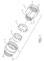
- FIG. 1 is an exploded perspective view showing the components of the connection assembly of the present invention
- FIG. 2A is a perspective view of the first engaging ring
- FIG. 2B is a partially cross sectional perspective view of the first engaging ring
- FIG. 3A is a perspective view of the second engaging ring
- FIG. 3B is a partially cross sectional perspective view of the second engaging ring.
- FIG. 4 is a cross sectional view showing the engagement of the male connector and the female connector.
- the connector assembly in accordance with the present invention includes a male connector ( 1 ) and a female connector ( 3 ). Furthermore, a first engaging ring ( 2 ) is to be mounted around the male connector ( 1 ) and a second engaging ring ( 4 ) is to be mounted inside the female connector ( 3 ).
- the male connector ( 1 ) has a bore ( 11 ) defined through the male connector ( 1 ), an inner threading ( 12 ) formed on an inner periphery defining the bore ( 11 ) for connection with a filling hose (not shown) and a hollow extension ( 13 ) extending out of the male connector ( 1 ) and having two open ends, an outer annular sidewall and a first annular groove ( 131 ) defined in an outer periphery of the extension ( 13 ).
- the extension ( 13 ) of the male connector ( 1 ) may further have an outer annular lip ( 133 ) radially extending outward from the outer annular sidewall of the extension ( 13 ).
- the first engaging ring ( 2 ) has a diameter slightly larger than a diameter of the extension ( 13 ) so that the first engaging ring ( 2 ) is able to be securely mounted around the extension ( 13 ).
- the female connector ( 3 ) has a passage ( 31 ) defined through the female connector ( 3 ), a hollow skirt ( 32 ) extending out of the female connector ( 3 ) and having two open ends, an outer threading ( 321 ) formed on an outer periphery of the skirt ( 32 ) for connection with a fuel nozzle (not shown) and a second annular groove ( 33 ) defined in an inner periphery of the female connector ( 3 ) defining the passage ( 31 ).
- the female connector ( 3 ) may further have an inner annular lip ( 34 ). The inner annular lip ( 34 ) extends inward from the inner periphery of the female connector ( 3 ).
- the first engaging ring ( 2 ) has an inner annular sidewall, is provided with multiple legs ( 21 ) extending from a peripheral edge of the first engaging ring ( 2 ) and first claws ( 22 ) intermittently or alternately extending outward from a distal end of each of the legs ( 21 ).
- the first engaging ring ( 2 ) may further have multiple inner hooks ( 23 ).
- the inner hooks ( 23 ) extend inward from the inner annular sidewall and hook outer annular lip ( 133 ) on the extension ( 13 ) of the male connector ( 1 ) to securely mount the first engaging ring ( 2 ) around the male connector ( 1 ).
- the second engaging ring ( 4 ) has an outer annular sidewall, is provided with multiple fingers ( 41 ) extending upward from a peripheral edge of the second engaging ring ( 4 ) and second claws ( 42 ) intermittently or alternately extending inward from a distal end of each of the fingers ( 41 ).
- the second engaging ring ( 4 ) may further have multiple outer hooks ( 43 ).
- the outer hooks ( 43 ) extend outward from the outer annular sidewall of the second engaging ring ( 4 ) and hook annular inner lip ( 34 ) on the inner periphery of the female connector ( 3 ) to securely connect the female connector ( 3 ) to the male connector ( 1 ).
- the first engaging ring ( 2 ) is securely mounted around the extension ( 13 ) and the second engaging ring ( 4 ) is securely received in the passage ( 31 ) of the female connector ( 3 ). Thereafter, the extension ( 13 ) with the first engaging ring ( 2 ) mounted thereon is inserted into the passage ( 31 ) of the female connector ( 3 ). It is to be noted that the first engaging ring ( 2 ) has a diameter larger than that of the second engaging ring ( 4 ) such that the second engaging ring ( 4 ) is able to be inserted into the first engaging ring ( 2 ).
- first claws ( 22 ) extending outward and the second claws ( 42 ) extending inward, after the extension ( 13 ) of the male connector ( 1 ) is inserted into the passage ( 31 ) of the female connector ( 3 ), the first claws ( 22 ) are able to abut a bottom face defining the second annular groove ( 33 ) and the second claws ( 42 ) are able to abut a bottom face defining the first annular groove ( 131 ).
Abstract
A connection assembly has a male connector, a first engaging ring securely mounted on the male connector, a female connector and a second engaging ring securely received in the female connector. The first engaging ring has first claws formed to abut a periphery defining the second annular groove formed on the female connector and the second engaging ring has second claws formed to abut a periphery defining the first annular groove formed on the male connector. Engagement between the male connector and the female connector is accomplished after the abutment between the first claws and the second annular groove and between the second claws and the first annular groove is finished.
Description
1. Field of the Invention
The present invention relates to a connection assembly, and more particularly to a connection assembly used for connection between a fuel nozzle and a filling hose to facilitate separation between the fuel nozzle and the filling hose when the fuel nozzle encounters a pulling force so as to avoid hazard caused by the breakage of the filling hose.
2. Description of Related Art
U.S. Pat. No. 5,346,260 ('260) discloses a conventional coupling member for connecting a fuel nozzle to a filling hose. The coupling member is composed of a male coupling member and a female coupling member. The coupling member is able to facilitate the separation between the male coupling member and the female coupling member to prevent the entrainment of the nozzle by the vehicle from rupturing the hose or damaging the fuel pump having a detent which is wedged out of engagement by a torque applied to the male member within the female member against the force of a restoring spring because of play between the male and female coupling members.
The structure disclosed in the '260 patent does have the function and ability to facilitate the separation between the fuel nozzle and the filing hose, however because the engagement between the male coupling member and the female coupling member depends solely on the detent ring and the restoring spring, it is quite easy for the filling hose and the fuel nozzle to separate when the vehicle is applying a force to the fuel nozzle, which causes a lot of unnecessary trouble in fixing the separated fuel nozzle and the filling hose.
To overcome the shortcomings, the present invention tends to provide an improved connection assembly to mitigate the aforementioned problems.
The primary objective of the present invention is to provide a connection assembly having a male connector and a female connector. The male connector further has a first engaging ring mounted around the male connector and the female connector has a second engaging ring received inside the female connector such that when the male connector is partially received in the female connector, the first engaging ring is able to securely engage with an inner periphery of the female connector and the second engaging ring is able to engage with an outer periphery of the male connector so as to accomplish the connection between the male connector and the female connector. Whereby when the fuel nozzle experiences a rupturing force, due to the material for both the first engaging ring and the second engaging ring being resilient plastic, separation between the fuel nozzle and the filing hose is certain only when the rupturing force reaches a specified level.
In one aspect of the present invention, the male connector has a first annular groove defined in the outer periphery of the male connector to correspond to the second engaging ring and the female connector has a second annular groove defined in the inner periphery of the female connector.
In yet another aspect of the present invention, the first engaging ring has multiple first claws extending outward to correspond to a periphery defining the second annular groove and the second engaging ring has multiple second claws extending inward to correspond to a periphery defining the first annular groove so as to allow the first claws to engage with the periphery defining the second annular groove and the second claws to engage with the periphery defining the first annular groove.
A further aspect of the present invention is that an engagement strength of the first claws to the periphery defining the second annular groove is dependent from a width of the first claws, and an engagement strength of the second claws to the periphery defining the first annular groove is dependent from a width of the second claws.
Other objects, advantages and novel features of the invention will become more apparent from the following detailed description when taken in conjunction with the accompanying drawings.
With reference to FIG. 1 , it is noted that the connector assembly in accordance with the present invention includes a male connector (1) and a female connector (3). Furthermore, a first engaging ring (2) is to be mounted around the male connector (1) and a second engaging ring (4) is to be mounted inside the female connector (3).
The male connector (1) has a bore (11) defined through the male connector (1), an inner threading (12) formed on an inner periphery defining the bore (11) for connection with a filling hose (not shown) and a hollow extension (13) extending out of the male connector (1) and having two open ends, an outer annular sidewall and a first annular groove (131) defined in an outer periphery of the extension (13). The extension (13) of the male connector (1) may further have an outer annular lip (133) radially extending outward from the outer annular sidewall of the extension (13).
The first engaging ring (2) has a diameter slightly larger than a diameter of the extension (13) so that the first engaging ring (2) is able to be securely mounted around the extension (13).
The female connector (3) has a passage (31) defined through the female connector (3), a hollow skirt (32) extending out of the female connector (3) and having two open ends, an outer threading (321) formed on an outer periphery of the skirt (32) for connection with a fuel nozzle (not shown) and a second annular groove (33) defined in an inner periphery of the female connector (3) defining the passage (31). The female connector (3) may further have an inner annular lip (34). The inner annular lip (34) extends inward from the inner periphery of the female connector (3).
With reference to FIGS. 2A and 2B , it is noted that the first engaging ring (2) has an inner annular sidewall, is provided with multiple legs (21) extending from a peripheral edge of the first engaging ring (2) and first claws (22) intermittently or alternately extending outward from a distal end of each of the legs (21). The first engaging ring (2) may further have multiple inner hooks (23). The inner hooks (23) extend inward from the inner annular sidewall and hook outer annular lip (133) on the extension (13) of the male connector (1) to securely mount the first engaging ring (2) around the male connector (1).
With reference to FIGS. 3A and 3B , it is noted that the second engaging ring (4) has an outer annular sidewall, is provided with multiple fingers (41) extending upward from a peripheral edge of the second engaging ring (4) and second claws (42) intermittently or alternately extending inward from a distal end of each of the fingers (41). The second engaging ring (4) may further have multiple outer hooks (43). The outer hooks (43) extend outward from the outer annular sidewall of the second engaging ring (4) and hook annular inner lip (34) on the inner periphery of the female connector (3) to securely connect the female connector (3) to the male connector (1).
With reference to FIG. 4 , it is noted that when the connection assembly of the present invention is combined, the first engaging ring (2) is securely mounted around the extension (13) and the second engaging ring (4) is securely received in the passage (31) of the female connector (3). Thereafter, the extension (13) with the first engaging ring (2) mounted thereon is inserted into the passage (31) of the female connector (3). It is to be noted that the first engaging ring (2) has a diameter larger than that of the second engaging ring (4) such that the second engaging ring (4) is able to be inserted into the first engaging ring (2). Further, due to the first claws (22) extending outward and the second claws (42) extending inward, after the extension (13) of the male connector (1) is inserted into the passage (31) of the female connector (3), the first claws (22) are able to abut a bottom face defining the second annular groove (33) and the second claws (42) are able to abut a bottom face defining the first annular groove (131). From the mutual abutment between the first claws (22) and the second annular groove (33) and between the second claws (42) and the first annular groove (131), the engagement between the male connector (1) and the female connector (3) is secured. However, due to the material for both the first engaging ring (2) and the second engaging ring (4) being a resilient plastic, when a rupturing force is applied to the fuel nozzle, the female connector (3) will be separated from the male connector (1) after the engaging force from the first claws (22) to the second annular groove (33) and the second claws (42) to the first annular groove (131) is overcome.
It is to be understood, however, that even though numerous characteristics and advantages of the present invention have been set forth in the foregoing description, together with details of the structure and function of the invention, the disclosure is illustrative only, and changes may be made in detail, especially in matters of shape, size, and arrangement of parts within the principles of the invention to the full extent indicated by the broad general meaning of the terms in which the appended claims are expressed.
Claims (8)
1. A connection assembly for connecting a filling hose to a fuel nozzle, the connection assembly comprising:
a male connector having a bore defined through the male connector, an inner threading formed inside the bore for connection with the filing hose, a hollow extension and having two open ends, an outer annular sidewall and a first annular groove defined in an outer periphery of the extension;
a first engaging ring mounted on the extension and having an inner annular sidewall, multiple legs extending from a peripheral edge of the first engaging ring and multiple first claws extending outward from distal ends of the legs;
a female connector having a passage defined through the female connector to correspond to and receive therein the extension of the male connector, a second annular groove defined in an inner periphery of the female connector defining the passage to correspond to the first claws so as to allow the first claws to abut a bottom face defining the second annular groove, a hollow skirt extending from an end opposite the male connector and an outer threading formed on an outer periphery of the skirt for connection with the fuel nozzle; and
a second engaging ring securely received in the passage of the female connector and having an outer annular sidewall, multiple fingers extending from a peripheral edge of the second engaging ring and multiple second claws extending inward from distal ends of the fingers to correspond to and abut a bottom face defining the first annular groove such that abutment of the first claws to the second annular groove and of the second claws to the first annular groove secures engagement between the male connector and the female connector.
2. The connection assembly as claimed in claim 1 , wherein the first claws are alternately formed with respect to the legs.
3. The connection assembly as claimed in claim 2 , wherein the second claws are alternately formed with respect to the fingers.
4. The connection assembly as claimed in claim 1 , wherein the first engaging ring has a diameter larger than that of the second engaging ring such that after the extension of the male connector is inserted into the passage of the female connector, the first claws are able to abut the second annular groove and the second claws are able to abut the first annular groove.
5. The connection assembly as claimed in claim 2 , wherein the first engaging ring has a diameter larger than that of the second engaging ring such that after the extension of the male connector is inserted into the passage of the female connector, the first claws are able to abut the second annular groove and the second claws are able to abut the first annular groove.
6. The connection assembly as claimed in claim 3 , wherein the first engaging ring has a diameter larger than that of the second engaging ring such that after the extension of the male connector is inserted into the passage of the female connector, the first claws are able to abut the second annular groove and the second claws are able to abut the first annular groove.
7. The connection assembly as claimed in claim 6 , wherein an engagement strength of the first claws to the periphery defining the second annular groove is dependent from a width of the first claws, and an engagement strength of the second claws to the periphery defining the first annular groove is dependent from a width of the second claws.
8. The connection assembly as claimed in claim 7 , wherein the extension of the male connector further has an outer annular lip radially extending outward from the outer annular sidewall of the extension;
the female connector further has an inner annular lip extending inward from the inner periphery of the female connector;
the first engaging ring further has multiple inner hooks extending inward from the inner annular sidewall and hooking the outer annular lip on the extension of the male connector to securely mount the first engaging ring around the male connector; and
the second engaging ring further has multiple outer hooks extending outward from the outer annular sidewall of the second engaging ring and hooking the annular inner lip on the inner periphery of the female connector to securely connect the female connector to the male connector.
Priority Applications (1)
| Application Number | Priority Date | Filing Date | Title |
|---|---|---|---|
| US11/144,820 US7240927B2 (en) | 2005-06-06 | 2005-06-06 | Connection assembly used for connection between a fuel nozzle and a filling hose |
Applications Claiming Priority (1)
| Application Number | Priority Date | Filing Date | Title |
|---|---|---|---|
| US11/144,820 US7240927B2 (en) | 2005-06-06 | 2005-06-06 | Connection assembly used for connection between a fuel nozzle and a filling hose |
Publications (2)
| Publication Number | Publication Date |
|---|---|
| US20070001449A1 US20070001449A1 (en) | 2007-01-04 |
| US7240927B2 true US7240927B2 (en) | 2007-07-10 |
Family
ID=37588548
Family Applications (1)
| Application Number | Title | Priority Date | Filing Date |
|---|---|---|---|
| US11/144,820 Expired - Fee Related US7240927B2 (en) | 2005-06-06 | 2005-06-06 | Connection assembly used for connection between a fuel nozzle and a filling hose |
Country Status (1)
| Country | Link |
|---|---|
| US (1) | US7240927B2 (en) |
Cited By (11)
| Publication number | Priority date | Publication date | Assignee | Title |
|---|---|---|---|---|
| US20060033331A1 (en) * | 2004-08-11 | 2006-02-16 | Smiths Medical Asd, Inc. | Medical coupling system |
| USD669558S1 (en) * | 2011-06-13 | 2012-10-23 | Fluidmaster, Inc. | Fluid connector |
| US8870238B2 (en) | 2011-06-27 | 2014-10-28 | Smiths Medical Asd, Inc. | Fitting for medicament infusion systems |
| US20150276107A1 (en) * | 2012-07-25 | 2015-10-01 | Hamilton Bonaduz Ag | Coupling formation of a pipetting channel of a pipetting device for coupling of a pipette tip thereto |
| USD744821S1 (en) * | 2015-04-23 | 2015-12-08 | Security Locknut LLC | Hex locknut |
| USD746129S1 (en) * | 2015-03-02 | 2015-12-29 | Kyo-Ei Industrial Corporation | Nut for mounting wheel |
| US9220833B2 (en) | 2011-06-27 | 2015-12-29 | Smiths Medical Asd, Inc. | Medicament infusion systems |
| US9364651B2 (en) | 2010-02-23 | 2016-06-14 | Smiths Medical Asd, Inc. | Adapter with special fitting |
| US9604838B2 (en) | 2015-02-09 | 2017-03-28 | Veeder-Root Company | Breakaway coupling monitoring |
| US20190056183A1 (en) * | 2017-08-15 | 2019-02-21 | Champ Tech Optical (Foshan) Corporation | Fixing structure and heat dissipation device therewith |
| US10737087B2 (en) | 2012-04-17 | 2020-08-11 | Smiths Medical Asd, Inc. | Filling fitting |
Families Citing this family (1)
| Publication number | Priority date | Publication date | Assignee | Title |
|---|---|---|---|---|
| AT515986B1 (en) * | 2014-07-07 | 2016-03-15 | E Hawle Armaturenwerke Gmbh | connector |
Citations (6)
| Publication number | Priority date | Publication date | Assignee | Title |
|---|---|---|---|---|
| US5178424A (en) * | 1991-07-01 | 1993-01-12 | Itt Corporation | Pop-off quick connect indicator |
| US5346260A (en) * | 1992-02-01 | 1994-09-13 | Albert Hiby Gmbh & Co. Kg | Device for connecting a fuel nozzle to a filling hose |
| USRE36630E (en) * | 1992-01-17 | 2000-03-28 | Senior Engineering Investments Ag | Thermal isolation coupling system |
| US6241292B1 (en) * | 1999-01-12 | 2001-06-05 | Yang Che-Hsiung | Coupling device for metal pipes with innovative packing structure |
| US20020070550A1 (en) * | 2000-12-12 | 2002-06-13 | Michael Lin | Rotation connector |
| US6851728B2 (en) * | 2002-07-10 | 2005-02-08 | Hakko Metal Industries Ltd. | Pipe-coupling device |
-
2005
- 2005-06-06 US US11/144,820 patent/US7240927B2/en not_active Expired - Fee Related
Patent Citations (6)
| Publication number | Priority date | Publication date | Assignee | Title |
|---|---|---|---|---|
| US5178424A (en) * | 1991-07-01 | 1993-01-12 | Itt Corporation | Pop-off quick connect indicator |
| USRE36630E (en) * | 1992-01-17 | 2000-03-28 | Senior Engineering Investments Ag | Thermal isolation coupling system |
| US5346260A (en) * | 1992-02-01 | 1994-09-13 | Albert Hiby Gmbh & Co. Kg | Device for connecting a fuel nozzle to a filling hose |
| US6241292B1 (en) * | 1999-01-12 | 2001-06-05 | Yang Che-Hsiung | Coupling device for metal pipes with innovative packing structure |
| US20020070550A1 (en) * | 2000-12-12 | 2002-06-13 | Michael Lin | Rotation connector |
| US6851728B2 (en) * | 2002-07-10 | 2005-02-08 | Hakko Metal Industries Ltd. | Pipe-coupling device |
Cited By (17)
| Publication number | Priority date | Publication date | Assignee | Title |
|---|---|---|---|---|
| US7497484B2 (en) * | 2004-08-11 | 2009-03-03 | Smiths Medical Asd, Inc. | Medical coupling system |
| US20090102192A1 (en) * | 2004-08-11 | 2009-04-23 | Smiths Medical Asd, Inc. | Medical coupling system |
| US20110224651A1 (en) * | 2004-08-11 | 2011-09-15 | Smiths Medical Asd, Inc. | Medical coupling system |
| US20060033331A1 (en) * | 2004-08-11 | 2006-02-16 | Smiths Medical Asd, Inc. | Medical coupling system |
| US8372059B2 (en) | 2004-08-11 | 2013-02-12 | Smiths Medical Asd, Inc. | Medical coupling system |
| US8721628B2 (en) | 2004-08-11 | 2014-05-13 | Smiths Medical Asd, Inc. | Medical coupling system |
| US9364651B2 (en) | 2010-02-23 | 2016-06-14 | Smiths Medical Asd, Inc. | Adapter with special fitting |
| USD669558S1 (en) * | 2011-06-13 | 2012-10-23 | Fluidmaster, Inc. | Fluid connector |
| US9220833B2 (en) | 2011-06-27 | 2015-12-29 | Smiths Medical Asd, Inc. | Medicament infusion systems |
| US8870238B2 (en) | 2011-06-27 | 2014-10-28 | Smiths Medical Asd, Inc. | Fitting for medicament infusion systems |
| US10737087B2 (en) | 2012-04-17 | 2020-08-11 | Smiths Medical Asd, Inc. | Filling fitting |
| US20150276107A1 (en) * | 2012-07-25 | 2015-10-01 | Hamilton Bonaduz Ag | Coupling formation of a pipetting channel of a pipetting device for coupling of a pipette tip thereto |
| US9803789B2 (en) * | 2012-07-25 | 2017-10-31 | Hamilton Bonaduz Ag | Coupling formation of a pipetting channel of a pipetting device for coupling of a pipette tip thereto |
| US9604838B2 (en) | 2015-02-09 | 2017-03-28 | Veeder-Root Company | Breakaway coupling monitoring |
| USD746129S1 (en) * | 2015-03-02 | 2015-12-29 | Kyo-Ei Industrial Corporation | Nut for mounting wheel |
| USD744821S1 (en) * | 2015-04-23 | 2015-12-08 | Security Locknut LLC | Hex locknut |
| US20190056183A1 (en) * | 2017-08-15 | 2019-02-21 | Champ Tech Optical (Foshan) Corporation | Fixing structure and heat dissipation device therewith |
Also Published As
| Publication number | Publication date |
|---|---|
| US20070001449A1 (en) | 2007-01-04 |
Similar Documents
| Publication | Publication Date | Title |
|---|---|---|
| US7240927B2 (en) | Connection assembly used for connection between a fuel nozzle and a filling hose | |
| US6145886A (en) | Pipe connector connection checking assembly | |
| JP5534954B2 (en) | Fire hose fittings | |
| US6517119B2 (en) | Hose coupling with retainer ring | |
| US8966717B2 (en) | Safety cord connector for window blind | |
| JP4845669B2 (en) | Fitting and hose fastening method | |
| US20080197625A1 (en) | Garden Hose Coupling and Method of Forming Same | |
| KR20040062712A (en) | Pipe fixing apparatus | |
| US6056015A (en) | Protecting and identifying fittings | |
| US8925159B2 (en) | Cord connector for window blind | |
| KR200309708Y1 (en) | Pipe fixing apparatus | |
| CN204664699U (en) | A kind of automobile oil-way fast connecting joint | |
| JP2008029470A (en) | Connecting member | |
| US20040149305A1 (en) | Fastener for hair binder | |
| US6471433B1 (en) | Pen having a 3-dimensional pattern thereon | |
| CN201834356U (en) | Emulsion pump with safety clamp | |
| JP3061611U (en) | String connector | |
| KR100459005B1 (en) | Structure for connecting gas hose | |
| JP4951329B2 (en) | Hose fittings | |
| JP2606056Y2 (en) | Watering nozzle | |
| KR100459004B1 (en) | Structure for connecting gas hose | |
| US20080087063A1 (en) | Key ring assembly | |
| CN209747797U (en) | Plug with a locking mechanism | |
| CN206576857U (en) | Press formula conducting wire snap-fastener in side | |
| US20190348795A1 (en) | Cover for cable connector |
Legal Events
| Date | Code | Title | Description |
|---|---|---|---|
| STCF | Information on status: patent grant |
Free format text: PATENTED CASE |
|
| FPAY | Fee payment |
Year of fee payment: 4 |
|
| FPAY | Fee payment |
Year of fee payment: 8 |
|
| FEPP | Fee payment procedure |
Free format text: MAINTENANCE FEE REMINDER MAILED (ORIGINAL EVENT CODE: REM.); ENTITY STATUS OF PATENT OWNER: SMALL ENTITY |
|
| LAPS | Lapse for failure to pay maintenance fees |
Free format text: PATENT EXPIRED FOR FAILURE TO PAY MAINTENANCE FEES (ORIGINAL EVENT CODE: EXP.); ENTITY STATUS OF PATENT OWNER: SMALL ENTITY |
|
| STCH | Information on status: patent discontinuation |
Free format text: PATENT EXPIRED DUE TO NONPAYMENT OF MAINTENANCE FEES UNDER 37 CFR 1.362 |
|
| FP | Lapsed due to failure to pay maintenance fee |
Effective date: 20190710 |