US7242930B2 - System and method for increasing transmission capability - Google Patents
System and method for increasing transmission capability Download PDFInfo
- Publication number
- US7242930B2 US7242930B2 US10/244,165 US24416502A US7242930B2 US 7242930 B2 US7242930 B2 US 7242930B2 US 24416502 A US24416502 A US 24416502A US 7242930 B2 US7242930 B2 US 7242930B2
- Authority
- US
- United States
- Prior art keywords
- sector
- cabinet
- auto tune
- signal
- combiners
- Prior art date
- Legal status (The legal status is an assumption and is not a legal conclusion. Google has not performed a legal analysis and makes no representation as to the accuracy of the status listed.)
- Expired - Fee Related, expires
Links
Images


Classifications
-
- H—ELECTRICITY
- H04—ELECTRIC COMMUNICATION TECHNIQUE
- H04W—WIRELESS COMMUNICATION NETWORKS
- H04W88/00—Devices specially adapted for wireless communication networks, e.g. terminals, base stations or access point devices
- H04W88/08—Access point devices
-
- H—ELECTRICITY
- H04—ELECTRIC COMMUNICATION TECHNIQUE
- H04W—WIRELESS COMMUNICATION NETWORKS
- H04W16/00—Network planning, e.g. coverage or traffic planning tools; Network deployment, e.g. resource partitioning or cells structures
- H04W16/24—Cell structures
Definitions
- the present invention relates generally to configuring equipment in a multi-sector wireless communications site to allow increased transmission capabilities in a single sector. More particularly, the present invention relates to configuring the radios and auto tune combiners so that transmission capability for one sector is borrowed from another sector in a multi-sector wireless communications site.
- a wireless carrier In a wireless communications system, a wireless carrier is often limited in the amount of space that it can use to install and maintain a wireless transmission site.
- a wireless transmission site may be installed on the top of a building, on the top of a stadium, or in any other area in which space limitations are a problem.
- wireless equipment providers such as Ericsson, provide self-contained cell sites (SCCS) which occupy a small footprint.
- SCCS self-contained cell sites
- An SCCS contains all of the equipment necessary to operate a wireless communications site, such as a cellular site. This equipment is typically contained in cabinets residing within the SCCS. These cabinets have fixed capacities and are generally not expandable.
- a typical SCCS such as the Ericsson RBS884 system
- only seven transmit radios per sector are typically included in a cabinet.
- the transmission capability of an SCCS is limited to seven radios per sector or 21 total radios in a three-sector communications system.
- each radio carries a signal on a particular channel. Therefore, in a prior art SCCS, only 21 channels may be transmitted at a particular site.
- SCCS size constraints dictate that only a single SCCS may occupy a given area that comprises the site.
- installation of a second SCCS requires permission from the landowner, additional time to design the site, and capital outlay to purchase the SCCS. Therefore, it is desirable to optimally utilize the capacity of a given SCCS.
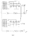
- FIG. 1 illustrates a prior art equipment configuration contained in a typical SCCS.
- eight different radios transmitting on eight different channels utilize a single antenna in a single sector.
- FIG. 1 depicts an equipment configuration in a typical SCCS for two sectors of a three-sector wireless communication system.
- the equipment configuration depicted on the top half of FIG. 1 is identical to that depicted on the bottom half of FIG. 1 .
- the equipment configuration for a third sector (not shown) is identical to the equipment configuration depicted for the other two sectors of FIG. 1 .
- FIG. 2 illustrates a typical three-sector wireless communications system.
- three different antennas In this three-sector system, three different antennas, one antenna per sector, transmit the signals produced by the radios depicted in FIG. 1 .
- a simple tower 240 acts as an installation point for three different antennas, Antenna A 220 , Antenna B 225 , and Antenna C 230 .
- these three antennas, 220 , 225 , and 230 may be attached to the top of a building or stadium.
- Sector A 205 occupies 120 degrees of transmit area.
- Antenna A 220 which is typically a unidirectional antenna, transmits in this 120 degrees of area.
- Antenna B 225 operates in Sector B 210 .
- Antenna B 225 transmits in the 120 degree area occupied by Sector B 210 .
- Antenna C 230 transmits in the 120 degree area occupied by Sector C 215 .
- the three antennas, 220 , 225 , and 230 are typically unidirectional antennas that transmit in their designated sectors.
- the equipment configuration depicted on the top half of FIG. 1 transmits in Sector A, while the equipment configuration depicted in the bottom half of FIG. 1 transmits on Sector B.
- a third equipment configuration identical to the two shown in FIG. 1 would be housed in an SCCS. This third equipment configuration (not shown) would transmit in Sector C.
- a maximum of eight radios can operate in a given sector of a three-sector communications system. While the typical radio configuration comprises seven radios, the illustration of FIG. 1 depicts eight radios per sector.
- Sector A 205 eight radios TRX1 102 , TRX2 104 , TRX3 106 , TRX4 108 , TRX5 110 , TRX6 112 , TRX7 114 , and TRX8 116 , are each connected to their respective Auto Tune Combiners.
- Auto Tune Combiners ATC1 118 , ATC2 120 , ATC3 122 , ATC4 124 , ATC5 126 , ATC6 128 , ATC7 130 , and ATC8 132 , are each connected to an Auto Tune Combiner Controller (ATCC) 134 .
- ATCC Auto Tune Combiner Controller
- the eight Auto Tune Combiners, 118 – 132 are sequentially connected to one another.
- the output of the eight Auto Tune Combiners, 118 – 132 is connected to a band pass filter TXBP 136 .
- Multi-coupler unit 138 serves to interconnect band pass filter 136 , radio frequency test loop device (RFTL) 140 , and Antenna A 220 .
- RFTL radio frequency test loop device
- multi-coupler unit (MCU) 138 serves to connect band pass filter 136 with RFTL 140 .
- RFTL 140 is connected to multi-coupler 142 .
- Multi-coupler 142 is then connected to TRX1 through TRX8, 102 – 116 .
- the first through the eighth radios, 102 – 116 are each housed in a cabinet at the SCCS site.
- Each of these eight radios is usually a 30 Watt radio.
- Each of the eight different radios, 102 – 116 produces a radio signal at a different frequency or on a different channel.
- the number of transmit radios is limited by the space available in the cabinet. In this case, as mentioned, the space constraints limit the transmit capability to eight radios per sector.
- the set of eight Auto Tune Combiners, 118 – 132 processes the output of the eight radios, 102 – 116 , to which they are connected.
- the Auto Tune Combiners operate to combine the radio signals generated by the first through eighth radios, 102 – 116 , to maximize power output to Antenna A 220 .
- These Auto Tune Combiners provide automatic combining of a set number of transmit channels. Further, these Auto Tune Combiners typically monitor the change in operating frequency and power of their corresponding transmitters or radios and automatically tune each channel to the correct operating frequency.
- the eight Auto Tune Combiners, 118 – 132 are sequentially connected so that a single output signal is generated from the eight different signals generated by the eight radios, 102 – 116 .
- the Auto Tune Combiners, 118 – 132 combine the eight different signals produced by the eight radios, 102 – 116 , into a single output signal for transmission on Antenna A 220 .
- Band pass filter 136 operates to filter the output of the Auto Tune Combiners, 118 – 132 .
- Band pass filter 136 ensures that the signal transmitted on Antenna A 220 falls within a specified frequency range.
- a wireless provider is allotted a specific bandwidth or spectrum on which to transmit.
- a wireless carrier may be allotted 5 MHz of bandwidth.
- the band pass filter 136 then operates to filter any signals that fall outside this allotted 5 MHz bandwidth.
- MCU 138 serves as a connection point for Antenna A 220 , band pass filter 136 , and RFTL 140 .
- MCU 138 typically has a single connection port for an antenna and multiple connection ports for one or more RFTL devices.
- MCU 138 may provide a test port for a forward signal and a reflected signal.
- RFTL 140 typically samples the forward signal and reflected signal from MCU 138 . RFTL 140 performs tests on the sampled signals in order to ascertain whether the first through the eighth radios, 102 – 116 , as well as Antenna A 220 , are operating properly. Typically, RFTL 140 performs a voltage standing wave ratio (VSWR) measurement to determine if Antenna A 220 is operating properly. In addition, RFTL 140 typically performs tests on the sampled forward and reflected signals to determine if the first through the eighth radios, 102 – 116 , are operating at a proper power level. RFTL 140 then produces a feedback signal, denoted by the dashed line, which controls the radios, 102 – 116 .
- VSWR voltage standing wave ratio
- Multi-coupler 142 simply serves as a connection between RFTL 140 and the first through the eighth radios, 102 – 116 .
- first through eighth radios of Sector B, 150 – 164 are interconnected to first through eighth Auto Tune Combiners of Sector B, 166 – 180 .
- These eight radios and eight Auto Tune Combiners operate in the same manner as those previously described with reference to Sector A 205 .
- the output of these eight Auto Tune Combiners, 166 – 180 is filtered by band pass filter 184 .
- the filtered signal is then transmitted on Antenna B 225 .
- RFTL 188 samples from multi-coupler unit 186 a forward and reflected signal.
- RFTL 188 after performing tests on the forward and reflected signals, sends a feedback signal to the eight radios, 150 – 164 . In this manner, the configuration of Sector B 225 operates in the same manner as that of Sector A 205 .
- the prior art SCCS limits the amount of transmission capability on a given sector in a multi-sector wireless communications system. Due to equipment and footprint limitations inherent in an SCCS, the standard configuration depicted in FIG. 1 is difficult to alter. As discussed, in order to provide more transmission capability in a given sector, it is often necessary to add a second SCCS and a second set of antennas.
- a stadium 235 may occupy a single sector, such as Sector B 225 .
- Sector B 225 a single sector
- the standard SCCS configuration such as that of the Ericsson RBS884 system, does not allow for the configuration of radios to increase the transmission capability in a given sector.
- Embodiments of the present invention are directed at overcoming one or more of the above issues.
- a method for transmitting signals in a multi-sector wireless communications system includes generating a first signal from a first signal source associated with a first sector, processing the first signal, generating a second signal from a second signal source associated with a second sector, processing the second signal, combining the processed first signal with the processed second signal, and transmitting the combined processed first and second signals in the second sector.
- a method for transmitting signals in a multi-sector wireless communications system includes generating a first signal from a first signal source associated with a first sector, processing the first signal, transmitting the processed first signal on a first antenna associated with a first sector, generating a second signal from a second signal source associated with the first sector, processing the second signal, generating a third signal from a third signal source associated with a second sector, processing the third signal, combining the processed second and third signals, and transmitting the combined processed second and third signals on a second antenna associated with the second sector.
- a system for transmitting signals in a multi-sector wireless communications system includes a first signal source associated with a first sector for generating a first signal, a first Auto Tune Combiner for processing the first signal, a second signal source associated with a second sector for generating a second signal, a second Auto Tune Combiner for processing the second signal and for combining the processed first signal with the processed second signal, and an antenna associated with the second sector for transmitting the combined processed first and second signals wherein the first Auto Tune Combiner is connected to the second Auto Tune Combiner with an extension cable.
- a system for transmitting signals in a multi-sector wireless communications system includes a first signal source associated with a first sector for generating a first signal, a first Auto Tune Combiner for processing the first signal, a first antenna associated with the first sector for transmitting the processed first signal, a second signal source associated with the first sector for generating a second signal, a second Auto Tune Combiner for processing the second signal, a third signal source associated with a second sector for generating a third signal, a third Auto Tune Combiner for processing the third signal and for combining the processed second and third signals, and a second antenna associated with the second sector for transmitting the combined processed second and third signals wherein the second Auto Tune Combiner is connected to the third Auto Tune Combiner with an extension cable.
- a method for increasing the number of transmitting devices in a sector of a multi-sector wireless communications system includes connecting a first number of radio sources to an equal first number of Auto Tune Combiners associated with a first sector, connecting a second number of radio sources to an equal second number of Auto Tune Combiners associated with a second sector, and connecting the first number of Auto Tune Combiners in the first sector to the second number of Auto Tune Combiners in the second sector so that the first number of radio sources associated with the first sector and the second number of radio sources associated with the second sector transmit in the second sector.
- a method for increasing the number of transmitting devices in a sector of a multi-sector wireless communications system includes connecting a first number of radio sources to an equal first number of Auto Tune Combiners associated with a first sector, connecting a second number of radio sources to an equal second number of Auto Tune Combiners associated with the first sector, connecting a third number of radio sources to an equal third number of Auto Tune Combiners associated with a second sector, and connecting the second number of Auto Tune Combiners in the first sector to the third number of Auto Tune Combiners in the second sector so that the second number of radio sources associated with the first sector and the third number of radio sources associated with the second sector transmit in the second sector.
- FIG. 1 is a block diagram of a typical self-contained cell site configuration of the prior art.
- FIG. 2 is a diagram of a three-sector wireless communications system.
- FIG. 3 is a block diagram of a wireless communications system consistent with the principles of the present invention.
- FIG. 4 is a wiring diagram of a wireless communications system consistent with the principles of the present invention.
- FIG. 5 is a flow chart of the operation of a wireless communications system consistent with the principles of the present invention.
- FIG. 6 is a flow chart depicting the assembly of a wireless communications system consistent with the principles of the present invention.
- a system for increasing the transmit capability of a single sector in a multi-sector communications system may include a first set of radios associated with a first sector, a second set of radios associated with the first sector, a first set of Auto Tune Combiners associated with the first sector, a second set of Auto Tune Combiners associated with the first sector, a first band pass filter associated with the first sector, a first multi-coupler unit associated with the first sector, an antenna associated with the first sector, a radio frequency test loop device associated with the first sector, a multi-coupler associated with the first sector, a third set of radios associated with a second sector, a third set of Auto Tune Combiners associated with the second sector, a band pass filter associated with the second sector, a multi-coupler unit associated with the second sector, an antenna associated with the second sector, a radio frequency test loop device associated with the second sector, and a multi-coupler associated with the second sector.
- an exemplary embodiment of a system for increasing the transmit capability of a single sector in a multi-sector communications system includes: a first radio (TRX1) 302 , a second radio (TRX2) 304 , a third radio (TRX3) 306 , a fourth radio (TRX4) 308 , a fifth radio (TRX5) 310 , a sixth radio (TRX6) 312 , a seventh radio (TRX7) 314 , an eighth radio (TRX8) 316 , a first power splitter device (PSP1) 344 , a first Auto Tune Combiner (ATC1) 318 , a second Auto Tune Combiner (ATC2) 320 , a third Auto Tune Combiner (ATC3) 322 , a fourth Auto Tune Combiner (ATC4) 324 , a fifth Auto Tune Combiner (ATC5) 326 , a sixth Auto Tune Combiner (ATC6) 328 , a seventh Auto Tun
- TRX1 302 is connected to ATC1 318
- TRX2 304 is connected to ATC2 320
- TRX3 306 is connected to ATC3 322
- TRX4 308 is connected ATC4 324
- TRX5 310 is connected to ATC5 326
- TRX6 312 is connected to ATC6 328
- TRX7 314 is connected to ATC7 330
- TRX8 316 is connected to ATC8 332 .
- PSP1 344 is connected to each of the first eight radios, 302 – 316 .
- ATCC1 334 is connected to and controls each of the first eight Auto Tune Combiners, 318 – 332 .
- ATC1 318 , ATC2 320 , ATC3 322 , and ATC4 324 are all sequentially connected.
- ATC5 326 , ATC6 328 , ATC7 330 , and ATC8 332 are also sequentially connected.
- the first four Auto Tune Combiners, ATC1 318 , ATC2 320 , ATC3 322 , and ATC4 324 are not connected to the second set of four Auto Tune Combiners, ATC5 326 , ATC6 328 , ATC7 330 , and ATC8 332 .
- the output of the first set of Auto Tune Combiners, ATC1 318 , ATC2 320 , ATC3 322 , and ATC4 324 are connected to the first band pass filter 336 .
- the first band pass filter 336 is connected to MCU1 338 .
- MCU1 338 serves to interconnect first band pass filter 336 , Antenna A 220 , and RFTL1 340 .
- RFTL1 340 is connected to MCU1 and first multi-coupler 342 .
- First multi-coupler 342 is connected to the first through the fourth radios, 302 – 308 .
- TRX9 350 is connected to ATC9 366
- TRX10 352 is connected to ATC10 368
- TRX11 354 is connected to ATC11 370
- TRX12 356 is connected to ATC12 372
- TRX13 358 is connected to ATC13 374
- TRX14 360 is connected to ATC14 376
- TRX14 362 is connected to ATC15 378
- TRX16 364 is connected to ATC16 380 .
- This second set of eight ATC's, 366 – 380 are all sequentially connected.
- ATC9 366 , ATC10 368 , ATC11 370 , ATC12 372 , ATC13 374 , ATC14 376 , ATC15 378 , and ATC16 380 are all sequentially connected.
- ATCC2 382 is connected to each of these eight Auto Tune Combiners, 366 – 380 .
- the output of these sequentially connected Auto Tune Combiners, 366 – 380 is connected to second band pass filter 384 .
- Second band pass filter 384 is connected to MCU2 386 .
- MCU2 386 serves to interconnect second band pass filter 384 , Antenna B 225 , and RFTL2 388 .
- RFTL2 388 is connected to MCU2 386 and second multi-coupler 390 .
- Second multi-coupler 390 is then connected to the fifth through eighth radios, 310 – 316 , and ninth through sixteenth radios, 350 – 364 .
- First multi-coupler 342 interconnects RFTL1 340 to first through fourth radios, 302 – 308 .
- second multi-coupler 390 interconnects RFTL2 388 with the fifth through eighth radios, 310 – 316 , as well as the ninth through sixteenth radios, 350 – 364 .
- the exemplary embodiment of FIG. 3 contains connections between the components associated with Sector A 205 and the components associated with Sector B 210 .
- the prior art configuration of an SCCS comprises eight radios or transmitters per sector. In the exemplary embodiment of FIG. 3 , however, four of the radios, 310 – 316 , and four of the Auto Tune Combiners, 326 – 332 , are connected to the devices associated with Sector B 210 .
- ATC8 332 is connected to ATC9 366 .
- ATC5 326 , ATC6 328 , ATC7 330 , and ATC8 332 which are all sequentially connected, are then connected to ATC9 366 through ATC16 380 . Therefore, ATC5 326 through ATC16 380 are all sequentially connected.
- a transmit path for transmission on Antenna B 225 is formed by the interconnection of the Auto Tune Combiners, ATC5 326 through ATC8 332 and ATC9 366 through ATC16 380 .
- the receive path or reflected path from Antenna B 225 is implemented in this configuration with the connection between PSP1 344 and PSP2 392 .
- connections between the components depicted in FIG. 3 are typically implemented with cables, such as coaxial cables.
- the interconnection between these devices may be achieved in any convenient manner.
- the interconnection between these devices can be implemented with cables or by wireless means.
- FIG. 2 an example of an antenna configuration associated with a multi-sector wireless communications system is depicted. As previously described, this wireless communications system is divided into three different sectors, Sector A 205 , Sector B 210 , and Sector C 215 . Each of these three sectors divides the total transmit area into sectors of 120 degrees each. In this typical configuration, each sector has associated with it a single antenna. Antenna A 220 transmits in the 120 degree area occupied by Sector A 205 . Likewise, Antenna B 225 transmits in the 120 degree area associated with Sector B 210 . Antenna C 230 transmits in the 120degree area associated with Sector C 215 .
- a tower 240 may be associated with the multi-sector wireless communications system. This tower 240 may serve as a mounting point for the three antennas, 220 , 225 , and 230 . Alternatively, the three antennas may be mounted on the top of a building or stadium.
- Antenna A 220 and Antenna B 225 are associated with Sector A 205 and Sector B 210 , respectively.
- the principles of the present invention may be extended to a third sector, such as Sector C 215 .
- a third sector such as Sector C 215 .
- any number of radios or transmit devices associated with a first sector may be coupled to transmit with the radios associated with a second sector.
- a third set of eight radios and eight Auto Tune Combiners may occupy an SCCS associated with Sector C 216 .
- any number of the eight radios and eight Auto Tune Combiners associated with Sector C may be cabled together with the radios and Auto Tune Combiners associated with Sector B. Therefore, Sector B, in addition to gaining the transmit capabilities of the fifth through eighth radios of Sector A may gain additional transmit capabilities associated with Sector C.
- the 24 total radios that may be-housed in a single SCCS can be split in any way among three different sectors.
- the 24 Auto Tune Combiners which are associated with the 24 radios may also be split in any manner among the three different sectors. For example, two radios could transmit on Sector A, two radios could transmit on Sector C, and 20 radios could transmit on Sector B. Alternatively, all the radios could transmit on Sector B.
- the sixteen radios, TRX1 302 through TRX8 316 and TRX9 350 through TRX16 364 are generally any type of signal source.
- these sixteen radios are 30 Watt radios that each produce a signal on a different frequency or on a different channel.
- TRX1 302 produces a first signal on a first channel or frequency
- TRX2 304 produces a second signal on a second channel or frequency.
- the remaining radios, 306 – 316 and 350 – 364 each produce signals on different frequencies or on different channels.
- these radios can be of any wattage and generate signals of any frequency.
- these radios can be any type of radio frequency or signal source.
- these sixteen radios are 30 Watt radios.
- these radios depending on the wireless communications system, may transmit in any band, e.g., 850 MHz, 900 MHz, 1800 MHz, or 1900 MHz.
- the sixteen Auto Tune Combiners, ATC1 318 –ATC8 332 , and ATC9 366 –ATC16 380 serve to process the output of the sixteen different radios.
- an Auto Tune Combiner such as ATC1 318 , combines all of the frequencies from the various radio frequency sources to get maximum power output to the antenna.
- These Auto Tune Combiners provide automatic combining of a set number of transmit channels. Further, these Auto Tune Combiners typically monitor the change in operating frequency and power of their corresponding transmitters and automatically tune each channel to the correct operating frequency.
- ATC1 through ATC8, 318 – 332 are controlled by ATCC1 334 .
- ATC9 through ATC16, 366 – 380 are controlled by ATCC2 382 .
- ATCC1 334 and ATCC2 382 serve to control the function of the Auto Tune Combiners to which they are connected.
- the band pass filters, 336 and 384 filter the output of the Auto Tune Combiners so that the signal transmitted on the antennas, 220 and 225 , are within a designated bandwidth. Since a particular wireless communications system is allotted a particular spectrum on which to transmit, the band pass filters, 336 and 384 , ensure that transmissions on the antennas, 220 and 225 , occur within the allotted spectrum. In this manner, the band pass filters, as is known in the art, filter the output of the Auto Tune Combiners to which they are connected so that the signal transmitted on the antennas does not fall outside the bandwidth allocated to the wireless provider. For example, a wireless provider, in an e-band system, may be provided 5 MHz of bandwidth in which to transmit.
- band pass filters in this example, would then filter the output of their respective Auto Tune Combiners so as to ensure that the transmitted signal falls within the allocated 5 MHz bandwidth.
- the two band pass filters each function to filter out any signals that fall outside of the specified 5 MHz bandwidth.
- the operation of band pass filters is known to those skilled in the art, and band pass filters are easily obtainable from any number of manufacturers.
- MCU1 338 and MCU2 386 each have a connection port for their respective antennas, Antenna A 220 and Antenna B 225 .
- MCU1 338 and MCU2 386 have test ports by which RFTL1 340 and RFTL2 388 sample a forward signal and a reflected signal.
- MCU1 338 and MCU2 386 each have two forward signal test ports and two reflected signal test ports. In this manner, two different radio frequency test loop devices may be connected to a single multi-coupler unit, such as MCU1 338 or MCU2 386 .
- the antennas of the embodiment of FIG. 3 , Antenna A 220 and Antenna B 225 are typically unidirectional antennas, but may be antennas of any type.
- the three antennas depicted are directional antennas which each transmit in their respective sectors.
- Antenna A 220 transmits in Sector A 205 .
- Antenna A 220 is a unidirectional antenna that transmits in the 120 degree area comprising Sector A 205 .
- Antenna B 225 and Antenna C 230 are also unidirectional antennas that transmit in the 120 degree areas occupying Sector B 210 and Sector C 215 , respectively.
- a wireless communications system may be divided into any number of sectors, each with associated antennas.
- the antennas in a particular sector are typically configured to transmit only in that sector.
- an omni-directional antenna may be used which transmits over the entire 360 degree area. The operation of these antennas is commonly known, and these antennas can be obtained from any number of wireless equipment providers, such as Ericsson.
- RFTL1 340 and RFTL2 388 sample both the forward and reflected signals from MCU1 338 and MCU2 386 , respectively.
- RFTL1 340 samples the forward path for the signal that is actually transmitted on Antenna A 220 through the forward port of MCU1 338 (not shown).
- RFTL1 340 samples the reflected path from the reflected port of MCU1 338 (not shown).
- RFTL1 340 and RFTL2 388 each serve to verify that the radios to which they are connected are operating at the proper power.
- RFTL1 340 and RFTL2 388 also verify that Antenna A 220 and Antenna B 225 are operating properly.
- RFTL1 340 and RFTL2 388 each send feedback signals through first multi-coupler 342 and second multi-coupler 390 to their respective radios.
- the feedback signal generated by RFTL1 340 and RFTL2 388 is indicated by the dashed lines.
- RFTL1 340 operates to control first through fourth radios, 302 – 308 .
- RFTL2 388 serves to control the fifth through the eighth radios, 310 – 316 , as well as the ninth through the sixteenth radios, 305 – 316 .
- RFTL1 340 and RFTL2 388 perform voltage standing wave ratio (VSWR) measurements to ensure that the wireless communications system is operating properly.
- VSWR voltage standing wave ratio
- the sixteen radios, 302 – 316 and 350 – 364 each generate a radio signal on different frequencies or on different channels.
- TRX1 302 generates a first signal at a first frequency or on a first channel
- TRX2 304 generates a signal that is carried-on a second frequency or on a second channel.
- the remaining radios each generate signals at specific frequencies or on specific channels.
- the sixteen radios depicted in FIG. 3 each generate a signal at a different frequency or on a different channel.
- the first through fourth radios may generate signals at four different frequencies for transmission in Sector A 205 .
- the fifth through eighth radios, 310 – 316 , as well as the ninth through sixteenth radios, 350 – 364 , may each generate signals at different frequencies or on different channels for transmission is Sector B 210 . While the radios that transmit on a particular sector do not generate signals at the same frequency or on the same channel, the radios that transmit on different sectors may generate signals that are on the same frequency or channel. For example, TRX4 308 may generate a radio signal at a specific frequency or on a specific channel, while TRX15 362 generates a signal that is at the same frequency or on the same channel. This is permissible because TRX4 308 eventually transmits on Antenna A 220 associated with Sector A 205 while TRX5 310 eventually transmits on Antenna B 225 associated with Sector B 210 .
- the signals generated by each of the sixteen radios are then fed into their respective Auto Tune Combiners.
- the signal generated by TRX6 312 is processed by ATC6 328 .
- the first four Auto Tune Combiners, ATC1 318 , ATC2 320 , ATC3 322 , and ATC4 324 are all sequentially connected.
- the four signals generated by the first four radios, 302 – 308 while processed by their connected Auto Tune Combiners, 318 – 324 , are all combined into a single output that is filtered by first band pass filter 336 .
- the first four Auto Tune Combiners, 318 – 324 combine the four different signals generated by the first four radios, 302 – 308 , into a single output signal.
- the fifth through the eighth radios, 310 – 316 , as well as the ninth through the sixteenth radios, 350 – 364 each have their signals processed by the Auto Tune Combiners to which they are connected.
- the signal generated by TRX7 314 is processed by ATC7 330 .
- the output of the first four Auto Tune Combiners, 318 – 324 is then filtered by first band pass filter 336 .
- First band pass filter 336 ensures that the signal eventually transmitted on Antenna A 220 in Sector A 205 is within the allotted spectrum or bandwidth assigned to a particular wireless provider.
- the filtered signal is then transmitted on Antenna A 220 in Sector A 205 .
- the second band pass filter 384 filters the output of the second set of Auto Tune Combiners, ATC5 through ATC8, 336 – 332 , and ATC9 through-ATC16, 366 – 380 .
- the second band pass filter ensures that the output signal of the second set of Auto Tune Combiners falls within a pre-specified bandwidth or spectrum.
- Second band pass filter 384 like first band pass filter 336 , filters any signals that fall outside the spectrum or bandwidth allotted to a particular wireless provider. The filtered signal is then transmitted on Antenna B 225 in Sector B 210 .
- RFTL1 340 samples the signal that is transmitted on Antenna A (the forward path), as well as the reflected path signal. RFTL1 340 performs various tests on the forward path signal and the reflected path signal to determine if the first through fourth radios, 302 – 308 , are operating at a proper power. In addition, RFTL1 340 may perform other measurements, such as measurements to ascertain whether Antenna A 220 is operating properly. RFTL1 340 , after performing these measurements and tests, generates a feedback signal that is returned to the first through fourth radios, 302 – 308 .
- RFTL1 340 may perform tests on the forward and reflected path signals to ascertain that one of the first four radios, 302 – 308 , is operating at an improper power level. In such a case, RFTL1 340 sends a feedback signal via first multi-coupler 340 to the radio that is operating at an improper power level.
- RFTL2 388 samples a forward path signal and a reflected path signal from Antenna B 225 .
- RFTL2 388 essentially monitors the signals that are generated by the fifth through eighth radios, 310 – 316 , as well as the ninth through sixteenth radios, 350 – 364 .
- RFTL2 388 samples the forward and reflected signals that are associated with Antenna B 225 .
- RFTL2 388 like RFTL1 340 , performs various tests on the sampled signals. As noted, one such test may be to verify that Antenna B 225 is operating properly.
- RFTL2 388 sends a feedback signal via second multi-coupler 390 to the improperly operating radio.
- TRX10 352 may be operating at a low power level.
- RFTL2 388 after sampling the forward and reflected signals associated with Antenna B 225 and performing tests on those signals, sends a feedback signal (depicted by the dashed line) to TRX10 352 .
- This feedback signal may initiate an increase in the power level at which TRX10 352 operates.
- the configuration depicted in FIG. 3 allows greater transmit capacity on a given sector.
- the radios from a first sector may be utilized to transmit on a second sector.
- the fifth through the eighth radios, 310 – 316 which are associated with Sector A, are interconnected via their Auto Tune Combiners, 336 – 332 , so that the fifth through eighth radios, 310 – 316 , transmit on Antenna B 225 associated with Sector B 210 .
- interconnecting the Auto Tune Combiners and the Auto Tune Combiner Controllers allows radios from one sector to transmit on an antenna associated with a second different sector.
- connection between PSP1 344 and PSP2 392 allows the receive paths of fifth through eighth radios, 310 – 316 , as well as ninth through sixteenth radios, 350 – 364 , to be associated with Antenna B 225 . Therefore, by connecting the Auto Tune Combiners, Auto Tune Combiner Controllers, and PSP cards, as depicted in FIG. 3 , an SCCS can be configured so that the radios associated with one sector can be utilized on a second sector.
- the configuration of FIG. 3 may be utilized in cases in which a given sector has a much higher demand than the remaining two sectors.
- the three antennas depicted in FIG. 2 may be mounted such that Antenna B 225 serves the football stadium 235 .
- the demand in the stadium 235 may significantly outweigh the demand seen in the other two sectors, Sector A 205 and Sector C 215 .
- each of the three sectors depicted in FIG. 2 may contain two antennas.
- each antenna typically has associated with it eight different radios. Therefore, two SCCS's may be necessary for a three-sector communications system with two antennas per sector.
- the radios associated with a first sector may be used to increase the transmit capabilities on a second sector.
- the transmit capability of a given sector in a multi-sector communications system with multiple antennas per sector can be configured so that the transmit capability of a single sector is increased while decreasing the transmit capabilities of a second sector.
- the transmit capabilities of a single antenna may be increased while decreasing the transmit capabilities of a second different antenna. While the embodiment of FIG. 3 depicts eight radios per antenna, any number of radios and Auto Tune Combiners per antenna may be implemented using the principles of the present invention.
- FIGS. 4A and 4B depict a wiring diagram for some of the components of the exemplary embodiment of FIG. 3 .
- Some of the components of FIG. 3 are depicted in FIG. 4 much as they would appear contained in a cabinet contained in an SCCS.
- the first through eighth radios, 302 – 316 , as well as PSP1 344 are each contained within a cabinet 422 .
- the ninth through sixteenth radios, 350 – 364 , as well as PSP2 392 are contained in cabinet 420 . While other configurations of components and cabinets is well within the scope of the present invention, the exemplary embodiment of FIG. 4 depicts a typical configuration consistent with the Ericsson RBS884 system.
- Multi-coupler 342 is interconnected to PSP2 392 and PSP1 344 .
- Multi-coupler 390 is interconnected to PSP1 344 .
- ATCC1 334 and ATCC2 382 are interconnected.
- the different sets of Auto Tune Combiners associated with two different sectors are connected with cable 408 .
- cabinet 420 contains the ninth through sixteenth radios, 350 – 364 , as well as PSP2 392 .
- Cabinet 422 contains the first through the eighth radios, 302 – 316 , as well as PSP1 344 .
- cabinet 422 is associated with Sector A 205
- cabinet 420 is associated with Sector B 210 .
- four of the eight radios contained in cabinet 422 transmit on Sector B, while the remaining four radios transmit on Sector A 205 .
- cabinet 424 contains eight Auto Tune Combiners. These Auto Tune Combiners are all sequentially connected with U-Links, 402 , 404 , and 406 .
- cabinet 426 contains a second set of Auto Tune Combiners. The first through fourth Auto Tune Combiners, 318 , 320 , 322 , 324 , are interconnected with U-Link 416 , while the fifth through eighth Auto Tune Combiners, 326 , 328 , 330 , 332 , are connected with U-Link 410 .
- cabinet 424 is associated with Sector B and cabinet 426 is associated with Sector A. In this case, however, the Auto Tune Combiners contained in cabinet 424 are interconnected with four of the Auto Tune Combiners contained in cabinet 426 .
- ATCC1 334 and ATCC2 382 are also interconnected.
- Cabinet 428 contains multi-coupler 342
- cabinet 430 contains multi-coupler 390
- cabinet 430 is associated with Sector B
- cabinet 428 is associated with Sector A.
- the multi-coupler associated with Sector B is connected to PSP2 392 , as well as PSP1 344 .
- the ninth through the sixteenth radios, 350 – 364 as well as TRX2 304 , TRX4 308 , TRX6 312 , and TRX8 316 , are connected such that they transmit on Sector B.
- Multi-coupler 342 which is associated with Sector A, is connected to PSP1 344 . In this manner, TRX1 302 , TRX3 306 , TRX5 310 , and TRX7 314 transmit on Sector A.
- FIG. 5 is flow chart depicting the operation of the exemplary embodiment depicted in FIG. 3 .
- the two different flow charts comprising FIG. 5 may operate in parallel.
- a first set of radios associated with a first sector generates a first set of signals.
- the combined first set of signals is filtered by a band pass filter.
- the combined first set of signals is sent to a multi-coupler unit for transmission on an antenna in a first sector.
- First RFTL card samples the combined first set of signals. As previously described, the first RFTL card, after sampling the signals, performs various tests on the signals. One such test may be to determine whether one of the first set of radios is operating at an improper power level.
- step 555 the RFTL card determines if the power of one of the radios needs adjusting. If the power does not need adjusting, then flow proceeds to step 545 in which the first RFTL card continues to sample the combined first set of signals. If the power does need adjusting, then flow proceeds to step 565 , in which a feedback signal is sent to one of the first set of radios, thereby adjusting its power.
- a second set of radios associated with the first sector generates a second set of signals.
- a third set of radios associated with a second sector generates a third set of signals.
- a second set of Auto Tune Combiners combines the second and third sets of signals.
- the combined second and third sets of signals is filtered by a band pass filter. Flow then proceeds to step 550 , in which the combined second and third sets of signals are sent to a multi-coupler unit for transmission on an antenna in a second sector.
- a second RFTL card samples the combined second and third sets of signals.
- an RFTL card may perform any number of different tests on the sampled signals.
- One such test is to ascertain whether one of the second or third sets of radios is operating at an improper power level.
- This test is depicted in step 570 , in which the RFTL card determines whether one of the radios in the second or third set of radios needs its power adjusted. If the power of the radios does not need adjusting, then flow proceeds to step 560 , in which the second RFTL card continues to sample the combined second and third sets of signals. If the power of one of the second or third sets of radios needs adjusting, then flow proceeds to step 580 , in which the RFTL card sends a feedback signal to the improperly operating radio so that its power can be adjusted.
- FIG. 6 is a flow chart depicting the connection of the components depicted in FIGS. 3 and 4 .
- a first number of radios is connected to an equal first number of Auto Tune Combiners associated with a first sector.
- a second number of radios is connected to an equal second number of Auto Tune Combiners associated with the first sector.
- a third number of radios is connected to an equal third number of Auto Tune Combiners associated with a second sector.
- the second number of Auto Tune Combiners in the first sector is connected to the third number of Auto Tune Combiners in the second sector.
- signals from the second number of radio sources associated with the first sector and the third number of radio sources associated with the second sector are transmitted in the second sector.
Abstract
Description
Claims (17)
Priority Applications (1)
| Application Number | Priority Date | Filing Date | Title |
|---|---|---|---|
| US10/244,165 US7242930B2 (en) | 2002-09-13 | 2002-09-13 | System and method for increasing transmission capability |
Applications Claiming Priority (1)
| Application Number | Priority Date | Filing Date | Title |
|---|---|---|---|
| US10/244,165 US7242930B2 (en) | 2002-09-13 | 2002-09-13 | System and method for increasing transmission capability |
Publications (2)
| Publication Number | Publication Date |
|---|---|
| US20040053608A1 US20040053608A1 (en) | 2004-03-18 |
| US7242930B2 true US7242930B2 (en) | 2007-07-10 |
Family
ID=31991844
Family Applications (1)
| Application Number | Title | Priority Date | Filing Date |
|---|---|---|---|
| US10/244,165 Expired - Fee Related US7242930B2 (en) | 2002-09-13 | 2002-09-13 | System and method for increasing transmission capability |
Country Status (1)
| Country | Link |
|---|---|
| US (1) | US7242930B2 (en) |
Cited By (1)
| Publication number | Priority date | Publication date | Assignee | Title |
|---|---|---|---|---|
| US7551923B1 (en) * | 2002-09-13 | 2009-06-23 | At&T Mobility Ii Llc | System and method for improved spectrum use |
Families Citing this family (1)
| Publication number | Priority date | Publication date | Assignee | Title |
|---|---|---|---|---|
| US7200393B2 (en) * | 2002-09-13 | 2007-04-03 | Cingular Wireless Ii, Llc | System for split transmission for enhanced spectrum utilization |
Citations (19)
| Publication number | Priority date | Publication date | Assignee | Title |
|---|---|---|---|---|
| US5521904A (en) * | 1993-12-07 | 1996-05-28 | Telefonaktiebolaget Lm Ericsson | Method and apparatus for testing a base station in a time division multiple access radio communications system |
| US5574981A (en) | 1992-12-30 | 1996-11-12 | Nokia Telecommunications Oy | Method and arrangement for measuring the condition of a receiver antenna |
| US5854986A (en) * | 1995-05-19 | 1998-12-29 | Northern Telecom Limited | Cellular communication system having device coupling distribution of antennas to plurality of transceivers |
| US6167286A (en) | 1997-06-05 | 2000-12-26 | Nortel Networks Corporation | Multi-beam antenna system for cellular radio base stations |
| US6246674B1 (en) * | 1997-01-27 | 2001-06-12 | Metawave Communications Corporation | Antenna deployment sector cell shaping system and method |
| US20020077154A1 (en) * | 2000-12-19 | 2002-06-20 | Judson Bruce A. | Base station antenna sharing |
| US20020103001A1 (en) | 2001-02-01 | 2002-08-01 | Haim Weissman | Dynamic capacity allocation of in-building system |
| US20020119772A1 (en) * | 2001-02-26 | 2002-08-29 | Nec Corporation | Base station testing apparatus and method for testing a base station in a CDMA communication system |
| US20020137547A1 (en) * | 2001-02-07 | 2002-09-26 | Judson Bruce A. | Antenna array and method therefor |
| US6470193B1 (en) * | 1997-04-11 | 2002-10-22 | Telefonaktiebolaget L M Ericsson (Publ) | Power efficient indoor radio base station |
| US6516206B2 (en) | 1999-09-30 | 2003-02-04 | Nokia Networks Oy | Transceiver operation in radio system |
| US20030073463A1 (en) | 1997-03-03 | 2003-04-17 | Joseph Shapira | Active antenna array configuration and control for cellular communication systems |
| US20030139140A1 (en) | 2002-01-23 | 2003-07-24 | Tao Chen | Selective combining of multiple non-synchronous transmissions in a wireless communication system |
| US6640111B1 (en) | 1997-03-03 | 2003-10-28 | Celletra Ltd. | Cellular communications systems |
| US20030236089A1 (en) | 2002-02-15 | 2003-12-25 | Steffen Beyme | Wireless simulator |
| US20040053583A1 (en) * | 2002-09-13 | 2004-03-18 | David Bogart | System and method for improved spectrum use |
| US6711388B1 (en) | 2000-03-30 | 2004-03-23 | Nokia Corporation | Distributed power level control system of transmitter for cellular communication |
| US6804540B1 (en) * | 2000-08-02 | 2004-10-12 | Ericsson Inc. | Remote band-pass filter in a distributed antenna system |
| US20040204107A1 (en) * | 2002-09-13 | 2004-10-14 | David Bogart | System for split transmission for enhanced spectrum utilization |
-
2002
- 2002-09-13 US US10/244,165 patent/US7242930B2/en not_active Expired - Fee Related
Patent Citations (19)
| Publication number | Priority date | Publication date | Assignee | Title |
|---|---|---|---|---|
| US5574981A (en) | 1992-12-30 | 1996-11-12 | Nokia Telecommunications Oy | Method and arrangement for measuring the condition of a receiver antenna |
| US5521904A (en) * | 1993-12-07 | 1996-05-28 | Telefonaktiebolaget Lm Ericsson | Method and apparatus for testing a base station in a time division multiple access radio communications system |
| US5854986A (en) * | 1995-05-19 | 1998-12-29 | Northern Telecom Limited | Cellular communication system having device coupling distribution of antennas to plurality of transceivers |
| US6246674B1 (en) * | 1997-01-27 | 2001-06-12 | Metawave Communications Corporation | Antenna deployment sector cell shaping system and method |
| US6640111B1 (en) | 1997-03-03 | 2003-10-28 | Celletra Ltd. | Cellular communications systems |
| US20030073463A1 (en) | 1997-03-03 | 2003-04-17 | Joseph Shapira | Active antenna array configuration and control for cellular communication systems |
| US6470193B1 (en) * | 1997-04-11 | 2002-10-22 | Telefonaktiebolaget L M Ericsson (Publ) | Power efficient indoor radio base station |
| US6167286A (en) | 1997-06-05 | 2000-12-26 | Nortel Networks Corporation | Multi-beam antenna system for cellular radio base stations |
| US6516206B2 (en) | 1999-09-30 | 2003-02-04 | Nokia Networks Oy | Transceiver operation in radio system |
| US6711388B1 (en) | 2000-03-30 | 2004-03-23 | Nokia Corporation | Distributed power level control system of transmitter for cellular communication |
| US6804540B1 (en) * | 2000-08-02 | 2004-10-12 | Ericsson Inc. | Remote band-pass filter in a distributed antenna system |
| US20020077154A1 (en) * | 2000-12-19 | 2002-06-20 | Judson Bruce A. | Base station antenna sharing |
| US20020103001A1 (en) | 2001-02-01 | 2002-08-01 | Haim Weissman | Dynamic capacity allocation of in-building system |
| US20020137547A1 (en) * | 2001-02-07 | 2002-09-26 | Judson Bruce A. | Antenna array and method therefor |
| US20020119772A1 (en) * | 2001-02-26 | 2002-08-29 | Nec Corporation | Base station testing apparatus and method for testing a base station in a CDMA communication system |
| US20030139140A1 (en) | 2002-01-23 | 2003-07-24 | Tao Chen | Selective combining of multiple non-synchronous transmissions in a wireless communication system |
| US20030236089A1 (en) | 2002-02-15 | 2003-12-25 | Steffen Beyme | Wireless simulator |
| US20040053583A1 (en) * | 2002-09-13 | 2004-03-18 | David Bogart | System and method for improved spectrum use |
| US20040204107A1 (en) * | 2002-09-13 | 2004-10-14 | David Bogart | System for split transmission for enhanced spectrum utilization |
Cited By (1)
| Publication number | Priority date | Publication date | Assignee | Title |
|---|---|---|---|---|
| US7551923B1 (en) * | 2002-09-13 | 2009-06-23 | At&T Mobility Ii Llc | System and method for improved spectrum use |
Also Published As
| Publication number | Publication date |
|---|---|
| US20040053608A1 (en) | 2004-03-18 |
Similar Documents
| Publication | Publication Date | Title |
|---|---|---|
| US10938450B2 (en) | Base station router for distributed antenna systems | |
| US6006113A (en) | Radio signal scanning and targeting system for use in land mobile radio base sites | |
| US10594043B2 (en) | Antenna device and system having active modules | |
| US7328033B2 (en) | Wireless network system and method | |
| CN101911520B (en) | Apparatus and method for switching from reception to transmission | |
| US8185162B2 (en) | Electrically tilted antenna system with polarisation diversity | |
| JP2010506465A (en) | Centralized wireless communication system | |
| MXPA05010469A (en) | Phased array antenna system with variable electrical tilt. | |
| KR20050083785A (en) | Mobile radio base station | |
| US9270321B2 (en) | Flexible unified architecture for point-to-point digital microwave radios | |
| EP0725498B1 (en) | Radio signal scanning and targeting system for use in land mobile radio base sites | |
| JP2000252735A (en) | Tilt-adjustable antenna | |
| CN105453339A (en) | Methods and apparatus for antenna tuning | |
| Li et al. | Design and implementation of an active array antenna with remote controllable radiation patterns for mobile communications | |
| KR102608765B1 (en) | Distributed antenna system and operating method thereof | |
| US7551923B1 (en) | System and method for improved spectrum use | |
| US20210218152A1 (en) | Antenna apparatus | |
| US7242930B2 (en) | System and method for increasing transmission capability | |
| US20230275623A1 (en) | Radio transmission or reception apparatus and beam forming method thereof | |
| KR20100037666A (en) | Multi standby portable terminal | |
| CN115764261A (en) | Element feeding device, communication antenna and base station antenna | |
| US7200393B2 (en) | System for split transmission for enhanced spectrum utilization | |
| US20230387958A1 (en) | Multi-antenna transceiver system for multi-band operation | |
| CN111509405B (en) | Antenna module and electronic equipment | |
| KR20170117303A (en) | Distributed antenna system and signal processing method thereof |
Legal Events
| Date | Code | Title | Description |
|---|---|---|---|
| AS | Assignment |
Owner name: CINGULAR WIRELESS, LLC, GEORGIA Free format text: ASSIGNMENT OF ASSIGNORS INTEREST;ASSIGNORS:BOGART, DAVID;ERWIN, CHRIS;REEL/FRAME:013297/0632 Effective date: 20020903 |
|
| AS | Assignment |
Owner name: CINGULAR WIRELESS II, INC.,GEORGIA Free format text: ASSIGNMENT OF ASSIGNORS INTEREST;ASSIGNOR:CINGULAR WIRELESS, LLC;REEL/FRAME:016480/0826 Effective date: 20041027 Owner name: CINGULAR WIRELESS II, INC., GEORGIA Free format text: ASSIGNMENT OF ASSIGNORS INTEREST;ASSIGNOR:CINGULAR WIRELESS, LLC;REEL/FRAME:016480/0826 Effective date: 20041027 |
|
| AS | Assignment |
Owner name: CINGULAR WIRELESS II, LLC, GEORGIA Free format text: CERTIFICATE OF CONVERSION;ASSIGNOR:CINGULAR WIRELESS II, INC.;REEL/FRAME:017147/0782 Effective date: 20041027 |
|
| AS | Assignment |
Owner name: AT&T MOBILITY II, LLC, GEORGIA Free format text: CHANGE OF NAME;ASSIGNOR:CINGULAR WIRELESS II, LLC;REEL/FRAME:021413/0269 Effective date: 20070420 |
|
| FPAY | Fee payment |
Year of fee payment: 4 |
|
| REMI | Maintenance fee reminder mailed | ||
| LAPS | Lapse for failure to pay maintenance fees | ||
| STCH | Information on status: patent discontinuation |
Free format text: PATENT EXPIRED DUE TO NONPAYMENT OF MAINTENANCE FEES UNDER 37 CFR 1.362 |
|
| FP | Expired due to failure to pay maintenance fee |
Effective date: 20150710 |