US7253548B2 - Method and apparatus for controlling an electric machine - Google Patents
Method and apparatus for controlling an electric machine Download PDFInfo
- Publication number
- US7253548B2 US7253548B2 US10/461,356 US46135603A US7253548B2 US 7253548 B2 US7253548 B2 US 7253548B2 US 46135603 A US46135603 A US 46135603A US 7253548 B2 US7253548 B2 US 7253548B2
- Authority
- US
- United States
- Prior art keywords
- path
- stator
- winding
- rotor
- machine
- Prior art date
- Legal status (The legal status is an assumption and is not a legal conclusion. Google has not performed a legal analysis and makes no representation as to the accuracy of the status listed.)
- Active, expires
Links
- 238000000034 method Methods 0.000 title claims abstract description 37
- 238000004804 winding Methods 0.000 claims abstract description 76
- 230000004907 flux Effects 0.000 claims abstract description 47
- 230000005611 electricity Effects 0.000 claims description 6
- XEEYBQQBJWHFJM-UHFFFAOYSA-N Iron Chemical compound [Fe] XEEYBQQBJWHFJM-UHFFFAOYSA-N 0.000 description 11
- 239000000463 material Substances 0.000 description 7
- 239000004020 conductor Substances 0.000 description 6
- 230000033001 locomotion Effects 0.000 description 5
- 229910052742 iron Inorganic materials 0.000 description 4
- 230000007246 mechanism Effects 0.000 description 4
- 230000035699 permeability Effects 0.000 description 3
- 230000008901 benefit Effects 0.000 description 2
- 238000013461 design Methods 0.000 description 2
- 230000000694 effects Effects 0.000 description 2
- 230000013011 mating Effects 0.000 description 2
- 230000003578 releasing effect Effects 0.000 description 2
- RYGMFSIKBFXOCR-UHFFFAOYSA-N Copper Chemical compound [Cu] RYGMFSIKBFXOCR-UHFFFAOYSA-N 0.000 description 1
- 241000555745 Sciuridae Species 0.000 description 1
- 230000009471 action Effects 0.000 description 1
- 230000003213 activating effect Effects 0.000 description 1
- 230000004913 activation Effects 0.000 description 1
- 239000000956 alloy Substances 0.000 description 1
- 229910045601 alloy Inorganic materials 0.000 description 1
- 238000004891 communication Methods 0.000 description 1
- 239000002826 coolant Substances 0.000 description 1
- 229910052802 copper Inorganic materials 0.000 description 1
- 239000010949 copper Substances 0.000 description 1
- 239000006023 eutectic alloy Substances 0.000 description 1
- PCHJSUWPFVWCPO-UHFFFAOYSA-N gold Chemical compound [Au] PCHJSUWPFVWCPO-UHFFFAOYSA-N 0.000 description 1
- 229910052737 gold Inorganic materials 0.000 description 1
- 239000010931 gold Substances 0.000 description 1
- 238000010438 heat treatment Methods 0.000 description 1
- 230000003993 interaction Effects 0.000 description 1
- XWHPIFXRKKHEKR-UHFFFAOYSA-N iron silicon Chemical compound [Si].[Fe] XWHPIFXRKKHEKR-UHFFFAOYSA-N 0.000 description 1
- 230000008018 melting Effects 0.000 description 1
- 238000002844 melting Methods 0.000 description 1
- 238000013021 overheating Methods 0.000 description 1
- 238000012552 review Methods 0.000 description 1
- 230000011664 signaling Effects 0.000 description 1
- 239000007858 starting material Substances 0.000 description 1
- 239000002887 superconductor Substances 0.000 description 1
Images


Classifications
-
- H—ELECTRICITY
- H02—GENERATION; CONVERSION OR DISTRIBUTION OF ELECTRIC POWER
- H02K—DYNAMO-ELECTRIC MACHINES
- H02K21/00—Synchronous motors having permanent magnets; Synchronous generators having permanent magnets
- H02K21/02—Details
- H02K21/021—Means for mechanical adjustment of the excitation flux
- H02K21/028—Means for mechanical adjustment of the excitation flux by modifying the magnetic circuit within the field or the armature, e.g. by using shunts, by adjusting the magnets position, by vectorial combination of field or armature sections
-
- H—ELECTRICITY
- H02—GENERATION; CONVERSION OR DISTRIBUTION OF ELECTRIC POWER
- H02K—DYNAMO-ELECTRIC MACHINES
- H02K11/00—Structural association of dynamo-electric machines with electric components or with devices for shielding, monitoring or protection
- H02K11/20—Structural association of dynamo-electric machines with electric components or with devices for shielding, monitoring or protection for measuring, monitoring, testing, protecting or switching
- H02K11/27—Devices for sensing current, or actuated thereby
Definitions
- the invention relates to an electric machine and, in particular, to the control of such machines.
- Controlling electric machines, such as motors and generators, in fault conditions is important to providing a safe and controllable machine.
- Some types of machines by reason of their architecture, are inherently more difficult to control.
- a permanent magnet alternator which is continuously driven while suffering an internal short-circuit in its windings can present a particular concern, especially in high power applications. Consequently, the prior art presents many solutions to the control of electric machines in short-circuit situations.
- the present invention may be used advantageously to control an electric machine upon the occurrence of an internal short circuit in the machine or its associated control circuitry.
- the invention may also be used to control the machine in other circumstances, such as a loss of coolant, over-temperature, or other fault or non-fault situations.
- the invention provides a method of operating an electricity generating machine, the machine having a rotor, stator and at least one winding disposed in at least one slot in the stator, the method comprising the steps of circulating magnetic flux along a first magnetic path through the stator to thereby induce an output voltage and current in the at least one winding, interposing a member across the at least one slot to provide a second magnetic path through the stator, the second path bypassing the at least one winding such that magnetic flux circulating along the second magnetic path induces substantially no voltage in the at least one winding, and diverting said magnetic flux from the first path to the second path.
- the present invention provides a method of operating an electric machine, the machine having a rotor, a stator and at least one winding disposed in the stator, the method comprising the steps of circulating magnetic flux along a first path in the stator, the first path at least partially encircling the at least one winding such that, when magnetic flux is circulated along the first path, the at least one winding is magnetically coupled to the rotor and selectively diverting the magnetic flux to a second path in the stator, the second path bypassing the at least one winding such that, when magnetic flux is circulated along the second path, the at least one winding become magnetically de-coupled from the rotor.
- the present invention provides a method of operating an electric machine, the machine having a rotor adjacent a stator assembly, the stator assembly having at least one slot and at least one winding in the slot, the slot defining a slot gap, the method comprising the steps of moving the rotor to generate electricity in the at least one winding, and moving at least a piece of the stator assembly to substantially close the slot gap and thereby provide a low reluctance path for guiding rotor magnetic flux away from the at least one winding and thereby substantially deactivating the at least one winding
- the present invention provides a method of controllably generating electricity, the method comprising the steps of guiding magnetic flux along a first path around an electrical conductor to induce a voltage in the winding and then selectively guiding said magnetic flux along a second path to substantially reduce said voltage induced in the electrical conductor.
- the present invention provides an electric machine comprising a magnetic rotor, a stator having a face adjacent the rotor, the stator including at least one slot defined therein and at least one winding disposed in the at least one slot, the at least one slot defining a slot gap across the at least one slot, wherein the at least one slot at least partially defines a primary magnetic circuit in the stator, the primary magnetic circuit having a reluctance and extending around the at least one slot, and a member moveable between a first and second position, the member substantially bridging the slot gap when in the second position to substantially close the slot gap and thereby close a second magnetic circuit in the stator, the second magnetic circuit bypassing a portion of the at least one slot containing the at least one winding, the second magnetic circuit having a reluctance not greater than the primary magnetic circuit reluctance.
- the present invention provides an electric machine comprising a magnetic rotor, and a stator defining at least part of a primary magnetic circuit and a secondary magnetic circuit therein, the primary magnetic circuit adapted to guide magnetic flux emanating from the rotor around at least one winding to induce a voltage in the winding, the secondary magnetic circuit adapted to guide said magnetic flux emanating from the rotor substantially along a stator surface adjacent the rotor to thereby bypass the at least one winding, wherein the secondary magnetic circuit is selectively closeable, and wherein the secondary magnetic circuit has a reluctance not greater than a reluctance of the primary magnetic circuit.
- FIG. 1 is a cross-sectional view of a permanent magnet electric machine according to the prior art
- FIG. 2 is an enlarged partial sectional schematic view of a machine rotor and stator incorporating the present invention, the invention shown in the ‘open’ position;
- FIG. 3 is an enlarged partial sectional schematic view of the device of FIG. 2 , shown in the ‘closed’ position;
- FIG. 4 is a further enlarged cross-sectional view of another embodiment of the present invention, the invention shown in the ‘open’ position;
- FIG. 5 shows the device of FIG. 4 in the ‘closed’ position
- FIG. 6 is an axial sectional view of the device of FIG. 4 , shown in the ‘open’ position;
- FIG. 7 is an axial sectional view of the device of FIG. 4 , shown in the ‘closed’ position;
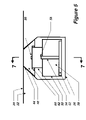
- FIG. 8 shows an example application of an electric machine incorporating the present invention.
- FIG. 9 is similar to FIG. 4 , showing an alternate configuration for the invention.
- FIG. 1 shows a typical permanent magnet (PM) machine 100 according to the prior art, which has a rotor 102 , with permanent magnets 104 mounted thereto by a retaining ring 106 , which is mounted on a rotatable shaft 108 .
- Rotor 102 is adjacent a stator 110 having a plurality of windings 112 interspersed between a plurality of teeth 114 mounted to a back iron 116 .
- An “inside rotor” configuration is shown in FIG. 1 , but the positions of the rotor and stator may also be reversed.
- PM machine 100 may operate in a generator/alternator mode or a motor mode.
- an external torque source forces rotation of the shaft (and thus the rotor and the magnets), and the interaction of the magnets and the windings causes a magnetic flux to loop the windings in the slots.
- the magnetic flux in the stator structure changes, and this changing flux results in generation of voltage in the windings, which results in an output current that can be used to power electrical devices, or be stored for later use.
- FIG. 2 shows an electric machine 10 , generally similar to machine 100 , is shown schematically with the rotor and stator ‘flattened’ for convenience, having a stator 12 and rotor 14 .
- Rotor 14 has a plurality of permanent magnets 16 and is separated from stator 12 by an rotor air gap 18 .
- Stator 12 has a rotor face surface 20 and includes a plurality of teeth 22 extending from a back iron portion 24 to thereby define a plurality of slots 26 for housing winding or windings 28 .
- stator 12 defines a primary magnetic flux path 30 , for guiding magnetic flux from rotor 12 through teeth 22 and back iron 24 , and around winding(s) 28 .
- Retaining means may be required for magnets 16 , depending on machine design, but for clarity, none are shown here.
- the present invention also includes a ‘gate’ member 40 configured to substantially close, and preferably intimately close, a stator slot gap 42 between adjacent teeth 22 in stator 12 .
- Gate 40 is moveable between at least a first or ‘open’ position ( FIG. 1 ) and a second or ‘closed’ position ( FIG. 2 ), as will be described in more detail below.
- a gate gap 44 separates faces 46 and 48 , which are preferably mating faces.
- gate 40 and teeth 22 form a second path 32 which may be used to guide magnetic flux through stator 12 , as will be described in more detail below.
- control means for determining when the gate is to be actuated for movement between its open and closed positions preferably includes a fault sensor, such as an appropriate temperature or current sensor, but may comprise any suitable means of determining when gate 40 is to move, and any suitable means for signaling, releasing or activating a movement mechanism for gate 40 .
- the Machine 10 is preferably generally constructed of known materials.
- the gate member 40 is manufactured preferably from a high magnetic permeability material such as silicon iron or similar suitable materials common to the industry.
- the gate material is preferably of lower reluctance (or higher permeability) material than the material forming the primary magnetic path in the stator, thereby optimizing the functioning of the invention as described in more detail below.
- the gate In use, under ‘normal’ machine operating conditions (i.e. rotor 14 id driven for the purpose of generating electricity using machine 10 ), the gate is positioned in its ‘open’ position (i.e. FIG. 2 ) and, when there, preferably has a negligible effect on the operation of machine 10 .
- rotor 12 passes adjacent stator 12 , magnetic flux from magnets 16 is guided down tooth/teeth 22 , through back iron 24 and back up tooth/teeth 22 to a successive magnet 14 , and thus magnetic flux circulates along primary magnetic circuit path 30 , around windings 28 , and thereby induces voltage in windings 28 which may be used to generate an output current from windings 28 and, as well, machine 10 .
- gate 40 upon the appropriate condition (e.g. upon reaching a threshold temperature, or upon receiving the appropriate command from a sensor sensing an internal fault condition, etc.), gate 40 is moved upward and into contact with the stator teeth 22 , and preferably contact is intimate along faces 46 and 48 , thereby substantially completely closing gate gap 44 and, thereby, slot gap 42 .
- Gate 40 thus forms a new, second magnetic circuit path 32 for guiding magnetic flux in the stator. Since the second flux path 32 preferably has a lower reluctance than the primary magnetic circuit path 30 (i.e. it is an ‘easier’ path for the magnetic flux to follow), the majority of the magnetic flux will bypass the generating path 30 and the windings 28 when the gate is in the ‘closed’ position.
- gate 40 when the gate 40 is closed, magnetic flux in the stator will be guided such there is preferably no or negligible voltage induced in windings 28 .
- the machine 10 may be in this manner ‘shut down’ or ‘turned down’ to control the machine 10 in specific circumstances, such as an internal fault or short circuit in a winding 28 , or another fault such as over-heating in the machine, etc.
- gates 40 are individually closeable, to thereby permit a selective activation of the gate elements of the present invention. In this manner, specifically located internal faults in the machine may be individually isolated without substantially disrupting the normal operation of the remainder of the machine.
- the present invention provides for a shutdown capability which may be activated in a much faster way than the prior art, and need not be activated by temperature or the exceedance of a threshold current. It could be activated for any control purposes, and may even be manually (i.e. non-automatically) actuated, if desired.
- the gate is preferably a wedge-shaped component, as depicted, but need not necessarily be so.
- the faces 46 and 48 may be stepped, curvilinear or straight, and are preferably intimately mating to reduce the overall reluctance of the secondary path.
- the gate 40 is preferably located in the slot of the stator assembly when in its ‘open’ position but, again, but need not necessarily be so.
- a benefit of the present invention is that, when the gate is in the ‘closed’ position, the machine windings become encircled by a relatively high permeability material, which has the effect of multiplying the ‘self’ or ‘leakage’ inductance of the winding which, in turn, causes a significant increase in the impedance of the winding. This thereby beneficially significantly reduces the short circuit current value in the machine winding, adding yet another element of increased safety to the machine.
- the present invention has many applications and is particularly suited to, among many other things, use in an electric machine 10 used as an starter/generator in an aircraft prime mover gas turbine engine 70 (see FIG. 8 ).
- FIGS. 4-7 an apparatus for automatically actuating the present invention is shown.
- gate 40 is supported on winding 28 , in this case a single copper conductor, which thereby also forms a support 50 and pinned to support plate 52 by a plurality of pins 54 .
- Gate 40 is held to pins 54 in a slot 56 and brazed therein by a braze 58 selected and configured to melt above a chosen temperature limit to thereby permit automatic deployment (as described below) of gate 40 once the threshold temperature is exceeded.
- An example of suitable alloy for braze 58 is a gold eutectic alloy with a melting range of 600° F. to 625° F.
- a slot 60 is provided between gate 40 and support 50 for retaining a leaf spring 62 , which is preferably slidably mounted to support 50 by a pin 64 . (The arrow I indicates the direction of current flow through the winding 28 ).
- braze joint 58 in use, when the machine heats up (e.g. due to local or general short circuit current in the windings, or an unwanted over-temperature situation), braze joint 58 will melt thereby releasing pins 54 from slots 56 .
- Support 50 preferably also helps conduct heat in machine 10 to braze joint 58 so that the joint is in good thermal communication with at least the stator slot.
- Spring 62 thereby biases gate 40 towards its ‘closed’ position to close gate 40 as desired.
- spring 62 will move gate 40 at least about 0.060′′, to thereby permit the ‘open’ position of gate 40 to be sufficiently far away from teeth 22 (i.e.
- the leaf spring stiffness is chosen, among other things, to overcome the surface tension of the melted braze to ensure release and movement of gate 40 . Once release, gate 40 will also naturally be attracted to the teeth 22 of the stator 12 due to the action of the magnetic flux from the rotor 14 .
- the braze release mechanism of the present invention is actuated by the heating of winding 28 /support 50 before the risk of fire or significant damage to machine 10 occurs.
- the independent nature of this particular actuation means for gate 40 makes it possible for one phase conductor (i.e. the winding in one slot) to have actuated gate 40 while the remaining phases (i.e. slots) are not shutdown (i.e. some useful power is still produced).
- the motion of the gate can be achieved in a number of different ways.
- support 50 itself may thermally expands sufficiently to close the gate gap 44 .
- another type of spring or other biasing means may be provided.
- the motion required between the ‘open’ and ‘closed’ positions of the gate may be as small as about 0.060′′, depending on the machine design, but may be smaller or larger, as will be understood by the skilled person in light of a review of this disclosure.
- the machine may be single or multi-phase, single or multi-channel.
- the windings may have single or multi turns per slot.
- a variety of winding types may be used (squirrel cage, lap, etc.), and the windings may be any conductor(s) (i.e. single conductor, more than one wire, insulated, laminated, etc.) or may be superconductors.
- the winding(s) 28 need not be integral with the mechanism support structure 50 , but may be separate features as shown in FIG.
- the rotor can be electromagnetic (i.e. permanent magnet not necessary), and may be provided in an outside or inside configuration, or any other suitable configuration.
Abstract
Description
Claims (21)
Priority Applications (6)
| Application Number | Priority Date | Filing Date | Title |
|---|---|---|---|
| US10/461,356 US7253548B2 (en) | 2003-06-16 | 2003-06-16 | Method and apparatus for controlling an electric machine |
| EP04731865A EP1634361A1 (en) | 2003-06-16 | 2004-05-10 | Method and apparatus for controlling an electric machine |
| JP2006515573A JP2006527977A (en) | 2003-06-16 | 2004-05-10 | Control method and apparatus for electric machine |
| CA2527714A CA2527714C (en) | 2003-06-16 | 2004-05-10 | Method and apparatus for controlling an electric machine |
| PCT/CA2004/000690 WO2004112221A1 (en) | 2003-06-16 | 2004-05-10 | Method and apparatus for controlling an electric machine |
| US11/769,915 US7443070B2 (en) | 2003-06-16 | 2007-06-28 | Method and apparatus for controlling an electric machine |
Applications Claiming Priority (1)
| Application Number | Priority Date | Filing Date | Title |
|---|---|---|---|
| US10/461,356 US7253548B2 (en) | 2003-06-16 | 2003-06-16 | Method and apparatus for controlling an electric machine |
Related Child Applications (1)
| Application Number | Title | Priority Date | Filing Date |
|---|---|---|---|
| US11/769,915 Division US7443070B2 (en) | 2003-06-16 | 2007-06-28 | Method and apparatus for controlling an electric machine |
Publications (2)
| Publication Number | Publication Date |
|---|---|
| US20040251765A1 US20040251765A1 (en) | 2004-12-16 |
| US7253548B2 true US7253548B2 (en) | 2007-08-07 |
Family
ID=33511239
Family Applications (2)
| Application Number | Title | Priority Date | Filing Date |
|---|---|---|---|
| US10/461,356 Active 2024-07-11 US7253548B2 (en) | 2003-06-16 | 2003-06-16 | Method and apparatus for controlling an electric machine |
| US11/769,915 Expired - Lifetime US7443070B2 (en) | 2003-06-16 | 2007-06-28 | Method and apparatus for controlling an electric machine |
Family Applications After (1)
| Application Number | Title | Priority Date | Filing Date |
|---|---|---|---|
| US11/769,915 Expired - Lifetime US7443070B2 (en) | 2003-06-16 | 2007-06-28 | Method and apparatus for controlling an electric machine |
Country Status (5)
| Country | Link |
|---|---|
| US (2) | US7253548B2 (en) |
| EP (1) | EP1634361A1 (en) |
| JP (1) | JP2006527977A (en) |
| CA (1) | CA2527714C (en) |
| WO (1) | WO2004112221A1 (en) |
Cited By (2)
| Publication number | Priority date | Publication date | Assignee | Title |
|---|---|---|---|---|
| US11606011B2 (en) | 2020-08-10 | 2023-03-14 | General Electric Company | Electric machine |
| US11894738B2 (en) | 2020-08-31 | 2024-02-06 | General Electric Company | Turbomachine equipped with an embedded electric machine having a segmented and movable stator |
Families Citing this family (19)
| Publication number | Priority date | Publication date | Assignee | Title |
|---|---|---|---|---|
| DE102005016257B4 (en) * | 2005-04-08 | 2008-03-13 | Siemens Ag | reluctance motor |
| US7755242B2 (en) * | 2005-12-05 | 2010-07-13 | Lg Electronics Inc. | Motor, method for manufacturing the same, and washing machine using the same |
| US7541705B2 (en) * | 2007-03-28 | 2009-06-02 | General Electric Company | Fault-tolerant permanent magnet machine with reconfigurable flux paths in stator back iron |
| US7605503B2 (en) * | 2007-03-28 | 2009-10-20 | General Electric Company | Fault-tolerant permanent magnet machine with reconfigurable stator core slot opening and back iron flux paths |
| US7605504B2 (en) * | 2007-03-28 | 2009-10-20 | General Electric Company | Fault-tolerant permanent magnet machine with reconfigurable stator core slot flux paths |
| WO2009013934A1 (en) * | 2007-07-26 | 2009-01-29 | Kura Laboratory Corporation | Flux shunt control rotary electric machine system |
| EP2210207A2 (en) | 2007-10-02 | 2010-07-28 | Nxp B.V. | Multilevel timestamp detection circuit and method |
| US8040007B2 (en) * | 2008-07-28 | 2011-10-18 | Direct Drive Systems, Inc. | Rotor for electric machine having a sleeve with segmented layers |
| US8278858B2 (en) | 2011-01-19 | 2012-10-02 | Hamilton Sundstrand Corporation | Flux cancellation in a permanent magnet generator |
| GB2494166B (en) * | 2011-08-31 | 2018-12-26 | Cummins Generator Technologies | Reducing fault current in a electrical generator |
| JP6323012B2 (en) * | 2014-01-09 | 2018-05-16 | 株式会社ジェイテクト | Rotating electrical machine and control device for rotating electrical machine |
| US9979248B2 (en) | 2015-06-29 | 2018-05-22 | General Electric Company | Short circuit fault tolerant permanent magnet machine |
| US9765850B2 (en) | 2015-10-13 | 2017-09-19 | Goodrich Corporation | Saturation-controlled variable damper systems and methods |
| US9732817B2 (en) | 2015-10-13 | 2017-08-15 | Goodrich Corporation | Axial engagement-controlled variable damper systems and methods |
| WO2017220560A1 (en) * | 2016-06-21 | 2017-12-28 | Bombardier Transportation Gmbh | An electric machine |
| GB201715540D0 (en) * | 2017-09-26 | 2017-11-08 | Rolls Royce Plc | Permanent magnet electrical machine |
| GB201718452D0 (en) * | 2017-11-08 | 2017-12-20 | Rolls Royce Plc | Permanent magnet electrical machine |
| DE102018208686A1 (en) * | 2018-06-01 | 2019-12-05 | Siemens Aktiengesellschaft | Electric machine and hybrid electric aircraft |
| KR20210085589A (en) | 2019-12-31 | 2021-07-08 | 엘지전자 주식회사 | Motor and electric vehicle including the same |
Citations (118)
| Publication number | Priority date | Publication date | Assignee | Title |
|---|---|---|---|---|
| US263136A (en) * | 1882-08-22 | edison | ||
| US819933A (en) * | 1906-05-08 | Charles Prosper Eugene Schneider | Regulation or control of dynamo-electric machines or electric motors. | |
| US1979665A (en) * | 1933-07-26 | 1934-11-06 | Westinghouse Electric & Mfg Co | Dynamo-electric machine |
| US2057471A (en) * | 1935-08-15 | 1936-10-13 | Westinghouse Electric & Mfg Co | Dynamo-electric machine |
| US2058339A (en) * | 1935-09-12 | 1936-10-20 | Gen Electric | Dynamo-electric machine |
| US2227678A (en) * | 1938-02-23 | 1941-01-07 | Edgar G Stiles | Arc welder |
| US2264272A (en) * | 1939-06-23 | 1941-12-02 | Westinghouse Electric & Mfg Co | Welding generator |
| US2287929A (en) * | 1939-06-23 | 1942-06-30 | Westinghouse Electric & Mfg Co | Motor-generator set and generator |
| US2300867A (en) * | 1941-07-24 | 1942-11-03 | Westinghouse Electric & Mfg Co | Welding generator |
| US2378894A (en) * | 1943-07-24 | 1945-06-26 | Westinghouse Electric Corp | Generator |
| US2482526A (en) * | 1945-07-09 | 1949-09-20 | Westinghouse Electric Corp | Dynamoelectric machine |
| US2610993A (en) * | 1951-07-12 | 1952-09-16 | Gen Electric | Adjustable magnetic shunt for permanent magnet generators |
| US2807772A (en) * | 1954-08-27 | 1957-09-24 | Melentine Albert | Generator control by adjustable magnetic shunt |
| FR1555855A (en) | 1967-12-20 | 1969-01-31 | ||
| US3612929A (en) * | 1968-09-26 | 1971-10-12 | Siemens Ag | Device for temperature compensation in electrical machines excited by permanent magnets |
| US3673490A (en) | 1970-09-29 | 1972-06-27 | Phelon Co Inc | Combined alternator and ignition trigger signal generator with arrangement for suppressing spurious trigger signals |
| US3707638A (en) | 1970-03-09 | 1972-12-26 | Alumina Ferrite Corp | Electric motor utilizing a ferrite stator of low coerciveness, ferrite rotor of high coerciveness, and photo-electric commutation |
| US3753068A (en) | 1971-11-09 | 1973-08-14 | Electro Craft Corp | Controlled speed electric motor |
| US3812441A (en) | 1971-12-03 | 1974-05-21 | Nippon Automation Kk | Reed switch mechanism making use of heat-sensitive ferrite |
| US3961211A (en) | 1974-01-15 | 1976-06-01 | Crouzet | Gyroscope motor |
| US4004202A (en) | 1975-01-29 | 1977-01-18 | Imc Magnetics Corporation | Brushless D.C. motor |
| US4025840A (en) * | 1975-04-09 | 1977-05-24 | General Electric Company | Permanent magnet generator with output power adjustment by means of magnetic shims |
| US4032807A (en) | 1976-01-06 | 1977-06-28 | General Electric Company | Inside-out motor/alternator with high inertia smooth rotor |
| US4039910A (en) | 1973-09-10 | 1977-08-02 | The Garrett Corporation | Dynamoelectric machine |
| US4186366A (en) | 1978-10-20 | 1980-01-29 | Illinois Tool Works Inc. | Radial lead thermal cut-off device |
| US4190794A (en) * | 1978-03-20 | 1980-02-26 | Kreso Mikulic | Alternating current motor with adjustable output torque by means of adjustable magnetic bars |
| US4237395A (en) | 1978-10-30 | 1980-12-02 | Loudermilk Billy E | Electric dynamotor |
| EP0022379A1 (en) | 1979-07-05 | 1981-01-14 | The Bendix Corporation | Permanent magnet generator |
| US4250128A (en) | 1975-01-29 | 1981-02-10 | Magna Motors Corporation | Processes and apparatuses for preparing permanent magnet stators |
| US4346335A (en) | 1981-04-07 | 1982-08-24 | Mcinnis Stirling A | Speed control of a D.C. electric motor |
| US4392072A (en) | 1978-09-13 | 1983-07-05 | General Electric Company | Dynamoelectric machine stator having articulated amorphous metal components |
| US4401906A (en) | 1980-03-17 | 1983-08-30 | Oki Electric Industry Co., Ltd. | Motor with improved temperature characteristics |
| US4445061A (en) | 1980-06-17 | 1984-04-24 | Synetron Corporation | Wide air gap permanent magnet motors |
| US4492902A (en) | 1983-06-03 | 1985-01-08 | Allied Corporation | Permanent magnetic motor common leg impedance compensation means |
| US4503377A (en) | 1983-01-14 | 1985-03-05 | Hitachi, Ltd. | Variable speed rotary electric machine |
| US4511831A (en) | 1981-04-07 | 1985-04-16 | Mcinnis Stirling A | Speed control of a D.C. electric motor |
| US4547713A (en) | 1982-11-05 | 1985-10-15 | Kollmorgen Technologies Corporation | Toroidally wound brushless DC motor |
| US4562399A (en) | 1983-06-14 | 1985-12-31 | Kollmorgen Technologies Corporation | Brushless DC tachometer |
| US4605874A (en) | 1984-06-12 | 1986-08-12 | Maghemite Inc. | Brushless D.C. dynamoelectric machine having ferrite material magnetic circuit |
| US4617726A (en) | 1984-12-06 | 1986-10-21 | The Garrett Corporation | Maximum stiffness permanent magnet rotor and construction method |
| US4625135A (en) | 1983-07-19 | 1986-11-25 | The Garrett Corporation | Permanent magnet rotor |
| US4638201A (en) | 1983-05-20 | 1987-01-20 | Standard Elektrik Lorenz Aktiengesellschaft | Electronically commutated dc motor |
| US4641080A (en) * | 1984-10-18 | 1987-02-03 | Sundstrand Corporation | Permanent magnet generator with fault detection |
| US4681729A (en) | 1984-05-21 | 1987-07-21 | National Nuclear Corporation Limited | Monitoring temperature within a vessel |
| US4694654A (en) * | 1983-10-29 | 1987-09-22 | Isuzu Motors Limited | Exhaust energy recovery and generator for use with an engine |
| US4709180A (en) | 1985-11-20 | 1987-11-24 | The Garrett Corporation | Toothless stator construction for electrical machines |
| US4763034A (en) | 1987-07-10 | 1988-08-09 | Sigma Instruments, Inc. | Magnetically enhanced stepping motor |
| US4799578A (en) | 1986-02-03 | 1989-01-24 | Sanden Corporation | Apparatus for preventing heat damage in an electromagnetic clutch |
| FR2618616A1 (en) | 1987-07-20 | 1989-01-27 | Sobiepanek Janusz | Electric machine with high drive and/or positioning torque |
| US4852245A (en) | 1985-11-20 | 1989-08-01 | Allied-Signal Inc. | Toothless stator electrical machine construction method |
| US4885493A (en) | 1988-07-25 | 1989-12-05 | General Motors Corporation | Output voltage control apparatus of a permanent magnet alternator |
| US4887020A (en) | 1984-07-23 | 1989-12-12 | U.S. Philips Corporation | Self-compensating brushless alternator |
| US4897570A (en) | 1987-02-12 | 1990-01-30 | Nissan Motor Co., Ltd. | Starter motor for automitove engine |
| US4924125A (en) | 1987-09-15 | 1990-05-08 | Clark Automotive Developments Limited | Electric motor or alternator |
| EP0368930A1 (en) | 1987-09-15 | 1990-05-23 | Cadac Holdings Ltd | A motor or alternator. |
| US4929922A (en) | 1987-12-24 | 1990-05-29 | Inter Control Hermann Kohler Elektrik Gmbh | Temperature safety device for electric devices |
| JPH03107343A (en) * | 1989-09-21 | 1991-05-07 | Toshiba Corp | Fixing structure of rotary electric machine |
| US5015905A (en) * | 1988-05-27 | 1991-05-14 | Hitachi, Ltd. | DC dynamoelectric machine with interpoles having magnetic flux bypassing members |
| US5030877A (en) | 1985-11-20 | 1991-07-09 | Allied-Signal Inc. | Turbine engine with integral clam shell dynamoelectric machine |
| US5184040A (en) | 1989-09-04 | 1993-02-02 | Lim Jong H | Electric power generators having like numbers of magnets and coils |
| US5235231A (en) | 1991-04-12 | 1993-08-10 | Hisey Bradner L | Dynamoelectric machines having energy-efficient stator constructions and method |
| US5304883A (en) | 1992-09-03 | 1994-04-19 | Alliedsignal Inc | Ring wound stator having variable cross section conductors |
| US5397948A (en) | 1993-03-12 | 1995-03-14 | Nartron Corporation | Magnetic motor with temperature related activation |
| JPH07123621A (en) | 1993-10-21 | 1995-05-12 | Hitachi Ltd | Turbine generator |
| US5430362A (en) * | 1993-05-12 | 1995-07-04 | Sundstrand Corporation | Engine starting system utilizing multiple controlled acceleration rates |
| US5519275A (en) | 1994-03-18 | 1996-05-21 | Coleman Powermate, Inc. | Electric machine with a transformer having a rotating component |
| US5555722A (en) | 1993-11-15 | 1996-09-17 | Sundstrand Corporation | Integrated APU |
| US5585682A (en) | 1993-11-10 | 1996-12-17 | Sundstrand Corporation | Thermally compensated assembly for a generator |
| EP0750806A1 (en) | 1994-03-17 | 1997-01-02 | AlliedSignal Inc. | Electrical machines and components thereof incorporating foil journal bearings |
| EP0754365A1 (en) | 1993-12-15 | 1997-01-22 | AlliedSignal Inc. | Redundant electric motor arrangement including single rotor assembly having two magnet sections |
| US5737164A (en) * | 1996-07-11 | 1998-04-07 | Sundstrand Corporation | Switched reluctance machine capable of improved fault operation |
| US5742106A (en) | 1995-08-28 | 1998-04-21 | Mikuni Corporation | Thermo-sensitive actuator and idle speed controller employing the same |
| US5770901A (en) | 1995-10-31 | 1998-06-23 | Nippondenso | Starter with overheat protection |
| US5793178A (en) | 1996-01-04 | 1998-08-11 | Thomson-Csf | Synchronous permanent-magnet electric motor and vehicle driven by such a motor |
| US5793137A (en) | 1992-03-04 | 1998-08-11 | Ultra Electronics, Limited | Electrical power generators |
| US5798596A (en) | 1996-07-03 | 1998-08-25 | Pacific Scientific Company | Permanent magnet motor with enhanced inductance |
| US5822150A (en) | 1995-02-22 | 1998-10-13 | Integral Peripherals, Inc. | Disk drive including a substantially monolithic stator assembly fabricated from low loss magnetic material |
| US5825597A (en) | 1996-09-25 | 1998-10-20 | General Electric Company | System and method for detection and control of circulating currents in a motor |
| US5831507A (en) | 1996-09-09 | 1998-11-03 | Toyo System Co., Ltd. | Dual-functional fuse unit that is responsive to electric current and ambient temperature |
| US5834874A (en) | 1997-09-30 | 1998-11-10 | Outboard Marine Corporation | Alternator with mechanically adjustable output |
| US5838080A (en) | 1996-08-29 | 1998-11-17 | Imphy S.A. | Stepper motor for clockwork in which the stator consists of a soft magnetic alloy and soft magnetic alloy |
| EP0881744A2 (en) | 1997-05-26 | 1998-12-02 | Denso Corporation | Alternator for vehicle |
| WO1999009638A1 (en) | 1997-08-13 | 1999-02-25 | Alliedsignal Inc. | Compact hybrid electrical machine |
| US5903115A (en) | 1997-11-24 | 1999-05-11 | Alliedsignal Inc. | Auxiliary system including a plurality of ac motors powered directly by an electric generator |
| US5912522A (en) | 1996-08-22 | 1999-06-15 | Rivera; Nicholas N. | Permanent magnet direct current (PMDC) machine with integral reconfigurable winding control |
| US5917248A (en) | 1995-01-31 | 1999-06-29 | Denso Corporation | System and method for driving electric vehicle |
| US5925999A (en) | 1996-11-13 | 1999-07-20 | Siemens Canada Limited | Three-speed dual-winding direct current permanent magnet motor method and apparatus |
| EP0932246A2 (en) | 1998-01-23 | 1999-07-28 | Kabushiki Kaisha Toshiba | Permanent magnet type electrical rotating machine |
| US5936325A (en) | 1996-12-31 | 1999-08-10 | Valeo Electronique | Synchronous type electrical machine |
| US5953491A (en) | 1997-09-29 | 1999-09-14 | Alliedsignal Inc. | Control system for a permanent magnet motor |
| US5952757A (en) | 1995-12-04 | 1999-09-14 | General Electric Company | Line start permanent magnet motor |
| US5955809A (en) | 1992-08-17 | 1999-09-21 | Intellectual Property Law Department Sundstrand Corporation | Permanent magnet generator with auxiliary winding |
| US5962938A (en) | 1997-10-21 | 1999-10-05 | General Electric Company | Motor with external rotor |
| WO1999066624A1 (en) | 1998-06-18 | 1999-12-23 | Alliedsignal Inc. | Amorphous metal stator for a radial-flux electric motor |
| US6020711A (en) * | 1998-03-05 | 2000-02-01 | The United States Of America As Represented By The Secretary Of The Air Force | Multiple winding channel, magnetic coupling-alterable reluctance electrical machines and their fault tolerant control |
| US6031311A (en) | 1997-11-13 | 2000-02-29 | Samsung Electronics Co., Ltd. | Brushless DC motor capable of preventing leakage of magnetic flux |
| US6097124A (en) | 1997-10-23 | 2000-08-01 | Satcon Technology Corporation | Hybrid permanent magnet/homopolar generator and motor |
| US6100620A (en) | 1996-08-05 | 2000-08-08 | S.H.R. Ltd. Bvi | High frequency synchronous rotary electrical machine |
| US6114784A (en) | 1998-06-22 | 2000-09-05 | Nissan Motor Co., Ltd. | Motor with cooling structure |
| US6239532B1 (en) | 1996-12-05 | 2001-05-29 | General Electric Company | Motor with external rotor |
| US6242840B1 (en) | 1998-06-15 | 2001-06-05 | Alliedsignal Inc. | Electrical machine including toothless flux collector made from ferromagnetic wire |
| US6255756B1 (en) | 1997-12-01 | 2001-07-03 | General Electric Company | Winding arrangement for switched reluctance machine based internal starter generator |
| US6271613B1 (en) | 1998-06-25 | 2001-08-07 | Valeo Equipment Electriques Moteur | Rotating machine, such as motor vehicle alternator |
| US6313560B1 (en) * | 1999-12-20 | 2001-11-06 | Pratt & Whitney Canada Corp. | Thermally protected electric machine |
| US6323625B1 (en) | 1996-12-03 | 2001-11-27 | Brij B. Bhargava | Turbine/alternator on a common shaft with an associated electrical system |
| US6342746B1 (en) | 1998-07-31 | 2002-01-29 | Magnetic Revolutions Limited, L.L.C. | Methods for controlling the path of magnetic flux from a permanent magnet and devices incorporating the same |
| WO2002009260A1 (en) | 2000-07-24 | 2002-01-31 | Newage International Limited | A permanent magnet ac machine |
| US6373162B1 (en) | 1999-11-11 | 2002-04-16 | Ford Global Technologies, Inc. | Permanent magnet electric machine with flux control |
| US20020084715A1 (en) | 2000-12-28 | 2002-07-04 | Tsuyoshi Kakuta | Motor having characteristic structure in armature and disc apparatus |
| US20020084705A1 (en) | 2000-12-28 | 2002-07-04 | Hideo Kawamura | Magnetic flux controls for permanent-magnet motor-generator |
| US20020093252A1 (en) | 2000-12-29 | 2002-07-18 | Korea Electrotechnology Research Institute | Integrated system of a permanent magnet excited motor and a non-contact power feeding apparatus |
| US20020096960A1 (en) | 2000-12-01 | 2002-07-25 | Wei Tong | Generator magnetic armature wedge and method for increasing subtransient reactance of a generator |
| US6429615B2 (en) | 1999-12-08 | 2002-08-06 | Papst Motoren Gmbh & Co. Kg | Electronically commutated DC motor |
| US6437529B1 (en) | 1998-05-04 | 2002-08-20 | Comair Rotron, Inc. | Multi-stator motor with independent stator circuits |
| US20020149281A1 (en) | 2001-04-17 | 2002-10-17 | Moteurs Leroy-Somer | Stator for an electric machine |
| US6504261B2 (en) | 2000-05-16 | 2003-01-07 | General Electric Company | Synchronous generator having auxiliary power windings and variable frequency power source and method for use |
| US6525504B1 (en) | 1997-11-28 | 2003-02-25 | Abb Ab | Method and device for controlling the magnetic flux in a rotating high voltage electric alternating current machine |
| US6541887B2 (en) | 1999-03-12 | 2003-04-01 | Hideo Kawamura | Permanent-magnet motor-generator with voltage stabilizer |
Family Cites Families (1)
| Publication number | Priority date | Publication date | Assignee | Title |
|---|---|---|---|---|
| US4186080A (en) * | 1975-12-22 | 1980-01-29 | Mobil Oil Corporation | Use of catalyst comprising titania and zirconia in hydrotreating |
-
2003
- 2003-06-16 US US10/461,356 patent/US7253548B2/en active Active
-
2004
- 2004-05-10 CA CA2527714A patent/CA2527714C/en not_active Expired - Fee Related
- 2004-05-10 EP EP04731865A patent/EP1634361A1/en not_active Withdrawn
- 2004-05-10 JP JP2006515573A patent/JP2006527977A/en active Pending
- 2004-05-10 WO PCT/CA2004/000690 patent/WO2004112221A1/en active Application Filing
-
2007
- 2007-06-28 US US11/769,915 patent/US7443070B2/en not_active Expired - Lifetime
Patent Citations (123)
| Publication number | Priority date | Publication date | Assignee | Title |
|---|---|---|---|---|
| US263136A (en) * | 1882-08-22 | edison | ||
| US819933A (en) * | 1906-05-08 | Charles Prosper Eugene Schneider | Regulation or control of dynamo-electric machines or electric motors. | |
| US1979665A (en) * | 1933-07-26 | 1934-11-06 | Westinghouse Electric & Mfg Co | Dynamo-electric machine |
| US2057471A (en) * | 1935-08-15 | 1936-10-13 | Westinghouse Electric & Mfg Co | Dynamo-electric machine |
| US2058339A (en) * | 1935-09-12 | 1936-10-20 | Gen Electric | Dynamo-electric machine |
| US2227678A (en) * | 1938-02-23 | 1941-01-07 | Edgar G Stiles | Arc welder |
| US2264272A (en) * | 1939-06-23 | 1941-12-02 | Westinghouse Electric & Mfg Co | Welding generator |
| US2287929A (en) * | 1939-06-23 | 1942-06-30 | Westinghouse Electric & Mfg Co | Motor-generator set and generator |
| US2300867A (en) * | 1941-07-24 | 1942-11-03 | Westinghouse Electric & Mfg Co | Welding generator |
| US2378894A (en) * | 1943-07-24 | 1945-06-26 | Westinghouse Electric Corp | Generator |
| US2482526A (en) * | 1945-07-09 | 1949-09-20 | Westinghouse Electric Corp | Dynamoelectric machine |
| US2610993A (en) * | 1951-07-12 | 1952-09-16 | Gen Electric | Adjustable magnetic shunt for permanent magnet generators |
| US2807772A (en) * | 1954-08-27 | 1957-09-24 | Melentine Albert | Generator control by adjustable magnetic shunt |
| FR1555855A (en) | 1967-12-20 | 1969-01-31 | ||
| US3612929A (en) * | 1968-09-26 | 1971-10-12 | Siemens Ag | Device for temperature compensation in electrical machines excited by permanent magnets |
| US3707638A (en) | 1970-03-09 | 1972-12-26 | Alumina Ferrite Corp | Electric motor utilizing a ferrite stator of low coerciveness, ferrite rotor of high coerciveness, and photo-electric commutation |
| US3673490A (en) | 1970-09-29 | 1972-06-27 | Phelon Co Inc | Combined alternator and ignition trigger signal generator with arrangement for suppressing spurious trigger signals |
| US3753068A (en) | 1971-11-09 | 1973-08-14 | Electro Craft Corp | Controlled speed electric motor |
| US3812441A (en) | 1971-12-03 | 1974-05-21 | Nippon Automation Kk | Reed switch mechanism making use of heat-sensitive ferrite |
| US4039910A (en) | 1973-09-10 | 1977-08-02 | The Garrett Corporation | Dynamoelectric machine |
| US3961211A (en) | 1974-01-15 | 1976-06-01 | Crouzet | Gyroscope motor |
| US4004202A (en) | 1975-01-29 | 1977-01-18 | Imc Magnetics Corporation | Brushless D.C. motor |
| US4250128A (en) | 1975-01-29 | 1981-02-10 | Magna Motors Corporation | Processes and apparatuses for preparing permanent magnet stators |
| US4025840A (en) * | 1975-04-09 | 1977-05-24 | General Electric Company | Permanent magnet generator with output power adjustment by means of magnetic shims |
| US4032807A (en) | 1976-01-06 | 1977-06-28 | General Electric Company | Inside-out motor/alternator with high inertia smooth rotor |
| US4190794A (en) * | 1978-03-20 | 1980-02-26 | Kreso Mikulic | Alternating current motor with adjustable output torque by means of adjustable magnetic bars |
| US4392072A (en) | 1978-09-13 | 1983-07-05 | General Electric Company | Dynamoelectric machine stator having articulated amorphous metal components |
| US4186366A (en) | 1978-10-20 | 1980-01-29 | Illinois Tool Works Inc. | Radial lead thermal cut-off device |
| US4237395A (en) | 1978-10-30 | 1980-12-02 | Loudermilk Billy E | Electric dynamotor |
| EP0022379A1 (en) | 1979-07-05 | 1981-01-14 | The Bendix Corporation | Permanent magnet generator |
| US4401906A (en) | 1980-03-17 | 1983-08-30 | Oki Electric Industry Co., Ltd. | Motor with improved temperature characteristics |
| US4445061A (en) | 1980-06-17 | 1984-04-24 | Synetron Corporation | Wide air gap permanent magnet motors |
| US4511831A (en) | 1981-04-07 | 1985-04-16 | Mcinnis Stirling A | Speed control of a D.C. electric motor |
| US4346335A (en) | 1981-04-07 | 1982-08-24 | Mcinnis Stirling A | Speed control of a D.C. electric motor |
| US4547713A (en) | 1982-11-05 | 1985-10-15 | Kollmorgen Technologies Corporation | Toroidally wound brushless DC motor |
| US4503377A (en) | 1983-01-14 | 1985-03-05 | Hitachi, Ltd. | Variable speed rotary electric machine |
| US4638201A (en) | 1983-05-20 | 1987-01-20 | Standard Elektrik Lorenz Aktiengesellschaft | Electronically commutated dc motor |
| US4492902A (en) | 1983-06-03 | 1985-01-08 | Allied Corporation | Permanent magnetic motor common leg impedance compensation means |
| US4562399A (en) | 1983-06-14 | 1985-12-31 | Kollmorgen Technologies Corporation | Brushless DC tachometer |
| US4625135A (en) | 1983-07-19 | 1986-11-25 | The Garrett Corporation | Permanent magnet rotor |
| US4694654A (en) * | 1983-10-29 | 1987-09-22 | Isuzu Motors Limited | Exhaust energy recovery and generator for use with an engine |
| US4681729A (en) | 1984-05-21 | 1987-07-21 | National Nuclear Corporation Limited | Monitoring temperature within a vessel |
| US4605874A (en) | 1984-06-12 | 1986-08-12 | Maghemite Inc. | Brushless D.C. dynamoelectric machine having ferrite material magnetic circuit |
| US4887020A (en) | 1984-07-23 | 1989-12-12 | U.S. Philips Corporation | Self-compensating brushless alternator |
| US4641080A (en) * | 1984-10-18 | 1987-02-03 | Sundstrand Corporation | Permanent magnet generator with fault detection |
| US4617726A (en) | 1984-12-06 | 1986-10-21 | The Garrett Corporation | Maximum stiffness permanent magnet rotor and construction method |
| US4852245A (en) | 1985-11-20 | 1989-08-01 | Allied-Signal Inc. | Toothless stator electrical machine construction method |
| US4709180A (en) | 1985-11-20 | 1987-11-24 | The Garrett Corporation | Toothless stator construction for electrical machines |
| US5030877A (en) | 1985-11-20 | 1991-07-09 | Allied-Signal Inc. | Turbine engine with integral clam shell dynamoelectric machine |
| US4799578A (en) | 1986-02-03 | 1989-01-24 | Sanden Corporation | Apparatus for preventing heat damage in an electromagnetic clutch |
| US4896756A (en) | 1986-02-03 | 1990-01-30 | Sanden Corporation | Apparatus for preventing heat damage in an electromagnetic clutch |
| US4897570A (en) | 1987-02-12 | 1990-01-30 | Nissan Motor Co., Ltd. | Starter motor for automitove engine |
| US4763034A (en) | 1987-07-10 | 1988-08-09 | Sigma Instruments, Inc. | Magnetically enhanced stepping motor |
| FR2618616A1 (en) | 1987-07-20 | 1989-01-27 | Sobiepanek Janusz | Electric machine with high drive and/or positioning torque |
| US4924125A (en) | 1987-09-15 | 1990-05-08 | Clark Automotive Developments Limited | Electric motor or alternator |
| EP0368930A1 (en) | 1987-09-15 | 1990-05-23 | Cadac Holdings Ltd | A motor or alternator. |
| US4929922A (en) | 1987-12-24 | 1990-05-29 | Inter Control Hermann Kohler Elektrik Gmbh | Temperature safety device for electric devices |
| US5015905A (en) * | 1988-05-27 | 1991-05-14 | Hitachi, Ltd. | DC dynamoelectric machine with interpoles having magnetic flux bypassing members |
| US4885493A (en) | 1988-07-25 | 1989-12-05 | General Motors Corporation | Output voltage control apparatus of a permanent magnet alternator |
| US5184040A (en) | 1989-09-04 | 1993-02-02 | Lim Jong H | Electric power generators having like numbers of magnets and coils |
| JPH03107343A (en) * | 1989-09-21 | 1991-05-07 | Toshiba Corp | Fixing structure of rotary electric machine |
| US5235231A (en) | 1991-04-12 | 1993-08-10 | Hisey Bradner L | Dynamoelectric machines having energy-efficient stator constructions and method |
| US5793137A (en) | 1992-03-04 | 1998-08-11 | Ultra Electronics, Limited | Electrical power generators |
| US5955809A (en) | 1992-08-17 | 1999-09-21 | Intellectual Property Law Department Sundstrand Corporation | Permanent magnet generator with auxiliary winding |
| US5304883A (en) | 1992-09-03 | 1994-04-19 | Alliedsignal Inc | Ring wound stator having variable cross section conductors |
| US5397948A (en) | 1993-03-12 | 1995-03-14 | Nartron Corporation | Magnetic motor with temperature related activation |
| US5430362A (en) * | 1993-05-12 | 1995-07-04 | Sundstrand Corporation | Engine starting system utilizing multiple controlled acceleration rates |
| JPH07123621A (en) | 1993-10-21 | 1995-05-12 | Hitachi Ltd | Turbine generator |
| US5585682A (en) | 1993-11-10 | 1996-12-17 | Sundstrand Corporation | Thermally compensated assembly for a generator |
| US5555722A (en) | 1993-11-15 | 1996-09-17 | Sundstrand Corporation | Integrated APU |
| EP0754365A1 (en) | 1993-12-15 | 1997-01-22 | AlliedSignal Inc. | Redundant electric motor arrangement including single rotor assembly having two magnet sections |
| EP0750806A1 (en) | 1994-03-17 | 1997-01-02 | AlliedSignal Inc. | Electrical machines and components thereof incorporating foil journal bearings |
| US5519275A (en) | 1994-03-18 | 1996-05-21 | Coleman Powermate, Inc. | Electric machine with a transformer having a rotating component |
| US5917248A (en) | 1995-01-31 | 1999-06-29 | Denso Corporation | System and method for driving electric vehicle |
| US5822150A (en) | 1995-02-22 | 1998-10-13 | Integral Peripherals, Inc. | Disk drive including a substantially monolithic stator assembly fabricated from low loss magnetic material |
| US5742106A (en) | 1995-08-28 | 1998-04-21 | Mikuni Corporation | Thermo-sensitive actuator and idle speed controller employing the same |
| US5770901A (en) | 1995-10-31 | 1998-06-23 | Nippondenso | Starter with overheat protection |
| US5952757A (en) | 1995-12-04 | 1999-09-14 | General Electric Company | Line start permanent magnet motor |
| US5793178A (en) | 1996-01-04 | 1998-08-11 | Thomson-Csf | Synchronous permanent-magnet electric motor and vehicle driven by such a motor |
| US5798596A (en) | 1996-07-03 | 1998-08-25 | Pacific Scientific Company | Permanent magnet motor with enhanced inductance |
| US5737164A (en) * | 1996-07-11 | 1998-04-07 | Sundstrand Corporation | Switched reluctance machine capable of improved fault operation |
| US6100620A (en) | 1996-08-05 | 2000-08-08 | S.H.R. Ltd. Bvi | High frequency synchronous rotary electrical machine |
| US5912522A (en) | 1996-08-22 | 1999-06-15 | Rivera; Nicholas N. | Permanent magnet direct current (PMDC) machine with integral reconfigurable winding control |
| US5838080A (en) | 1996-08-29 | 1998-11-17 | Imphy S.A. | Stepper motor for clockwork in which the stator consists of a soft magnetic alloy and soft magnetic alloy |
| US5831507A (en) | 1996-09-09 | 1998-11-03 | Toyo System Co., Ltd. | Dual-functional fuse unit that is responsive to electric current and ambient temperature |
| US5825597A (en) | 1996-09-25 | 1998-10-20 | General Electric Company | System and method for detection and control of circulating currents in a motor |
| US5925999A (en) | 1996-11-13 | 1999-07-20 | Siemens Canada Limited | Three-speed dual-winding direct current permanent magnet motor method and apparatus |
| US6323625B1 (en) | 1996-12-03 | 2001-11-27 | Brij B. Bhargava | Turbine/alternator on a common shaft with an associated electrical system |
| US6239532B1 (en) | 1996-12-05 | 2001-05-29 | General Electric Company | Motor with external rotor |
| US5936325A (en) | 1996-12-31 | 1999-08-10 | Valeo Electronique | Synchronous type electrical machine |
| EP0881744A2 (en) | 1997-05-26 | 1998-12-02 | Denso Corporation | Alternator for vehicle |
| US5942829A (en) | 1997-08-13 | 1999-08-24 | Alliedsignal Inc. | Hybrid electrical machine including homopolar rotor and stator therefor |
| WO1999009638A1 (en) | 1997-08-13 | 1999-02-25 | Alliedsignal Inc. | Compact hybrid electrical machine |
| US5953491A (en) | 1997-09-29 | 1999-09-14 | Alliedsignal Inc. | Control system for a permanent magnet motor |
| US5834874A (en) | 1997-09-30 | 1998-11-10 | Outboard Marine Corporation | Alternator with mechanically adjustable output |
| US5962938A (en) | 1997-10-21 | 1999-10-05 | General Electric Company | Motor with external rotor |
| US6286199B1 (en) | 1997-10-21 | 2001-09-11 | General Electric Company | Method for assembly of motor with external rotor |
| US6097124A (en) | 1997-10-23 | 2000-08-01 | Satcon Technology Corporation | Hybrid permanent magnet/homopolar generator and motor |
| US6031311A (en) | 1997-11-13 | 2000-02-29 | Samsung Electronics Co., Ltd. | Brushless DC motor capable of preventing leakage of magnetic flux |
| US5903115A (en) | 1997-11-24 | 1999-05-11 | Alliedsignal Inc. | Auxiliary system including a plurality of ac motors powered directly by an electric generator |
| US6525504B1 (en) | 1997-11-28 | 2003-02-25 | Abb Ab | Method and device for controlling the magnetic flux in a rotating high voltage electric alternating current machine |
| US6255756B1 (en) | 1997-12-01 | 2001-07-03 | General Electric Company | Winding arrangement for switched reluctance machine based internal starter generator |
| EP0932246A2 (en) | 1998-01-23 | 1999-07-28 | Kabushiki Kaisha Toshiba | Permanent magnet type electrical rotating machine |
| US6265801B1 (en) | 1998-01-23 | 2001-07-24 | Kabushiki Kaisha Toshiba | Permanent magnet type electrical rotating machine |
| US6020711A (en) * | 1998-03-05 | 2000-02-01 | The United States Of America As Represented By The Secretary Of The Air Force | Multiple winding channel, magnetic coupling-alterable reluctance electrical machines and their fault tolerant control |
| US6437529B1 (en) | 1998-05-04 | 2002-08-20 | Comair Rotron, Inc. | Multi-stator motor with independent stator circuits |
| US6242840B1 (en) | 1998-06-15 | 2001-06-05 | Alliedsignal Inc. | Electrical machine including toothless flux collector made from ferromagnetic wire |
| WO1999066624A1 (en) | 1998-06-18 | 1999-12-23 | Alliedsignal Inc. | Amorphous metal stator for a radial-flux electric motor |
| US6114784A (en) | 1998-06-22 | 2000-09-05 | Nissan Motor Co., Ltd. | Motor with cooling structure |
| US6271613B1 (en) | 1998-06-25 | 2001-08-07 | Valeo Equipment Electriques Moteur | Rotating machine, such as motor vehicle alternator |
| US6342746B1 (en) | 1998-07-31 | 2002-01-29 | Magnetic Revolutions Limited, L.L.C. | Methods for controlling the path of magnetic flux from a permanent magnet and devices incorporating the same |
| US6541887B2 (en) | 1999-03-12 | 2003-04-01 | Hideo Kawamura | Permanent-magnet motor-generator with voltage stabilizer |
| US6373162B1 (en) | 1999-11-11 | 2002-04-16 | Ford Global Technologies, Inc. | Permanent magnet electric machine with flux control |
| US6429615B2 (en) | 1999-12-08 | 2002-08-06 | Papst Motoren Gmbh & Co. Kg | Electronically commutated DC motor |
| US20020047477A1 (en) | 1999-12-20 | 2002-04-25 | Dooley Kevin Allan | Method of providing electric power with thermal protection |
| US6313560B1 (en) * | 1999-12-20 | 2001-11-06 | Pratt & Whitney Canada Corp. | Thermally protected electric machine |
| US6504261B2 (en) | 2000-05-16 | 2003-01-07 | General Electric Company | Synchronous generator having auxiliary power windings and variable frequency power source and method for use |
| WO2002009260A1 (en) | 2000-07-24 | 2002-01-31 | Newage International Limited | A permanent magnet ac machine |
| US20020096960A1 (en) | 2000-12-01 | 2002-07-25 | Wei Tong | Generator magnetic armature wedge and method for increasing subtransient reactance of a generator |
| US20020084705A1 (en) | 2000-12-28 | 2002-07-04 | Hideo Kawamura | Magnetic flux controls for permanent-magnet motor-generator |
| US20020084715A1 (en) | 2000-12-28 | 2002-07-04 | Tsuyoshi Kakuta | Motor having characteristic structure in armature and disc apparatus |
| US20020093252A1 (en) | 2000-12-29 | 2002-07-18 | Korea Electrotechnology Research Institute | Integrated system of a permanent magnet excited motor and a non-contact power feeding apparatus |
| US20020149281A1 (en) | 2001-04-17 | 2002-10-17 | Moteurs Leroy-Somer | Stator for an electric machine |
Non-Patent Citations (12)
| Title |
|---|
| B. Dishner et al., "A Novel Electromechanical Approach to Constant Frequency Power Generation", IEEE Journal, 1989. |
| General Electric Company, "150Kva Samarium Cobalt VSCF Starter/Generator Electrical System, Final Technical Report", 1979. |
| M. Cronin, "The All-Electric Airplane as Energy Efficient Transport", SAE Journal, 1980. |
| M. Cronin, "The All-Electric Airplane Revisited", SAE Technical Series, 1989. |
| PCT International Search Report for International application No. PCT/CA2004/000690 mailed Sep. 16, 2004. |
| PCT International Search Report, PCT/CA2004/000408, Mailed Aug. 30, 2004. |
| R. Nims, "Armor-plated auxiliary power", Mechanical Engineering, 1997. |
| R. Nims, "Development of an Oilless, Gearless, and Bleedable Under Armour Power Unit", ASME paper, 1995. |
| Richter, E. et al., "Jet Engine Integrated Generator", Amcn Inst. Aeronautics & Astronautics, 1981. |
| Ricther et al., "Preliminary Design of an Internal Starter/Generator for Application in the F110-129 Engine", SAE Aerospace Atlantic Conference, 1995. |
| SAE Technical Paper Series 892252, Application Considerations for Integral Gas Turbine Electric Starter/Generator revisited. 1989. |
| The Applicability of Electrically Driven Accessories for Turboshaft Engines, 1993. |
Cited By (3)
| Publication number | Priority date | Publication date | Assignee | Title |
|---|---|---|---|---|
| US11606011B2 (en) | 2020-08-10 | 2023-03-14 | General Electric Company | Electric machine |
| US20230396139A1 (en) * | 2020-08-10 | 2023-12-07 | General Electric Company | Electric machine |
| US11894738B2 (en) | 2020-08-31 | 2024-02-06 | General Electric Company | Turbomachine equipped with an embedded electric machine having a segmented and movable stator |
Also Published As
| Publication number | Publication date |
|---|---|
| US20080042509A1 (en) | 2008-02-21 |
| CA2527714C (en) | 2014-12-16 |
| WO2004112221A1 (en) | 2004-12-23 |
| US7443070B2 (en) | 2008-10-28 |
| EP1634361A1 (en) | 2006-03-15 |
| CA2527714A1 (en) | 2004-12-23 |
| JP2006527977A (en) | 2006-12-07 |
| US20040251765A1 (en) | 2004-12-16 |
Similar Documents
| Publication | Publication Date | Title |
|---|---|---|
| US7443070B2 (en) | Method and apparatus for controlling an electric machine | |
| EP1627460B1 (en) | Electric machine | |
| US7583063B2 (en) | Architecture for electric machine | |
| US7119461B2 (en) | Enhanced thermal conductivity ferrite stator | |
| RU2410823C2 (en) | Motor with transverse flow and turbomotor with motor with transverse flow of this type | |
| US6873071B2 (en) | Method, apparatus and system for controlling an electric machine | |
| EP3484031B1 (en) | Permanent magnet electrical machine | |
| US8278858B2 (en) | Flux cancellation in a permanent magnet generator | |
| JP4075750B2 (en) | Starter |
Legal Events
| Date | Code | Title | Description |
|---|---|---|---|
| AS | Assignment |
Owner name: PRATT & WHITNEY CANADA CORP., CANADA Free format text: ASSIGNMENT OF ASSIGNORS INTEREST;ASSIGNORS:DOOLEY, KEVIN;DOWHAN, MICHAEL;REEL/FRAME:014185/0647 Effective date: 20030610 |
|
| STCF | Information on status: patent grant |
Free format text: PATENTED CASE |
|
| FPAY | Fee payment |
Year of fee payment: 4 |
|
| FPAY | Fee payment |
Year of fee payment: 8 |
|
| MAFP | Maintenance fee payment |
Free format text: PAYMENT OF MAINTENANCE FEE, 12TH YEAR, LARGE ENTITY (ORIGINAL EVENT CODE: M1553); ENTITY STATUS OF PATENT OWNER: LARGE ENTITY Year of fee payment: 12 |